EP2327552B1 - Dispositif de capsulage et appareil d'éjection de liquide - Google Patents
Dispositif de capsulage et appareil d'éjection de liquide Download PDFInfo
- Publication number
- EP2327552B1 EP2327552B1 EP10010215.1A EP10010215A EP2327552B1 EP 2327552 B1 EP2327552 B1 EP 2327552B1 EP 10010215 A EP10010215 A EP 10010215A EP 2327552 B1 EP2327552 B1 EP 2327552B1
- Authority
- EP
- European Patent Office
- Prior art keywords
- contact
- cap structure
- cap
- pivot
- capping device
- Prior art date
- Legal status (The legal status is an assumption and is not a legal conclusion. Google has not performed a legal analysis and makes no representation as to the accuracy of the status listed.)
- Not-in-force
Links
Images


Classifications
-
- B—PERFORMING OPERATIONS; TRANSPORTING
- B41—PRINTING; LINING MACHINES; TYPEWRITERS; STAMPS
- B41J—TYPEWRITERS; SELECTIVE PRINTING MECHANISMS, i.e. MECHANISMS PRINTING OTHERWISE THAN FROM A FORME; CORRECTION OF TYPOGRAPHICAL ERRORS
- B41J2/00—Typewriters or selective printing mechanisms characterised by the printing or marking process for which they are designed
- B41J2/005—Typewriters or selective printing mechanisms characterised by the printing or marking process for which they are designed characterised by bringing liquid or particles selectively into contact with a printing material
- B41J2/01—Ink jet
- B41J2/135—Nozzles
- B41J2/165—Prevention or detection of nozzle clogging, e.g. cleaning, capping or moistening for nozzles
- B41J2/16505—Caps, spittoons or covers for cleaning or preventing drying out
- B41J2/16508—Caps, spittoons or covers for cleaning or preventing drying out connected with the printer frame
- B41J2/16511—Constructions for cap positioning
-
- B—PERFORMING OPERATIONS; TRANSPORTING
- B41—PRINTING; LINING MACHINES; TYPEWRITERS; STAMPS
- B41J—TYPEWRITERS; SELECTIVE PRINTING MECHANISMS, i.e. MECHANISMS PRINTING OTHERWISE THAN FROM A FORME; CORRECTION OF TYPOGRAPHICAL ERRORS
- B41J2/00—Typewriters or selective printing mechanisms characterised by the printing or marking process for which they are designed
- B41J2/005—Typewriters or selective printing mechanisms characterised by the printing or marking process for which they are designed characterised by bringing liquid or particles selectively into contact with a printing material
- B41J2/01—Ink jet
- B41J2/135—Nozzles
- B41J2/165—Prevention or detection of nozzle clogging, e.g. cleaning, capping or moistening for nozzles
- B41J2/16505—Caps, spittoons or covers for cleaning or preventing drying out
- B41J2/16508—Caps, spittoons or covers for cleaning or preventing drying out connected with the printer frame
-
- B—PERFORMING OPERATIONS; TRANSPORTING
- B41—PRINTING; LINING MACHINES; TYPEWRITERS; STAMPS
- B41J—TYPEWRITERS; SELECTIVE PRINTING MECHANISMS, i.e. MECHANISMS PRINTING OTHERWISE THAN FROM A FORME; CORRECTION OF TYPOGRAPHICAL ERRORS
- B41J2/00—Typewriters or selective printing mechanisms characterised by the printing or marking process for which they are designed
- B41J2/005—Typewriters or selective printing mechanisms characterised by the printing or marking process for which they are designed characterised by bringing liquid or particles selectively into contact with a printing material
- B41J2/01—Ink jet
- B41J2/135—Nozzles
- B41J2/165—Prevention or detection of nozzle clogging, e.g. cleaning, capping or moistening for nozzles
- B41J2/16585—Prevention or detection of nozzle clogging, e.g. cleaning, capping or moistening for nozzles for paper-width or non-reciprocating print heads
Definitions
- the present invention relates to a capping device configured to cover a surface such as an ejection-outlet opening surface of a liquid ejection head for ejecting liquid droplets, and also to a liquid ejection apparatus.
- an inkjet printer including a cap member that is configured to cap or cover a nozzle opening surface of an inkjet head of the inkjet printer, so as to avoid ink within nozzles (that open in the nozzle opening surface) from being dried and prevent increase of viscosity of the ink within the nozzles.
- the cap member has to be brought into close contact with the nozzle opening surface.
- a technique for supporting a cap holder by means of a spring so as to force the cap member held by the cap holder, against the nozzle opening surface (for example, see Patent literature 1, for example).
- Patent Literature 1 JP-H08-224880A ( Fig. 4 )
- the patent application US-2009/015627-A1 discloses a liquid ejecting apparatus which includes a liquid ejecting heads that ejects a liquid onto a target, a transport unit that transports the target, cap units that include caps which are provided opposite to the liquid ejecting heads with a transport path of the target interposed therebetween, and cover units that include cover members.
- the cap units are movable between a capping position where the caps come into contact with the liquid ejecting heads and a retreated position where the caps are separated from the liquid ejecting heads.
- the cover units are driven to move the cover members in association with the transport unit such that the cover members are disposed at a closing position where the caps are covered by the cover members when the target is being transported and the cover members are disposed at an opening position that does not cover the caps during a capping operation.
- an elastic force generated by an elastic body such as a spring varies depending on change of its length (spring length). This means that the elastic force varies inevitably due to variation (e.g., error) in positioning of the cap holder relative to the nozzle opening surface. Therefore, in the prior art technique, there is a case where the cap member is pressed against the nozzle opening surface by a pressing force that is excessively increased whereby the cap member and the nozzle opening surface could be abnormally deformed thereby disabling the cap member to accurately cover the nozzle opening surface. Further, in the prior art technique, there is a case where the pressing force is insufficient for establishing a sufficient degree of tightness between the cap member and the nozzle opening surface, thereby making it impossible to sufficiently prevent the ink within the nozzle from being dried.
- the present invention was made in view of such a background. It is therefore a first object of the invention to provide a capping device in which a cap structure can be stably pressed against a surface (that is to be covered) by a desired pressing force.
- a second object of the invention is to provide a liquid ejection apparatus including the capping device.
- the first object of the invention is obtained by a capping device (60) according to claim 1 and the second object of the invention is obtained by a liquid ejection apparatus (1) according to claim 13. Further developments of the invention are specified in the dependent claims.
- the transmission mechanism is capable of restraining increase and reduction of the pressing force transmitted to the cap structure, thereby enabling the cap structure to be in stable contact with the surface of the object by the pressing force that is held in a given amount range. Owing to this arrangement, it is possible to restrain the cap structure from being in contact with the surface of the object by an excessively increased pressing force and to accordingly prevent the cap structure and the surface of the object from being deformed to abnormal states. Further, it is possible to avoid insufficiency of the pressing force and to reliably establish a sufficient degree of tightness between the cap structure and the surface of the object.
- the transmission mechanism may include (ii-1) a pivot member held by a shaft that is fixed relative to one of the cap structure and the support member, and pivotable about an axis of the shaft that is parallel with the surface of the object, the transmission mechanism being configured to change the distance between the cap structure and the support member when the pivot member is pivoted about the axis while the pivot member is in contact with the other of the cap structure and the support member; and (ii-2) an elastic member that forces the pivot member to be pivoted in a direction that increases the distance between the cap structure and the support member.
- the elastic member forces the pivot member by an elastic force that is increased as an inclination of a fulcrum-effort line with respect to the surface of the object is reduced by pivot motion of the pivot member, wherein the fulcrum-effort line is a line passing through a fulcrum point and an effort point, the fulcrum point is an intersection of the axis and the pivot member, and the effort point is a point at which the elastic force is applied to the pivot member from the elastic member.
- the pivot member is pivoted such that the inclination of the fulcrum-effort line with respect to the surface of the object is reduced with increase of the elastic force that is applied from the elastic member to the pivot member.
- the pressing force can be kept substantially constant by pivot motion of the pivot member which causes a cap-structure-direction force component (transmitted through the pivot member and acting in a direction toward the cap structure) to be made relatively small with increase of the elastic force applied from the elastic member to the pivot member.
- the transmission mechanism includes two pivot members each provided by the pivot member wherein the elastic member forces each one of the two pivot members to be pivoted in a direction that causes the effort point at which the elastic force is applied to the each one of the two pivot members, to be moved toward the effort point at which the elastic force is applied to the other of the two pivot members.
- fluctuation of the pressing force transmitted to the cap structure can be restrained by the further simplified construction.
- the pressing force can be evenly applied to the cap structure via load points which correspond to contact points at which the respective pivot members are in contact with the cap structure or the support member, the pressing force applied from the transmission mechanism to the cap structure can be further stabilized.
- a fulcrum-load line and a surface-parallel line cooperate to define therebetween an angle which is not larger than 45° while the cap structure is in contact with the surface of the object, wherein the fulcrum-load line passes through the fulcrum point and a contact point at which the pivot member is in contact with the other of the cap structure and the support member, and wherein the surface-parallel line passes through the contact point and a fulcrum closest point which lies on a plane containing the contact point and parallel to the surface and which is closest to the fulcrum point.
- the pivot member when a distance between the cap structure and the support member is being reduced, the pivot member can be pivoted reliably in a direction that causes the cap-etructure-direction force component (transmitted through the pivot member and acting in the direction toward the cap structure) to be made relatively small.
- the transmission mechanism can be activated within a range in which the mechanism is geometrically balanced.
- the pivot member includes a cam portion having a given cam profile (e.g., a given curved surface), and that the pivot member is in contact at the cam portion thereof with the above-described other of the cap structure and the support member.
- a cam portion having a given cam profile (e.g., a given curved surface)
- the pivot member is in contact at the cam portion thereof with the above-described other of the cap structure and the support member.
- the capping device includes a plurality of transmission mechanisms each provided by the above-described transmission mechanism, wherein the cap structure is elongated in a given direction, for thereby covering the surface that is elongated in the given direction, and wherein the plurality of transmission mechanisms are arranged in the given direction. Owing to this preferable arrangement, the pressing force can be efficiently applied to entirety of the cap structure via an increased number of load points which are distant from one another in the above-described given direction.
- the cap structure includes a cap member that is to be brought into contact with the surface of the object, wherein the cap member is an elastically deformable member.
- the cap member is an elastically deformable member.
- the cap structure includes, in addition to the cap member, a reinforcement member that is attached to the cap member for thereby reinforcing the cap member, wherein each of the plurality of transmission mechanisms is in contact with the reinforce member, for thereby transmitting the pressing force to the cap member. Owing to this preferable arrangement, the cap structure can be prevented from being excessively deformed.
- the cap structure has a bottom plate portion and a frame-like protrusion portion which protrudes from the bottom plate portion and which is to be brought into contact with the surface of the object, wherein the pivot member includes a contact portion, which is in contact with the cap structure while the contact portion is being located in a position that is opposed to the frame-like protrusion portion of the cap structure in the contact direction.
- the pressing force can be efficiently applied to the frame-like protrusion portion of the cap structure, whereby the frame-like protrusion portion can be reliably brought into contact with the surface of the object.
- the cap structure has a bottom plate portion and a frame-like protrusion portion which protrudes from the bottom plate portion and which is to be brought into contact with the surface of the object, wherein the frame-like protrusion portion of the cap structure is elastically deformable in the contact direction. Owing to this preferable arrangement, the frame-like protrusion portion can be reliably brought into close contact with the surface of the object.
- the support member is a member made of a resin. Owing to this preferable arrangement, the capping device as a whole can be made light in weight.
- the cap structure is to be brought into contact with, as the surface of the object, an ejection-outlet opening surface of an liquid ejection head in which ejection outlets open such that liquid is to be ejected from the liquid ejection head through the ejection outlets. Owing to this preferable arrangement, it is possible to prevent ink within the ejection outlets from being dried.
- the transmission mechanism is capable of restraining increase and reduction of the pressing force for thereby enabling the cap structure to be reliably brought into contact with the surface of the object by the pressing force that is held in a given amount range. Therefore, it is possible to restrain the cap structure from being in contact with the surface of the object by an excessively increased pressing force and to accordingly prevent the cap structure and the surface of the object from being deformed to abnormal states. Further, it is possible to avoid insufficiency of the pressing force and to reliably establish a sufficient degree of tightness between the cap structure and the nozzle opening surface.
- the inkjet printer 1 has a generally rectangular-shaped casing body 1a.
- a sheet exit portion 31 is provided in an upper portion of the casing body 1a.
- An inner space within the casing body 1a is sectioned into three space sections A, B, C that are arranged in this order of description as seen from top to bottom.
- a sheet conveying unit 20 there are provided a capping device 60 (see Fig. 2 ) and four inkjet heads 2 which are respectively assigned to eject inks of magenta, cyan, yellow and black.
- a sheet supply unit 1b including a sheet supply tray 23 that is detachably installed in the casing body 1a.
- a sub-scanning direction is a direction parallel to a sheet conveying direction in which paper sheets P are to be conveyed in the sheet conveying unit 20, while a main scanning direction is a direction which is orthogonal to the sub-scanning direction and which is parallel to a horizontal plane.
- the sheet supply unit 1b has a sheet supply tray 23 and a pick-up roller 25 that is attached to the sheet supply tray 23.
- the sheet supply tray 23 is capable of storing therein a plurality of paper sheets P.
- the pick-up roller 25 is configured to pick up an uppermost one of the sheets P stacked on the sheet supply tray 23.
- the sheet P, which has been picked up by the pick-up roller 25, is supplied to the sheet conveying unit 20, while being guided by guides 27a, 27b and gripped by a pair of feed rollers 26.
- the sheet conveying unit 20 has two belt rollers 6, 7, a conveyor belt 8 that is an endless belt, and a tension roller 10.
- the conveyor belt 8 is stretched around the two belt rollers 6, 7 and the tension roller 10.
- the tension roller 10 is located on a lower side of a straight line passing through axes of the respective belt rollers 6, 7, and is held in contact with an inner circumferential surface of the conveyor belt 8.
- the tension roller 10 is biased or forced upwardly whereby the conveyor belt 8 is given a tension by the tension roller 10.
- the belt roller 7 as a drive roller is given a drive force that is transmitted from a conveyor motor M via two gears, whereby the belt roller 7 is rotated in clockwise direction as seen in Fig. 1 .
- the belt roller 6 as a driven roller is rotated in clockwise direction as seen in Fig. 1 , as the conveyor belt 8 is circulated by rotation of the belt roller 7.
- the conveyor belt 8 has an outer circumferential surface 8a that is coated with a silicon coating so as to have stickiness.
- a nip roller 5 is disposed on a position which lies on a sheet conveying path, and which is located on one of opposite sides of the conveyor belt 8 that is remote from the belt roller 8.
- the nip roller 5 serves to force the sheet P (that has been supplied from the sheet supply unit 1b) against the outer circumferential surface 8a of the conveyor belt 8.
- the sheet P which is pressed against the outer circumferential surface 8a, is conveyed in rightward direction as seen in Fig. 1 , while being held on the outer circumferential surface 8a, owing to the stickiness.
- a separator plate 13 is disposed on a position which lies on the sheet conveying path, and which is located on one of opposite sides of the conveyor belt 8 that is remote from the belt roller 7.
- the separator plate 13 serves to separate the sheet P (that is held on the outer circumferential surface 8a of the conveyor belt 8) from the outer circumferential surface 8a.
- the sheet P, which has been separated by the separator plate 13, is further conveyed by two pairs of discharge rollers 28.
- the sheet P is gripped by the discharge rollers 28 while being guided by guides 29a, 29b, so as to be further conveyed along the sheet conveying path, and is discharged to a sheet exit portion 31 via an opening 30 that is provided on an upper portion of the casing body 1a.
- the four inkjet heads 2 are arranged in the sheet conveying direction.
- the four inkjet heads 2 are fixed to the frame 4, such that the inkjet heads 2 are located in respective positions that are adjacent to each other in the sheet conveying direction.
- Each of the four inkjet heads 2 has a lower surface 2a that serves as a nozzle opening surface 2a as an example of an ejection-outlet opening surface, such that liquid can be ejected through ejection outlets opening in the ejection-outlet opening surface, namely, such that ink droplets can be ejected through nozzles that open in the nozzle opening surface 2a.
- the inkjet printer 1 is a line-type color inkjet printer in which each inkjet head 2 is operable to eject the ink droplets of an assigned one of the colors (magenta, cyan, yellow and black) within an ink ejection area that is elongated in the main scanning direction.
- each inkjet head 2 is operable to eject the ink droplets of an assigned one of the colors (magenta, cyan, yellow and black) within an ink ejection area that is elongated in the main scanning direction.
- a platen 9 is disposed inside a loop defined by the conveyor belt 8, and is located in a position that is opposed to the four inkjet heads 2.
- An upper surface of the platen 9 is in contact with the inner circumferential surface of an upper-loop portion of the conveyor belt 8 which defines an upper portion of the loop.
- the outer circumferential surface 8a of the upper-loop portion of the conveyor belt 8 and the nozzle opening surface 2a of each inkjet head 2 are held in parallel with each other, and are opposed to each other with a small clearance being defined therebetween. This small clearance constitutes a part of the sheet conveying path.
- Each of the inkjet heads 2 is operated to eject the ink droplets of the assigned color, toward an upper surface of the sheet P, when the sheet P passes right below the inkjet head 2. That is, as the sheet P held on the outer circumferential surface 8a of the conveyor belt 8 is conveyed, the inkjet heads 2 are sequentially operated to eject the ink droplets of the assigned colors, whereby a desired color image can be formed on the sheet P.
- the frame 4 is vertically movable by a frame movement mechanism (not shown). Normally, the frame 4 is positioned in a printing position in which the four inkjet heads 2 are to be operated to eject the ink droplets toward the sheet P. However, the frame 4 is positioned in a capping position that is located on an upper side of the printing position, when a capping operation is carried out for capping or covering the nozzle opening surfaces 2a of the respective inkjet heads 2.
- Each of the inkjet heads 2 is connected, via a tube (not shown), to a corresponding one of ink tanks 49 that are disposed in the ink tank unit 1a.
- Each of the ink tanks 49 stores therein the ink of a corresponding one of the colors which is to be ejected by the corresponding inkjet head 2.
- the ink is supplied from each of the ink tanks 49 to the corresponding inkjet head 2 via the tube.
- a capping device 60 that is operable to cap or cover the nozzle opening surfaces 2a of the respective inkjet heads 2.
- the capping device 60 is positioned in a non-capping position (i.e., non-operating position) that is located on a rear side of the inkjet heads 2 (as seen in Fig. 1 ).
- the capping device 60 is positioned in a capping position (i.e., operating position), so as to be opposed to the inkjet heads 2.
- the capping device 60 has a tray 61 and four capping units 62 that are fixed to the tray 61.
- the tray 61 is movable in the main scanning direction by a tray movement mechanism (not shown).
- the four capping units 62 are arranged in the sub-scanning direction, such that the four capping units 62 are opposed to the respective four inkjet heads 2 when the capping device 60 is positioned in the capping position.
- each of the capping units 62 has a cap member 72, a holder 71, four transmission mechanisms 50 and a fixture plate 77.
- the cap member 72 and the holder 71 cooperate with each other to constitute a cap structure.
- the fixture plate 77 constitutes a support member.
- the cap member 72 is made of rubber, resin or other elastically deformable material, and is provided for capping or covering the nozzle opening surface 2a of the corresponding inkjet head 2.
- the cap member 72 includes a bottom plate portion 72a and a frame-like shaped protrusion 72b (see Fig. 7 ).
- the bottom plate portion 72a has substantially a rectangular shape, and is elongated in the main scanning direction.
- the protrusion 72b protrudes from the bottom plate portion 72a.
- the protrusion 72b has a plan configuration that makes it possible to surround at least the ink ejection area of the nozzle opening surface 2a of the corresponding inkjet head 2.
- the bottom plate portion 72a and the frame-like shaped protrusion 72b cooperate to define a recess 73.
- a cap chip 74 is disposed on a bottom of the recess 73, and has a multiplicity of grooves each of which is elongated in the sub-scanning direction.
- the grooves formed in the cap chip 74 are arranged in two rows each extending in the main scanning direction.
- the ink which has been discharged into the recess 73, is caused to flow along the grooves of the cap chip 74 and to be discharged outside the cap unit 62 through a discharge port (not shown) of the cap chip 74 and a discharge passage (not shown) of the cap member 72.
- the holder 71 is a reinforcement member made of resin, and is provided to hold the cap member 72 from its lower side.
- the holder 71 has positioning holes 75, 75b which open in its upper surface and which are located in respective end portions of the holder 71 that are opposite to each other in the main scanning direction.
- respective positioning pins 2b (see Fig. 7 ) of the inkjet head 2 are introduced in the capping operation, so as to accurately position the cap member 72 relative to the nozzle opening surface 2a of the inkjet head 2.
- the positioning pins 2b are provided on the inkjet head 2, and are located on respective sides of the nozzle opening surface 2a that are opposite to each other in the main scanning direction.
- the holder 71 has five protrusions which are arranged in a row extending in the main scanning direction and which are spaced apart from each other by a predetermined pitch in the main scanning direction (see Fig. 3 ). Each of the five protrusions protrudes downwardly from a lower surface of the holder 71. A hook 71a is provided in a distal end portion of each of the five protrusions.
- the fixture plate 77 which is a plate member made of resin, is fixed to the tray 61 and is opposed to the holder 71.
- the fixture plate 77 has a bottom surface that serves as a pressing-force receiving portion configured, during the capping operation, to receive a pressing force (as a reaction of a pressing force applied from the nozzle opening surface 2a to the cap member 72) which is applied thereto from the tray 61.
- the fixture plate 77 has five guide portions 77a which are arranged in a row extending in the main scanning direction and which are spaced apart from each other by the predetermined pitch in the main scanning direction (see Fig. 3 ).
- Each of the five guide portions 77a is opposed to a corresponding one of the above-described five protrusions, and protrudes upwardly from an upper surface of the fixture plate 77.
- a hole which vertically extends and which has a rectangular shape see Fig. 7 ), such that the hook 71a of a corresponding one of the above-described five protrusions is engaged in the hole.
- the hook 71a is vertically slidable in the hole of the guide portion 77a, whereby the holder 71 is vertically movable relative to the fixture plate 77. The movement of the holder 71 away from the fixture plate 77 is limited by contact of the hook 71a with an upper end of the hole of the guide portion 77a (see Fig. 7 ).
- each of the transmission mechanisms 50 has a frame 51, a pair of pivot members 52 and two coil springs 54 as elastic members.
- the frame 51 has a bottom plate 51a at which the frame 51 is fixed to the fixture plate 77.
- the frame 51 has a pair of side plates 51b which are elongated in the main scanning direction and which extend upwardly from respective end portions of the bottom plate 51a that are opposite to each other in the sub-scanning direction.
- Two shafts 51c which extend in the sub-scanning direction (that is held in parallel with the nozzle opening surface 2a during the capping operation), are fixed at their longitudinally opposite end portions to the side plates 51b.
- One of the two shafts 51c is fixed to one of end portions of each side plate 51b which are opposite to each other in the main scanning direction.
- the other of the two shafts 51c is fixed to the other of the end portions of each side plate 51b which are opposite to each other in the main scanning direction.
- the pair of pivot members 52 are disposed on respective sides of the frame 51 in the main scanning direction, and are opposed to each other in the main scanning direction.
- Each of the pivot members 52 has generally a U shape in its cross suction, and is pivotable relative to the frame 51 about the shaft 51c which pierces proximal end portions of respective side walls of the pivot member 52.
- a contact member 53 is fixed to each of distal end portions of the respective side walls of the pivot member 52.
- the contact member 53 has, in its distal end portion, a cam portion 53a which has a given cam profile and which is held in slidable contact with a contact surface 71b that is constituted by a bottom surface of the holder 71 (see Fig. 5 ).
- the pivot member 52 is pivotable within a range defined by a range of vertical movement of the holder 71 relative to the fixture plate 77.
- Each of the pivot members 52 has two cam portions 53a so that each of the four transmission mechanisms 50 has a total of four cam portions 53a. Therefore, a total of sixteen cam portions 53a of the four transmission mechanism 50 are held in contact with the contact surface 71b of the holder 71. It can be considered that each cam portion 53a cooperates with the contact surface 71b of the holder 71 to constitute a cam mechanism. As shown in Fig.
- each of the twelve cam portions 53a does not necessarily have to be located in respective positions precisely aligned with the frame-like protrusion 72b but may be located in respective positions that are adjacent to the precisely aligned positions.
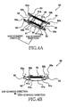
- the two coil springs 54 are tensile springs interconnecting the pair of pivot members 52 that are opposed to each other in the main scanning direction.
- Each of the two coil springs 54 is connected at its opposite end portions to spring supporting portions 52b that are provided in intermediate portions of the side walls of the respective pivot members 53, such that the pivot members 53 are biased or forced to be pivoted toward each other, by a contractive force generated by each of the two coil springs 54, as shown in Fig. 4B .
- the pivot members 52 are pivoted in respective directions that are different from each other, while maintaining a symmetrical positional relationship between the pivot members 52, namely, while theirs positions are held to be symmetrical with each other with respect to a vertical plane that interconnects centers of the respective two coil springs 54.
- a fulcrum-load line and a surface-parallel line cooperate to define therebetween an angle that is not larger than 45°, wherein the spring supporting portion 52b serves as an effort point, wherein the fulcrum-load line passes through a fulcrum point (corresponding to a center of the shaft 51c) and a load point (at which the cam portion 53a is in contact with the contact surface 71b), wherein the surface-parallel line passes through the load point and a point which lies on a parallel plane and which is the closest to the fulcrum point, and wherein the parallel plane contains the load point and is parallel with the nozzle opening surface 2a.
- the elastic force generated by the coil spring 54 is increased with elongation of the coil spring 54.
- the length of the coil spring 54 is increased whereby the elastic force generated by the coil spring 54 is increased.
- the pair of pivot members 52 are biased or forced by the two coil springs 54, whereby the cam portions 53a of the respective pivot members 52 can be moved upwardly and toward inside of the transmission mechanism 50, describing circular arcs.
- the cam portions 53a When the cam portions 53a are moved upwardly and toward the inside of the transmission mechanism, the cam portions 53a upwardly presses the holder 71 while being slid on the contact surface 71b of the holder 71 toward the inside of the transmission mechanism 50, i.e., toward a center of the transmission mechanism 50 in the main scanning direction. Since the holder 71 is forced or pressed upwardly pressed by the cam portions 53a of the respective pivot members 52, the holder 71 is moved upwardly whereby the distance between the cap member 72 and the fixture plate 77 is increased.
- the pair of pivot members 52 are biased or forced, by the two coil springs 54, so as to be pivoted in respective directions that increase the distance between the cap member 72 and the fixture plate 77.
- the bottom surface of the fixture plate 77 which serves as the pressing-force receiving portion, receives a pressing force as a reaction of the pressing force applied from the nozzle opening surface 2a to the cap member 72.
- the distance between the contact surface 71b and the fixture plate 77 is reduced from a distance value d to a distance value d' (that is smaller than the value d), and the pivot members 52 are pivoted in respective directions away from each other, such that the inclination of the above-described fulcrum-load line with respect to the nozzle opening surfaces 2a is reduced, and such that the inclination of a fulcrum-effort line (passing through the fulcrum point and the effort point) with respect to the nozzle opening surface 2a is also reduced.
- the cam portions 53a of the respective pivot members 52 are slidingly moved relative to the contact surface 71b, such that the point (i.e., load point), at which the cam portion 53a of each pivot member 52 is in contact with the contact surface 71b, is moved in a horizontal direction that is away from the corresponding shaft 51c (i.e., fulcrum point), whereby the angle defined between the above-described fulcrum-load line and the above-described surface-parallel line is reduced from an angle ⁇ to an angle ⁇ ' (see Fig. 5 ). As a result of the reduction of this angle, a direction of the pivot motion of each pivot member 52 becomes closer to a vertical direction.
- the point i.e., load point
- a force F0 represents a component of the elastic force F2, which is parallel to the direction of the pivot motion of each pivot member 52, in a stage shown in this view (a) of Fig. 5 .
- a force F0' represents the component of the elastic force F2', which is parallel to the direction of the pivot motion of each pivot member 52, in a stage shown in this view (b) of Fig. 5 .
- a force F1 represents a vertical component of the force F0 (see view (a) of Fig. 5 )
- a force F1' represents a vertical component of the force F0' (see view (b) of Fig. 5 ).
- the vertical component forces F1, F1' each corresponding to a pressing force by which the holder 71 is pressed upwardly by the transmission mechanism 50, can be substantially the same in amount, as shown in Fig. 5 , in spite of change of the elastic force generated by the coil spring 54.
- the reduction of the angle ⁇ leads to the increase of the elastic force F2 generated by the coil spring 54 and also to a reduction of sin ⁇ cos ⁇ . That is, as the angle ⁇ is reduced, a ratio of the vertical component force F1 to the elastic force F2 is reduced.
- the cam portion 53a has the cam profile that is tuned such that the holder 71 is pressed by the substantially constant pressing force F1 while contact of the cam portion 53a with the contact surface 71b is being maintained during the pivot motion of the pivot member 52.
- Fig. 6 is a graph where its abscissa represents a distance of upward movement of the fixture plate 77 while its ordinate represents the pressing force by which the holder 71 is pressed upwardly by the transmission mechanism 50.
- the movement distance of the fixture plate 77 is measured from a position (indicated by zero in the abscissa of the graph) in which the cap member 72 is brought into contact with the nozzle opening surface 2a.
- the graph of Fig. 6 indicates also a relationship between the movement distance of the fixture plate 77 and the pressing force in a conventional capping device.
- a coil spring is provided in place of the transmission mechanism 50 as in the above-identified Patent Literature 1. As shown in the graph of Fig.
- the movement distance and the pressing force are in a proportional relationship in a stage in which the movement distance is larger than zero and smaller than a predetermined range.
- the frame-like protrusion 72b is elastically deformed by an amount that is increased with increase of the movement distance, so that the pressing force - is increased with increase of the movement distance.
- the pressing force is kept substantially in an appropriate amount F1 . That is, the transmission mechanism 50 including the cam portion 53a is constructed such that, in this stage, the nozzle opening surface 2a can be capped by the cap member 72 by substantially the appropriate amount F1 of the pressing force as a constant amount of the pressing force, even with increase of the movement distance.
- the transmission mechanism 50 is configured to transmit, to the holder 71, the pressing force that is applied to the pressing-force receiving portion as a result of pressing of the nozzle opening surface 2a onto the cap member 72, and to restrain increase and reduction of the pressing force such that the transmitted pressing force is held substantially in the appropriate amount F1. It is noted that, in a stage in which the movement distance is larger than the predetermined range, namely, in a stage in which the transmission mechanism 50 is not movable (i.e., in which the pivot members 52 of the transmission mechanism 50 are not pivotable), the movement distance and the pressing force are again in a proportional relationship.
- the frame-like protrusion 72b is further elastically deformed, and the pressing force acting on the nozzle opening surface 2a is excessively increased.
- the vertical movement distance and the pressing force are in a proportional relationship, irrespective of whether the movement distance is large or small. Therefore, in the conventional capping device, the movement distance has to be accurately controlled to establish an appropriate amount F1 of the pressing force. That is, in the conventional capping device, where the cap member is supported by a cap-member support member such as a cap holder, the cap-member support member has to be accurately positioned in a capping position.
- the capping operation which is carried out when the inkjet printer 1 is not operated or when the printer 1 waits to be operated for executing a printing operation.
- the capping operation is carried out for capping or covering the nozzle opening surfaces 2a with the cap members 72 so as to prevent increase of viscosity of the ink within the nozzles.
- the capping device 60 is positioned in a non-capping position (i.e., non-operating position) that is located on a rear side of the inkjet heads 2 (as seen in Fig. 1 ).
- the four inkjet heads 2 are moved upwardly by the frame movement mechanism (not shown).
- the capping device 60 is moved, by the tray movement mechanism (not shown), to a capping position in which the four capping units 62 are opposed to the respective four inkjet heads 4. Then, the four inkjet heads 2 are moved downwardly by the frame movement mechanism.
- Fig. 7 is a set of views showing respective stages of the capping operation.
- view (a) of Fig. 7 when the four inkjet heads 2 are moved downwardly, the positioning pins 2b of the inkjet heads 2 are introduced into the respective positioning holes 75a, 75b of the holder 71, whereby the cap members 72 can be accurately positioned in respective positions that enable the nozzle opening surfaces 2a to be capped or covered by the cap members 72.
- view (b) of Fig. 7 when the four inkjet heads 2 are further moved downwardly, the distal end of the respective fxame-like protrusions 72b are brought into contact with the nozzle opening surfaces 2a.
- the distal end portions of the respective frame-like protrusions 72b are elastically deformed in a contact direction (i.e., in the vertical direction in which the cap members 72 are movable relative to the nozzle opening surfaces 2a) so as to be brought into close contact with the nozzle opening surfaces 2a, whereby the nozzle opening surfaces 2a are capped or covered by the respective cap members 72.
- each cap member 72 is pressed onto the corresponding nozzle opening surface 2a, and the bottom surface of the fixture plate 77, which serves as the pressing-force receiving portion, receives the pressing force as a reaction of the pressing force applied from the nozzle opening surface 2a to the cap member 72.
- the holder 71 is moved downwardly whereby the distance between the contact surface 71b of the holder 71 and the fixture plate 77 is reduced.
- the pair of pivot members 52 of the transmission mechanism 50 are pivoted in respective directions away from each other, whereby the lengths of the respective coil springs 54 are increased.
- each of the coil springs 54 is increased with increase of the length of the coil length 54.
- the pair of pivot members 52 are pivoted in respective directions away from each other such that the inclination of the above-described fulcrum-load line with respect to the nozzle opening surfaces 2a is reduced (wherein the spring supporting portion 52b serves as the effort point, the shaft 51c serves as the fulcrum point, and the point at which the cam portion 53a is in contact with the contact surface 71b serves as the load point).
- the cam portions 53a are slidingly moved relative to the contact surface 71b, such that the holder 71 is pressed upwardly by the pivot members 52 by the pressing force F1 that is substantially constant.
- the transmission mechanism 50 is configured to restrain increase and reduction of the pressing force that is applied to the cap member 72, so that it is possible to cause the cap member 72 to be held in stable contact with the nozzle opening surface 2a by the pressing force F1 that is held in a given amount range. Owing to this arrangement, it is possible to restrain the cap member 72 from being in contact with the nozzle opening surface 2a by an excessively increased pressing force and to accordingly prevent the cap member 72 and the nozzle opening surface 2a from being deformed to abnormal states. Further, it is possible to avoid insufficiency of the pressing force and to reliably establish a sufficient degree of tightness between the cap member 72 and the nozzle opening surface 2a.
- the transmission mechanism 50 has the pair of pivot members 52 which are opposed to each other (in the main scanning direction) and which are connected to each other via the coil springs 54.
- Each of the coil springs 54 is arranged to force the pivot members 52 in respective directions that cause the load points (provided by the cam portions 53a of the respective pivot members 52) to be displaced toward each other.
- the fulcrum-load line and the surface-parallel line cooperate to define therebetween the angle that is not larger than 45°, wherein the spring supporting portion 52b serves as the effort point, wherein the fulcrum-load line passes through the fulcrum point (corresponding to the shaft 51c) and the load point (at which the cam portion 53a is in contact with the contact surface 71b), wherein the surface-parallel line passes through the load point and the point which lies on the parallel plane and which is the closest to the fulcrum point, and wherein the parallel plane contains the load point and is parallel with the nozzle opening surface 2a.
- the pivot members 52 can be pivoted reliably in respective directions that cause the cap-structure-direction force component (transmitted through the pivot members 52 and acting in the direction toward the cap structure) to be reduced.
- the transmission mechanism 50 can be activated within a range in which the mechanism is geometrically balanced.
- the cam portions 53a having given curved surfaces are provided in distal end portions of the respective contact members 53, and the pivot members 52 are in contact at the cam portions 53a with the holder 71. Owing to this arrangement which requires merely an inexpensive construction with provision of the cam portions 53a, when the pivot members 52 are being pivoted, the fluctuation of the pressing force can be reduced by the contact of the cam portions 53a with the contact surface 71b of the holder 71, which contact enables the pivot members 52 to be smoothly pivoted.
- each of the capping units 62 has the total of four transmission mechanisms 50 that are arranged in the main scanning direction in which each of the nozzle opening surfaces 2a is elongated. Owing to this arrangement, the pressing force can be efficiently applied to entirety of the holder 71 via an increased number of load points which are distant from one another in the main scanning direction.
- the cap member 72 is an elastically deformable member, it is possible to establish a high degree of followability of the cap member 72 with respect to configuration of the nozzle opening surface 2a. That is, even if the elongated nozzle opening surface 2a has a poor flatness due to its warp, for example, the distal end portion of the frame-like protrusion 72b can be brought into close contact with the elongated nozzle opening surface 2a, owing to suitable deformation of the bottom plate 72a of the cap member 72. Further, since the pressing force whose amount is substantially constant can be applied evenly to the elongated nozzle opening surface 2a, the elongated nozzle opening surface 2a can be stably covered by the cap member 72.
- the pressing force F1 can be applied evenly to the entirety of the cap member 72 even if the elongated nozzle opening surface 2a has a poor flatness as long as the flatness is not larger than a size of the above-described predetermined range shown in the graph of Fig. 6 , and the nozzle opening surface 2a can be reliably covered with the cap member 72 with the pressing force F1 which is kept constant while the upward movement distance of the fixture plate 77 is within the above-described predetermined range shown in Fig. 6 .
- the cap structure is constituted by the cap member 72 and the holder 72 as the reinforcement member which supports the cap member 72, so that it is possible to prevent the cap member 72 from being excessively deformed.
- the cam portions 53a of the pivot members 52 are positioned in respective positions that are opposed to the frame-like protrusion 72b of the cap member 72, so that the pressing force can be efficiently applied to the frame-like protrusion portion 72b, whereby the frame-like protrusion portion 72b can be reliably brought into contact with the nozzle opening surface 2a.
- the distal end portion of the frame-like protrusion 72b is elastically deformable in above-described the contact direction, so that the frame-like protrusion portion 72b can be reliably brought into close contact with the nozzle opening surfaces 2a.
- the fixture plate 77 is made of a resin material so that the capping unit 62 as a whole can be made light in weight.
- each transmission mechanism 50 is fixed to the fixture plate 77 in the above-described embodiment, each transmission mechanism 50 may be fixed to the holder 71 as shown in Fig. 8A . In this modified arrangement, the cam portions 53a of each transmission mechanism 50 are held in slidable contact with the fixture plate 77. It is noted that each transmission mechanism 50 does not necessarily have to be fixed to the fixture plate 77 but may be simply disposed on the fixture plate 77.
- each transmission mechanism 50 is constituted by the pair of pivot members 52 and the coil springs 54 interconnecting the pair of pivot members 52.
- the construction of each transmission mechanism 50 may be modified as needed.
- the pivot members 52 may be biased or forced by respective springs that are different from each other.
- each transmission mechanism may be constituted by a single pivot member 52 and the coil spring or springs 54 that bias or force the single pivot member 52, as shown in Fig. 8B .
- each transmission mechanism may include a spring unit that is a combination of a plurality of springs having respective spring constants that are different from each other, such that the pressing force applied to the holder 71 is not changed depending on the distance between the holder 71 and the fixture plate 77.
- the above-described fulcrum-load line and the above-described surface-parallel line cooperate to define therebetween the angle that is not larger than 45°. However, this angle may be larger than 45°.
- the cam portion 53a which is provided in the distal end portion of each contact member 53, has a given cam profile.
- the cam portion 53a may have any desired shape such as a simple curved shape.
- the cam portion 53a may be provided by a roller member or a ball member that is rotatably held in each contact member 53 so that it is possible to reduce a resistance acting against the slide movement of the cam portion 53a on the constant surface 71b of the holder 71.
- each capping unit 62 includes the four transmission mechanisms 50 arranged in the main scanning direction in which the nozzle opening surface 2a is elongated.
- the number of the transmission mechanism or mechanisms 50 included in each capping unit 62 may be one, two, three or more than four. Further, the plurality of transmission mechanisms 50 may be arranged in any desired pattern.
- the entirety of the cap member 72 is made of an elastic material. However, only a part of the cap member 72 may be made of the elastic material.
- the present invention is applied to the inkjet printer 1.
- the present invention is applicable also to an apparatus having a liquid ejection head that is configured to eject a liquid other than the ink.
- the present invention is applied to the capping device that is configured to cap or cover each nozzle opening surface 2a.
- the present invention is applicable to a capping device that is configured to cap or cover a surface of an object, which is other than the nozzle opening surface 2a.
Landscapes
- Ink Jet (AREA)
- Closing Of Containers (AREA)
Claims (13)
- Dispositif d'obturation (60) comprenant :une structure d'obturateur (71 ; 72) pour recouvrir une surface d'un objet en la déplaçant par rapport à l'objet (2), dans une direction de contact vers une surface (2a) de l'objet (2) à amener en contact avec la surface (2a) ;un mécanisme de transmission (50) configuré pour transmettre, à ladite structure d'obturateur (71 ; 72), une force de pression (F1) qui amène ladite structure d'obturateur (71 ; 72) à être amenée en contact avec la surface (2a) ; etun élément de support (77) qui supporte ledit mécanisme de transmission (50) ;ledit mécanisme de transmission (50) étant configuré pour limiter l'augmentation et la réduction de la force de pression (F1), de sorte que la force de pression (F1) transmise à ladite structure d'obturateur (71 ; 72) est maintenue dans une plage de valeurs donnée au moins lorsqu'une distance entre ladite structure d'obturateur (71 ; 72) et ledit élément de support (77) dans la direction de contact est dans une plage de distances donnée alors que ladite structure d'obturateur (71 ; 72) est en contact avec la surface (2a), et dans lequelledit mécanisme de transmission (50) comprend un élément de pivot (52) maintenu par un arbre (51c) qui est fixe par rapport à celui de ladite structure d'obturateur (71 ; 72) et dudit élément de support (77) et peut pivoter autour d'un axe dudit arbre (51c) qui est parallèle à la surface (2a) de l'objet (2), ledit mécanisme de transmission (50) étant configuré pour modifier la distance entre ladite structure d'obturateur (71 ; 72) et ledit élément de support (77) lorsque ledit élément de pivot (52) est pivoté autour de l'axe alors que ledit élément de pivot (52) est en contact avec l'autre parmi ladite structure d'obturateur (71 ; 72) et ledit élément de support (77), caractérisé en ce que ledit mécanisme de transmission (50) comprend en outre :un élément élastique (54) qui force ledit élément de pivot (52) à pivoter dans une direction qui augmente la distance entre ladite structure d'obturateur (71 ; 72) et ledit élément de support (77),et dans lequel ledit élément élastique (54) force ledit élément de pivot (52) par une force élastique (F2) qui est augmentée au fur et à mesure qu'une inclinaison d'une ligne de tension d'appui par rapport à la surface (2a) de l'objet (2) est réduite par le mouvement de pivot dudit élément de pivot (52), la ligne de tension d'appui passant par un point d'appui et un point de tension (52b), le point d'appui étant une intersection de l'axe et dudit élément de pivot (52), le point de tension (52b) étant un point auquel la force élastique (F2) est appliquée sur ledit élément de pivot (52) à partir dudit élément élastique (54).
- Dispositif d'obturation (60) selon la revendication 1, dans lequel ledit élément de support (77) comprend une partie de réception de force de pression (F1) au niveau de laquelle la force de pression (F1) doit être reçue par ledit élément de support (77).
- Dispositif d'obturation (60) selon la revendication 1,
dans lequel ledit mécanisme de transmission (50) comprend deux éléments de pivot (52), chacun fourni par ledit élément de pivot (52),
et dans lequel ledit élément élastique (54) force chacun desdits deux éléments de pivot (52) à pivoter dans une direction qui amène le point de tension (52b) auquel la force élastique (F2) est appliquée sur chacun desdits deux éléments de pivot (52), à être déplacé vers le point de tension (52b) auquel la force élastique (F2) est appliquée sur l'autre desdits deux éléments de pivot (52). - Dispositif d'obturation (60) selon la revendication 1 ou 3, dans lequel une ligne de charge d'appui et une ligne parallèle à la surface coopèrent afin de définir entre elles un angle (θ) qui n'est pas supérieur à 45°, alors que ladite structure d'obturateur (71 ; 72) est en contact avec la surface (2a) de l'objet (2), la ligne de charge d'appui passant par le point d'appui et un point de contact au niveau auquel ledit élément de pivot (52) est en contact avec l'autre parmi ladite structure d'obturateur (71 ; 72) et ledit élément de support (77), la ligne parallèle à la surface passant par le point de contact et le point d'appui le plus proche qui se trouve sur un plan contenant le point de contact et parallèle à la surface (2a) et qui est le plus proche du point d'appui.
- Dispositif d'obturation (60) selon l'une quelconque des revendications 1, 3 et 4, dans lequel ledit élément de pivot (52) comprend une partie de came (53a) ayant un profil de came donné, et est en contact au niveau de sa partie de came (53a) avec ledit autre parmi ladite structure d'obturateur (71 ; 72) et ledit élément de support (77).
- Dispositif d'obturation (60) selon l'une quelconque des revendications 1 à 5, comprenant une pluralité de mécanismes de transmission (50), chacun fourni par ledit mécanisme de transmission (50),
dans lequel ladite structure d'obturateur (71 ; 72) est allongée dans une direction donnée, pour recouvrir ainsi la surface (2a) qui est allongée dans la direction donnée,
et dans lequel ladite pluralité de mécanismes de transmission (50) sont agencés dans la direction donnée. - Dispositif d'obturation (60) selon la revendication 6,
dans lequel ladite structure d'obturateur (71 ; 72) comprend un élément d'obturateur (72) qui doit être amené en contact avec la surface (2a) de l'objet (2),
et dans lequel ledit élément d'obturateur (72) est un élément élastiquement déformable. - Dispositif d'obturation (60) selon la revendication 7,
dans lequel ladite structure d'obturateur (71 ; 72) comprend, en plus dudit élément d'obturateur (72), un élément de renforcement (71) qui est fixé sur ledit élément d'obturateur (72) pour renforcer ainsi ledit élément d'obturateur (72),
et dans lequel chacun de ladite pluralité de mécanismes de transmission (50) est en contact avec ledit élément de renforcement, pour transmettre ainsi la force de pression (F1) audit élément d'obturateur (72). - Dispositif d'obturation (60) selon l'une quelconque des revendications 1 à 8,
dans lequel ladite structure d'obturateur (71 ; 72) a une partie de plaque inférieure (72a) et une partie de saillie en forme de bâti (72b) qui fait saillie de ladite partie de plaque inférieure (72a) et qui doit être amenée en contact avec la surface (2a) de l'objet (2),
et dans lequel ledit élément de pivot (52) comprend une partie de contact (53) qui est en contact avec ladite structure d'obturateur (71 ; 72) alors que ladite partie de contact est positionnée dans une position qui est opposée à ladite partie de saillie en forme de bâti (72b) de ladite structure d'obturateur (71 ; 72) dans ladite direction de contact. - Dispositif d'obturation (60) selon l'une quelconque des revendications 1 à 9,
dans lequel ladite structure d'obturateur (71 ; 72) a une partie de plaque inférieure (72a) et une partie de saillie en forme de bâti (72b) qui fait saillie de ladite partie de plaque inférieure (72a) et qui doit être amenée en contact avec la surface (2a) de l'objet (2),
et dans lequel ladite partie de saillie en forme de bâti (72b) de ladite structure d'obturateur (71 ; 72) est élastiquement déformable dans ladite direction de contact. - Dispositif d'obturation (60) selon l'une quelconque des revendications 1 à 10, dans lequel ledit élément de support (77) est un élément (77) réalisé à partir d'une résine.
- Dispositif d'obturation (60) selon l'une quelconque des revendications 1 à 11, dans lequel ladite structure d'obturateur (71 ; 72) doit être amenée en contact avec, en tant que surface (2a) de l'objet (2), une surface d'ouverture de sortie d'éjection (2a) d'une tête d'éjection de liquide (2) dans laquelle les sorties d'éjection s'ouvrent de sorte que le liquide doit être éjecté de la tête d'éjection de liquide (2) par les sorties d'éjection.
- Appareil d'éjection de liquide (1) comprenant :une tête d'éjection de liquide (2) comprenant une surface d'ouverture de sortie d'éjection (2a) dans laquelle les sorties d'éjection s'ouvrent de sorte que le liquide doit être éjecté de ladite tête d'éjection de liquide (2) par lesdites sorties d'éjection ;le dispositif d'obturation (60) selon l'une quelconque des revendications 1 à 12, de sorte que ladite structure d'obturateur (71 ; 72) doit être amenée en contact avec ladite surface d'ouverture de sortie d'éjection (2a) en tant que surface (2a) de l'objet (2) ; etchacun parmi au moins l'un de ladite tête d'éjection de liquide (2) et ledit élément de support (77) est mobile par rapport à l'autre parmi ladite tête d'éjection de liquide (2) et ledit élément de support (77) dans la direction de contact.
Applications Claiming Priority (1)
| Application Number | Priority Date | Filing Date | Title |
|---|---|---|---|
| JP2009270527A JP5316384B2 (ja) | 2009-11-27 | 2009-11-27 | キャッピング装置及び記録液体吐出装置 |
Publications (3)
| Publication Number | Publication Date |
|---|---|
| EP2327552A2 EP2327552A2 (fr) | 2011-06-01 |
| EP2327552A3 EP2327552A3 (fr) | 2012-05-02 |
| EP2327552B1 true EP2327552B1 (fr) | 2013-06-26 |
Family
ID=43825335
Family Applications (1)
| Application Number | Title | Priority Date | Filing Date |
|---|---|---|---|
| EP10010215.1A Not-in-force EP2327552B1 (fr) | 2009-11-27 | 2010-09-22 | Dispositif de capsulage et appareil d'éjection de liquide |
Country Status (4)
| Country | Link |
|---|---|
| US (1) | US8708455B2 (fr) |
| EP (1) | EP2327552B1 (fr) |
| JP (1) | JP5316384B2 (fr) |
| CN (1) | CN102079169B (fr) |
Families Citing this family (3)
| Publication number | Priority date | Publication date | Assignee | Title |
|---|---|---|---|---|
| EP2755825B1 (fr) * | 2011-09-13 | 2015-11-18 | Videojet Technologies Inc. | Dispositif d'obturation par capuchon |
| JP7005908B2 (ja) * | 2017-02-27 | 2022-01-24 | セイコーエプソン株式会社 | 液体噴射ヘッドユニット及び液体噴射装置 |
| JP7001115B2 (ja) * | 2020-02-27 | 2022-01-19 | セイコーエプソン株式会社 | 液体噴射ヘッド、ヘッドユニット、および、液体噴射装置 |
Family Cites Families (8)
| Publication number | Priority date | Publication date | Assignee | Title |
|---|---|---|---|---|
| JP3039213B2 (ja) | 1993-08-18 | 2000-05-08 | 富士通株式会社 | Ipl装置指定方法 |
| JPH08224880A (ja) | 1995-02-21 | 1996-09-03 | Canon Inc | インクジェット記録装置 |
| JPH11314628A (ja) * | 1998-05-07 | 1999-11-16 | Sekisui Plastics Co Ltd | 容 器 |
| JP2004284208A (ja) * | 2003-03-24 | 2004-10-14 | Mutoh Ind Ltd | インクジェットプリンタ |
| JP3960246B2 (ja) * | 2003-03-28 | 2007-08-15 | ブラザー工業株式会社 | インクジェットプリンタ |
| KR100667847B1 (ko) | 2005-12-23 | 2007-01-11 | 삼성전자주식회사 | 잉크젯 화상형성장치 |
| JP2008200849A (ja) * | 2007-02-16 | 2008-09-04 | Brother Ind Ltd | インクジェット記録装置 |
| JP5162984B2 (ja) * | 2007-07-13 | 2013-03-13 | セイコーエプソン株式会社 | 流体噴射装置 |
-
2009
- 2009-11-27 JP JP2009270527A patent/JP5316384B2/ja not_active Expired - Fee Related
-
2010
- 2010-09-22 EP EP10010215.1A patent/EP2327552B1/fr not_active Not-in-force
- 2010-09-28 US US12/892,901 patent/US8708455B2/en active Active
- 2010-10-20 CN CN2010105163844A patent/CN102079169B/zh not_active Expired - Fee Related
Also Published As
| Publication number | Publication date |
|---|---|
| US20110128322A1 (en) | 2011-06-02 |
| JP2011110861A (ja) | 2011-06-09 |
| JP5316384B2 (ja) | 2013-10-16 |
| CN102079169A (zh) | 2011-06-01 |
| CN102079169B (zh) | 2013-10-02 |
| US8708455B2 (en) | 2014-04-29 |
| EP2327552A2 (fr) | 2011-06-01 |
| EP2327552A3 (fr) | 2012-05-02 |
Similar Documents
| Publication | Publication Date | Title |
|---|---|---|
| US8042907B2 (en) | Liquid ejection device | |
| JP4998243B2 (ja) | 液体吐出装置 | |
| US8449071B2 (en) | Image forming apparatus | |
| US7427122B2 (en) | Printer maintenance apparatus | |
| EP2327552B1 (fr) | Dispositif de capsulage et appareil d'éjection de liquide | |
| US8287068B2 (en) | Liquid discharge apparatus with platen and platen moving device and method for controlling the same | |
| EP2383120B1 (fr) | Appareil d'enregistrement à jet d'encre | |
| KR20190005909A (ko) | 잉크젯 인쇄 장치 | |
| US8465122B2 (en) | Liquid jetting apparatus | |
| US11338584B2 (en) | Liquid ejection apparatus | |
| US8052247B2 (en) | Image forming apparatus | |
| JP4013909B2 (ja) | 液体噴射装置 | |
| CN100450776C (zh) | 成像设备 | |
| JP2011136487A (ja) | 液体吐出装置 | |
| US8596751B2 (en) | Head cap and ink-jet printer | |
| JP5012765B2 (ja) | ヘッドキャップ | |
| US12023932B2 (en) | Image forming apparatus | |
| JP7155913B2 (ja) | メンテナンスユニットおよびそれを備えたインクジェット記録装置 | |
| JP4978613B2 (ja) | ヘッドキャップ | |
| US20260109150A1 (en) | Liquid ejection apparatus | |
| US9849679B2 (en) | Liquid jetting apparatus, power transmission apparatus, and recording apparatus | |
| JP7225639B2 (ja) | 画像記録装置 | |
| JP2010115881A (ja) | ヘッドキャップ | |
| JP2010082997A (ja) | ヘッドキャップ |
Legal Events
| Date | Code | Title | Description |
|---|---|---|---|
| PUAI | Public reference made under article 153(3) epc to a published international application that has entered the european phase |
Free format text: ORIGINAL CODE: 0009012 |
|
| AK | Designated contracting states |
Kind code of ref document: A2 Designated state(s): AL AT BE BG CH CY CZ DE DK EE ES FI FR GB GR HR HU IE IS IT LI LT LU LV MC MK MT NL NO PL PT RO SE SI SK SM TR |
|
| AX | Request for extension of the european patent |
Extension state: BA ME RS |
|
| PUAL | Search report despatched |
Free format text: ORIGINAL CODE: 0009013 |
|
| AK | Designated contracting states |
Kind code of ref document: A3 Designated state(s): AL AT BE BG CH CY CZ DE DK EE ES FI FR GB GR HR HU IE IS IT LI LT LU LV MC MK MT NL NO PL PT RO SE SI SK SM TR |
|
| AX | Request for extension of the european patent |
Extension state: BA ME RS |
|
| RIC1 | Information provided on ipc code assigned before grant |
Ipc: B41J 2/165 20060101AFI20120329BHEP |
|
| 17P | Request for examination filed |
Effective date: 20121102 |
|
| GRAP | Despatch of communication of intention to grant a patent |
Free format text: ORIGINAL CODE: EPIDOSNIGR1 |
|
| GRAS | Grant fee paid |
Free format text: ORIGINAL CODE: EPIDOSNIGR3 |
|
| GRAA | (expected) grant |
Free format text: ORIGINAL CODE: 0009210 |
|
| AK | Designated contracting states |
Kind code of ref document: B1 Designated state(s): AL AT BE BG CH CY CZ DE DK EE ES FI FR GB GR HR HU IE IS IT LI LT LU LV MC MK MT NL NO PL PT RO SE SI SK SM TR |
|
| REG | Reference to a national code |
Ref country code: GB Ref legal event code: FG4D |
|
| REG | Reference to a national code |
Ref country code: CH Ref legal event code: EP |
|
| REG | Reference to a national code |
Ref country code: AT Ref legal event code: REF Ref document number: 618518 Country of ref document: AT Kind code of ref document: T Effective date: 20130715 |
|
| REG | Reference to a national code |
Ref country code: IE Ref legal event code: FG4D |
|
| REG | Reference to a national code |
Ref country code: DE Ref legal event code: R096 Ref document number: 602010007999 Country of ref document: DE Effective date: 20130822 |
|
| PG25 | Lapsed in a contracting state [announced via postgrant information from national office to epo] |
Ref country code: SE Free format text: LAPSE BECAUSE OF FAILURE TO SUBMIT A TRANSLATION OF THE DESCRIPTION OR TO PAY THE FEE WITHIN THE PRESCRIBED TIME-LIMIT Effective date: 20130626 Ref country code: FI Free format text: LAPSE BECAUSE OF FAILURE TO SUBMIT A TRANSLATION OF THE DESCRIPTION OR TO PAY THE FEE WITHIN THE PRESCRIBED TIME-LIMIT Effective date: 20130626 Ref country code: GR Free format text: LAPSE BECAUSE OF FAILURE TO SUBMIT A TRANSLATION OF THE DESCRIPTION OR TO PAY THE FEE WITHIN THE PRESCRIBED TIME-LIMIT Effective date: 20130927 Ref country code: NO Free format text: LAPSE BECAUSE OF FAILURE TO SUBMIT A TRANSLATION OF THE DESCRIPTION OR TO PAY THE FEE WITHIN THE PRESCRIBED TIME-LIMIT Effective date: 20130926 Ref country code: LT Free format text: LAPSE BECAUSE OF FAILURE TO SUBMIT A TRANSLATION OF THE DESCRIPTION OR TO PAY THE FEE WITHIN THE PRESCRIBED TIME-LIMIT Effective date: 20130626 Ref country code: SI Free format text: LAPSE BECAUSE OF FAILURE TO SUBMIT A TRANSLATION OF THE DESCRIPTION OR TO PAY THE FEE WITHIN THE PRESCRIBED TIME-LIMIT Effective date: 20130626 |
|
| REG | Reference to a national code |
Ref country code: AT Ref legal event code: MK05 Ref document number: 618518 Country of ref document: AT Kind code of ref document: T Effective date: 20130626 |
|
| REG | Reference to a national code |
Ref country code: LT Ref legal event code: MG4D |
|
| PG25 | Lapsed in a contracting state [announced via postgrant information from national office to epo] |
Ref country code: HR Free format text: LAPSE BECAUSE OF FAILURE TO SUBMIT A TRANSLATION OF THE DESCRIPTION OR TO PAY THE FEE WITHIN THE PRESCRIBED TIME-LIMIT Effective date: 20130626 Ref country code: BG Free format text: LAPSE BECAUSE OF FAILURE TO SUBMIT A TRANSLATION OF THE DESCRIPTION OR TO PAY THE FEE WITHIN THE PRESCRIBED TIME-LIMIT Effective date: 20130926 |
|
| REG | Reference to a national code |
Ref country code: NL Ref legal event code: VDEP Effective date: 20130626 |
|
| PG25 | Lapsed in a contracting state [announced via postgrant information from national office to epo] |
Ref country code: LV Free format text: LAPSE BECAUSE OF FAILURE TO SUBMIT A TRANSLATION OF THE DESCRIPTION OR TO PAY THE FEE WITHIN THE PRESCRIBED TIME-LIMIT Effective date: 20130626 |
|
| PG25 | Lapsed in a contracting state [announced via postgrant information from national office to epo] |
Ref country code: SK Free format text: LAPSE BECAUSE OF FAILURE TO SUBMIT A TRANSLATION OF THE DESCRIPTION OR TO PAY THE FEE WITHIN THE PRESCRIBED TIME-LIMIT Effective date: 20130626 Ref country code: CZ Free format text: LAPSE BECAUSE OF FAILURE TO SUBMIT A TRANSLATION OF THE DESCRIPTION OR TO PAY THE FEE WITHIN THE PRESCRIBED TIME-LIMIT Effective date: 20130626 Ref country code: IS Free format text: LAPSE BECAUSE OF FAILURE TO SUBMIT A TRANSLATION OF THE DESCRIPTION OR TO PAY THE FEE WITHIN THE PRESCRIBED TIME-LIMIT Effective date: 20131026 Ref country code: BE Free format text: LAPSE BECAUSE OF FAILURE TO SUBMIT A TRANSLATION OF THE DESCRIPTION OR TO PAY THE FEE WITHIN THE PRESCRIBED TIME-LIMIT Effective date: 20130626 Ref country code: PT Free format text: LAPSE BECAUSE OF FAILURE TO SUBMIT A TRANSLATION OF THE DESCRIPTION OR TO PAY THE FEE WITHIN THE PRESCRIBED TIME-LIMIT Effective date: 20131028 Ref country code: CY Free format text: LAPSE BECAUSE OF FAILURE TO SUBMIT A TRANSLATION OF THE DESCRIPTION OR TO PAY THE FEE WITHIN THE PRESCRIBED TIME-LIMIT Effective date: 20130717 Ref country code: EE Free format text: LAPSE BECAUSE OF FAILURE TO SUBMIT A TRANSLATION OF THE DESCRIPTION OR TO PAY THE FEE WITHIN THE PRESCRIBED TIME-LIMIT Effective date: 20130626 Ref country code: AT Free format text: LAPSE BECAUSE OF FAILURE TO SUBMIT A TRANSLATION OF THE DESCRIPTION OR TO PAY THE FEE WITHIN THE PRESCRIBED TIME-LIMIT Effective date: 20130626 |
|
| PG25 | Lapsed in a contracting state [announced via postgrant information from national office to epo] |
Ref country code: RO Free format text: LAPSE BECAUSE OF FAILURE TO SUBMIT A TRANSLATION OF THE DESCRIPTION OR TO PAY THE FEE WITHIN THE PRESCRIBED TIME-LIMIT Effective date: 20130626 Ref country code: ES Free format text: LAPSE BECAUSE OF FAILURE TO SUBMIT A TRANSLATION OF THE DESCRIPTION OR TO PAY THE FEE WITHIN THE PRESCRIBED TIME-LIMIT Effective date: 20131007 Ref country code: NL Free format text: LAPSE BECAUSE OF FAILURE TO SUBMIT A TRANSLATION OF THE DESCRIPTION OR TO PAY THE FEE WITHIN THE PRESCRIBED TIME-LIMIT Effective date: 20130626 Ref country code: PL Free format text: LAPSE BECAUSE OF FAILURE TO SUBMIT A TRANSLATION OF THE DESCRIPTION OR TO PAY THE FEE WITHIN THE PRESCRIBED TIME-LIMIT Effective date: 20130626 |
|
| PG25 | Lapsed in a contracting state [announced via postgrant information from national office to epo] |
Ref country code: CY Free format text: LAPSE BECAUSE OF FAILURE TO SUBMIT A TRANSLATION OF THE DESCRIPTION OR TO PAY THE FEE WITHIN THE PRESCRIBED TIME-LIMIT Effective date: 20130626 |
|
| PG25 | Lapsed in a contracting state [announced via postgrant information from national office to epo] |
Ref country code: MC Free format text: LAPSE BECAUSE OF FAILURE TO SUBMIT A TRANSLATION OF THE DESCRIPTION OR TO PAY THE FEE WITHIN THE PRESCRIBED TIME-LIMIT Effective date: 20130626 Ref country code: DK Free format text: LAPSE BECAUSE OF FAILURE TO SUBMIT A TRANSLATION OF THE DESCRIPTION OR TO PAY THE FEE WITHIN THE PRESCRIBED TIME-LIMIT Effective date: 20130626 |
|
| PLBE | No opposition filed within time limit |
Free format text: ORIGINAL CODE: 0009261 |
|
| STAA | Information on the status of an ep patent application or granted ep patent |
Free format text: STATUS: NO OPPOSITION FILED WITHIN TIME LIMIT |
|
| PG25 | Lapsed in a contracting state [announced via postgrant information from national office to epo] |
Ref country code: IT Free format text: LAPSE BECAUSE OF FAILURE TO SUBMIT A TRANSLATION OF THE DESCRIPTION OR TO PAY THE FEE WITHIN THE PRESCRIBED TIME-LIMIT Effective date: 20130626 |
|
| 26N | No opposition filed |
Effective date: 20140327 |
|
| REG | Reference to a national code |
Ref country code: IE Ref legal event code: MM4A |
|
| REG | Reference to a national code |
Ref country code: DE Ref legal event code: R097 Ref document number: 602010007999 Country of ref document: DE Effective date: 20140327 |
|
| PG25 | Lapsed in a contracting state [announced via postgrant information from national office to epo] |
Ref country code: IE Free format text: LAPSE BECAUSE OF NON-PAYMENT OF DUE FEES Effective date: 20130922 |
|
| REG | Reference to a national code |
Ref country code: CH Ref legal event code: PL |
|
| PG25 | Lapsed in a contracting state [announced via postgrant information from national office to epo] |
Ref country code: SM Free format text: LAPSE BECAUSE OF FAILURE TO SUBMIT A TRANSLATION OF THE DESCRIPTION OR TO PAY THE FEE WITHIN THE PRESCRIBED TIME-LIMIT Effective date: 20130626 |
|
| PG25 | Lapsed in a contracting state [announced via postgrant information from national office to epo] |
Ref country code: MT Free format text: LAPSE BECAUSE OF FAILURE TO SUBMIT A TRANSLATION OF THE DESCRIPTION OR TO PAY THE FEE WITHIN THE PRESCRIBED TIME-LIMIT Effective date: 20130626 Ref country code: TR Free format text: LAPSE BECAUSE OF FAILURE TO SUBMIT A TRANSLATION OF THE DESCRIPTION OR TO PAY THE FEE WITHIN THE PRESCRIBED TIME-LIMIT Effective date: 20130626 |
|
| PG25 | Lapsed in a contracting state [announced via postgrant information from national office to epo] |
Ref country code: HU Free format text: LAPSE BECAUSE OF FAILURE TO SUBMIT A TRANSLATION OF THE DESCRIPTION OR TO PAY THE FEE WITHIN THE PRESCRIBED TIME-LIMIT; INVALID AB INITIO Effective date: 20100922 Ref country code: MK Free format text: LAPSE BECAUSE OF FAILURE TO SUBMIT A TRANSLATION OF THE DESCRIPTION OR TO PAY THE FEE WITHIN THE PRESCRIBED TIME-LIMIT Effective date: 20130626 Ref country code: CH Free format text: LAPSE BECAUSE OF NON-PAYMENT OF DUE FEES Effective date: 20140930 Ref country code: LI Free format text: LAPSE BECAUSE OF NON-PAYMENT OF DUE FEES Effective date: 20140930 Ref country code: LU Free format text: LAPSE BECAUSE OF NON-PAYMENT OF DUE FEES Effective date: 20130922 |
|
| REG | Reference to a national code |
Ref country code: FR Ref legal event code: PLFP Year of fee payment: 7 |
|
| REG | Reference to a national code |
Ref country code: FR Ref legal event code: PLFP Year of fee payment: 8 |
|
| REG | Reference to a national code |
Ref country code: FR Ref legal event code: PLFP Year of fee payment: 9 |
|
| PG25 | Lapsed in a contracting state [announced via postgrant information from national office to epo] |
Ref country code: AL Free format text: LAPSE BECAUSE OF FAILURE TO SUBMIT A TRANSLATION OF THE DESCRIPTION OR TO PAY THE FEE WITHIN THE PRESCRIBED TIME-LIMIT Effective date: 20130626 |
|
| P01 | Opt-out of the competence of the unified patent court (upc) registered |
Effective date: 20230529 |
|
| PGFP | Annual fee paid to national office [announced via postgrant information from national office to epo] |
Ref country code: GB Payment date: 20230810 Year of fee payment: 14 |
|
| PGFP | Annual fee paid to national office [announced via postgrant information from national office to epo] |
Ref country code: FR Payment date: 20230807 Year of fee payment: 14 Ref country code: DE Payment date: 20230808 Year of fee payment: 14 |
|
| REG | Reference to a national code |
Ref country code: DE Ref legal event code: R119 Ref document number: 602010007999 Country of ref document: DE |
|
| GBPC | Gb: european patent ceased through non-payment of renewal fee |
Effective date: 20240922 |
|
| PG25 | Lapsed in a contracting state [announced via postgrant information from national office to epo] |
Ref country code: DE Free format text: LAPSE BECAUSE OF NON-PAYMENT OF DUE FEES Effective date: 20250401 |
|
| PG25 | Lapsed in a contracting state [announced via postgrant information from national office to epo] |
Ref country code: GB Free format text: LAPSE BECAUSE OF NON-PAYMENT OF DUE FEES Effective date: 20240922 |
|
| PG25 | Lapsed in a contracting state [announced via postgrant information from national office to epo] |
Ref country code: FR Free format text: LAPSE BECAUSE OF NON-PAYMENT OF DUE FEES Effective date: 20240930 |