EP2326780B1 - Lock unit having a multi-pawl locking mechanism - Google Patents
Lock unit having a multi-pawl locking mechanism Download PDFInfo
- Publication number
- EP2326780B1 EP2326780B1 EP20090748949 EP09748949A EP2326780B1 EP 2326780 B1 EP2326780 B1 EP 2326780B1 EP 20090748949 EP20090748949 EP 20090748949 EP 09748949 A EP09748949 A EP 09748949A EP 2326780 B1 EP2326780 B1 EP 2326780B1
- Authority
- EP
- European Patent Office
- Prior art keywords
- pawl
- lever
- catch
- lock unit
- blocking lever
- Prior art date
- Legal status (The legal status is an assumption and is not a legal conclusion. Google has not performed a legal analysis and makes no representation as to the accuracy of the status listed.)
- Not-in-force
Links
- 230000000903 blocking effect Effects 0.000 claims description 46
- 230000002093 peripheral effect Effects 0.000 description 3
- 230000003111 delayed effect Effects 0.000 description 2
- 230000001419 dependent effect Effects 0.000 description 1
- 230000000977 initiatory effect Effects 0.000 description 1
- 230000036316 preload Effects 0.000 description 1
Images

Classifications
-
- E—FIXED CONSTRUCTIONS
- E05—LOCKS; KEYS; WINDOW OR DOOR FITTINGS; SAFES
- E05B—LOCKS; ACCESSORIES THEREFOR; HANDCUFFS
- E05B85/00—Details of vehicle locks not provided for in groups E05B77/00 - E05B83/00
- E05B85/20—Bolts or detents
- E05B85/24—Bolts rotating about an axis
- E05B85/26—Cooperation between bolts and detents
-
- E—FIXED CONSTRUCTIONS
- E05—LOCKS; KEYS; WINDOW OR DOOR FITTINGS; SAFES
- E05B—LOCKS; ACCESSORIES THEREFOR; HANDCUFFS
- E05B15/00—Other details of locks; Parts for engagement by bolts of fastening devices
- E05B15/16—Use of special materials for parts of locks
- E05B2015/1685—Sheet materials
-
- Y—GENERAL TAGGING OF NEW TECHNOLOGICAL DEVELOPMENTS; GENERAL TAGGING OF CROSS-SECTIONAL TECHNOLOGIES SPANNING OVER SEVERAL SECTIONS OF THE IPC; TECHNICAL SUBJECTS COVERED BY FORMER USPC CROSS-REFERENCE ART COLLECTIONS [XRACs] AND DIGESTS
- Y10—TECHNICAL SUBJECTS COVERED BY FORMER USPC
- Y10S—TECHNICAL SUBJECTS COVERED BY FORMER USPC CROSS-REFERENCE ART COLLECTIONS [XRACs] AND DIGESTS
- Y10S292/00—Closure fasteners
- Y10S292/23—Vehicle door latches
-
- Y—GENERAL TAGGING OF NEW TECHNOLOGICAL DEVELOPMENTS; GENERAL TAGGING OF CROSS-SECTIONAL TECHNOLOGIES SPANNING OVER SEVERAL SECTIONS OF THE IPC; TECHNICAL SUBJECTS COVERED BY FORMER USPC CROSS-REFERENCE ART COLLECTIONS [XRACs] AND DIGESTS
- Y10—TECHNICAL SUBJECTS COVERED BY FORMER USPC
- Y10T—TECHNICAL SUBJECTS COVERED BY FORMER US CLASSIFICATION
- Y10T292/00—Closure fasteners
- Y10T292/08—Bolts
- Y10T292/1043—Swinging
- Y10T292/1044—Multiple head
- Y10T292/1045—Operating means
- Y10T292/1047—Closure
-
- Y—GENERAL TAGGING OF NEW TECHNOLOGICAL DEVELOPMENTS; GENERAL TAGGING OF CROSS-SECTIONAL TECHNOLOGIES SPANNING OVER SEVERAL SECTIONS OF THE IPC; TECHNICAL SUBJECTS COVERED BY FORMER USPC CROSS-REFERENCE ART COLLECTIONS [XRACs] AND DIGESTS
- Y10—TECHNICAL SUBJECTS COVERED BY FORMER USPC
- Y10T—TECHNICAL SUBJECTS COVERED BY FORMER US CLASSIFICATION
- Y10T292/00—Closure fasteners
- Y10T292/08—Bolts
- Y10T292/1043—Swinging
- Y10T292/1075—Operating means
- Y10T292/108—Lever
Definitions
- the present invention relates to a lock unit for a motor vehicle, comprising at least one catch with a pre-catch and a main catch and two pawls that block the catch in certain positions.
- a blocking lever is additionally provided which fixes the first pawl.
- Such lock units with multi-part pawls are for example from the WO 2008/061491 A1 known.
- lock units with multi-part pawl has already proven itself outstanding and is characterized in particular by the high operating comfort and low noise during operation of the lock unit.
- Such lock units are used in particular in doors and / or flaps of motor vehicles.
- a lock unit should be specified, which is designed to save space and can be operated quickly and quietly.
- the lock unit is used in particular for locking doors in a motor vehicle.
- the lock unit in addition to the components mentioned above, additional elements, levers, Bowden cables, buffer elements and the like, here will be limited to the configuration of the multi-ratchet locking mechanism.
- the rotary latch is used in particular for secure fixing of a lock holder in a motor vehicle door. It is known to secure the catch already in a position between the open position and closed position, so that a Release of the lock holder is not possible, the so-called pre-locking position. If the catch has reached its desired position in the closed position, it is secured by the so-called main catch. Pre-rest and main rest are regularly provided on the surface or the peripheral surface of the catch locking surfaces.
- the rotary latch, the first pawl, the second pawl, the blocking lever and the release lever have a metallic base body and are stamped components.
- the first pawl and the second pawl are also rotatably mounted on a common first pawl rotation axis, which may optionally be biased by a spring.
- the first pawl serves to lock the catch in the main catch (main catch pawl) and the second pawl is used to lock the catch on the Vorrast (pre-locking pawl).
- the engagement between the first pawl and the rotary latch is such that the first pawl does not block the catch itself or movement alone. Rather, the engagement between the first pawl and the rotary latch is such that the rotary latch exerts a force on the first pawl, so that it is moved into a position releasing the rotary latch. In order nevertheless to ensure that the first pawl rests securely against the main catch of the rotary latch in the closed position, such pivoting of the first pawl with the blocking lever is suppressed, which presses or holds the first pawl against the rotary latch or main catch.
- a release lever is provided, with which the blocking lever can be pivoted in the initiation of the opening process.
- the first pawl, the second pawl and at least the locking lever are designed as a pivot lever, that is, these can be pivoted (in a limited pivoting range) about its axis.
- these components to be arranged so that the first pawl and the blocking lever are pivoted in the same direction. If the first pawl, when lifted from the main catch of the rotary latch, pivots in a certain direction of rotation (e.g., clockwise), the blocking lever or trip lever is arranged such that the blocking lever is also pivoted in this clockwise direction. This can be achieved, in particular, that the blocking lever can be removed after a short Verschwenkweg from the pivoting range of the first pawl, so that here with very small movements, the desired release of the catch can be achieved.
- the release lever pivots the second pawl during the opening process.
- the pivoting of the second pawl with the release lever can take place at the same time as the pivoting of the blocking lever or optionally delayed.
- the release lever may have a plurality of legs, which lie directly and / or are positioned with a clearance to the blocking lever or the second pawl in the closed position in the lock unit.
- the release lever pivots the blocking lever and the second pawl with the same direction of rotation simultaneously.
- a particularly space-saving arrangement of the two pawls, the blocking lever and the release lever can be achieved, for example, by the release lever between the pawls and the blocking lever is arranged.
- the release lever is rotatable about a trigger lever axis.
- the release lever is also designed as a pivotable lever. In order to achieve again a particularly space-saving arrangement of the various levers, this pivots with a direction of rotation, which is opposite to the direction of rotation of the first pawl and the blocking lever (and the second pawl).
- the second pawl is contacted with a counter to its direction of rotation during the opening operation acting return spring.
- the return spring thus acts on the second pawl so that it is pressed permanently towards the catch and thus a secure contact with an external stop and / or the catch is realized.
- the return spring is preferably mounted on the basis of the second pawl opposite to the rotary latch.
- a motor vehicle which has at least one lock unit described here according to the invention.
- a lock unit is provided, in particular for locking doors and / or flaps of such motor vehicles.
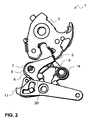
- the Fig. 1 schematically indicates a motor vehicle 2 with a door 19 on which a lock unit 1 according to the invention is provided.
- the lock unit 1 is preferably arranged in a housing 16 on which an inlet mouth 17 is provided for the lock holder 15 arranged on the body of the motor vehicle 2.
- the Fig. 1 shows the locked state of the lock unit 1, in which the rotary latch 3 has the indicated lock holder 15 securely received in the receptacle 18 provided therefor.
- the rotary latch 3 is designed with a main catch 5 and a pre-latching 4.
- the rotary latch 3 exerts a force on the first pawl 6. This force results on the one hand from the spring preload, which moves the rotary latch 3 in the opening device (white arrow), as well as a force on the lock holder 15 and the door seals acting between the door 19 and the body of the motor vehicle 2, which are compressed here.
- a blocking lever 9 is provided with a blocking lever axis 10. The first pawl axis and the blocking lever axis are arranged away from each other.
- the blocking lever 9 can now be actuated via the release lever 11 when an opening operation is to be initiated.
- the trigger lever 11 here has a trigger lever axis 13, which is arranged away from the first pawl axis 7 and the blocking lever axis 10. It is preferred that the axis of rotation of the rotary latch and the trigger lever axis 13 is arranged on different sides of an imaginary connecting line between the first pawl axis 7 and the blocking lever axis 10.
- the opening process is initiated by means of the trigger lever 11, which is pivoted counterclockwise about the trigger lever axis 13 here.
- the release lever 11 directly contacts the blocking lever 9, which thereby performs a pivoting movement in the direction of rotation 12 (clockwise).
- This will be the blocking lever 9 very quickly removed from the pivoting area or from the contact surface with the first pawl 6, so that the first pawl 6 is pushed away by the opening movement of the rotary latch and the catch can move.
- the release lever 11 also pivots the second pawl 8 during its pivoting movement. The first pawl 6 and the second pawl 8 pivot both in a clockwise direction.
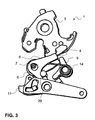
- a multi-ratchet locking a lock unit 1 shown in the three different positions.
- the rotary latch 3 can be seen.
- the first pawl 6 and the second pawl 8 can be seen, both of which are rotatably mounted on the first pawl axis 7.
- the rotatable locking lever 9 is shown.
- a return spring 14 is also provided, which acts on the blocking lever 9 and the second pawl 8. Below the pawls and the blocking lever of the release lever 11 can be seen, which is partially hidden in these representations of another lever.
- Fig. 2 When closed, as in Fig. 2 is shown, the first pawl 6 bears against the main catch 5 of the rotary latch 3. The first pawl 6 is thereby blocked by a corresponding leg of the blocking lever 9 movement. Another leg of the locking lever 9 is located on the trigger lever 11 directly.
- the second pawl 8 is pressed by means of the return spring 14 in the counterclockwise direction and is located on the stop 20 securely. With a small clearance of the trigger lever 11 is disposed in front of a corresponding leg of the second pawl 8. The actuation of the blocking lever 9 and the second pawl 8 by the release lever 11 is offset in time.
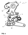
- Fig. 3 shows the position at which the second pawl 8 is engaged with the rotary latch 3.
- the rotary catch 3 has a preliminary catch 4 which rises laterally from the rotary catch 3 and which now rests against the second locking pawl 8.
- the second pawl 8 does not change its position in the main latch and pre-latch position, but that it is clearly defined via the return spring 14 and the stop 20.
- the first pawl 6 is deflected and abuts against a peripheral surface of the rotary latch 3.
- the blocking lever 9 rests in the region of the blocking surface of the first pawl 6, wherein no contact with the release lever 11, but a bias towards counterclockwise direction is provided.
- the rotary latch 3 for example. By an electric drive, further rotated counterclockwise, so that the spring-biased components are moved to the position as shown in Fig. 2 are shown as soon as the catch 3 reaches the corresponding position.
- both the first pawl 6 and the second pawl 8 are located on a peripheral portion of the rotary latch 3 outside the pre-locking and main catch. They are both pressed by a spring against the catch. In the illustrated position of the rotary latch 3, the lock holder can leave the receptacle 18 without further ado or dive into the receptacle 18 for the new closing operation.
- the invention makes it possible, in particular, to provide low-noise lock units which can be operated with high operating comfort and low force (also due to the smaller pivoting range of the pawls).
Landscapes
- Lock And Its Accessories (AREA)
Description
Die vorliegende Erfindung betrifft eine Schlosseinheit für ein Kraftfahrzeug aufweisend zumindest eine Drehfalle mit einer Vorrast und einer Hauptrast sowie zwei Sperrklinken, die die Drehfalle in bestimmten Positionen blockieren. Während der Blockierung der Drehfalle mittels der ersten Sperrklinke im Bereich der Hauptrast ist zudem ein Blockierhebel vorgesehen, der die erste Sperrklinke fixiert. Solche Schlosseinheiten mit mehrteiliger Sperrklinken sind beispielsweise aus der
Der Einsatz solcher Schlosseinheiten mit mehrteiliger Sperrklinke hat sich bereits hervorragend bewährt und zeichnet sich insbesondere durch den hohen Betätigungskomfort und die geringe Geräuschentwicklung bei der Betätigung der Schlosseinheit aus. Solche Schlosseinheiten werden insbesondere bei Türen und /oder Klappen von Kraftfahrzeugen eingesetzt.The use of such lock units with multi-part pawl has already proven itself outstanding and is characterized in particular by the high operating comfort and low noise during operation of the lock unit. Such lock units are used in particular in doors and / or flaps of motor vehicles.
Gleichwohl besteht das Bedürfnis, hier weitere Verbesserungen zu erzielen. Dabei steht insbesondere der Bedienungskomfort und ein geringer Bauraum im Vordergrund.Nevertheless, there is a need to achieve further improvements here. In particular, the ease of use and a small space is in the foreground.
Insoweit ist es Aufgabe der vorliegenden Erfindung, eine Lösung für zumindest einen Teil der mit Bezug auf den Stand der Technik geschilderten Problemstellungen anzugeben. Insbesondere soll eine Schlosseinheit angegeben werden, die platzsparend ausgeführt ist sowie schnell und leise betätigt werden kann.In that regard, it is an object of the present invention to provide a solution for at least a part of the problems described with reference to the prior art. In particular, a lock unit should be specified, which is designed to save space and can be operated quickly and quietly.
Diese Aufgaben werden gelöst mit einer Schlosseinheit gemäß den Merkmalen des Patentanspruchs 1. Weitere vorteilhafte Ausgestaltungen der Schlosseinheit sind in den abhängig formulierten Patentansprüchen angegeben. Es ist darauf hinzuweisen, dass die in den Patentansprüchen einzeln aufgeführten Merkmale in beliebiger, technologisch sinnvoller, Weise miteinander kombiniert werden können und weitere Ausgestaltungen der Erfindungen aufzeigen. Die Beschreibung, insbesondere im Zusammenhang mit den Figuren, erläutert die Erfindung weiter und gibt zusätzlich Ausführungsbeispiele an.These objects are achieved with a lock unit according to the features of
Die erfindungsgemäße Schlosseinheit für ein Kraftfahrzeug weist zumindest folgende Komponenten auf:
- eine Drehfalle mit einer Vorrast und einer Hauptrast,
- eine erste Sperrklinke mit einer ersten Sperrklinkenachse, die mit der Hauptrast in Eingriff bringbar ist,
- eine zweite Sperrklinke, die auf der ersten Sperrklinkenachse gelagert und die mit der Vorrast in Eingriff bringbar ist,
- einen Blockierhebel mit einer Blockierhebelachse, die die erste Sperrklinke fixiert, wenn diese mit der Drehfalle in Eingriff ist, und
- einen Auslösehebel zum Verschwenken zumindest des Blockierhebels,
- a catch with a pre-rest and a main catch,
- a first pawl having a first pawl axis engageable with the main catch,
- a second pawl which is mounted on the first pawl axis and which is engageable with the pre-catch,
- a blocking lever having a blocking lever axis which fixes the first pawl when it is engaged with the catch, and
- a release lever for pivoting at least the blocking lever,
Wie bereits einleitend ausgeführt, dient die Schlosseinheit insbesondere zum Verriegeln von Türen bei einem Kraftfahrzeug. Selbstverständlich kann die Schlosseinheit neben den vorstehend genannten Bauteilen zusätzliche Elemente, Hebel, Bowdenzüge, Pufferelemente und dergleichen aufweisen, hier wird sich nachfolgend auf die Ausgestaltung des Mehrklinken-Gesperres beschränkt.As already stated in the introduction, the lock unit is used in particular for locking doors in a motor vehicle. Of course, the lock unit in addition to the components mentioned above, additional elements, levers, Bowden cables, buffer elements and the like, here will be limited to the configuration of the multi-ratchet locking mechanism.
Die Drehfalle dient insbesondere zur sicheren Fixierung eines Schlosshalters bei einer Kraftfahrzeugtür. Es ist bekannt, die Drehfalle bereits in einer Position zwischen der geöffneten Stellung und geschlossenen Stellung zu sichern, so dass eine Freigabe des Schlosshalters nicht ermöglicht ist, die so genannte Vorrast-Position. Hat die Drehfalle ihre gewünschte Lage in der geschlossenen Stellung erreicht, wird sie über die so genannte Hauptrast gesichert. Vorrast und Hauptrast sind regelmäßig auf der Oberfläche bzw. der Umfangsfläche der Drehfalle vorgesehene Sperrflächen.The rotary latch is used in particular for secure fixing of a lock holder in a motor vehicle door. It is known to secure the catch already in a position between the open position and closed position, so that a Release of the lock holder is not possible, the so-called pre-locking position. If the catch has reached its desired position in the closed position, it is secured by the so-called main catch. Pre-rest and main rest are regularly provided on the surface or the peripheral surface of the catch locking surfaces.
Bevorzugt ist, dass die Drehfalle, die erste Sperrklinke, die zweite Sperrklinke, der Blockierhebel und der Auslösehebel einen metallischen Grundkörper aufweisen und Stanzbauteile sind.It is preferred that the rotary latch, the first pawl, the second pawl, the blocking lever and the release lever have a metallic base body and are stamped components.
Bei dem hier vorgeschlagenen Gesperre sind die erste Sperrklinke und die zweite Sperrklinke auch an einer gemeinsamen ersten Sperrklinkendrehachse drehbar gelagert, wobei diese gegebenenfalls mit einer Feder vorgespannt sein können. Die erste Sperrklinke dient zum Arretieren der Drehfalle in der Hauptrast (Hauptrast-Sperrklinke) und die zweite Sperrklinke dient zur Arretierung der Drehfalle an der Vorrast (Vorrast-Sperrklinke). Das bedeutet insbesondere, dass die erste Sperrklinke und die zweite Sperrklinke zu unterschiedlichen Zeitpunkten bzw. bei unterschiedlichen Positionen der Drehfalle mit der Drehfalle in Eingriff sind.In the locking mechanism proposed here, the first pawl and the second pawl are also rotatably mounted on a common first pawl rotation axis, which may optionally be biased by a spring. The first pawl serves to lock the catch in the main catch (main catch pawl) and the second pawl is used to lock the catch on the Vorrast (pre-locking pawl). This means in particular that the first pawl and the second pawl are engaged at different times or at different positions of the rotary latch with the rotary latch.
Der Eingriff zwischen der ersten Sperrklinke und der Drehfalle ist dabei derart, dass die erste Sperrklinke die Drehfalle nicht selbst bzw. nicht alleine bewegungsblockiert. Vielmehr ist der Eingriff zwischen erster Sperrklinke und Drehfalle derart, dass die Drehfalle auf die erste Sperrklinke eine Kraft ausübt, so dass diese in eine die Drehfalle freigebende Stellung hin bewegt wird. Um nunmehr gleichwohl zu gewährleisten, dass die erste Sperrklinke an der Hauptrast der Drehfalle in der geschlossenen Stellung sicher anliegt, wird eine solche Verschwenkung der ersten Sperrklinke mit dem Blockierhebel unterbunden, der die erste Sperrklinke gegen die Drehfalle bzw. Hauptrast drückt bzw. hält.The engagement between the first pawl and the rotary latch is such that the first pawl does not block the catch itself or movement alone. Rather, the engagement between the first pawl and the rotary latch is such that the rotary latch exerts a force on the first pawl, so that it is moved into a position releasing the rotary latch. In order nevertheless to ensure that the first pawl rests securely against the main catch of the rotary latch in the closed position, such pivoting of the first pawl with the blocking lever is suppressed, which presses or holds the first pawl against the rotary latch or main catch.
Soll nunmehr ein Öffnungsvorgang initiiert werden, so ist zunächst der Blockierhebel von der ersten Sperrklinke abzuheben, sodass diese von der Drehfalle selbst weggedrückt werden kann. Zum Verschwenken des Blockierhebels ist demnach ein Auslösehebel vorgesehen, mit dem der Blockierhebel bei der Initiierung des Öffnungsvorgangs verschwenkt werden kann.If now an opening operation to be initiated, so first the blocking lever is lifted from the first pawl, so that it can be pushed away from the catch itself. For the pivoting of the blocking lever, therefore, a release lever is provided, with which the blocking lever can be pivoted in the initiation of the opening process.
Die erste Sperrklinke, die zweite Sperrklinke und zumindest noch der Blockierhebel sind als Schwenkhebel ausgeführt, das heißt, diese lassen sich (in einem begrenzten Verschwenkbereich) um ihre Achse verschwenken. Für den Öffnungsvorgang ist hier nun vorgeschlagen worden, diese Bauteile so anzuordnen, dass die erste Sperrklinke und der Blockierhebel mit in derselben Drehrichtung verschwenkt werden. Führt die erste Sperrklinke beim Abheben von der Hauptrast der Drehfalle eine Verschwenkung in eine bestimmte Drehrichtung (z.B. Uhrzeigersinn) aus, so erfolgt die Anordnung des Blockierhebels bzw. des Auslösehebels in der Weise, dass der Blockierhebel ebenfalls mit dieser Drehrichtung (Uhrzeigersinn) verschwenkt wird. Damit kann insbesondere erreicht werden, dass der Blockierhebel bereits nach einem kurzen Verschwenkweg aus dem Verschwenkbereich der ersten Sperrklinke entfernt werden kann, sodass hier mit besonders geringen Bewegungen die gewünschte Freigabe der Drehfalle erreicht werden kann.The first pawl, the second pawl and at least the locking lever are designed as a pivot lever, that is, these can be pivoted (in a limited pivoting range) about its axis. For the opening process has now been proposed here, these components to be arranged so that the first pawl and the blocking lever are pivoted in the same direction. If the first pawl, when lifted from the main catch of the rotary latch, pivots in a certain direction of rotation (e.g., clockwise), the blocking lever or trip lever is arranged such that the blocking lever is also pivoted in this clockwise direction. This can be achieved, in particular, that the blocking lever can be removed after a short Verschwenkweg from the pivoting range of the first pawl, so that here with very small movements, the desired release of the catch can be achieved.
Darüber hinaus wird als vorteilhaft angesehen, dass der Auslösehebel beim Öffnungsvorgang die zweite Sperrklinke verschwenkt. Die Verschwenkung der zweiten Sperrklinke mit dem Auslösehebel kann zeitgleich mit dem Verschwenken des Blockierhebels erfolgen oder gegebenenfalls zeitlich verzögert. Zu diesem Zweck kann der Auslösehebel mehrere Schenkel aufweisen, die direkt anliegen und/oder mit einem Spiel zum Blockierhebel bzw. der zweiten Sperrklinke in der geschlossenen Stellung in der Schlosseinheit positioniert sind.In addition, it is considered advantageous that the release lever pivots the second pawl during the opening process. The pivoting of the second pawl with the release lever can take place at the same time as the pivoting of the blocking lever or optionally delayed. For this purpose, the release lever may have a plurality of legs, which lie directly and / or are positioned with a clearance to the blocking lever or the second pawl in the closed position in the lock unit.
Gerade in diesem Zusammenhang wird als vorteilhaft angesehen, dass der Auslösehebel den Blockierhebel und die zweite Sperrklinke mit der selben Drehrichtung gleichzeitig verschwenkt. Auf diese Weise kann eine besonders platzsparende Anordnung der beiden Sperrklinken, des Blockierhebels und des Auslösehebels erreicht werden, indem beispielweise der Auslösehebel zwischen den Sperrklinken und dem Blockierhebel angeordnet ist. Dabei ergibt sich insbesondere die Funktion, dass der Blockierhebel durch den Auslösehebel in der gewünschten Drehrichtung bewegt wird, gleichzeitig (oder etwas verzögert) auch die zweite Sperrklinke in derselben Drehrichtung und durch den Auslösehebel verschwenkt wird und zudem die erste Sperrklinke durch die Krafteinwirkung ausgehend von der Drehfalle (3) (die federvorgespannt ist) ebenfalls in dieselbe Drehrichtung verschwenkt wird.Especially in this context is considered advantageous that the release lever pivots the blocking lever and the second pawl with the same direction of rotation simultaneously. In this way, a particularly space-saving arrangement of the two pawls, the blocking lever and the release lever can be achieved, for example, by the release lever between the pawls and the blocking lever is arranged. This results in particular the function that the blocking lever is moved by the release lever in the desired direction, simultaneously (or slightly delayed) and the second pawl is pivoted in the same direction and by the release lever and also the first pawl by the force starting from the Rotary latch (3) (which is spring-biased) is also pivoted in the same direction of rotation.
Darüber hinaus wird als vorteilhaft angesehen, dass der Auslösehebel um eine Auslösehebelachse drehbar ist. In diesem Fall ist der Auslösehebel ebenfalls als verschwenkbarer Hebel ausgeführt. Um hier wiederum eine besonders platzsparende Anordnung der diversen Hebel zu erreichen, verschwenkt dieser mit einer Drehrichtung, die der Drehrichtung der ersten Sperrklinke und des Blockierhebels (und der zweiten Sperrklinke) entgegengesetzt ist.In addition, it is considered advantageous that the release lever is rotatable about a trigger lever axis. In this case, the release lever is also designed as a pivotable lever. In order to achieve again a particularly space-saving arrangement of the various levers, this pivots with a direction of rotation, which is opposite to the direction of rotation of the first pawl and the blocking lever (and the second pawl).
Außerdem wird als vorteilhaft angesehen, dass die zweite Sperrklinke mit einer entgegen ihrer Drehrichtung beim Öffnungsvorgang wirkenden Rückstellfeder kontaktiert ist. Die Rückstellfeder wirkt also auf die zweite Sperrklinke so ein, dass diese permanent hin zur Drehfalle gedrückt wird und somit eine sichere Anlage an einem externen Anschlag und/oder der Drehfalle realisiert ist. Jedenfalls soll so auch erreicht werden, dass die zweite Sperrklinke beim Schließvorgang der Schlosseinheit unmittelbar hin zur Vorrast bewegt wird, sobald die Drehfalle den damit erforderlichen Verschwenkungsgrad erreicht hat. Die Rückstellfeder ist bevorzugt ausgehend von der zweiten Sperrklinke gegenüberliegend zur Drehfalle gelagert.It is also considered advantageous that the second pawl is contacted with a counter to its direction of rotation during the opening operation acting return spring. The return spring thus acts on the second pawl so that it is pressed permanently towards the catch and thus a secure contact with an external stop and / or the catch is realized. In any case, should also be achieved so that the second pawl is moved during the closing process of the lock unit directly to the pre-rest, as soon as the catch has reached the required pivoting degree. The return spring is preferably mounted on the basis of the second pawl opposite to the rotary latch.
Schließlich wird auch ein Kraftfahrzeug vorgeschlagen, das wenigstens eine hier erfindungsgemäß beschriebene Schlosseinheit aufweist. Eine solche Schlosseinheit ist, insbesondere zum Verriegeln von Türen und/oder Klappen derartiger Kraftfahrzeuge vorgesehen.Finally, a motor vehicle is proposed which has at least one lock unit described here according to the invention. Such a lock unit is provided, in particular for locking doors and / or flaps of such motor vehicles.
Die Erfindung sowie das technische Umfeld werden nun anhand der Figuren näher erläutert. Es ist darauf hinzuweisen, dass die Figuren besonders bevorzugte Ausführungsvarianten der Erfindung aufzeigen, diese jedoch nicht darauf beschränkt ist. Es zeigen schematisch:
- Fig. 1:
- eine erste Ausführungsvariante einer erfindungsgemäßen Schlosseinheit in verriegeltem Zustand;
- Fig. 2:
- eine Ausführungsvariante der Schlosseinheit, wenn die erste Sperrklinke im Eingriff mit der Hauptrast an der Drehfalle ist;
- Fig. 3:
- die Ausfübrungsvariante aus
Fig. 2 , wobei die zweite Sperrklinke mit der Vorrast der Drehfalle in Eingriff ist; und - Fig. 4:
- die Ausführungsvariante aus
Fig. 2 und3 in der offenen Stellung.
- Fig. 1:
- a first embodiment of a lock unit according to the invention in the locked state;
- Fig. 2:
- an embodiment of the lock unit when the first pawl is engaged with the main catch on the rotary latch;
- 3:
- the Ausfübrungsvariante
Fig. 2 wherein the second pawl is engaged with the latch of the catch; and - 4:
- the embodiment variant
Fig. 2 and3 in the open position.
Die
Im Verschwenkbereich der Drehfalle 3 sind nunmehr zwei Sperrklinken vorgesehen, die beide auf der ersten Sperrklinkenachse 7 drehbar gelagert sind. Von oben gut zu erkennen ist die zweite Sperrklinke 8, die in diesem verriegelten Zustand keinen Kontakt hin zur Drehfalle 3 hat. Darunter befindet sich die erste Sperrklinke 6, die direkt an der Hauptrast 5 der Drehfalle 3 anliegt.In the pivoting region of the
Die Drehfalle 3 übt eine Kraft auf die erste Sperrklinke 6 aus. Diese Kraft resultiert einerseits aus der Federvorspannung, die die Drehfalle 3 in die Öffnungsvorrichtung (weißer Pfeil) bewegt, sowie eine Krafteinleitung über den Schlosshalter 15 bzw. die zwischen der Tür 19 und der Karosserie des Kraftfahrzeugs 2 wirkenden Türdichtungen, die hier zusammengepresst sind. Um nunmehr zu verhindern, dass die erste Sperrklinke 6 von der Drehfalle 3 weggedrückt wird, ist ein Blockierhebel 9 mit einer Blockierhebelachse 10 vorgesehen. Die erste Sperrklinkenachse und die Blockierhebelachse sind voneinander entfernt angeordnet.The
Der Blockierhebel 9 kann nunmehr über den Auslösehebel 11 betätigt werden, wenn ein Öffnungsvorgang initiiert werden soll. Der Auslösehebel 11 weist hier eine Auslösehebelachse 13 auf, die entfernt von der ersten Sperrklinkenachse 7 und der Blockierhebelachse 10 angeordnet ist. Bevorzugt ist, dass die Drehachse der Drehfalle und die Auslösehebelachse 13 auf verschiedenen Seiten einer imaginären Verbindungslinie zwischen erster Sperrklinkenachse 7 und Blockierhebelachse 10 angeordnet ist.The blocking
Für den Öffnungsvorgang sind nunmehr auch die Drehrichtungen 12 der Bauteile der Schlosseinheit 1 durch schwarze Pfeile gekennzeichnet. So wird der Öffnungsvorgang mittels des Auslösehebels 11 initiiert, der hier gegen den Uhrzeigersinn um die Auslösehebelachse 13 verschwenkt wird. Dabei kontaktiert der Auslösehebel 11 direkt den Blockierhebel 9, der dadurch eine Verschwenkbewegung in Drehrichtung 12 (im Uhrzeigersinn) ausführt. Dadurch wird der Blockierhebel 9 sehr schnell aus dem Verschwenkbereich bzw. von der Kontaktfläche mit der ersten Sperrklinke 6 entfernt, sodass die erste Sperrklinke 6 durch die Öffnungsbewegung der Drehfalle weggedrückt wird und die Drehfalle sich bewegen kann. Zusätzlich ist hier zudem angedeutet, dass der Auslösehebel 11 bei seiner Schwenkbewegung auch die zweite Sperrklinke 8 verschwenkt. Die erste Sperrklinke 6 und die zweite Sperrklinke 8 verschwenken dabei beide im Uhrzeigersinn.For the opening process now the directions of
In den
Im geschlossenen Zustand, wie er in
In
Mit der Erfindung lassen sich insbesondere geräuscharme Schlosseinheiten bereit stellen, die sich (auch aufgrund des kleineren Verschwenkbereichs der Klinken) mit hohem Betätigungskomfort und geringer Kraft bedienen lassen.The invention makes it possible, in particular, to provide low-noise lock units which can be operated with high operating comfort and low force (also due to the smaller pivoting range of the pawls).
- 11
- Schlosseinheitlock unit
- 22
- Kraftfahrzeugmotor vehicle
- 33
- Drehfallecatch
- 44
- Vorrastfirst position
- 55
- Hauptrastprimary position
- 66
- erste Sperrklinkefirst pawl
- 77
- erste Sperrklinkenachsefirst pawl axis
- 88th
- zweite Sperrklinkesecond pawl
- 99
- Blockierhebelblocking lever
- 1010
- BlockierhebelachseBlocking lever axis
- 1111
- Auslösehebelsear
- 1212
- Drehrichtungdirection of rotation
- 1313
- AuslösehebelachseRelease lever axis
- 1414
- RückstellfederReturn spring
- 1515
- SchlosshalterCastle holder
- 1616
- Gehäusecasing
- 1717
- Einlaufmaulinlet opening
- 1818
- Aufnahmeadmission
- 1919
- Türdoor
- 2020
- Anschlagattack
Claims (6)
- Lock unit (1) for a motor vehicle (2) comprising at least- a rotary catch (3) having a preliminary catch (4) and a main catch (5),- a first pawl (6) with a first pawl rotational axis (7), which can be engaged with the main catch (5),- a second pawl (8), which is mounted on the first pawl rotational axis (7) and can be engaged with the preliminary catch (4),- a blocking lever (9) with a blocking lever axis (10), which fixes the first pawl (6) when the latter is engaged with the rotary catch (3) and- a triggering lever (11) for swiveling at least the blocking lever (10),wherein the triggering lever (11) cooperates during the opening process with the blocking lever (9), such that the first pawl (6) and the blocking lever (9) are swiveled with the same rotational direction (12).
- Lock unit (1) according to claim 1, in which the triggering lever (11) swivels the second pawl (8) during the opening process.
- Lock unit (1) according to claim 2, in which the triggering lever (11) simultaneously swivels the blocking lever (9) and the second pawl (8) with the same direction of rotation (12).
- Lock unit (1) according to one of the above claims in which the triggering lever (11) is rotatable around a triggering lever axis (13).
- Lock unit (1) according to one of the above claims in which the second pawl (8) is in contact with a return spring (14) acting against its direction of rotation (12) during the opening process.
- Motor vehicle (2) containing at least one lock unit (1) according to one of the above claims.
Applications Claiming Priority (2)
| Application Number | Priority Date | Filing Date | Title |
|---|---|---|---|
| DE200810048712 DE102008048712A1 (en) | 2008-09-24 | 2008-09-24 | Locking unit with multi-ratchet lock |
| PCT/DE2009/001320 WO2010034295A1 (en) | 2008-09-24 | 2009-09-18 | Lock unit having a multi-pawl locking mechanism |
Publications (2)
| Publication Number | Publication Date |
|---|---|
| EP2326780A1 EP2326780A1 (en) | 2011-06-01 |
| EP2326780B1 true EP2326780B1 (en) | 2013-04-10 |
Family
ID=41665199
Family Applications (1)
| Application Number | Title | Priority Date | Filing Date |
|---|---|---|---|
| EP20090748949 Not-in-force EP2326780B1 (en) | 2008-09-24 | 2009-09-18 | Lock unit having a multi-pawl locking mechanism |
Country Status (7)
| Country | Link |
|---|---|
| US (1) | US8827329B2 (en) |
| EP (1) | EP2326780B1 (en) |
| JP (1) | JP5351273B2 (en) |
| CN (1) | CN102089488B (en) |
| BR (1) | BRPI0913492B1 (en) |
| DE (1) | DE102008048712A1 (en) |
| WO (1) | WO2010034295A1 (en) |
Cited By (1)
| Publication number | Priority date | Publication date | Assignee | Title |
|---|---|---|---|---|
| DE102020105836A1 (en) | 2020-03-04 | 2021-09-09 | Brose Schließsysteme GmbH & Co. Kommanditgesellschaft | Motor vehicle lock |
Families Citing this family (46)
| Publication number | Priority date | Publication date | Assignee | Title |
|---|---|---|---|---|
| DE202008012706U1 (en) * | 2008-09-24 | 2008-12-18 | Kiekert Ag | Lock unit with multipart pawl and spring-loaded locking pawl |
| DE102010003483B4 (en) * | 2009-06-12 | 2019-08-01 | Kiekert Ag | Lock with positive guide for pawl |
| DE102011100552A1 (en) * | 2010-05-05 | 2011-11-10 | Inteva Products, Llc | Vehicle door lock assembly for movable panels such as door or bonnet of motor vehicle, comprises fork shaft, which is fixed to lock assembly in movable manner, where fork shaft is moved between latched position and unlatched position |
| GB2480860B (en) * | 2010-06-04 | 2014-05-21 | Body Systems Usa Llc | Latch assembly |
| DE102010030595A1 (en) * | 2010-06-28 | 2011-12-29 | Kiekert Ag | Lock for motor vehicle or building |
| DE102011010816A1 (en) * | 2011-02-09 | 2012-08-09 | Kiekert Ag | Motor vehicle door lock |
| DE102011004170B4 (en) * | 2011-02-15 | 2012-09-13 | Kiekert Ag | Lock for a flap or door |
| DE202011004952U1 (en) * | 2011-04-06 | 2012-07-09 | BROSE SCHLIEßSYSTEME GMBH & CO. KG | Motor vehicle lock |
| JP5437309B2 (en) * | 2011-04-22 | 2014-03-12 | アイシン精機株式会社 | Rotating lever position holding device and vehicular door lock device including the rotating lever position holding device |
| CN103998704B (en) * | 2011-10-21 | 2017-02-22 | 开开特股份公司 | Lock device having a multi-part pawl |
| DE102012203734A1 (en) * | 2012-03-09 | 2013-09-12 | Kiekert Ag | Lock for a flap or door |
| DE102012103383A1 (en) * | 2012-04-18 | 2013-10-24 | Deutsches Zentrum für Luft- und Raumfahrt e.V. | Method for producing a carrier substrate, carrier substrate and electrochemical device |
| DE102012207442A1 (en) * | 2012-05-04 | 2013-11-07 | Kiekert Ag | Lock for a flap or door |
| DE102012207443A1 (en) * | 2012-05-04 | 2013-11-07 | Kiekert Ag | Lock for a flap or door |
| DE102012207440A1 (en) * | 2012-05-04 | 2013-11-07 | Kiekert Ag | Lock for a flap or door |
| DE102012207441A1 (en) * | 2012-05-04 | 2013-11-07 | Kiekert Ag | Lock for a flap or door |
| DE102012023236A1 (en) * | 2012-11-28 | 2014-05-28 | Kiekert Aktiengesellschaft | Motor vehicle door lock |
| DE102012024379A1 (en) * | 2012-12-12 | 2014-03-27 | Kiekert Aktiengesellschaft | Method for producing motor vehicle locks with twisted locking part edge |
| DE102012024285A1 (en) * | 2012-12-12 | 2014-06-12 | Kiekert Ag | Motor vehicle door lock |
| DE102012024303A1 (en) * | 2012-12-12 | 2014-06-12 | Kiekert Aktiengesellschaft | Motor vehicle door lock |
| DE102012025053A1 (en) * | 2012-12-21 | 2014-06-26 | BROSE SCHLIEßSYSTEME GMBH & CO. KG | Motor vehicle lock |
| US9212509B2 (en) * | 2013-03-27 | 2015-12-15 | Kiekert Ag | Locking mechanism |
| DE102013103245A1 (en) | 2013-03-28 | 2014-10-02 | Kiekert Aktiengesellschaft | Motor vehicle door lock |
| JP6453356B2 (en) * | 2013-11-22 | 2019-01-16 | ゲコム コーポレーション | Vehicle hood latch |
| CN103603561B (en) * | 2013-11-30 | 2016-06-29 | 烟台三环锁业集团有限公司 | The double; two of automobile engine cover lock draw opening structure |
| DE102014001789A1 (en) * | 2014-02-12 | 2015-08-13 | Kiekert Aktiengesellschaft | Krahftfahrzeugtürschloss |
| KR101560979B1 (en) * | 2014-05-30 | 2015-10-15 | 평화정공 주식회사 | Hood latch having dual unlocking function |
| KR101673705B1 (en) | 2014-12-02 | 2016-11-07 | 현대자동차주식회사 | Door latch device for vehicle |
| US20160168883A1 (en) * | 2014-12-15 | 2016-06-16 | GM Global Technology Operations LLC | Double pull action vehicle hood latch |
| WO2016142771A1 (en) * | 2015-03-12 | 2016-09-15 | Kiekert Ag | Motor vehicle door lock, particularly a backrest lock on a motor vehicle seat |
| US10941592B2 (en) * | 2015-05-21 | 2021-03-09 | Magna Closures Inc. | Latch with double actuation and method of construction thereof |
| WO2016206665A1 (en) * | 2015-06-22 | 2016-12-29 | Kiekert Ag | Motor vehicle door lock |
| CN109339599B (en) * | 2016-01-29 | 2021-03-12 | 开开特股份公司 | Motor vehicle lock |
| DE102017209376A1 (en) * | 2016-06-07 | 2017-12-07 | Magna Closures Inc. | Vehicle lock latch assembly with double pawl latch mechanism |
| US10808437B2 (en) * | 2017-07-21 | 2020-10-20 | Kiekert Ag | Motor vehicle door latch with primary and secondary pawl |
| DE102017122803A1 (en) * | 2017-09-29 | 2019-04-04 | Brose Schließsysteme GmbH & Co. Kommanditgesellschaft | Motor vehicle lock |
| JP6891801B2 (en) * | 2017-12-25 | 2021-06-18 | トヨタ自動車株式会社 | Vehicle door lock device |
| CN114673412B (en) * | 2018-02-08 | 2023-08-29 | 麦格纳覆盖件有限公司 | Closure latch assembly with latch mechanism and method of operating the same |
| DE102018113595A1 (en) * | 2018-06-07 | 2019-12-12 | Kiekert Ag | Motor vehicle door lock |
| US11421455B2 (en) * | 2018-10-03 | 2022-08-23 | Inteva Products, Llc | Hood latch for motor vehicle having under hood storage |
| DE102019123837A1 (en) * | 2018-10-22 | 2020-04-23 | Kiekert Aktiengesellschaft | Motor vehicle lock |
| US10864831B2 (en) * | 2019-01-11 | 2020-12-15 | Kiekert Ag | Motor vehicle latch, in particular, backrest latch on a motor vehicle seat |
| US11339591B2 (en) * | 2019-02-12 | 2022-05-24 | GM Global Technology Operations LLC | Latch assembly having self re-latching feature |
| DE102019131179A1 (en) * | 2019-11-19 | 2021-05-20 | Kiekert Aktiengesellschaft | Motor vehicle lock |
| DE102020133537A1 (en) * | 2020-12-15 | 2022-06-15 | Brose Schließsysteme GmbH & Co. Kommanditgesellschaft | motor vehicle lock |
| WO2022245866A1 (en) * | 2021-05-17 | 2022-11-24 | Motown Engineering, Inc. | Vehicle door latch |
Family Cites Families (13)
| Publication number | Priority date | Publication date | Assignee | Title |
|---|---|---|---|---|
| DE3801581C1 (en) * | 1988-01-21 | 1988-10-13 | Bomoro Bocklenberg & Motte Gmbh & Co Kg, 5600 Wuppertal, De | |
| JP2504946Y2 (en) * | 1990-05-29 | 1996-07-24 | 三菱自動車工業株式会社 | Door lock device |
| CN1058068C (en) * | 1994-11-10 | 2000-11-01 | 三井金属矿业株式会社 | Vehicle door lock device |
| DE19937405B4 (en) * | 1999-08-07 | 2011-06-01 | Bayerische Motoren Werke Aktiengesellschaft | Closure for a hinged hood of a motor vehicle |
| DE20104625U1 (en) * | 2001-03-17 | 2002-08-01 | Bayerische Motoren Werke AG, 80809 München | Motor vehicle door lock |
| EP1380715A1 (en) | 2002-07-12 | 2004-01-14 | SO.GE.MI.- S.p.A. | Safety lock for car bonnets or doors |
| DE10336049A1 (en) * | 2003-08-01 | 2005-02-17 | Kiekert Ag | Motor vehicle door lock |
| KR20050032210A (en) * | 2003-10-01 | 2005-04-07 | 기아자동차주식회사 | Door latch structure for a vehicle |
| CN2809129Y (en) | 2005-01-18 | 2006-08-23 | 鑫田集团有限公司 | Car door lock |
| DE102007003948A1 (en) * | 2006-11-22 | 2008-05-29 | Kiekert Ag | Locking unit with multipart pawl |
| DE102008035607A1 (en) * | 2008-07-31 | 2010-02-04 | Kiekert Ag | Lock unit with two pawls and position detectors |
| US8235428B2 (en) * | 2009-07-14 | 2012-08-07 | Kiekert Ag | Lock unit having a slotted pawl |
| US8596696B2 (en) * | 2010-02-24 | 2013-12-03 | Magna Closures S.P.A. | Vehicular latch with single notch ratchet |
-
2008
- 2008-09-24 DE DE200810048712 patent/DE102008048712A1/en not_active Withdrawn
-
2009
- 2009-09-18 US US13/120,156 patent/US8827329B2/en active Active
- 2009-09-18 WO PCT/DE2009/001320 patent/WO2010034295A1/en active Application Filing
- 2009-09-18 JP JP2011528185A patent/JP5351273B2/en not_active Expired - Fee Related
- 2009-09-18 CN CN2009801371523A patent/CN102089488B/en not_active Expired - Fee Related
- 2009-09-18 BR BRPI0913492-1A patent/BRPI0913492B1/en not_active IP Right Cessation
- 2009-09-18 EP EP20090748949 patent/EP2326780B1/en not_active Not-in-force
Cited By (1)
| Publication number | Priority date | Publication date | Assignee | Title |
|---|---|---|---|---|
| DE102020105836A1 (en) | 2020-03-04 | 2021-09-09 | Brose Schließsysteme GmbH & Co. Kommanditgesellschaft | Motor vehicle lock |
Also Published As
| Publication number | Publication date |
|---|---|
| DE102008048712A1 (en) | 2010-03-25 |
| US20110169280A1 (en) | 2011-07-14 |
| US8827329B2 (en) | 2014-09-09 |
| EP2326780A1 (en) | 2011-06-01 |
| CN102089488B (en) | 2013-08-21 |
| CN102089488A (en) | 2011-06-08 |
| JP2012503723A (en) | 2012-02-09 |
| BRPI0913492B1 (en) | 2019-02-12 |
| WO2010034295A1 (en) | 2010-04-01 |
| JP5351273B2 (en) | 2013-11-27 |
| BRPI0913492A2 (en) | 2018-01-09 |
Similar Documents
| Publication | Publication Date | Title |
|---|---|---|
| EP2326780B1 (en) | Lock unit having a multi-pawl locking mechanism | |
| EP2326781B1 (en) | Lock unit having a multi-part pawl and a spring-loaded blocking pawl | |
| EP2347071B1 (en) | Lock unit having a multi-pawl locking mechanism | |
| EP2089599B1 (en) | Lock device having a multi-part pawl | |
| EP2291568B1 (en) | Closing device comprising two pawls and a motor-driven actuating mechanism | |
| EP2823120B1 (en) | Lock for a panel or door | |
| EP2964859B1 (en) | Lock for a motor vehicle | |
| EP2929114B1 (en) | Lock for a flap or door | |
| EP2291571B1 (en) | Closing device comprising a detent spring | |
| EP2929112B1 (en) | Lock for a hatch or a door | |
| EP2358958B1 (en) | Multi-latch lock with catch hook | |
| EP1460211A2 (en) | Motor vehicle lock | |
| DE102014001490A1 (en) | Lock for a motor vehicle | |
| WO2015090286A1 (en) | Lock for a motor vehicle | |
| DE102013110756A1 (en) | Motor vehicle door lock | |
| EP3784855B1 (en) | Motor vehicle lock | |
| DE102010061427A1 (en) | Rotary latch lock for use in motor car to hold door or flap in closed position, has locking pawl exerting pre-catch force and rotational torque in release direction on pre-locking position against displacement into releasing position | |
| EP2545234B1 (en) | Motor vehicle lock having force transmission onto the lock case | |
| EP3179021B1 (en) | Door handle assembly for a motor vehicle | |
| DE102012207443A1 (en) | Lock for a flap or door | |
| DE102012207440A1 (en) | Lock for a flap or door | |
| DE102008034638A1 (en) | Locking device for motor vehicle, comprises blocking lever, rotary latch and bolt with pawl rotational axis, where rotary latch introduces pivoting torque in bolt in locked state of locking device | |
| DE102008039240A1 (en) | Closing device for locking and unlocking of e.g. movable door, in motor vehicle, has triggering lever moved to cooperate with driving dog of detent, and detent spring forming stop between dog and triggering lever during cooperation of lever | |
| EP3679208A1 (en) | Motor vehicle door lock | |
| EP3385482A1 (en) | Lock assembly for a vehicle |
Legal Events
| Date | Code | Title | Description |
|---|---|---|---|
| PUAI | Public reference made under article 153(3) epc to a published international application that has entered the european phase |
Free format text: ORIGINAL CODE: 0009012 |
|
| 17P | Request for examination filed |
Effective date: 20110224 |
|
| AK | Designated contracting states |
Kind code of ref document: A1 Designated state(s): AT BE BG CH CY CZ DE DK EE ES FI FR GB GR HR HU IE IS IT LI LT LU LV MC MK MT NL NO PL PT RO SE SI SK SM TR |
|
| AX | Request for extension of the european patent |
Extension state: AL BA RS |
|
| RIN1 | Information on inventor provided before grant (corrected) |
Inventor name: SCHOLZ, MICHAEL Inventor name: GOETZ, OLIVER |
|
| RIN1 | Information on inventor provided before grant (corrected) |
Inventor name: GOETZ, OLIVER Inventor name: SCHOLZ, MICHAEL |
|
| DAX | Request for extension of the european patent (deleted) | ||
| GRAP | Despatch of communication of intention to grant a patent |
Free format text: ORIGINAL CODE: EPIDOSNIGR1 |
|
| GRAS | Grant fee paid |
Free format text: ORIGINAL CODE: EPIDOSNIGR3 |
|
| GRAA | (expected) grant |
Free format text: ORIGINAL CODE: 0009210 |
|
| AK | Designated contracting states |
Kind code of ref document: B1 Designated state(s): AT BE BG CH CY CZ DE DK EE ES FI FR GB GR HR HU IE IS IT LI LT LU LV MC MK MT NL NO PL PT RO SE SI SK SM TR |
|
| REG | Reference to a national code |
Ref country code: GB Ref legal event code: FG4D Free format text: NOT ENGLISH |
|
| REG | Reference to a national code |
Ref country code: CH Ref legal event code: EP Ref country code: AT Ref legal event code: REF Ref document number: 606131 Country of ref document: AT Kind code of ref document: T Effective date: 20130415 |
|
| REG | Reference to a national code |
Ref country code: IE Ref legal event code: FG4D Free format text: LANGUAGE OF EP DOCUMENT: GERMAN |
|
| REG | Reference to a national code |
Ref country code: DE Ref legal event code: R096 Ref document number: 502009006820 Country of ref document: DE Effective date: 20130606 |
|
| PG25 | Lapsed in a contracting state [announced via postgrant information from national office to epo] |
Ref country code: SI Free format text: LAPSE BECAUSE OF FAILURE TO SUBMIT A TRANSLATION OF THE DESCRIPTION OR TO PAY THE FEE WITHIN THE PRESCRIBED TIME-LIMIT Effective date: 20130410 |
|
| REG | Reference to a national code |
Ref country code: LT Ref legal event code: MG4D Ref country code: NL Ref legal event code: VDEP Effective date: 20130410 |
|
| PG25 | Lapsed in a contracting state [announced via postgrant information from national office to epo] |
Ref country code: NO Free format text: LAPSE BECAUSE OF FAILURE TO SUBMIT A TRANSLATION OF THE DESCRIPTION OR TO PAY THE FEE WITHIN THE PRESCRIBED TIME-LIMIT Effective date: 20130710 Ref country code: SE Free format text: LAPSE BECAUSE OF FAILURE TO SUBMIT A TRANSLATION OF THE DESCRIPTION OR TO PAY THE FEE WITHIN THE PRESCRIBED TIME-LIMIT Effective date: 20130410 Ref country code: FI Free format text: LAPSE BECAUSE OF FAILURE TO SUBMIT A TRANSLATION OF THE DESCRIPTION OR TO PAY THE FEE WITHIN THE PRESCRIBED TIME-LIMIT Effective date: 20130410 Ref country code: GR Free format text: LAPSE BECAUSE OF FAILURE TO SUBMIT A TRANSLATION OF THE DESCRIPTION OR TO PAY THE FEE WITHIN THE PRESCRIBED TIME-LIMIT Effective date: 20130711 Ref country code: PT Free format text: LAPSE BECAUSE OF FAILURE TO SUBMIT A TRANSLATION OF THE DESCRIPTION OR TO PAY THE FEE WITHIN THE PRESCRIBED TIME-LIMIT Effective date: 20130812 Ref country code: NL Free format text: LAPSE BECAUSE OF FAILURE TO SUBMIT A TRANSLATION OF THE DESCRIPTION OR TO PAY THE FEE WITHIN THE PRESCRIBED TIME-LIMIT Effective date: 20130410 Ref country code: IS Free format text: LAPSE BECAUSE OF FAILURE TO SUBMIT A TRANSLATION OF THE DESCRIPTION OR TO PAY THE FEE WITHIN THE PRESCRIBED TIME-LIMIT Effective date: 20130810 Ref country code: LT Free format text: LAPSE BECAUSE OF FAILURE TO SUBMIT A TRANSLATION OF THE DESCRIPTION OR TO PAY THE FEE WITHIN THE PRESCRIBED TIME-LIMIT Effective date: 20130410 Ref country code: ES Free format text: LAPSE BECAUSE OF FAILURE TO SUBMIT A TRANSLATION OF THE DESCRIPTION OR TO PAY THE FEE WITHIN THE PRESCRIBED TIME-LIMIT Effective date: 20130721 |
|
| PG25 | Lapsed in a contracting state [announced via postgrant information from national office to epo] |
Ref country code: CY Free format text: LAPSE BECAUSE OF FAILURE TO SUBMIT A TRANSLATION OF THE DESCRIPTION OR TO PAY THE FEE WITHIN THE PRESCRIBED TIME-LIMIT Effective date: 20130410 Ref country code: HR Free format text: LAPSE BECAUSE OF FAILURE TO SUBMIT A TRANSLATION OF THE DESCRIPTION OR TO PAY THE FEE WITHIN THE PRESCRIBED TIME-LIMIT Effective date: 20130410 Ref country code: LV Free format text: LAPSE BECAUSE OF FAILURE TO SUBMIT A TRANSLATION OF THE DESCRIPTION OR TO PAY THE FEE WITHIN THE PRESCRIBED TIME-LIMIT Effective date: 20130410 Ref country code: PL Free format text: LAPSE BECAUSE OF FAILURE TO SUBMIT A TRANSLATION OF THE DESCRIPTION OR TO PAY THE FEE WITHIN THE PRESCRIBED TIME-LIMIT Effective date: 20130410 Ref country code: BG Free format text: LAPSE BECAUSE OF FAILURE TO SUBMIT A TRANSLATION OF THE DESCRIPTION OR TO PAY THE FEE WITHIN THE PRESCRIBED TIME-LIMIT Effective date: 20130710 |
|
| PG25 | Lapsed in a contracting state [announced via postgrant information from national office to epo] |
Ref country code: SK Free format text: LAPSE BECAUSE OF FAILURE TO SUBMIT A TRANSLATION OF THE DESCRIPTION OR TO PAY THE FEE WITHIN THE PRESCRIBED TIME-LIMIT Effective date: 20130410 Ref country code: CZ Free format text: LAPSE BECAUSE OF FAILURE TO SUBMIT A TRANSLATION OF THE DESCRIPTION OR TO PAY THE FEE WITHIN THE PRESCRIBED TIME-LIMIT Effective date: 20130410 Ref country code: DK Free format text: LAPSE BECAUSE OF FAILURE TO SUBMIT A TRANSLATION OF THE DESCRIPTION OR TO PAY THE FEE WITHIN THE PRESCRIBED TIME-LIMIT Effective date: 20130410 Ref country code: EE Free format text: LAPSE BECAUSE OF FAILURE TO SUBMIT A TRANSLATION OF THE DESCRIPTION OR TO PAY THE FEE WITHIN THE PRESCRIBED TIME-LIMIT Effective date: 20130410 |
|
| PLBE | No opposition filed within time limit |
Free format text: ORIGINAL CODE: 0009261 |
|
| STAA | Information on the status of an ep patent application or granted ep patent |
Free format text: STATUS: NO OPPOSITION FILED WITHIN TIME LIMIT |
|
| PG25 | Lapsed in a contracting state [announced via postgrant information from national office to epo] |
Ref country code: IT Free format text: LAPSE BECAUSE OF FAILURE TO SUBMIT A TRANSLATION OF THE DESCRIPTION OR TO PAY THE FEE WITHIN THE PRESCRIBED TIME-LIMIT Effective date: 20130410 Ref country code: RO Free format text: LAPSE BECAUSE OF FAILURE TO SUBMIT A TRANSLATION OF THE DESCRIPTION OR TO PAY THE FEE WITHIN THE PRESCRIBED TIME-LIMIT Effective date: 20130410 |
|
| 26N | No opposition filed |
Effective date: 20140113 |
|
| BERE | Be: lapsed |
Owner name: KIEKERT A.G. Effective date: 20130930 |
|
| REG | Reference to a national code |
Ref country code: DE Ref legal event code: R097 Ref document number: 502009006820 Country of ref document: DE Effective date: 20140113 |
|
| PG25 | Lapsed in a contracting state [announced via postgrant information from national office to epo] |
Ref country code: MC Free format text: LAPSE BECAUSE OF FAILURE TO SUBMIT A TRANSLATION OF THE DESCRIPTION OR TO PAY THE FEE WITHIN THE PRESCRIBED TIME-LIMIT Effective date: 20130410 |
|
| REG | Reference to a national code |
Ref country code: CH Ref legal event code: PL |
|
| GBPC | Gb: european patent ceased through non-payment of renewal fee |
Effective date: 20130918 |
|
| REG | Reference to a national code |
Ref country code: IE Ref legal event code: MM4A |
|
| PG25 | Lapsed in a contracting state [announced via postgrant information from national office to epo] |
Ref country code: LI Free format text: LAPSE BECAUSE OF NON-PAYMENT OF DUE FEES Effective date: 20130930 Ref country code: CH Free format text: LAPSE BECAUSE OF NON-PAYMENT OF DUE FEES Effective date: 20130930 Ref country code: IE Free format text: LAPSE BECAUSE OF NON-PAYMENT OF DUE FEES Effective date: 20130918 Ref country code: BE Free format text: LAPSE BECAUSE OF NON-PAYMENT OF DUE FEES Effective date: 20130930 Ref country code: GB Free format text: LAPSE BECAUSE OF NON-PAYMENT OF DUE FEES Effective date: 20130918 |
|
| PG25 | Lapsed in a contracting state [announced via postgrant information from national office to epo] |
Ref country code: SM Free format text: LAPSE BECAUSE OF FAILURE TO SUBMIT A TRANSLATION OF THE DESCRIPTION OR TO PAY THE FEE WITHIN THE PRESCRIBED TIME-LIMIT Effective date: 20130410 |
|
| PG25 | Lapsed in a contracting state [announced via postgrant information from national office to epo] |
Ref country code: MT Free format text: LAPSE BECAUSE OF FAILURE TO SUBMIT A TRANSLATION OF THE DESCRIPTION OR TO PAY THE FEE WITHIN THE PRESCRIBED TIME-LIMIT Effective date: 20130410 Ref country code: TR Free format text: LAPSE BECAUSE OF FAILURE TO SUBMIT A TRANSLATION OF THE DESCRIPTION OR TO PAY THE FEE WITHIN THE PRESCRIBED TIME-LIMIT Effective date: 20130410 |
|
| PG25 | Lapsed in a contracting state [announced via postgrant information from national office to epo] |
Ref country code: MK Free format text: LAPSE BECAUSE OF FAILURE TO SUBMIT A TRANSLATION OF THE DESCRIPTION OR TO PAY THE FEE WITHIN THE PRESCRIBED TIME-LIMIT Effective date: 20130410 Ref country code: LU Free format text: LAPSE BECAUSE OF NON-PAYMENT OF DUE FEES Effective date: 20130918 Ref country code: HU Free format text: LAPSE BECAUSE OF FAILURE TO SUBMIT A TRANSLATION OF THE DESCRIPTION OR TO PAY THE FEE WITHIN THE PRESCRIBED TIME-LIMIT; INVALID AB INITIO Effective date: 20090918 |
|
| REG | Reference to a national code |
Ref country code: AT Ref legal event code: MM01 Ref document number: 606131 Country of ref document: AT Kind code of ref document: T Effective date: 20140918 |
|
| PG25 | Lapsed in a contracting state [announced via postgrant information from national office to epo] |
Ref country code: AT Free format text: LAPSE BECAUSE OF NON-PAYMENT OF DUE FEES Effective date: 20140918 |
|
| REG | Reference to a national code |
Ref country code: FR Ref legal event code: PLFP Year of fee payment: 8 |
|
| REG | Reference to a national code |
Ref country code: FR Ref legal event code: PLFP Year of fee payment: 9 |
|
| REG | Reference to a national code |
Ref country code: FR Ref legal event code: PLFP Year of fee payment: 10 |
|
| PGFP | Annual fee paid to national office [announced via postgrant information from national office to epo] |
Ref country code: DE Payment date: 20220920 Year of fee payment: 14 |
|
| PGFP | Annual fee paid to national office [announced via postgrant information from national office to epo] |
Ref country code: FR Payment date: 20220921 Year of fee payment: 14 |
|
| REG | Reference to a national code |
Ref country code: DE Ref legal event code: R119 Ref document number: 502009006820 Country of ref document: DE |
|
| P01 | Opt-out of the competence of the unified patent court (upc) registered |
Effective date: 20240404 |
|
| PG25 | Lapsed in a contracting state [announced via postgrant information from national office to epo] |
Ref country code: FR Free format text: LAPSE BECAUSE OF NON-PAYMENT OF DUE FEES Effective date: 20230930 Ref country code: DE Free format text: LAPSE BECAUSE OF NON-PAYMENT OF DUE FEES Effective date: 20240403 |