EP2325931A1 - Agencement pour une cellule combustible ainsi que son procédé de fabrication - Google Patents
Agencement pour une cellule combustible ainsi que son procédé de fabrication Download PDFInfo
- Publication number
- EP2325931A1 EP2325931A1 EP09014400A EP09014400A EP2325931A1 EP 2325931 A1 EP2325931 A1 EP 2325931A1 EP 09014400 A EP09014400 A EP 09014400A EP 09014400 A EP09014400 A EP 09014400A EP 2325931 A1 EP2325931 A1 EP 2325931A1
- Authority
- EP
- European Patent Office
- Prior art keywords
- electrolyte
- adaptation layer
- layer
- electrode
- arrangement according
- Prior art date
- Legal status (The legal status is an assumption and is not a legal conclusion. Google has not performed a legal analysis and makes no representation as to the accuracy of the status listed.)
- Withdrawn
Links
Images

Classifications
-
- H—ELECTRICITY
- H01—ELECTRIC ELEMENTS
- H01M—PROCESSES OR MEANS, e.g. BATTERIES, FOR THE DIRECT CONVERSION OF CHEMICAL ENERGY INTO ELECTRICAL ENERGY
- H01M4/00—Electrodes
- H01M4/86—Inert electrodes with catalytic activity, e.g. for fuel cells
- H01M4/8605—Porous electrodes
-
- H—ELECTRICITY
- H01—ELECTRIC ELEMENTS
- H01M—PROCESSES OR MEANS, e.g. BATTERIES, FOR THE DIRECT CONVERSION OF CHEMICAL ENERGY INTO ELECTRICAL ENERGY
- H01M8/00—Fuel cells; Manufacture thereof
- H01M8/02—Details
- H01M8/0202—Collectors; Separators, e.g. bipolar separators; Interconnectors
-
- H—ELECTRICITY
- H01—ELECTRIC ELEMENTS
- H01M—PROCESSES OR MEANS, e.g. BATTERIES, FOR THE DIRECT CONVERSION OF CHEMICAL ENERGY INTO ELECTRICAL ENERGY
- H01M4/00—Electrodes
- H01M4/86—Inert electrodes with catalytic activity, e.g. for fuel cells
- H01M4/8647—Inert electrodes with catalytic activity, e.g. for fuel cells consisting of more than one material, e.g. consisting of composites
- H01M4/8657—Inert electrodes with catalytic activity, e.g. for fuel cells consisting of more than one material, e.g. consisting of composites layered
-
- H—ELECTRICITY
- H01—ELECTRIC ELEMENTS
- H01M—PROCESSES OR MEANS, e.g. BATTERIES, FOR THE DIRECT CONVERSION OF CHEMICAL ENERGY INTO ELECTRICAL ENERGY
- H01M4/00—Electrodes
- H01M4/86—Inert electrodes with catalytic activity, e.g. for fuel cells
- H01M4/88—Processes of manufacture
- H01M4/8878—Treatment steps after deposition of the catalytic active composition or after shaping of the electrode being free-standing body
- H01M4/8892—Impregnation or coating of the catalyst layer, e.g. by an ionomer
-
- H—ELECTRICITY
- H01—ELECTRIC ELEMENTS
- H01M—PROCESSES OR MEANS, e.g. BATTERIES, FOR THE DIRECT CONVERSION OF CHEMICAL ENERGY INTO ELECTRICAL ENERGY
- H01M4/00—Electrodes
- H01M4/86—Inert electrodes with catalytic activity, e.g. for fuel cells
- H01M4/90—Selection of catalytic material
- H01M4/9016—Oxides, hydroxides or oxygenated metallic salts
- H01M4/9025—Oxides specially used in fuel cell operating at high temperature, e.g. SOFC
- H01M4/9033—Complex oxides, optionally doped, of the type M1MeO3, M1 being an alkaline earth metal or a rare earth, Me being a metal, e.g. perovskites
-
- H—ELECTRICITY
- H01—ELECTRIC ELEMENTS
- H01M—PROCESSES OR MEANS, e.g. BATTERIES, FOR THE DIRECT CONVERSION OF CHEMICAL ENERGY INTO ELECTRICAL ENERGY
- H01M8/00—Fuel cells; Manufacture thereof
- H01M8/10—Fuel cells with solid electrolytes
- H01M8/12—Fuel cells with solid electrolytes operating at high temperature, e.g. with stabilised ZrO2 electrolyte
- H01M8/1213—Fuel cells with solid electrolytes operating at high temperature, e.g. with stabilised ZrO2 electrolyte characterised by the electrode/electrolyte combination or the supporting material
-
- H—ELECTRICITY
- H01—ELECTRIC ELEMENTS
- H01M—PROCESSES OR MEANS, e.g. BATTERIES, FOR THE DIRECT CONVERSION OF CHEMICAL ENERGY INTO ELECTRICAL ENERGY
- H01M8/00—Fuel cells; Manufacture thereof
- H01M8/10—Fuel cells with solid electrolytes
- H01M8/12—Fuel cells with solid electrolytes operating at high temperature, e.g. with stabilised ZrO2 electrolyte
- H01M8/124—Fuel cells with solid electrolytes operating at high temperature, e.g. with stabilised ZrO2 electrolyte characterised by the process of manufacturing or by the material of the electrolyte
- H01M8/1246—Fuel cells with solid electrolytes operating at high temperature, e.g. with stabilised ZrO2 electrolyte characterised by the process of manufacturing or by the material of the electrolyte the electrolyte consisting of oxides
- H01M8/1253—Fuel cells with solid electrolytes operating at high temperature, e.g. with stabilised ZrO2 electrolyte characterised by the process of manufacturing or by the material of the electrolyte the electrolyte consisting of oxides the electrolyte containing zirconium oxide
-
- H—ELECTRICITY
- H01—ELECTRIC ELEMENTS
- H01M—PROCESSES OR MEANS, e.g. BATTERIES, FOR THE DIRECT CONVERSION OF CHEMICAL ENERGY INTO ELECTRICAL ENERGY
- H01M8/00—Fuel cells; Manufacture thereof
- H01M8/10—Fuel cells with solid electrolytes
- H01M8/12—Fuel cells with solid electrolytes operating at high temperature, e.g. with stabilised ZrO2 electrolyte
- H01M8/124—Fuel cells with solid electrolytes operating at high temperature, e.g. with stabilised ZrO2 electrolyte characterised by the process of manufacturing or by the material of the electrolyte
- H01M8/1246—Fuel cells with solid electrolytes operating at high temperature, e.g. with stabilised ZrO2 electrolyte characterised by the process of manufacturing or by the material of the electrolyte the electrolyte consisting of oxides
- H01M8/126—Fuel cells with solid electrolytes operating at high temperature, e.g. with stabilised ZrO2 electrolyte characterised by the process of manufacturing or by the material of the electrolyte the electrolyte consisting of oxides the electrolyte containing cerium oxide
-
- Y—GENERAL TAGGING OF NEW TECHNOLOGICAL DEVELOPMENTS; GENERAL TAGGING OF CROSS-SECTIONAL TECHNOLOGIES SPANNING OVER SEVERAL SECTIONS OF THE IPC; TECHNICAL SUBJECTS COVERED BY FORMER USPC CROSS-REFERENCE ART COLLECTIONS [XRACs] AND DIGESTS
- Y02—TECHNOLOGIES OR APPLICATIONS FOR MITIGATION OR ADAPTATION AGAINST CLIMATE CHANGE
- Y02E—REDUCTION OF GREENHOUSE GAS [GHG] EMISSIONS, RELATED TO ENERGY GENERATION, TRANSMISSION OR DISTRIBUTION
- Y02E60/00—Enabling technologies; Technologies with a potential or indirect contribution to GHG emissions mitigation
- Y02E60/30—Hydrogen technology
- Y02E60/50—Fuel cells
-
- Y—GENERAL TAGGING OF NEW TECHNOLOGICAL DEVELOPMENTS; GENERAL TAGGING OF CROSS-SECTIONAL TECHNOLOGIES SPANNING OVER SEVERAL SECTIONS OF THE IPC; TECHNICAL SUBJECTS COVERED BY FORMER USPC CROSS-REFERENCE ART COLLECTIONS [XRACs] AND DIGESTS
- Y02—TECHNOLOGIES OR APPLICATIONS FOR MITIGATION OR ADAPTATION AGAINST CLIMATE CHANGE
- Y02P—CLIMATE CHANGE MITIGATION TECHNOLOGIES IN THE PRODUCTION OR PROCESSING OF GOODS
- Y02P70/00—Climate change mitigation technologies in the production process for final industrial or consumer products
- Y02P70/50—Manufacturing or production processes characterised by the final manufactured product
Definitions
- the invention relates to an arrangement for a fuel cell, with an electrode and an electrolyte, and to a method for producing the arrangement.
- a substrate is usually used, on which an electrolyte and the two electrodes (cathode and anode) are applied.
- the anode is first applied to the substrate, then the electrolyte and finally the cathode.
- These layered components of the fuel cell are electrochemically active cell layers and are also referred to as cathode-electrolyte-anode unit (KEA unit), as for example DE 103 43 652 A1 is known.
- the substrate acts as a mechanical support for the KEA unit and is formed, for example, ceramic or metallic.
- a metallic substrate for example a porous body consisting of sintered or pressed metal particles.
- Metallic substrates have the advantage that they allow a good thermal adaptation to a so-called interconnector and a technically simple electrical contact with this interconnector.
- the interconnector - also referred to as a bipolar plate or current collector - is arranged between two fuel cells and electrically connects the individual fuel cells in series.
- the interconnectors mechanically support the fuel cells and provide for separation and routing of the reaction gases on the anode and cathode sides.
- the electrolyte must meet several requirements. It must conduct oxygen ions and at the same time be insulating for electrons. In addition, the electrolyte must be gas-tight. In addition, an undesirable chemical reaction between the electrolyte and an adjacent electrode must be avoided. To meet these requirements, is in DE 10 2007 015 358 A1 a multi-layered construction of an electrolyte of at least three layers is provided.
- the invention has for its object to provide an arrangement that simplifies the construction of a fuel cell. Furthermore, the invention has for its object to provide a method for producing such an arrangement.
- an adaptation layer is provided in the arrangement between an electrode and the electrolyte.
- This adaptation layer brings about a good connection or adaptation of the electrolyte to the electrode in that the average pore size of the adaptation layer is smaller than the average pore size of the electrode.
- This ratio of the mean pore sizes is valid at least for the layer areas near the surface of the electrolyte-facing surfaces of the electrode layer and the adaptation layer. This ratio preferably applies to the entire layer thickness of electrode and adaptation layer. With the aid of the above-mentioned ratio of the mean pore size, a surface structure is made available in the arrangement which technically simplifies the application of a gas-tight thin-layer electrolyte.
- PVD physical vapor deposition
- a single thin electrolyte layer is sufficient for the proper functioning of the fuel cell, which simplifies the production of the fuel cell.
- the inner cell resistance of the fuel cell is significantly reduced, as a result of which higher power yields can be achieved.
- the adaptation layer can be selected such that an electrolyte with the interposition of the adaptation layer can always be applied to an electrode (anode or cathode).
- the adaptation layer is advantageously used in the case of reduced anode layer structures on which a direct application of a gas-tight electrolyte layer is not possible.
- Such reduced anode layer structures arise, for example, in connection with metallic substrates.
- These substrates are preferably produced by powder metallurgy and thereby provided in particular plate-like.
- a central region of this substrate is usually porous and serves as a mechanical support for the electrochemically active cell layers.
- These cell layers can be produced, for example, by wet-chemical coating (such as screen printing or wet powder spraying) with subsequent sintering or by thermal spraying methods (such as plasma spraying or high-speed flame spraying).
- Metallic carrier substrates have the advantage over ceramic carrier substrates that they are more thermally stable and more stable to redox during operation.
- oxidation of the carrier substrate during production must be prevented since formation of metal oxide would cause volume changes in the carrier substrate that would endanger a defect-free application of the electrodes and the electrolyte to the carrier substrate.
- increases in the oxidizing carrier substrate whose electrical resistance, which would adversely affect the subsequent cell performance. Therefore, a sintering of the anode structure applied to the carrier substrate is carried out in a reduced atmosphere, so that the anode structure is in a reduced, porous form.
- the nickel oxide contained in the anode structure prior to sintering is reduced during sintering, which leads to a coarsening of its grain size due to the high sintering activity, and pores having relatively large diameters (for example 2 ⁇ m) are formed.
- Such a surface structure of the anode is often not suitable for applying a gas-tight thin-film electrolyte directly to the anode structure.
- the desired gas tightness of the electrolyte is not guaranteed if it is to be applied to the anode structure by means of vapor deposition (eg PVD method). This problem is solved by means of the adaptation layer described above.
- the primary profile was measured optically (confocal laser topograph) and the filtered roughness profile and the roughness values were calculated in accordance with DIN EN ISO 11562 and 4287.
- the lengths of the probe section ( l t ), measuring sections (/ n ) and individual measuring sections ( l r ) were selected in accordance with DIN EN ISO 4288.
- the arithmetic mean roughness R a gives the arithmetic mean of the magnitudes of all profile values of a roughness profile.
- the root mean square roughness Rq (also called the average surface roughness R q ) is the root-mean-squared value of all profile values and weights outliers more than the arithmetic mean roughness R a .
- the average roughness R z is defined in accordance with DIN EN ISO 4287 as the arithmetic mean of the single roughness depths of all individual measuring sections.
- An individual roughness depth means the distance between the highest peak and the deepest indentation in a single measuring section. The entire measuring section is divided into 5 equally sized, consecutive segments (individual measuring sections). Since the R z value is determined by the lowest valleys and highest peaks, this is particularly dependent on the measuring method used. In contrast to the optical method used here, it has to be considered, for example in the case of mechanical stylus methods, that not all acute valleys can be detected, depending on the tip geometry used.
- micro-roughness is used in this invention, which is based on a cut-off wavelength of 0.15 mm with otherwise the same total measuring distances.
- the mean pore size and the sintered grain size can be used. Both indices can be determined for arbitrary, also open-porous, microstructure by means of the line-cut method on scanning electron micrographs of cross-sections.
- the individual phases are first marked accordingly by contrast differences, grain shape or element analysis (eg energy dispersive X-ray spectroscopy, EDX), then statistically drawn in straight lines and the intersection points marked at the transitions between the different phases.
- the average value of all the lengths of the resulting sections that lie in one phase represents the average section line length for this phase (eg pores).
- This average section line length is converted into the actual particle size or pore size by multiplication with a corresponding geometric factor.
- the geometry factor used was the value 1.68, assuming the commonly used model of pores around tetracaidecahedral grains according to reference [1] and the value 1.56 for the grain size [2].
- the morphologically readable grain size from the microstructure is meant.
- the samples were not etched prior to analysis.
- the maximum pore size was determined from a series of scanning electron micrographs of the largest inner diameters of all pores.
- the inner diameter of a pore refers to the length of the largest straight line that runs within the pore.
- the pore and grain size to be determined a suitable enlargement should be observed in the microscopic images.
- the pore or grain size to be determined must still be dissolved and at the same time completely captured by the image detail.
- the adaptation layer allows a direct application of the electrolyte, so that in the sense of a simplified, space-saving construction of the fuel cell, additional intermediate layers between the electrolyte and the adaptation layer can be dispensed with.
- the average pore size of the adaptation layer is at most half as large as the mean pore size of the electrode.
- a gas-tight thin-film electrolyte ⁇ 10 microns
- PVD this particular electron beam evaporation or sputtering processes, or sol-gel technologies.
- the average pore size of the pores (at least in the layer region near the surface of the layer facing the electrolyte) of the adaptation layer is preferably at most 500 nm. This supports homogeneous growth of the electrolyte material (for example as PVD layer) on the adaptation layer. With average pore sizes above 500 nm, there is the danger that the pores can no longer be closed gas-tight with a thin electrolyte layer.
- the mean pore size of the adaptation layer (at least in its near-surface layer region of the layer surface facing the electrolyte) is at most 350 nm, more preferably at most 250 nm.
- the adaptation layer has as average surface roughness a root mean square roughness Rq smaller than 2.5 ⁇ m, preferably at most 1.5 ⁇ m, more preferably at most 1.0 ⁇ m.
- a root mean square R q above 2.5 ⁇ m leads to potential leaks in the subsequent thin-layer electrolyte. For example, when Growth of a subsequent PVD layer intercolumnar spaces arise. With sol-gel thin-layer electrolytes, higher roughness values mean that the wetting of the profile peaks can no longer be guaranteed or the critical layer thickness in the profile troughs is exceeded, which leads to cracks in the thin-film electrolyte.
- the electrolyte applied to the adaptation layer preferably has a layer thickness of 0.2 to 10 ⁇ m. Below a layer thickness of 0.2 microns, the required gas tightness of the electrolyte layer is not guaranteed.
- the increase in the layer thickness of the electrolyte is associated with a significant increase in the ohmic resistance and consequently with a reduced power of the fuel cell, so that a maximum layer thickness of 10 microns is preferred.
- the arrangement with the electrolyte and the adaptation layer is preferably used in a fuel cell, in particular in a high-temperature fuel cell.
- High-temperature fuel cells include oxide-ceramic fuel cells - also known as SOFCs.
- SOFC oxide-ceramic fuel cells - also known as SOFCs.
- the SOFC is particularly suitable as a fuel cell due to its high electrical efficiency and the possible use of the resulting waste heat at high operating temperatures.
- the material for the metallic substrate for example, a ferritic FeCrMx alloy as well as a chromium-based alloy is suitable.
- the FeCrMx alloy regularly has chromium contents between 16 and 30% by weight and additionally at least one alloying element in a proportion of 0.01 to 2% by weight, which is selected from the group of rare earth metals or their oxides, eg. B. Y, Y 2 O 3 , Sc, Sc 2 O 3 , or from the group Ti, Al, Mn, Mo or Co derived.
- ferritic steels examples include ferrochrome (1.4742), CrA120 5 (1.4767) and CroFer 22 APU from Thyssen Krupp, FeCrAIY from Technetics, ZMG 232 from Hitachi Metals, SUS 430 HA and SUS 430 Na from Nippon Steel, and all ODS Plansee ITM grade iron alloys, such as ITM Fe-26Cr- (Mo, Ti, Y 2 O 3 )
- a chromium-based alloy that is having a chromium content of more than 65 wt .-%, for example, Cr5FelY or Cr5FelY 2 O 3 , are used.
- the diffusion barrier layer consists, for example, of lanthanum strontium manganite (LSM), lanthanum strontium chromite (LSCR) or gadolinium oxide-doped cerium oxide (CGO).
- LSM lanthanum strontium manganite
- LSCR lanthanum strontium chromite
- CGO gadolinium oxide-doped cerium oxide
- the anode can be used as a multilayer composite layer or be constructed as a single layer. The same applies in principle for the cathode.
- a first electrode is applied to the substrate, for example by means of a wet chemical method.
- a porous adaptation layer is applied to the electrode.
- the electrolyte can be applied in a gas-tight manner to the adaptation layer with little process outlay since the mean pore size of the adaptation layer is smaller than the mean pore size of the electrode.
- a suitable layer thickness of the adaptation layer is achieved by being wet-chemically applied to the electrode. This can be done for example by screen printing, dip coating or slip casting.
- the adaptation layer can also be applied in multiple layers.
- the material of the adaptation layer is applied repeatedly in several process steps.
- the electrode is repeatedly dip-coated and dried between individual coating operations.
- the multilayer application supports a homogeneously constructed adaptation layer. Irregular surface courses of the adaptation layer are avoided. This in turn creates favorable physical conditions for the application of the electrolyte material to the adaptation layer.
- the adaptation layer consists of a pure ion-conducting, that is, of an electron-nonconducting material.
- the gas-tight electrolyte can therefore also consist of a layer which-for example under operating conditions of the fuel cell-has significant electronic conductivity. This is the case, for example, with an electrolyte of gadolinium oxide-doped cerium oxide (CGO) at higher temperatures (> 650 ° C.).
- CGO gadolinium oxide-doped cerium oxide
- an oxide ceramic e.g. doped zirconium oxide for use. At least one oxide of the doping elements from the group Y, Sc, Al, Sr, Ca is suitable as doping.
- the adaptation layer can be formed as a YSZ layer (yttria-stabilized zirconia).
- an ion and electron-conducting material is used for the adaptation layer.
- a material for the electron-non-conducting thin-film electrolyte an oxide ceramic, e.g. doped zirconium oxide for use. At least one oxide of the doping elements from the group Y, Sc, Al, Sr, Ca is suitable as doping.
- the thin-film electrolyte may be formed as a YSZ layer (yttria-stabilized zirconia).
- the aforementioned materials for the adaptation layer can also be used for the electrolyte depending on the application.
- cathodes can also be applied directly to this electrolyte, which are formed as a Sr component which reacts with ZrO 2 , for example lanthanum-strontium-cobalt-ferrite (LSCF) or lanthanum-strontium-cobaltite (US Pat. LSC).
- LSCF lanthanum-strontium-cobalt-ferrite
- US Pat. LSC lanthanum-strontium-cobaltite
- the adaptation layer applied to the electrode is preferably sintered.
- the sintering temperature is in particular 950 ° C to 1300 ° C, so that during operation of the fuel cell (eg SOFC, up to 850 ° C) no undesirable structural changes are expected in the adaptation layer.
- a powder having an average particle size of 30 to 500 nm, in particular 150 nm, is preferably used for the adaptation layer. This also becomes one too strong infiltration into a porous electrode layer (eg anode layer) avoided.
- the adaptation layer offers the possibility of producing a stable and gas-tight electrolyte layer structure by means of vapor deposition.
- This method also allows very thin electrolyte layers.
- an electrolyte having a layer thickness of 0.2 to 10 ⁇ m, preferably 1 to 3 ⁇ m, more preferably 1 to 2 ⁇ m, can be deposited on the adaptation layer.
- Particularly suitable for this purpose is the PVD process (physical vapor deposition).
- the electrolyte can be applied by sol-gel technology.
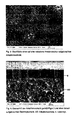
- FIG. 1 shows the surface of a reduced anode structure (Ni / 8YSZ), which is applied to a porous metallic substrate (ITM), not shown here.
- ITM porous metallic substrate
- FIG. 2 shows a transverse section of the electrolyte-coated anode structure according to FIG. 1 .
- the multilayer electrolyte was applied to the anode structure by PVD coating and consists of a CGO layer (E1), an 8YSZ layer (E2) and another CGO layer (E3).
- E1 CGO layer
- E2 8YSZ layer
- E3 CGO layer
- Clearly visible is the columnar layer growth of the electrolyte with a diversified, irregular growth.
- FIG. 3 shows the surface structure of the applied to an anode structure adaptation layer.
- FIG. 4 shows a cross-section of the adaptation layer according to FIG. 3 and an electrolyte applied thereto.
- the electrolyte is formed as a single layer of CGO and was applied by PVD.
- the growth of the electrolyte layer is undisturbed and homogeneous, so that the required gas tightness of the electrolyte is achieved.
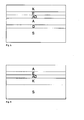
- FIGS. 5 and 6 schematically removable.
- a gas-tight thin-layer electrolyte makes certain demands on the underlying layer structure with regard to roughness and / or pore size, which can be fulfilled by an adaptation layer. If powder-metallurgical porous substrates (eg with a particle size of ⁇ 125 ⁇ m) are coated with an anode structure, then the latter can have an average pore size of up to 1.5 ⁇ m (see FIG. 1 ).
- the roughness of the surface of this anode structure should be for the square average roughness R q of less than 3 microns, preferably less than 2 microns, for the square Mikromittenrauheitswert R ⁇ q is less than 1 micron, preferably less than 0.6 microns, and the mean surface roughness R z is less than 10 microns, preferably less than 6 microns, and for the mean ⁇ Mikrorauianae R z is less than 4 microns, preferably less than 2 microns, respectively.
- the laser topograph CT200 (Cybertechnolgies GmbH, Ingolstadt) was used with a confocal laser sensor LT9010 (spot size about 2 ⁇ m, vertical resolution 10 nm).
- the primary profiles, measured in 1 ⁇ m increments, were filtered with a Gaussian filter, ⁇ In (2), 5 ⁇ m filter length prior to application of DIN regulations, to minimize single misfire due to multiple reflections.
- an 8YSZ powder having a mean dispersible primary particle size of 150 nm and a specific surface area of 13 m 2 / g was used (TZ-8Y, Tosoh Corp., Japan).
- a dipping suspension was mixed with grinding balls of diameter 5 and 10 mm and homogenized on a roller bench for 48 hours, consisting of 67.2% by weight of solvent DBE (dibasic esters, Lemro Chemie effort Michael Mrozyk KG, Grevenbroich), 30.5% by weight.
- % 8YSZ powder (TZ-8Y) and 2.3% by weight of ethylcellulose as binder (Fluka, 3-5.5 mPa s, Sigma-Aldrich Chemie GmbH, Kunststoff).
- the support substrates with the anode structure attached thereto were immersed vertically in the suspension and sintered after a drying step in H 2 atmosphere at 1200 ° C for 3 hours.
- an adaptation layer thickness of 10 to 20 ⁇ m resulted.
- the adaptation layer applied in this way exhibited a square mean roughness Rq of 1.2 ⁇ m and a mean roughness R z of 5.8 ⁇ m.
- the square micrometer roughness value R ⁇ q showed a value of 0.21 ⁇ m and the average micro-roughness R ⁇ z showed a value of 0.67 ⁇ m.
- a significant reduction in the average pore size at the surface of the adaptation layer was shown.
- the mean pore size of the adaptation layer in this case was about 240 nm (see FIG. 3 ).
- a dense electrolyte layer of Gd 2 O 3 -doped CeO 2 (CGO) could be applied by gas phase deposition (electron beam evaporation at 870 ° C., EB-PVD) with a layer thickness of approximately 1.7 ⁇ m.
- the gas tightness of this electrolyte was determined by He-leak test to 3.4 x 10 -3 (hPa dm 3 ) / (s cm 2 ) for a pressure difference of 1000 hPa. This value corresponds to common anode-supported fuel cells in the reduced state.
Priority Applications (7)
| Application Number | Priority Date | Filing Date | Title |
|---|---|---|---|
| EP09014400A EP2325931A1 (fr) | 2009-11-18 | 2009-11-18 | Agencement pour une cellule combustible ainsi que son procédé de fabrication |
| TW099138966A TW201131875A (en) | 2009-11-18 | 2010-11-12 | Assembly for a fuel cell and method for the production thereof |
| JP2012539224A JP5809159B2 (ja) | 2009-11-18 | 2010-11-17 | 燃料電池用のアッセンブリー及びそれの製造法 |
| CA2781129A CA2781129A1 (fr) | 2009-11-18 | 2010-11-17 | Systeme pour une pile a combustible ainsi que son procede de fabrication |
| EP10784263.5A EP2502296B1 (fr) | 2009-11-18 | 2010-11-17 | Agencement pour une cellula à combustible ainsi que son procédé de fabrication |
| PCT/EP2010/007002 WO2011060928A1 (fr) | 2009-11-18 | 2010-11-17 | Système pour une pile à combustible ainsi que son procédé de fabrication |
| US13/510,080 US20130189606A1 (en) | 2009-11-18 | 2010-11-17 | Assembly for a fuel cell and method for the production thereof |
Applications Claiming Priority (1)
| Application Number | Priority Date | Filing Date | Title |
|---|---|---|---|
| EP09014400A EP2325931A1 (fr) | 2009-11-18 | 2009-11-18 | Agencement pour une cellule combustible ainsi que son procédé de fabrication |
Publications (1)
| Publication Number | Publication Date |
|---|---|
| EP2325931A1 true EP2325931A1 (fr) | 2011-05-25 |
Family
ID=42077208
Family Applications (2)
| Application Number | Title | Priority Date | Filing Date |
|---|---|---|---|
| EP09014400A Withdrawn EP2325931A1 (fr) | 2009-11-18 | 2009-11-18 | Agencement pour une cellule combustible ainsi que son procédé de fabrication |
| EP10784263.5A Active EP2502296B1 (fr) | 2009-11-18 | 2010-11-17 | Agencement pour une cellula à combustible ainsi que son procédé de fabrication |
Family Applications After (1)
| Application Number | Title | Priority Date | Filing Date |
|---|---|---|---|
| EP10784263.5A Active EP2502296B1 (fr) | 2009-11-18 | 2010-11-17 | Agencement pour une cellula à combustible ainsi que son procédé de fabrication |
Country Status (6)
| Country | Link |
|---|---|
| US (1) | US20130189606A1 (fr) |
| EP (2) | EP2325931A1 (fr) |
| JP (1) | JP5809159B2 (fr) |
| CA (1) | CA2781129A1 (fr) |
| TW (1) | TW201131875A (fr) |
| WO (1) | WO2011060928A1 (fr) |
Cited By (1)
| Publication number | Priority date | Publication date | Assignee | Title |
|---|---|---|---|---|
| WO2017093310A1 (fr) * | 2015-11-30 | 2017-06-08 | Robert Bosch Gmbh | Ensemble électrode à membrane et son procédé de production, pile à combustible, sonde de gaz d'échappement et élément électrochimique |
Families Citing this family (5)
| Publication number | Priority date | Publication date | Assignee | Title |
|---|---|---|---|---|
| WO2012068239A1 (fr) * | 2010-11-17 | 2012-05-24 | Zimmer, Inc. | Implants monoblocs en céramique à surfaces de fixation ostéo-intégrées |
| DE102011083541A1 (de) | 2011-09-27 | 2013-03-28 | Siemens Aktiengesellschaft | Speicherelement |
| DE102013008472A1 (de) * | 2013-05-21 | 2014-11-27 | Plansee Composite Materials Gmbh | Mehrlagige Schichtanordnung für einen Festkörperelektrolyt |
| JP6910170B2 (ja) * | 2017-03-22 | 2021-07-28 | 大阪瓦斯株式会社 | 金属支持型電気化学素子用の電極層付基板、電気化学素子、電気化学モジュール、電気化学装置、エネルギーシステム、固体酸化物形燃料電池、および製造方法 |
| JP6910171B2 (ja) * | 2017-03-22 | 2021-07-28 | 大阪瓦斯株式会社 | 電気化学素子の製造方法および電気化学素子 |
Citations (4)
| Publication number | Priority date | Publication date | Assignee | Title |
|---|---|---|---|---|
| DE19626342A1 (de) * | 1996-07-01 | 1998-01-08 | Forschungszentrum Juelich Gmbh | Elektrodenzwischenschicht bei Brennstoffzellen |
| DE19819453A1 (de) * | 1998-04-30 | 1999-11-11 | Forschungszentrum Juelich Gmbh | SOFC-Brennstoffzelle mit einer Anodenzwischenschicht |
| DE10343652A1 (de) | 2003-09-20 | 2005-05-04 | Elringklinger Ag | Verfahren zum Herstellen einer Lötverbindung zwischen einem Substrat und einem Kontaktelement einer Brennstoffzelleneinheit |
| DE102007015358A1 (de) | 2007-03-30 | 2008-10-02 | Forschungszentrum Jülich GmbH | Schichtsystem für einen Elektrolyten einer Hochtemperatur-Brennstoffzelle sowie Verfahren zur Herstellung desselben |
Family Cites Families (12)
| Publication number | Priority date | Publication date | Assignee | Title |
|---|---|---|---|---|
| US7067208B2 (en) * | 2002-02-20 | 2006-06-27 | Ion America Corporation | Load matched power generation system including a solid oxide fuel cell and a heat pump and an optional turbine |
| DE10309968A1 (de) * | 2003-03-07 | 2004-09-23 | Forschungszentrum Jülich GmbH | Verfahren zur Herstellung eines Schichtsystems umfassend einen metallischen Träger und eine Anodenfunktionsschicht |
| JP5260052B2 (ja) * | 2004-06-10 | 2013-08-14 | テクニカル ユニバーシティ オブ デンマーク | 固体酸化物型燃料電池 |
| JP2008519404A (ja) * | 2004-10-29 | 2008-06-05 | フランクリン・フュエル・セルズ・インコーポレーテッド | 電気化学的電池構造体および制御粉末法によるその製造方法 |
| ES2292313B1 (es) * | 2005-09-27 | 2009-02-16 | Ikerlan, S. Coop. | Celda de combustible de oxido solido con soporte ferritico. |
| JP5179718B2 (ja) * | 2005-12-14 | 2013-04-10 | 日本特殊陶業株式会社 | 固体酸化物型燃料電池セル、固体酸化物型燃料電池スタック、及び固体酸化物型燃料電池セルの製造方法 |
| AT9543U1 (de) * | 2006-07-07 | 2007-11-15 | Plansee Se | Verfahren zur herstellung einer elektrisch leitfähigen schicht |
| JP4883364B2 (ja) * | 2007-03-23 | 2012-02-22 | 株式会社豊田中央研究所 | 多孔質支持体/水素選択透過膜基板及び多孔体支持型燃料電池 |
| JP5160131B2 (ja) * | 2007-04-06 | 2013-03-13 | 本田技研工業株式会社 | 電解質・電極接合体及びその製造方法 |
| WO2009005841A1 (fr) * | 2007-07-05 | 2009-01-08 | The Board Of Trustees Of The Leland Stanford Junior University | Interfaces électrode/électrolyte dans des piles à combustible à oxyde solide |
| WO2009064391A2 (fr) * | 2007-11-13 | 2009-05-22 | Bloom Energy Corporation | Pile supportée par un électrolyte conçue pour une durée de vie plus longue et pour délivrer une puissance plus élevée |
| US20110003084A1 (en) * | 2008-02-25 | 2011-01-06 | National Research Council Of Canada | Process of Making Ceria-Based Electrolyte Coating |
-
2009
- 2009-11-18 EP EP09014400A patent/EP2325931A1/fr not_active Withdrawn
-
2010
- 2010-11-12 TW TW099138966A patent/TW201131875A/zh unknown
- 2010-11-17 JP JP2012539224A patent/JP5809159B2/ja not_active Expired - Fee Related
- 2010-11-17 CA CA2781129A patent/CA2781129A1/fr not_active Abandoned
- 2010-11-17 US US13/510,080 patent/US20130189606A1/en not_active Abandoned
- 2010-11-17 WO PCT/EP2010/007002 patent/WO2011060928A1/fr active Application Filing
- 2010-11-17 EP EP10784263.5A patent/EP2502296B1/fr active Active
Patent Citations (4)
| Publication number | Priority date | Publication date | Assignee | Title |
|---|---|---|---|---|
| DE19626342A1 (de) * | 1996-07-01 | 1998-01-08 | Forschungszentrum Juelich Gmbh | Elektrodenzwischenschicht bei Brennstoffzellen |
| DE19819453A1 (de) * | 1998-04-30 | 1999-11-11 | Forschungszentrum Juelich Gmbh | SOFC-Brennstoffzelle mit einer Anodenzwischenschicht |
| DE10343652A1 (de) | 2003-09-20 | 2005-05-04 | Elringklinger Ag | Verfahren zum Herstellen einer Lötverbindung zwischen einem Substrat und einem Kontaktelement einer Brennstoffzelleneinheit |
| DE102007015358A1 (de) | 2007-03-30 | 2008-10-02 | Forschungszentrum Jülich GmbH | Schichtsystem für einen Elektrolyten einer Hochtemperatur-Brennstoffzelle sowie Verfahren zur Herstellung desselben |
Non-Patent Citations (4)
| Title |
|---|
| FONTAINE M L ET AL: "Composition and porosity graded La2-xNiO4+delta (x>=0) interlayers for SOFC: Control of the microstructure via a sol-gel process", JOURNAL OF POWER SOURCES, ELSEVIER SA, CH LNKD- DOI:10.1016/J.JPOWSOUR.2005.08.016, vol. 156, no. 1, 19 May 2006 (2006-05-19), pages 33 - 38, XP025083900, ISSN: 0378-7753, [retrieved on 20060519] * |
| LIU M ET AL: "YSZ-based SOFC with modified electrode/electrolyte interfaces for operating at temperature lower than 650<o>C", JOURNAL OF POWER SOURCES, ELSEVIER SA, CH LNKD- DOI:10.1016/J.JPOWSOUR.2008.01.066, vol. 180, no. 1, 15 May 2008 (2008-05-15), pages 215 - 220, XP022612340, ISSN: 0378-7753, [retrieved on 20080207] * |
| M.I. MENDELSON: "Average Grain Size in Polycrystalline Ceramics", J. AM. CERAM. SOC., vol. 52, no. 8, 1969, pages 443 - 446 |
| T.S. SMITH: "ASTM STP953", 1987, AMERICAN SOCIETY FOR TESTING AND MATERIALS, article "Morphological Characterization of Porous Coatings." In: "Quantitative Characterization and Performance of Porous Implants for Hard Tissue Applications", pages: 92 - 102 |
Cited By (1)
| Publication number | Priority date | Publication date | Assignee | Title |
|---|---|---|---|---|
| WO2017093310A1 (fr) * | 2015-11-30 | 2017-06-08 | Robert Bosch Gmbh | Ensemble électrode à membrane et son procédé de production, pile à combustible, sonde de gaz d'échappement et élément électrochimique |
Also Published As
| Publication number | Publication date |
|---|---|
| EP2502296A1 (fr) | 2012-09-26 |
| TW201131875A (en) | 2011-09-16 |
| EP2502296B1 (fr) | 2020-02-12 |
| CA2781129A1 (fr) | 2011-05-26 |
| JP5809159B2 (ja) | 2015-11-10 |
| WO2011060928A1 (fr) | 2011-05-26 |
| WO2011060928A8 (fr) | 2012-10-11 |
| US20130189606A1 (en) | 2013-07-25 |
| JP2013511799A (ja) | 2013-04-04 |
Similar Documents
| Publication | Publication Date | Title |
|---|---|---|
| EP2502297B1 (fr) | Anode pour une cellule combustible haute température ainsi que son utilisation | |
| EP2676318B1 (fr) | Structure à empilement et son utilisation pour former une structure à empilement en ceramique entre un interconnecteur et une cathode d'une pile a combustible haute temperature | |
| EP2036152B1 (fr) | Matériau composite céramique destiné à une anode d'une pile à combustible haute température | |
| DE19547700C2 (de) | Elektrodensubstrat für eine Brennstoffzelle | |
| EP2502296B1 (fr) | Agencement pour une cellula à combustible ainsi que son procédé de fabrication | |
| EP0788175A1 (fr) | Pile à combustible fonctionnant à haute température avec électrolyte à couche mince | |
| DE102005015755A1 (de) | Verfahren zur Herstellung einer Chromverdampfungsschutzschicht für chromoxidbildende Metallsubstrate | |
| EP2654115B1 (fr) | Procédé de fabrication d'un substrat de support, substrat de support et dispositif électrochimique | |
| EP3000149B1 (fr) | Ensemble multicouche pour électrolyte solide | |
| EP2669984B1 (fr) | Système de couches d'anode pour applications electrochimiques et son procédé de fabrication | |
| EP2156499B1 (fr) | Procédé de réalisation d'une couche d'électrolyte solide étanche aux gaz et couche d'électrolyte solide correspondante | |
| DE102006056251B4 (de) | Hochtemperaturbrennstoffzelle mit ferritischer Komponente und Verfahren zum Betreiben derselben | |
| WO2008119321A1 (fr) | Système de couches destiné à un électrolyte d'une pile à combustible haute température, et son procédé de réalisation | |
| WO2013045230A1 (fr) | Procédé de fabrication d'une pile à combustible à électrolyte solide | |
| WO2010037681A1 (fr) | Pile à combustible plane à haute température | |
| JP6837122B2 (ja) | 電気化学セル | |
| EP3697944B1 (fr) | Électrode à gaz combustible ainsi que procédé de fabrication d'une électrode à gaz combustible | |
| DE102005059708A1 (de) | Reoxidationsstabile Hochtemperatur-Brennstoffzelle | |
| DE102010028893A1 (de) | Interkonnektor für einen Brennstoffzellenstapel und Verfahren zur Herstellung |
Legal Events
| Date | Code | Title | Description |
|---|---|---|---|
| PUAI | Public reference made under article 153(3) epc to a published international application that has entered the european phase |
Free format text: ORIGINAL CODE: 0009012 |
|
| 17P | Request for examination filed |
Effective date: 20100607 |
|
| AK | Designated contracting states |
Kind code of ref document: A1 Designated state(s): AT BE BG CH CY CZ DE DK EE ES FI FR GB GR HR HU IE IS IT LI LT LU LV MC MK MT NL NO PL PT RO SE SI SK SM TR |
|
| AX | Request for extension of the european patent |
Extension state: AL BA RS |
|
| STAA | Information on the status of an ep patent application or granted ep patent |
Free format text: STATUS: THE APPLICATION IS DEEMED TO BE WITHDRAWN |
|
| 18D | Application deemed to be withdrawn |
Effective date: 20111126 |