EP2325906B1 - Lichtemittierendes Halbleiterbauelement und Herstellungsverfahren - Google Patents
Lichtemittierendes Halbleiterbauelement und Herstellungsverfahren Download PDFInfo
- Publication number
- EP2325906B1 EP2325906B1 EP10157158.6A EP10157158A EP2325906B1 EP 2325906 B1 EP2325906 B1 EP 2325906B1 EP 10157158 A EP10157158 A EP 10157158A EP 2325906 B1 EP2325906 B1 EP 2325906B1
- Authority
- EP
- European Patent Office
- Prior art keywords
- semiconductor layer
- layer
- major surface
- phosphor
- semiconductor
- Prior art date
- Legal status (The legal status is an assumption and is not a legal conclusion. Google has not performed a legal analysis and makes no representation as to the accuracy of the status listed.)
- Active
Links
- 239000004065 semiconductor Substances 0.000 title claims description 164
- 238000000034 method Methods 0.000 title claims description 17
- 238000004519 manufacturing process Methods 0.000 title claims description 8
- OAICVXFJPJFONN-UHFFFAOYSA-N Phosphorus Chemical compound [P] OAICVXFJPJFONN-UHFFFAOYSA-N 0.000 claims description 59
- 239000002184 metal Substances 0.000 claims description 39
- 229910052751 metal Inorganic materials 0.000 claims description 39
- 239000000758 substrate Substances 0.000 claims description 24
- 229920005989 resin Polymers 0.000 claims description 20
- 239000011347 resin Substances 0.000 claims description 20
- 239000007788 liquid Substances 0.000 claims description 2
- 239000002245 particle Substances 0.000 claims description 2
- 239000004020 conductor Substances 0.000 claims 1
- 238000000576 coating method Methods 0.000 description 6
- 239000011248 coating agent Substances 0.000 description 5
- 238000007747 plating Methods 0.000 description 5
- 239000000463 material Substances 0.000 description 4
- VYPSYNLAJGMNEJ-UHFFFAOYSA-N Silicium dioxide Chemical compound O=[Si]=O VYPSYNLAJGMNEJ-UHFFFAOYSA-N 0.000 description 3
- 238000009713 electroplating Methods 0.000 description 3
- 229910052814 silicon oxide Inorganic materials 0.000 description 3
- RYGMFSIKBFXOCR-UHFFFAOYSA-N Copper Chemical compound [Cu] RYGMFSIKBFXOCR-UHFFFAOYSA-N 0.000 description 2
- PXHVJJICTQNCMI-UHFFFAOYSA-N Nickel Chemical compound [Ni] PXHVJJICTQNCMI-UHFFFAOYSA-N 0.000 description 2
- 238000005253 cladding Methods 0.000 description 2
- 229910052802 copper Inorganic materials 0.000 description 2
- 239000010949 copper Substances 0.000 description 2
- 229910003460 diamond Inorganic materials 0.000 description 2
- 239000010432 diamond Substances 0.000 description 2
- 150000004767 nitrides Chemical class 0.000 description 2
- 230000003287 optical effect Effects 0.000 description 2
- 238000001020 plasma etching Methods 0.000 description 2
- 230000008569 process Effects 0.000 description 2
- 229910000679 solder Inorganic materials 0.000 description 2
- IJGRMHOSHXDMSA-UHFFFAOYSA-N Atomic nitrogen Chemical compound N#N IJGRMHOSHXDMSA-UHFFFAOYSA-N 0.000 description 1
- BQCADISMDOOEFD-UHFFFAOYSA-N Silver Chemical compound [Ag] BQCADISMDOOEFD-UHFFFAOYSA-N 0.000 description 1
- 238000010521 absorption reaction Methods 0.000 description 1
- 230000015572 biosynthetic process Effects 0.000 description 1
- 230000000052 comparative effect Effects 0.000 description 1
- 150000001875 compounds Chemical class 0.000 description 1
- 239000013078 crystal Substances 0.000 description 1
- 238000005520 cutting process Methods 0.000 description 1
- 238000000354 decomposition reaction Methods 0.000 description 1
- 229910001873 dinitrogen Inorganic materials 0.000 description 1
- 239000003822 epoxy resin Substances 0.000 description 1
- 238000000605 extraction Methods 0.000 description 1
- PCHJSUWPFVWCPO-UHFFFAOYSA-N gold Chemical compound [Au] PCHJSUWPFVWCPO-UHFFFAOYSA-N 0.000 description 1
- 229910052737 gold Inorganic materials 0.000 description 1
- 239000010931 gold Substances 0.000 description 1
- 238000013007 heat curing Methods 0.000 description 1
- 230000005012 migration Effects 0.000 description 1
- 238000013508 migration Methods 0.000 description 1
- 229910052759 nickel Inorganic materials 0.000 description 1
- 229920000647 polyepoxide Polymers 0.000 description 1
- -1 polymide Chemical compound 0.000 description 1
- 230000009467 reduction Effects 0.000 description 1
- 229910052594 sapphire Inorganic materials 0.000 description 1
- 239000010980 sapphire Substances 0.000 description 1
- 238000007789 sealing Methods 0.000 description 1
- 229920002050 silicone resin Polymers 0.000 description 1
- 229910052709 silver Inorganic materials 0.000 description 1
- 239000004332 silver Substances 0.000 description 1
- 238000004528 spin coating Methods 0.000 description 1
- 230000008719 thickening Effects 0.000 description 1
- XLYOFNOQVPJJNP-UHFFFAOYSA-N water Substances O XLYOFNOQVPJJNP-UHFFFAOYSA-N 0.000 description 1
Images


Classifications
-
- H—ELECTRICITY
- H01—ELECTRIC ELEMENTS
- H01L—SEMICONDUCTOR DEVICES NOT COVERED BY CLASS H10
- H01L33/00—Semiconductor devices having potential barriers specially adapted for light emission; Processes or apparatus specially adapted for the manufacture or treatment thereof or of parts thereof; Details thereof
- H01L33/48—Semiconductor devices having potential barriers specially adapted for light emission; Processes or apparatus specially adapted for the manufacture or treatment thereof or of parts thereof; Details thereof characterised by the semiconductor body packages
- H01L33/50—Wavelength conversion elements
- H01L33/507—Wavelength conversion elements the elements being in intimate contact with parts other than the semiconductor body or integrated with parts other than the semiconductor body
-
- H—ELECTRICITY
- H01—ELECTRIC ELEMENTS
- H01L—SEMICONDUCTOR DEVICES NOT COVERED BY CLASS H10
- H01L24/00—Arrangements for connecting or disconnecting semiconductor or solid-state bodies; Methods or apparatus related thereto
- H01L24/01—Means for bonding being attached to, or being formed on, the surface to be connected, e.g. chip-to-package, die-attach, "first-level" interconnects; Manufacturing methods related thereto
- H01L24/10—Bump connectors ; Manufacturing methods related thereto
-
- H—ELECTRICITY
- H01—ELECTRIC ELEMENTS
- H01L—SEMICONDUCTOR DEVICES NOT COVERED BY CLASS H10
- H01L24/00—Arrangements for connecting or disconnecting semiconductor or solid-state bodies; Methods or apparatus related thereto
- H01L24/93—Batch processes
- H01L24/94—Batch processes at wafer-level, i.e. with connecting carried out on a wafer comprising a plurality of undiced individual devices
-
- H—ELECTRICITY
- H01—ELECTRIC ELEMENTS
- H01L—SEMICONDUCTOR DEVICES NOT COVERED BY CLASS H10
- H01L24/00—Arrangements for connecting or disconnecting semiconductor or solid-state bodies; Methods or apparatus related thereto
- H01L24/93—Batch processes
- H01L24/95—Batch processes at chip-level, i.e. with connecting carried out on a plurality of singulated devices, i.e. on diced chips
- H01L24/96—Batch processes at chip-level, i.e. with connecting carried out on a plurality of singulated devices, i.e. on diced chips the devices being encapsulated in a common layer, e.g. neo-wafer or pseudo-wafer, said common layer being separable into individual assemblies after connecting
-
- H—ELECTRICITY
- H01—ELECTRIC ELEMENTS
- H01L—SEMICONDUCTOR DEVICES NOT COVERED BY CLASS H10
- H01L24/00—Arrangements for connecting or disconnecting semiconductor or solid-state bodies; Methods or apparatus related thereto
- H01L24/93—Batch processes
- H01L24/95—Batch processes at chip-level, i.e. with connecting carried out on a plurality of singulated devices, i.e. on diced chips
- H01L24/97—Batch processes at chip-level, i.e. with connecting carried out on a plurality of singulated devices, i.e. on diced chips the devices being connected to a common substrate, e.g. interposer, said common substrate being separable into individual assemblies after connecting
-
- H—ELECTRICITY
- H01—ELECTRIC ELEMENTS
- H01L—SEMICONDUCTOR DEVICES NOT COVERED BY CLASS H10
- H01L33/00—Semiconductor devices having potential barriers specially adapted for light emission; Processes or apparatus specially adapted for the manufacture or treatment thereof or of parts thereof; Details thereof
- H01L33/36—Semiconductor devices having potential barriers specially adapted for light emission; Processes or apparatus specially adapted for the manufacture or treatment thereof or of parts thereof; Details thereof characterised by the electrodes
- H01L33/38—Semiconductor devices having potential barriers specially adapted for light emission; Processes or apparatus specially adapted for the manufacture or treatment thereof or of parts thereof; Details thereof characterised by the electrodes with a particular shape
- H01L33/382—Semiconductor devices having potential barriers specially adapted for light emission; Processes or apparatus specially adapted for the manufacture or treatment thereof or of parts thereof; Details thereof characterised by the electrodes with a particular shape the electrode extending partially in or entirely through the semiconductor body
-
- H—ELECTRICITY
- H01—ELECTRIC ELEMENTS
- H01L—SEMICONDUCTOR DEVICES NOT COVERED BY CLASS H10
- H01L33/00—Semiconductor devices having potential barriers specially adapted for light emission; Processes or apparatus specially adapted for the manufacture or treatment thereof or of parts thereof; Details thereof
- H01L33/36—Semiconductor devices having potential barriers specially adapted for light emission; Processes or apparatus specially adapted for the manufacture or treatment thereof or of parts thereof; Details thereof characterised by the electrodes
- H01L33/38—Semiconductor devices having potential barriers specially adapted for light emission; Processes or apparatus specially adapted for the manufacture or treatment thereof or of parts thereof; Details thereof characterised by the electrodes with a particular shape
- H01L33/385—Semiconductor devices having potential barriers specially adapted for light emission; Processes or apparatus specially adapted for the manufacture or treatment thereof or of parts thereof; Details thereof characterised by the electrodes with a particular shape the electrode extending at least partially onto a side surface of the semiconductor body
-
- H—ELECTRICITY
- H01—ELECTRIC ELEMENTS
- H01L—SEMICONDUCTOR DEVICES NOT COVERED BY CLASS H10
- H01L33/00—Semiconductor devices having potential barriers specially adapted for light emission; Processes or apparatus specially adapted for the manufacture or treatment thereof or of parts thereof; Details thereof
- H01L33/36—Semiconductor devices having potential barriers specially adapted for light emission; Processes or apparatus specially adapted for the manufacture or treatment thereof or of parts thereof; Details thereof characterised by the electrodes
- H01L33/38—Semiconductor devices having potential barriers specially adapted for light emission; Processes or apparatus specially adapted for the manufacture or treatment thereof or of parts thereof; Details thereof characterised by the electrodes with a particular shape
- H01L33/387—Semiconductor devices having potential barriers specially adapted for light emission; Processes or apparatus specially adapted for the manufacture or treatment thereof or of parts thereof; Details thereof characterised by the electrodes with a particular shape with a plurality of electrode regions in direct contact with the semiconductor body and being electrically interconnected by another electrode layer
-
- H—ELECTRICITY
- H01—ELECTRIC ELEMENTS
- H01L—SEMICONDUCTOR DEVICES NOT COVERED BY CLASS H10
- H01L33/00—Semiconductor devices having potential barriers specially adapted for light emission; Processes or apparatus specially adapted for the manufacture or treatment thereof or of parts thereof; Details thereof
- H01L33/48—Semiconductor devices having potential barriers specially adapted for light emission; Processes or apparatus specially adapted for the manufacture or treatment thereof or of parts thereof; Details thereof characterised by the semiconductor body packages
- H01L33/50—Wavelength conversion elements
-
- H—ELECTRICITY
- H01—ELECTRIC ELEMENTS
- H01L—SEMICONDUCTOR DEVICES NOT COVERED BY CLASS H10
- H01L2224/00—Indexing scheme for arrangements for connecting or disconnecting semiconductor or solid-state bodies and methods related thereto as covered by H01L24/00
- H01L2224/01—Means for bonding being attached to, or being formed on, the surface to be connected, e.g. chip-to-package, die-attach, "first-level" interconnects; Manufacturing methods related thereto
- H01L2224/10—Bump connectors; Manufacturing methods related thereto
- H01L2224/15—Structure, shape, material or disposition of the bump connectors after the connecting process
- H01L2224/16—Structure, shape, material or disposition of the bump connectors after the connecting process of an individual bump connector
-
- H—ELECTRICITY
- H01—ELECTRIC ELEMENTS
- H01L—SEMICONDUCTOR DEVICES NOT COVERED BY CLASS H10
- H01L2924/00—Indexing scheme for arrangements or methods for connecting or disconnecting semiconductor or solid-state bodies as covered by H01L24/00
- H01L2924/10—Details of semiconductor or other solid state devices to be connected
- H01L2924/11—Device type
- H01L2924/12—Passive devices, e.g. 2 terminal devices
- H01L2924/1204—Optical Diode
- H01L2924/12041—LED
-
- H—ELECTRICITY
- H01—ELECTRIC ELEMENTS
- H01L—SEMICONDUCTOR DEVICES NOT COVERED BY CLASS H10
- H01L2924/00—Indexing scheme for arrangements or methods for connecting or disconnecting semiconductor or solid-state bodies as covered by H01L24/00
- H01L2924/10—Details of semiconductor or other solid state devices to be connected
- H01L2924/11—Device type
- H01L2924/12—Passive devices, e.g. 2 terminal devices
- H01L2924/1204—Optical Diode
- H01L2924/12042—LASER
-
- H—ELECTRICITY
- H01—ELECTRIC ELEMENTS
- H01L—SEMICONDUCTOR DEVICES NOT COVERED BY CLASS H10
- H01L2933/00—Details relating to devices covered by the group H01L33/00 but not provided for in its subgroups
- H01L2933/0008—Processes
- H01L2933/0033—Processes relating to semiconductor body packages
- H01L2933/0041—Processes relating to semiconductor body packages relating to wavelength conversion elements
-
- H—ELECTRICITY
- H01—ELECTRIC ELEMENTS
- H01L—SEMICONDUCTOR DEVICES NOT COVERED BY CLASS H10
- H01L33/00—Semiconductor devices having potential barriers specially adapted for light emission; Processes or apparatus specially adapted for the manufacture or treatment thereof or of parts thereof; Details thereof
- H01L33/005—Processes
- H01L33/0093—Wafer bonding; Removal of the growth substrate
-
- H—ELECTRICITY
- H01—ELECTRIC ELEMENTS
- H01L—SEMICONDUCTOR DEVICES NOT COVERED BY CLASS H10
- H01L33/00—Semiconductor devices having potential barriers specially adapted for light emission; Processes or apparatus specially adapted for the manufacture or treatment thereof or of parts thereof; Details thereof
- H01L33/005—Processes
- H01L33/0095—Post-treatment of devices, e.g. annealing, recrystallisation or short-circuit elimination
-
- H—ELECTRICITY
- H01—ELECTRIC ELEMENTS
- H01L—SEMICONDUCTOR DEVICES NOT COVERED BY CLASS H10
- H01L33/00—Semiconductor devices having potential barriers specially adapted for light emission; Processes or apparatus specially adapted for the manufacture or treatment thereof or of parts thereof; Details thereof
- H01L33/02—Semiconductor devices having potential barriers specially adapted for light emission; Processes or apparatus specially adapted for the manufacture or treatment thereof or of parts thereof; Details thereof characterised by the semiconductor bodies
- H01L33/20—Semiconductor devices having potential barriers specially adapted for light emission; Processes or apparatus specially adapted for the manufacture or treatment thereof or of parts thereof; Details thereof characterised by the semiconductor bodies with a particular shape, e.g. curved or truncated substrate
-
- H—ELECTRICITY
- H01—ELECTRIC ELEMENTS
- H01L—SEMICONDUCTOR DEVICES NOT COVERED BY CLASS H10
- H01L33/00—Semiconductor devices having potential barriers specially adapted for light emission; Processes or apparatus specially adapted for the manufacture or treatment thereof or of parts thereof; Details thereof
- H01L33/44—Semiconductor devices having potential barriers specially adapted for light emission; Processes or apparatus specially adapted for the manufacture or treatment thereof or of parts thereof; Details thereof characterised by the coatings, e.g. passivation layer or anti-reflective coating
-
- H—ELECTRICITY
- H01—ELECTRIC ELEMENTS
- H01L—SEMICONDUCTOR DEVICES NOT COVERED BY CLASS H10
- H01L33/00—Semiconductor devices having potential barriers specially adapted for light emission; Processes or apparatus specially adapted for the manufacture or treatment thereof or of parts thereof; Details thereof
- H01L33/48—Semiconductor devices having potential barriers specially adapted for light emission; Processes or apparatus specially adapted for the manufacture or treatment thereof or of parts thereof; Details thereof characterised by the semiconductor body packages
- H01L33/483—Containers
- H01L33/486—Containers adapted for surface mounting
-
- H—ELECTRICITY
- H01—ELECTRIC ELEMENTS
- H01L—SEMICONDUCTOR DEVICES NOT COVERED BY CLASS H10
- H01L33/00—Semiconductor devices having potential barriers specially adapted for light emission; Processes or apparatus specially adapted for the manufacture or treatment thereof or of parts thereof; Details thereof
- H01L33/48—Semiconductor devices having potential barriers specially adapted for light emission; Processes or apparatus specially adapted for the manufacture or treatment thereof or of parts thereof; Details thereof characterised by the semiconductor body packages
- H01L33/62—Arrangements for conducting electric current to or from the semiconductor body, e.g. lead-frames, wire-bonds or solder balls
Definitions
- a wavelength-converting light-emitting diode is conventionally known, in which a blue light-emitting element is combined with a phosphor layer to produce white light.
- JP-A-2005-116998 discloses a manufacturing technique in which a phosphor layer is formed on the upper surface of a wafer including numerous LEDs, and then the wafer is cut into chip-size pieces. Thus, in this technique, the phosphor layer is formed only on the upper surface of the light-emitting diode.
- US 2004/0188696 A1 describes a process, in which an optical coating can be applied to LED dice flip chip bonded to a sub-mount wafer.
- the optical coating can be applied to the frontside of the sub-mount wafer including the LED dice, in which case the coating also coats the sub-mount wafer.
- US 6,331,450 B1 describes a flip-chip-type device that is formed from a plurality of flip-chip semiconductor device units integrated together on a common substrate.
- a curable sealing resin is laminated on a surface of the common substrate on which electrodes are formed and cured.
- US 2009/0014736 A1 relates to methods for fabricating semiconductor devices coated with coating material.
- the wire bond pads are placed on the side of the devices on which the coating is applied and the document thus aims at solving the challenge of accessing the wire bond pad on the device after the coating process.
- EP 1 198 016 A2 involves a method for forming a luminescent layer on a light emitting semiconductor device by use of stencilling.
- the resulting light emitting device is described as including a stack of layers including semiconductor layers comprising an active region and a luminescent material containing layer having a substantially uniform thickness disposed around at least a portion of the stack.
- EP 1 020 935 A2 describes a process of fabricating a semiconductor light-emitting unit in which LED's are placed over diodes on a wafer such that the circuitry side of each of the LED's faces the principal surface of the wafer.
- the document further describes that the principal surface of the wafer is coated with a wave-length-shifting resin medium 3 containing a photofluorescent compound to cover the LED's.
- US 2007/262338 A1 relates to a semiconductor light-emitting element, a manufacturing method and a mounting method of the same and a light-emitting device formed by mounting such semiconductor light-emitting element on a circuit board.
- An LED chip has a structure in which an n-type semiconductor layer and a p-type semiconductor layer are successively formed on the lower face of an element substrate, with the p-type semiconductor layer being formed on an area except for an area for an n-electrode.
- a first n-electrode is formed on the area for the n-electrode and a first p-electrode is formed on the p-type semiconductor layer.
- a first insulating layer having openings is formed on the first n-electrode and the first p-electrode, and a second n-electrode and a second p-electrode having virtually the same size are formed on the first insulating layer.
- a semiconductor light-emitting device as defined by claim 1.
- FIG. 1A is a schematic cross-sectional view of a semiconductor light-emitting device according to an embodiment.
- the semiconductor light-emitting device includes a semiconductor structure section, a package structure section including an interconnect layer, and a phosphor layer, which are collectively formed in a wafer state.
- the semiconductor structure section includes a first semiconductor layer 12 and a second semiconductor layer 13.
- the second semiconductor layer 13 has a structure in which a light-emitting layer (or active layer) is sandwiched between a p-type cladding layer and an n-type cladding layer.
- the first semiconductor layer 12 is illustratively of n-type and functions as a lateral current path.
- the conductivity type of the first semiconductor layer 12 is not limited to n-type, but may be p-type.
- the first major surface of the first semiconductor layer 12 is a top surface 10, and light is extracted outside mainly from the top surface 10.
- the second semiconductor layer 13 is provided on the second major surface opposite to the top surface 10. Part of the second major surface side of the first semiconductor layer 12 is processed into a protruding shape, and the second semiconductor layer 13 is provided on the surface of that protrusion.
- the second semiconductor layer 13 is smaller in planar size than the first semiconductor layer 12.
- An n-side electrode 15 is provided on the portion of the second major surface of the first semiconductor layer 12 where the second semiconductor layer 13 is not provided.
- a p-side electrode 16 is provided on the surface of the second semiconductor layer 13 opposite to its surface in contact with the first semiconductor layer 12.
- the portion of the second major surface and the second semiconductor layer 13 other than the portion where the n-side electrode 15 and the p-side electrode 16 are provided is covered with an insulating film 14. Furthermore, an insulating layer 17 is provided on the second major surface side of the first semiconductor layer 12 so as to cover the insulating film 14, the n-side electrode 15, and the p-side electrode 16.
- the insulating film 14 is made of silicon oxide
- the insulating layer 17 is made of silicon oxide or a resin such as polymide
- the n-side electrode 15 and the p-side electrode 16 are insulated from each other by the insulating film 14 and the insulating layer 17 and serve as electrically independent electrodes.
- the insulating layer 17 has a first surface 17a which is located on the side of the second major surface of the first semiconductor layer 12, the n-side electrode 15, and the p-side electrode 16, and a second surface 17b located on the opposite side from the first surface 17a.
- the second surface 17b is planarized, and an n-side interconnect 18 and a p-side Interconnect 19 are provided on the second surface 17b.
- the n-side interconnect 18 is provided also in an opening which is formed in the insulating layer 17 so as to reach the n-side electrode 15, and the n-side interconnect 18 is electrically connected to the n-side electrode 15.
- the p-side interconnect 19 is provided also in an opening which is formed in the insulating layer 17 so as to reach the p-side electrode 16, and the p-side interconnect 19 is electrically connected to the p-side electrode 16.
- the n-side interconnect 18 and the p-side interconnect 19 are formed by electrolytic plating in which a seed metal formed on the inner wall surface of the opening and the second surface 17b of the insulating layer 17 is used as a current path.
- n-side electrode 15, the p-side electrode 16, the n-side interconnect 18, the p-side interconnect 19, the insulating film 14, and the insulating layer 17 are all provided on the opposite side of the semiconductor structure section from the top surface 10 and constitute the interconnect layer.
- An n-side metal pillar 21 is provided below the n-side interconnect 18.
- a p-side metal pillar 22 is provided below the p-side interconnect 19.
- the second surface 17b of the insulating layer 17, the periphery of the n-side metal pillar 21, the periphery of the p-side metal pillar 22, the n-side interconnect 18, and the p-side interconnect 19 are covered with a resin 23.
- the first semiconductor layer 12 is electrically connected to the n-side metal pillar 21 through the n-side electrode 15 and the n-side interconnect 18.
- the second semiconductor layer 13 is electrically connected to the p-side metal pillar 22 through the p-side electrode 16 and the p-side interconnect 19.
- External terminals 24 such as solder balls and metal bumps are provided on the lower end surface (the end surface on the opposite side from the junction with the n-side interconnect 18 and the p-side interconnect 19) of the n-side metal pillar 21 and the p-side metal pillar 22 exposed from the resin 23, and the semiconductor light-emitting device according to this embodiment can be electrically connected to external circuits through the external terminals 24.
- the semiconductor structure section (the multilayer body of the first semiconductor layer 12 and the second semiconductor layer 13) is thin, its mechanical strength can be maintained by thickening the n-side metal pillar 21, the p-side metal pillar 22, and the resin 23.
- the n-side metal pillar 21 and the p-side metal pillar 22 can absorb and relax the stress applied to the semiconductor layer through the external terminals 24 when the device is mounted on a circuit board or the like.
- the resin 23 serving to support the n-side metal pillar 21 and the p-side metal pillar 22 has a thermal expansion coefficient which is equal or close to that of the circuit board and the like. Examples of the resin 23 include epoxy resin, silicone resin, and fluororesin.
- the n-side interconnect 18, the p-side interconnect 19, the n-side metal pillar 21, and the p-side metal pillar 22 can be made of such a material as copper, gold, nickel, and silver, Among them, it is more preferable to use copper, which has good thermal conductivity, high migration resistance, and superior contact with the insulating film.
- the first semiconductor layer 12, the second semiconductor layer 13, the insulating layer 17, the resin 23 and the like are collectively formed in a wafer state.
- a groove reaching the first surface 17a of the insulating layer 17 through the first semiconductor layer 12 is formed in the first semiconductor layer 12.
- the semiconductor light-emitting device shown in FIG. 1A is a singulated one diced at the position of the groove.
- a step portion 31 is formed between the first surface 17a of the insulating layer 17 and the top surface 10, which is the first major surface of the first semiconductor layer 12.
- the light-emitting layer is provided near an interface 50 between the first semiconductor layer 12 and the second semiconductor layer 13, and emits light by supply of current to the first semiconductor layer 12 and the second semiconductor layer 13 through the aforementioned metal pillars, interconnects, and electrodes.
- the light emitted from the light-emitting layer travels in the first semiconductor layer 12, and is emitted outside from the top surface 10 and the side surface 12a of the first semiconductor layer 12.
- the side surface 12a results from the formation of the groove in the first semiconductor layer 12.
- a phosphor layer 40 is opposed to the top surface 10 and the side surface 12a.
- the phosphor layer 40 covers the top surface 10 and the side surface 12a.
- the phosphor layer 40 covering the top surface 10 and the phosphor layer 40 covering the side surface 12a are continuously and integrally provided, and the phosphor layer 40 continuously covers the step portion 31, between the first surface 17a of the insulating layer 17 and the top surface 10.
- the phosphor layer 40 covers the top surface 10 and the side surface 12a with a generally uniform thickness.
- the phosphor layer 40 can absorb the light from the light-emitting layer and emit wavelength-converted light. Thus, it is possible to emit mixed light of the light from the light-emitting layer and the wavelength-converted light of the phosphor layer 40. For instance, for a nitride light-emitting layer, a white color, incandescent color and the like can be obtained as a mixed color of blue light from the light-emitting layer and yellow light, for instance, which is the wavelength-converted light of a yellow phosphor layer 40.
- FIG. 1B shows a planar layout of the first semiconductor layer 12, the second semiconductor layer 13, and the insulating layer 17.
- the first semiconductor layer 12 is larger in planar size than the second semiconductor layer 13, and the side surface 12a of the first semiconductor layer 12 is located outside the edge of the second semiconductor layer 13.
- the insulating layer 17 is larger in planar size than the first semiconductor layer 12, and a portion of the first surface 17a of the insulating layer 17 is located outside the side surface 12a.
- the phosphor layer 40 provided on and above that portion of the first surface 17a of the insulating layer 17 and being adjacent to the side surface 12a continuously surrounds, like a frame, the periphery of the side surface 12a of the first semiconductor layer 12,
- the first semiconductor layer 12 is covered with the phosphor layer 40 not only on the top surface 10 but also on the side surface 12a. Hence, light emitted from the side surface 12a can also pass through the phosphor layer 40. Because the phosphor layer 40 covering the top surface 10 has generally the same thickness as the phosphor layer 40 covering the side surface 12a, the distance in the phosphor layer 40 traversed by the light emitted from the top surface 10 is generally equal to the distance in the phosphor layer 40 traversed by the light emitted from the side surface 12a. This prevents variation in chromaticity, and light with a desired chromaticity can be extracted outside.
- the edge 50a of the interface 50 between the first semiconductor layer 12 and the second semiconductor layer 13 is located inside the side surface 12a.
- the distance between the edge 50a of the interface 50 and the side surface 12a is generally uniform in all directions, or throughout the circumference, in plan view. Thus, light with generally uniform brightness and chromaticity can be extracted from any side surface 12a.
- the insulating layer 17 and the resin 23 are larger in planar size than the first semiconductor layer 12, and the edge of the insulating layer 17 and the resin 23 protrude outside from the side surface 12a of the first semiconductor layer 12.
- the first semiconductor layer 12 is provided in a mesa or trapezoidal shape on the first surface 17a of the insulating layer 17.
- the phosphor layer 40 covering the side surface 12a at the step portion 31 is located on the first surface 17a of the insulating layer 17 above the external terminals 24, and does not cover the side surface of the insulating layer 17 and the resin 23. Furthermore, the phosphor layer 40 does not cover the external terminals 24, either. Thus, the phosphor layer 40 is not formed uselessly on the portion making no contribution to emission of light, which serves for cost reduction.
- the chip may be covered with a phosphor layer after flip-chip mounting.
- a phosphor layer after flip-chip mounting.
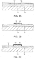
- a first semiconductor layer 12 is formed on the major surface of a substrate 11, and a second semiconductor layer 13 is formed thereon.
- the surface of the first semiconductor layer 12 in contact with the major surface of the substrate 11 which is the top surface 10.
- the first semiconductor layer 12 and the second semiconductor layer 13 can be crystal grown on a sapphire substrate.
- the first semiconductor layer 12 and the second semiconductor layer 13 are processed. As shown in FIG. 2B , part of the first semiconductor layer 12 is processed into a protruding shape, and the second semiconductor layer 13 is selectively left on the surface of that protrusion.
- an insulating film 14 entirely covering the first semiconductor layer 12 and the second semiconductor layer 13 is formed.
- the insulating film 14 is illustratively a silicon oxide film.
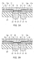
- openings are selectively formed in the insulating film 14. Then, an n-side electrode 15 is formed on the first semiconductor layer 12 exposed to the opening. Likewise, a p-side electrode 16 is formed on the second semiconductor layer 13 exposed to the opening of the insulating film 14.
- an insulating layer 17 covering the n-side electrode 15, the p-side electrode 16, and the insulating film 14 is formed. Then, as shown in FIG. 3B , an opening reaching the n-side electrode 15 and an opening reaching the p-side electrode 16 are formed in the insulating layer 17.
- a seed metal is formed on the second surface 17b and the inner wall of the opening of the insulating layer 17, and a plating resist, not shown, is further formed. Then, electrolytic plating is performed using the seed metal as a current path.
- an n-side interconnect 18 connected to the n-side electrode 15 and a p-side interconnect 19 connected to the p-side electrode 16 are formed in the openings of the insulating layer 17 and on the insulating layer 17 therearound.
- the plating resist used in the plating for forming the n-side interconnect 18 and the p-side interconnect 19 is removed.
- another plating resist for forming metal pillars is formed, and electrolytic plating is performed using the aforementioned seed metal as a current path.
- an n-side metal pillar 21 is formed on the n-side interconnect 18, and a p-side metal pillar 22 is formed on the p-side interconnect 19.
- the plating resist is removed, and furthermore the exposed portion of the seed metal is removed. This breaks the electrical connection between the n-side interconnect 18 and the p-side interconnect 19 through the seed metal.
- the n-side interconnect 18, the p-side interconnect 19, the n-side metal pillar 21, the p-side metal pillar 22, and the insulating layer 17 are covered with a resin 23. Subsequently, the surface of the resin 23 is ground to expose the upper surface of the n-side metal pillar 21 and the p-side metal pillar 22. Then, external terminals 24 such as solder balls and metal bumps are provided on the exposed surface.
- FIG. 4B is depicted with the positional relationship turned upside down with respect to FIG. 4A .
- the substrate 11 is removed from the first semiconductor layer 12 illustratively by laser lift-off. More specifically, laser light is applied toward the first semiconductor layer 12 from the rear surface side of the substrate 11, which is opposite to its major surface on which the first semiconductor layer 12 is formed. The laser light has a wavelength to which the substrate 11 is transmissive and which falls in an absorption region of the first semiconductor layer 12.
- the first semiconductor layer 12 near the interface is decomposed by absorbing the energy of the laser light.
- the first semiconductor layer 12 is made of GaN
- it is decomposed into Ga and nitrogen gas.
- Ga is left on the first semiconductor layer 12 side.
- This decomposition reaction forms a small gap between the substrate 11 and the first semiconductor layer 12, thereby separating the substrate 11 from the first semiconductor layer 12. Irradiation with the laser light is performed in a plurality of times on predefined regions across the wafer to strip the substrate 11.
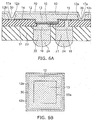
- a groove 30 is formed in the first semiconductor layer 12 as shown in FIG. 5A .
- the groove 30 reaches the first surface 17a of the insulating layer 17 through the first semiconductor layer 12 and the insulating film 14.
- the groove 30 can illustratively be formed by RIE (reactive ion etching) using a mask.
- the cross section of the groove 30 tends to be shaped like an inverted truncated cone, and hence the side surface 12a exposed into the groove 30 is formed as a sloped surface.
- the groove 30 is illustratively formed like a lattice on the wafer.
- the groove 30 may be formed using laser processing, a diamond blade and the like.
- the side surface 12a which is the inner wall surface of the groove 30, may not be a sloped surface, but a surface generally perpendicular to the top surface 10.
- a phosphor layer 40 is formed on the first semiconductor layer 12 and the inner wall of the groove 30.
- the phosphor layer 40 continuously and integrally covers the top surface 10 and the side surface 12a.
- the phosphor layer 40 is formed by applying a liquid resin mixed with phosphor particles by spin-coating, and then heat-curing it. This method has a good controllability with which the thickness of the phosphor layer 40 is kept generally uniform between the portion covering the top surface 10 and the portion covering the side surface 12a.
- the substrate 11 does not exist between the top surface 10 and the phosphor layer 40, which serves to increase the light extraction efficiency.
- the means for dicing can illustratively be machine cutting using a diamond blade or the like, laser irradiation, or high-pressure water.
- dicing can be easily performed, and the productivity can be improved.
- the aforementioned steps up to dicing are each performed collectively in the wafer state, which enables production at low cost. Furthermore, the package structure including the interconnect layer, the resin 23, and the metal pillars 21, 22 is formed in the wafer level. This facilitates downsizing in which the overall planar size of the semiconductor light-emitting device is close to the planar size of the bare chip (first semiconductor layer 12 and second semiconductor layer 13).
- FIG. 6A shows a semiconductor light-emitting device according to another embodiment which is singulated by dicing at a position outside the groove 30.
- FIG. 6B shows a planar layout of its major components.
- FIG. 8B shows a planar layout of the major components in the wafer state before dicing.
- the first semiconductor layer 12 is divided by the groove 30 into a light-emitting section and a non-light-emitting section 12b.
- the light-emitting section includes the multilayer structure (protrusion) with the second semiconductor layer 13, and the portions where the electrodes 15, 16 are formed.
- the non-light-emitting section 12b does not include the light-emitting layer, and is not connected to the electrodes 15, 16, thus not emitting light.
- the groove 30 continuously surrounds the periphery of the side surface 12a of the light-emitting section of the first semiconductor layer 12, and the non-light-emitting section 12b surrounds the groove 30.
- the phosphor layer 40 is formed on the top surface 10 and in the groove 30 in the wafer state, and subsequently the device is diced at the position of the non-light-emitting section 12b of the first semiconductor layer 12.
- the dicing line DL is shown by dashed lines.
- dicing at the position of the groove 30 can reduce ineffective area making no contribution to light emission and can decrease the planar size of the singulated device.
- the substrate 11 may not be completely removed, but ground thinly and left on the top surface 10 as shown in FIG. 7 .
- the substrate 11 may not be completely removed, but ground thinly and left on the top surface 10 as shown in FIG. 7 .
Landscapes
- Engineering & Computer Science (AREA)
- Microelectronics & Electronic Packaging (AREA)
- Computer Hardware Design (AREA)
- Power Engineering (AREA)
- Manufacturing & Machinery (AREA)
- Led Device Packages (AREA)
- Led Devices (AREA)
Claims (23)
- Dispositif électroluminescent à semi-conducteurs comprenant :une première couche semi-conductrice (12) ayant une première surface principale (10), une seconde surface principale qui est du côté opposé à la première surface principale (10) et une surface latérale (12a) ;une seconde couche semi-conductrice (13) disposée sur la seconde surface principale de la première couche semi-conductrice (12) et comprenant une couche électroluminescente ;des électrodes (15, 16) disposées sur la deuxième surface principale de la première couche semi-conductrice (12) et sur une surface de la seconde couche semi-conductrice (13) d'un côté opposé à la première couche semi-conductrice (12) ;une couche isolante (17) ayant une première surface (17a) formée sur du côté de la seconde surface principale de la première couche semi-conductrice (12) et une seconde surface (17b) qui est du côté opposé à la première surface (17a) ; etune borne externe (24) qui est un conducteur disposé du côté de la seconde surface (17b) de la couche isolante (17) ;caractérisé en ce qu'il comprend en outre :une couche de luminophore (40) disposée sur la première surface principale (10) et la surface latérale (12a) de la première couche semi-conductrice (12) et sur une portion de la première surface (17a) de la couche isolante (17), la portion étant adjacente à la surface latérale (12a) de la première couche semi-conductrice (12),dans lequel :la couche de luminophore (40) couvrant la première surface principale (10) a la même épaisseur que la couche de luminophore (40) couvrant la surface latérale (12a) ;la couche de luminophore (40) couvrant la première surface principale (10) et la couche de luminophore (40) couvrant la surface latérale (12a) sont continues et solidaires ; etla couche de luminophore couvrant la surface latérale (12a) ne couvre pas une surface latérale de la couche isolante (17).
- Dispositif selon la revendication 1, dans lequel la couche de luminophore (40) couvre une portion de gradin entre la première surface (17a) de la couche isolante (17) et la première surface principale (10) de la première couche semi-conductrice (12).
- Dispositif selon la revendication 2, dans lequel la première couche semi-conductrice (12) a une dimension planaire plus grande que la seconde couche semi-conductrice (13) et la portion de gradin est formée au niveau d'une portion de la première couche semi-conductrice (12) extérieure à un bord extérieur de la seconde couche semi-conductrice (13).
- Dispositif selon l'une quelconque des revendications 1 à 3, dans lequel la couche de luminophore (40) est ménagée dans une rainure (30) atteignant la première surface (17a) de la couche isolante (17) à travers la première couche semi-conductrice (12).
- Dispositif selon la revendication 4, dans lequel la première couche semi-conductrice (12) a une dimension planaire plus grande que la seconde couche semi-conductrice (13) et la rainure (30) est formée dans une portion de la première couche semi-conductrice (12) extérieure à un bord extérieur de la seconde couche semi-conductrice (13).
- Dispositif selon l'une quelconque des revendications 1 à 5, dans lequel la couche de luminophore (40) entoure de manière continue la périphérie de la surface latérale (12a) de la première couche semi-conductrice (12).
- Dispositif selon l'une quelconque des revendications 1 à 6, dans lequel la distance entre la surface latérale (12a) et un bord (50a) d'une interface (50) entre la première couche semi-conductrice (12) et la seconde couche semi-conductrice (13) est généralement uniforme sur toute la périphérie de la première couche semi-conductrice (12).
- Dispositif selon l'une quelconque des revendications 1 à 7, dans lequel la couche de luminophore (40) est disposée en contact avec la première surface principale (10) de la première couche semi-conductrice (12).
- Dispositif selon l'une quelconque des revendications 1 à 8, comprenant en outre :un montant métallique (21, 22) connecté à chacune des électrodes (15, 16) et disposé su côté de la seconde surface principale,dans lequel la borne externe (24) est disposée sur une surface d'extrémité du montant métallique (21, 22) du côté opposé à chacune des électrodes (15, 16).
- Dispositif selon la revendication 9, comprenant en outre :une résine (23) couvrant la périphérie du montant métallique (21, 22).
- Dispositif selon la revendication 1, dans lequel :la couche de luminophore (40) est ménagée également sur une portion dans une rainure (30) formée à travers la première couche semi-conductrice (12), la portion étant adjacente à la surface latérale (12a) de la première couche semi-conductrice (12).
- Dispositif selon la revendication 11, dans lequel la rainure (30) entoure de manière continue la périphérie de la surface latérale (12a) de la première couche semi-conductrice (12).
- Dispositif selon la revendication 11 ou 12, dans lequel la distance entre la surface latérale (12a) et un bord (50a) d'une interface (50) entre la première couche semi-conductrice (12) et la seconde couche semi-conductrice (13) est généralement uniforme sur toute la périphérie de la première couche semi-conductrice (12).
- Dispositif selon l'une quelconque des revendications 11 à 13, dans lequel la rainure (30) divise la première couche semi-conductrice (12) en une section électroluminescente comprenant une structure multicouche avec la seconde couche semi-conductrice (13) et une section non électroluminescente à l'extérieur de la surface latérale (12a).
- Dispositif selon l'une quelconque des revendications 11 à 14, dans lequel la couche de luminophore (40) est disposée en contact avec la première surface principale (10) de la première couche semi-conductrice (12).
- Dispositif selon l'une quelconque des revendications 11 à 15, comprenant en outre :un montant métallique (21, 22) connecté à chacune des électrodes (15, 16) et disposée du côté de la seconde surface principale.
- Procédé de fabrication d'un dispositif électroluminescent à semi-conducteurs, comprenant :la formation d'un corps multicouche comprenant une première couche semi-conductrice (12) ayant une première surface principale (10) et une seconde surface principale qui est du côté opposé à la première surface principale (12), une seconde couche semi-conductrice (13) comprenant une couche électroluminescente stratifiée sur la seconde surface principale de la première couche semi-conductrice (12) et des électrodes (15, 16) formées sur la seconde surface principale de la première couche semi-conductrice (12) et sur une surface de la seconde couche semi-conductrice (13) d'un côté opposé à la première couche semi-conductrice (12) ;la formation d'une couche isolante (17) ayant une première surface (17a) formée du côté de la seconde surface principale de la première couche semi-conductrice (12) et une seconde surface (17b) qui est d'un côté opposé à la première surface (17a) ;la formation d'une rainure (30) à travers la première couche semi-conductrice (12) ; etla formation d'une couche de luminophore (40) sur la première surface principale (10) et la surface latérale (12a) de la première couche semi-conductrice (12) dans la rainure (30) et sur une portion de la première surface (17a) de la couche isolante (17), la portion étant adjacente à la surface latérale (12a) de la première couche semi-conductrice (12),dans lequel :la couche de luminophore (40) couvrant la première surface principale (10) a la même épaisseur que la couche de luminophore (40) couvrant la surface latérale (12a) ;la couche de luminophore (40) couvrant la première surface principale (10) et la couche de luminophore (40) couvrant la surface latérale (12a) sont disposées de manière continue et solidaire ; etla couche de luminophore couvrant la surface latérale (12a) ne couvre pas la surface latérale de la couche isolante (17).
- Procédé selon la revendication 17, dans lequel la formation de la couche de luminophore (40) comprend :l'application d'une résine liquide mélangée avec des particules de luminophore sur la rainure (30) et la première surface principale (10) ; etle durcissement de la résine appliquée.
- Procédé selon la revendication 17 ou 18, comprenant en outre,
après la formation de la couche de luminophore (40), l'exécution d'une séparation par découpage en dés sur la rainure (30). - Procédé selon la revendication 17 ou 18, comprenant en outre,
après la formation de la couche de luminophore (40), l'exécution d'une séparation par découpage en dés sur une portion extérieure à la rainure (30). - Dispositif selon l'une quelconque des revendications 1 à 16, dans lequel la surface latérale (12a) est conformée en surface inclinée.
- Dispositif selon la revendication 9, dans lequel le montant métallique (21, 22) a une portion d'extrémité connectable.
- Dispositif selon l'une quelconque des revendications 1 à 16, 21 et 22, dans lequel la couche de luminophore (40) est disposée du côté de la première surface principale (10) sans substrat entre la première surface principale (10) et la couche de luminophore (40).
Applications Claiming Priority (1)
| Application Number | Priority Date | Filing Date | Title |
|---|---|---|---|
| JP2009263638A JP5349260B2 (ja) | 2009-11-19 | 2009-11-19 | 半導体発光装置及びその製造方法 |
Publications (2)
| Publication Number | Publication Date |
|---|---|
| EP2325906A1 EP2325906A1 (fr) | 2011-05-25 |
| EP2325906B1 true EP2325906B1 (fr) | 2016-04-27 |
Family
ID=43599175
Family Applications (1)
| Application Number | Title | Priority Date | Filing Date |
|---|---|---|---|
| EP10157158.6A Active EP2325906B1 (fr) | 2009-11-19 | 2010-03-22 | Lichtemittierendes Halbleiterbauelement und Herstellungsverfahren |
Country Status (4)
| Country | Link |
|---|---|
| US (2) | US8288843B2 (fr) |
| EP (1) | EP2325906B1 (fr) |
| JP (1) | JP5349260B2 (fr) |
| TW (1) | TWI493749B (fr) |
Families Citing this family (82)
| Publication number | Priority date | Publication date | Assignee | Title |
|---|---|---|---|---|
| JP4724222B2 (ja) | 2008-12-12 | 2011-07-13 | 株式会社東芝 | 発光装置の製造方法 |
| JP4686625B2 (ja) | 2009-08-03 | 2011-05-25 | 株式会社東芝 | 半導体発光装置の製造方法 |
| JP5414579B2 (ja) * | 2009-11-19 | 2014-02-12 | 株式会社東芝 | 半導体発光装置 |
| JP5101645B2 (ja) * | 2010-02-24 | 2012-12-19 | 株式会社東芝 | 半導体発光装置 |
| JP5197654B2 (ja) * | 2010-03-09 | 2013-05-15 | 株式会社東芝 | 半導体発光装置及びその製造方法 |
| JP5202559B2 (ja) | 2010-03-09 | 2013-06-05 | 株式会社東芝 | 半導体発光装置及びその製造方法 |
| JP2011199193A (ja) * | 2010-03-23 | 2011-10-06 | Toshiba Corp | 発光装置及びその製造方法 |
| JP5337106B2 (ja) | 2010-06-04 | 2013-11-06 | 株式会社東芝 | 半導体発光装置 |
| JP4778107B1 (ja) * | 2010-10-19 | 2011-09-21 | 有限会社ナプラ | 発光デバイス、及び、その製造方法 |
| US9899329B2 (en) | 2010-11-23 | 2018-02-20 | X-Celeprint Limited | Interconnection structures and methods for transfer-printed integrated circuit elements with improved interconnection alignment tolerance |
| JP5537446B2 (ja) | 2011-01-14 | 2014-07-02 | 株式会社東芝 | 発光装置、発光モジュール、発光装置の製造方法 |
| JP5603793B2 (ja) | 2011-02-09 | 2014-10-08 | 株式会社東芝 | 半導体発光装置 |
| CN102683538B (zh) * | 2011-03-06 | 2016-06-08 | 维亚甘有限公司 | 发光二极管封装和制造方法 |
| JP5603813B2 (ja) | 2011-03-15 | 2014-10-08 | 株式会社東芝 | 半導体発光装置及び発光装置 |
| JP5535114B2 (ja) | 2011-03-25 | 2014-07-02 | 株式会社東芝 | 発光装置、発光モジュール、発光装置の製造方法 |
| JP5642623B2 (ja) | 2011-05-17 | 2014-12-17 | 株式会社東芝 | 半導体発光装置 |
| US9269878B2 (en) | 2011-05-27 | 2016-02-23 | Lg Innotek Co., Ltd. | Light emitting device and light emitting apparatus |
| US8934259B2 (en) | 2011-06-08 | 2015-01-13 | Semprius, Inc. | Substrates with transferable chiplets |
| JP5662277B2 (ja) | 2011-08-08 | 2015-01-28 | 株式会社東芝 | 半導体発光装置及び発光モジュール |
| JP2013065726A (ja) | 2011-09-16 | 2013-04-11 | Toshiba Corp | 半導体発光装置及びその製造方法 |
| US8349116B1 (en) | 2011-11-18 | 2013-01-08 | LuxVue Technology Corporation | Micro device transfer head heater assembly and method of transferring a micro device |
| TWI447975B (zh) * | 2012-01-05 | 2014-08-01 | 矽品精密工業股份有限公司 | 發光二極體晶片之結構、發光二極體封裝基板之結構、發光二極體封裝結構及其製法 |
| EP2816621A4 (fr) | 2012-02-15 | 2015-10-21 | Panasonic Ip Man Co Ltd | Appareil électroluminescent et son procédé de fabrication |
| US20130240934A1 (en) * | 2012-03-14 | 2013-09-19 | Samsung Electronics Co., Ltd. | Light emitting element package and method of manufacturing the same |
| JP5816127B2 (ja) * | 2012-04-27 | 2015-11-18 | 株式会社東芝 | 半導体発光装置およびその製造方法 |
| JP2015144147A (ja) | 2012-05-11 | 2015-08-06 | シチズンホールディングス株式会社 | Ledモジュール |
| JP5837456B2 (ja) | 2012-05-28 | 2015-12-24 | 株式会社東芝 | 半導体発光装置及び発光モジュール |
| KR102191933B1 (ko) * | 2013-02-19 | 2020-12-18 | 루미리즈 홀딩 비.브이. | 다층 구조체에 의해 형성되는 발광 다이 컴포넌트 |
| EP3017483B1 (fr) | 2013-07-03 | 2020-05-06 | Lumileds Holding B.V. | Del comportant une couche tampon de contrainte sous une couche de métallisation |
| CN105393374B (zh) * | 2013-07-19 | 2019-05-28 | 亮锐控股有限公司 | 具有光学元件并且没有衬底载体的pc led |
| US20150200336A1 (en) * | 2014-01-10 | 2015-07-16 | Cree, Inc. | Wafer level contact pad standoffs with integrated reflector |
| US9954144B2 (en) * | 2014-01-10 | 2018-04-24 | Cree, Inc. | Wafer level contact pad solder bumping for surface mount devices with non-planar recessed contacting surfaces |
| KR102116986B1 (ko) | 2014-02-17 | 2020-05-29 | 삼성전자 주식회사 | 발광 다이오드 패키지 |
| US9698308B2 (en) | 2014-06-18 | 2017-07-04 | X-Celeprint Limited | Micro assembled LED displays and lighting elements |
| KR20170047324A (ko) | 2014-08-26 | 2017-05-04 | 엑스-셀레프린트 리미티드 | 마이크로 어셈블링된 하이브리드 디스플레이들 및 조명 엘리먼트들 |
| US9799261B2 (en) | 2014-09-25 | 2017-10-24 | X-Celeprint Limited | Self-compensating circuit for faulty display pixels |
| US9818725B2 (en) | 2015-06-01 | 2017-11-14 | X-Celeprint Limited | Inorganic-light-emitter display with integrated black matrix |
| US9991163B2 (en) | 2014-09-25 | 2018-06-05 | X-Celeprint Limited | Small-aperture-ratio display with electrical component |
| US9799719B2 (en) | 2014-09-25 | 2017-10-24 | X-Celeprint Limited | Active-matrix touchscreen |
| KR102279520B1 (ko) * | 2014-10-21 | 2021-07-21 | 서울바이오시스 주식회사 | 발광 소자 및 그 제조 방법 |
| US10283685B2 (en) | 2014-09-26 | 2019-05-07 | Seoul Viosys Co., Ltd. | Light emitting device and method of fabricating the same |
| KR102263065B1 (ko) * | 2014-09-26 | 2021-06-10 | 서울바이오시스 주식회사 | 발광 소자 및 그 제조 방법 |
| TWI677113B (zh) | 2014-12-24 | 2019-11-11 | 晶元光電股份有限公司 | 發光元件以及其製造方法 |
| KR101646666B1 (ko) * | 2015-03-26 | 2016-08-08 | 엘지이노텍 주식회사 | 발광 소자, 이 소자를 포함하는 발광 소자 패키지, 및 이 패키지를 포함하는 조명 장치 |
| US9871345B2 (en) | 2015-06-09 | 2018-01-16 | X-Celeprint Limited | Crystalline color-conversion device |
| DE102015109413A1 (de) * | 2015-06-12 | 2016-12-15 | Osram Opto Semiconductors Gmbh | Verfahren zur Herstellung von optoelektronischen Konversions-Halbleiterchips und Verbund von Konversions-Halbleiterchips |
| US11061276B2 (en) | 2015-06-18 | 2021-07-13 | X Display Company Technology Limited | Laser array display |
| US10133426B2 (en) | 2015-06-18 | 2018-11-20 | X-Celeprint Limited | Display with micro-LED front light |
| US10255834B2 (en) | 2015-07-23 | 2019-04-09 | X-Celeprint Limited | Parallel redundant chiplet system for controlling display pixels |
| US10380930B2 (en) | 2015-08-24 | 2019-08-13 | X-Celeprint Limited | Heterogeneous light emitter display system |
| US10230048B2 (en) | 2015-09-29 | 2019-03-12 | X-Celeprint Limited | OLEDs for micro transfer printing |
| US10066819B2 (en) | 2015-12-09 | 2018-09-04 | X-Celeprint Limited | Micro-light-emitting diode backlight system |
| US9786646B2 (en) | 2015-12-23 | 2017-10-10 | X-Celeprint Limited | Matrix addressed device repair |
| US10200013B2 (en) | 2016-02-18 | 2019-02-05 | X-Celeprint Limited | Micro-transfer-printed acoustic wave filter device |
| US10361677B2 (en) | 2016-02-18 | 2019-07-23 | X-Celeprint Limited | Transverse bulk acoustic wave filter |
| US10109753B2 (en) | 2016-02-19 | 2018-10-23 | X-Celeprint Limited | Compound micro-transfer-printed optical filter device |
| WO2017144573A1 (fr) | 2016-02-25 | 2017-08-31 | X-Celeprint Limited | Impression par micro-transfert efficace de dispositifs d'échelle micrométrique sur des substrats grand format |
| US10150326B2 (en) | 2016-02-29 | 2018-12-11 | X-Celeprint Limited | Hybrid document with variable state |
| US10150325B2 (en) | 2016-02-29 | 2018-12-11 | X-Celeprint Limited | Hybrid banknote with electronic indicia |
| US10193025B2 (en) | 2016-02-29 | 2019-01-29 | X-Celeprint Limited | Inorganic LED pixel structure |
| US10153256B2 (en) | 2016-03-03 | 2018-12-11 | X-Celeprint Limited | Micro-transfer printable electronic component |
| US10153257B2 (en) | 2016-03-03 | 2018-12-11 | X-Celeprint Limited | Micro-printed display |
| US10199546B2 (en) | 2016-04-05 | 2019-02-05 | X-Celeprint Limited | Color-filter device |
| US10008483B2 (en) | 2016-04-05 | 2018-06-26 | X-Celeprint Limited | Micro-transfer printed LED and color filter structure |
| US9997102B2 (en) | 2016-04-19 | 2018-06-12 | X-Celeprint Limited | Wirelessly powered display and system |
| US10198890B2 (en) | 2016-04-19 | 2019-02-05 | X-Celeprint Limited | Hybrid banknote with electronic indicia using near-field-communications |
| US9997501B2 (en) | 2016-06-01 | 2018-06-12 | X-Celeprint Limited | Micro-transfer-printed light-emitting diode device |
| US11137641B2 (en) | 2016-06-10 | 2021-10-05 | X Display Company Technology Limited | LED structure with polarized light emission |
| US9980341B2 (en) | 2016-09-22 | 2018-05-22 | X-Celeprint Limited | Multi-LED components |
| US10782002B2 (en) | 2016-10-28 | 2020-09-22 | X Display Company Technology Limited | LED optical components |
| US10347168B2 (en) | 2016-11-10 | 2019-07-09 | X-Celeprint Limited | Spatially dithered high-resolution |
| WO2018091459A1 (fr) | 2016-11-15 | 2018-05-24 | X-Celeprint Limited | Structures de puce retournée imprimable par micro-transfert et procédés |
| US10600671B2 (en) | 2016-11-15 | 2020-03-24 | X-Celeprint Limited | Micro-transfer-printable flip-chip structures and methods |
| US10395966B2 (en) | 2016-11-15 | 2019-08-27 | X-Celeprint Limited | Micro-transfer-printable flip-chip structures and methods |
| US10438859B2 (en) | 2016-12-19 | 2019-10-08 | X-Celeprint Limited | Transfer printed device repair |
| US10396137B2 (en) | 2017-03-10 | 2019-08-27 | X-Celeprint Limited | Testing transfer-print micro-devices on wafer |
| US11024608B2 (en) | 2017-03-28 | 2021-06-01 | X Display Company Technology Limited | Structures and methods for electrical connection of micro-devices and substrates |
| KR102409963B1 (ko) * | 2017-08-22 | 2022-06-15 | 삼성전자주식회사 | 솔더 범프를 구비한 반도체 발광소자 패키지 |
| US11296262B2 (en) | 2017-12-21 | 2022-04-05 | Lumileds Llc | Monolithic segmented LED array architecture with reduced area phosphor emission surface |
| US11721657B2 (en) * | 2019-06-14 | 2023-08-08 | Stmicroelectronics Pte Ltd | Wafer level chip scale package having varying thicknesses |
| US11804416B2 (en) * | 2020-09-08 | 2023-10-31 | UTAC Headquarters Pte. Ltd. | Semiconductor device and method of forming protective layer around cavity of semiconductor die |
| CN112968096B (zh) * | 2020-11-25 | 2022-02-25 | 重庆康佳光电技术研究院有限公司 | 发光二极管芯片及其制作方法、显示装置 |
Citations (2)
| Publication number | Priority date | Publication date | Assignee | Title |
|---|---|---|---|---|
| US20070262338A1 (en) * | 2004-09-27 | 2007-11-15 | Kazushi Higashi | Semiconductor Light-Emitting Element, Manufacturing Method and Mounting Method of the Same and Light-Emitting Device |
| EP2197051A2 (fr) * | 2008-12-12 | 2010-06-16 | Kabushiki Kaisha Toshiba | Dispositif électroluminescent et son procédé de fabrication |
Family Cites Families (30)
| Publication number | Priority date | Publication date | Assignee | Title |
|---|---|---|---|---|
| US6958093B2 (en) * | 1994-01-27 | 2005-10-25 | Cree, Inc. | Free-standing (Al, Ga, In)N and parting method for forming same |
| JP3342322B2 (ja) | 1996-11-27 | 2002-11-05 | シャープ株式会社 | Led素子表示装置の製造方法 |
| JP2000244012A (ja) | 1998-12-22 | 2000-09-08 | Toyoda Gosei Co Ltd | Iii族窒化物系化合物半導体素子の製造方法 |
| US6331450B1 (en) * | 1998-12-22 | 2001-12-18 | Toyoda Gosei Co., Ltd. | Method of manufacturing semiconductor device using group III nitride compound |
| JP2000208822A (ja) | 1999-01-11 | 2000-07-28 | Matsushita Electronics Industry Corp | 半導体発光装置 |
| DE10019665A1 (de) * | 2000-04-19 | 2001-10-31 | Osram Opto Semiconductors Gmbh | Lumineszenzdiodenchip und Verfahren zu dessen Herstellung |
| JP3589187B2 (ja) | 2000-07-31 | 2004-11-17 | 日亜化学工業株式会社 | 発光装置の形成方法 |
| US6650044B1 (en) * | 2000-10-13 | 2003-11-18 | Lumileds Lighting U.S., Llc | Stenciling phosphor layers on light emitting diodes |
| KR101182041B1 (ko) * | 2002-09-19 | 2012-09-11 | 크리 인코포레이티드 | 경사 측벽을 포함하고 인광물질이 코팅된 발광 다이오드,및 그의 제조방법 |
| US7009199B2 (en) * | 2002-10-22 | 2006-03-07 | Cree, Inc. | Electronic devices having a header and antiparallel connected light emitting diodes for producing light from AC current |
| US20040188696A1 (en) * | 2003-03-28 | 2004-09-30 | Gelcore, Llc | LED power package |
| US7087936B2 (en) * | 2003-04-30 | 2006-08-08 | Cree, Inc. | Methods of forming light-emitting devices having an antireflective layer that has a graded index of refraction |
| JP2004356230A (ja) * | 2003-05-27 | 2004-12-16 | Matsushita Electric Works Ltd | 発光装置およびその製造方法 |
| TWI246783B (en) * | 2003-09-24 | 2006-01-01 | Matsushita Electric Works Ltd | Light-emitting device and its manufacturing method |
| US6942360B2 (en) * | 2003-10-01 | 2005-09-13 | Enertron, Inc. | Methods and apparatus for an LED light engine |
| KR20050034936A (ko) | 2003-10-10 | 2005-04-15 | 삼성전기주식회사 | 형광체를 이용한 파장변환형 발광 다이오드 패키지 및제조방법 |
| US7012279B2 (en) * | 2003-10-21 | 2006-03-14 | Lumileds Lighting U.S., Llc | Photonic crystal light emitting device |
| US7179670B2 (en) * | 2004-03-05 | 2007-02-20 | Gelcore, Llc | Flip-chip light emitting diode device without sub-mount |
| US7417220B2 (en) * | 2004-09-09 | 2008-08-26 | Toyoda Gosei Co., Ltd. | Solid state device and light-emitting element |
| KR100667508B1 (ko) * | 2004-11-08 | 2007-01-10 | 엘지전자 주식회사 | 발광 소자 및 그의 제조방법 |
| TWI422044B (zh) * | 2005-06-30 | 2014-01-01 | Cree Inc | 封裝發光裝置之晶片尺度方法及經晶片尺度封裝之發光裝置 |
| KR20080106402A (ko) * | 2006-01-05 | 2008-12-05 | 일루미텍스, 인크. | Led로부터 광을 유도하기 위한 개별 광학 디바이스 |
| US8232564B2 (en) * | 2007-01-22 | 2012-07-31 | Cree, Inc. | Wafer level phosphor coating technique for warm light emitting diodes |
| US9024349B2 (en) * | 2007-01-22 | 2015-05-05 | Cree, Inc. | Wafer level phosphor coating method and devices fabricated utilizing method |
| JP2008277409A (ja) * | 2007-04-26 | 2008-11-13 | Matsushita Electric Ind Co Ltd | 半導体発光装置の製造方法 |
| US10505083B2 (en) * | 2007-07-11 | 2019-12-10 | Cree, Inc. | Coating method utilizing phosphor containment structure and devices fabricated using same |
| US9634191B2 (en) | 2007-11-14 | 2017-04-25 | Cree, Inc. | Wire bond free wafer level LED |
| JP4799606B2 (ja) * | 2008-12-08 | 2011-10-26 | 株式会社東芝 | 光半導体装置及び光半導体装置の製造方法 |
| JP2011071272A (ja) * | 2009-09-25 | 2011-04-07 | Toshiba Corp | 半導体発光装置及びその製造方法 |
| JP5414579B2 (ja) * | 2009-11-19 | 2014-02-12 | 株式会社東芝 | 半導体発光装置 |
-
2009
- 2009-11-19 JP JP2009263638A patent/JP5349260B2/ja active Active
-
2010
- 2010-03-02 TW TW099105972A patent/TWI493749B/zh active
- 2010-03-22 US US12/728,846 patent/US8288843B2/en active Active
- 2010-03-22 EP EP10157158.6A patent/EP2325906B1/fr active Active
-
2012
- 2012-09-12 US US13/611,393 patent/US8987020B2/en active Active
Patent Citations (2)
| Publication number | Priority date | Publication date | Assignee | Title |
|---|---|---|---|---|
| US20070262338A1 (en) * | 2004-09-27 | 2007-11-15 | Kazushi Higashi | Semiconductor Light-Emitting Element, Manufacturing Method and Mounting Method of the Same and Light-Emitting Device |
| EP2197051A2 (fr) * | 2008-12-12 | 2010-06-16 | Kabushiki Kaisha Toshiba | Dispositif électroluminescent et son procédé de fabrication |
Also Published As
| Publication number | Publication date |
|---|---|
| EP2325906A1 (fr) | 2011-05-25 |
| TW201119080A (en) | 2011-06-01 |
| JP5349260B2 (ja) | 2013-11-20 |
| US20130034921A1 (en) | 2013-02-07 |
| US20110114978A1 (en) | 2011-05-19 |
| TWI493749B (zh) | 2015-07-21 |
| JP2011108911A (ja) | 2011-06-02 |
| US8288843B2 (en) | 2012-10-16 |
| US8987020B2 (en) | 2015-03-24 |
Similar Documents
| Publication | Publication Date | Title |
|---|---|---|
| EP2325906B1 (fr) | Lichtemittierendes Halbleiterbauelement und Herstellungsverfahren | |
| EP2325905B1 (fr) | Lichtemittierendes Halbleiterbauelement und Herstellungsverfahren | |
| EP2365548B1 (fr) | Dispositif électroluminescent semi-conducteur et son procédé de fabrication | |
| JP5197654B2 (ja) | 半導体発光装置及びその製造方法 | |
| JP4996463B2 (ja) | 発光デバイスをパッケージするためのチップスケール方法およびチップスケールにパッケージされた発光デバイス | |
| US8933480B2 (en) | Semiconductor light emitting device and method for manufacturing same | |
| KR101530142B1 (ko) | 반도체 발광 장치 및 그 제조 방법 | |
| US8399275B2 (en) | Method for manufacturing semiconductor light emitting device | |
| TWI595686B (zh) | Semiconductor light-emitting device | |
| US7977686B2 (en) | Chip-scale methods for packaging light emitting devices and chip-scale packaged light emitting devices | |
| US8963189B2 (en) | Semiconductor light emitting device and method for manufacturing the same | |
| US10361351B2 (en) | Semiconductor light emitting element package including solder bump | |
| US8648375B2 (en) | Semiconductor light emitting device and light emitting module | |
| US20120003758A1 (en) | Method of fabricating a light emitting diode chip having phosphor coating layer | |
| JP5426788B2 (ja) | 半導体発光装置 |
Legal Events
| Date | Code | Title | Description |
|---|---|---|---|
| PUAI | Public reference made under article 153(3) epc to a published international application that has entered the european phase |
Free format text: ORIGINAL CODE: 0009012 |
|
| 17P | Request for examination filed |
Effective date: 20100322 |
|
| AK | Designated contracting states |
Kind code of ref document: A1 Designated state(s): AT BE BG CH CY CZ DE DK EE ES FI FR GB GR HR HU IE IS IT LI LT LU LV MC MK MT NL NO PL PT RO SE SI SK SM TR |
|
| AX | Request for extension of the european patent |
Extension state: AL BA ME RS |
|
| 17Q | First examination report despatched |
Effective date: 20120904 |
|
| GRAP | Despatch of communication of intention to grant a patent |
Free format text: ORIGINAL CODE: EPIDOSNIGR1 |
|
| RIC1 | Information provided on ipc code assigned before grant |
Ipc: H01L 33/62 20100101ALN20160113BHEP Ipc: H01L 33/50 20100101AFI20160113BHEP Ipc: H01L 33/44 20100101ALN20160113BHEP Ipc: H01L 33/00 20100101ALN20160113BHEP |
|
| RIC1 | Information provided on ipc code assigned before grant |
Ipc: H01L 33/00 20100101ALN20160119BHEP Ipc: H01L 33/50 20100101AFI20160119BHEP Ipc: H01L 33/44 20100101ALN20160119BHEP Ipc: H01L 33/62 20100101ALN20160119BHEP |
|
| INTG | Intention to grant announced |
Effective date: 20160202 |
|
| GRAS | Grant fee paid |
Free format text: ORIGINAL CODE: EPIDOSNIGR3 |
|
| GRAA | (expected) grant |
Free format text: ORIGINAL CODE: 0009210 |
|
| AK | Designated contracting states |
Kind code of ref document: B1 Designated state(s): AT BE BG CH CY CZ DE DK EE ES FI FR GB GR HR HU IE IS IT LI LT LU LV MC MK MT NL NO PL PT RO SE SI SK SM TR |
|
| REG | Reference to a national code |
Ref country code: GB Ref legal event code: FG4D |
|
| REG | Reference to a national code |
Ref country code: CH Ref legal event code: EP |
|
| REG | Reference to a national code |
Ref country code: AT Ref legal event code: REF Ref document number: 795651 Country of ref document: AT Kind code of ref document: T Effective date: 20160515 |
|
| REG | Reference to a national code |
Ref country code: IE Ref legal event code: FG4D |
|
| REG | Reference to a national code |
Ref country code: NL Ref legal event code: FP |
|
| REG | Reference to a national code |
Ref country code: DE Ref legal event code: R096 Ref document number: 602010032762 Country of ref document: DE |
|
| REG | Reference to a national code |
Ref country code: LT Ref legal event code: MG4D |
|
| REG | Reference to a national code |
Ref country code: AT Ref legal event code: MK05 Ref document number: 795651 Country of ref document: AT Kind code of ref document: T Effective date: 20160427 |
|
| PG25 | Lapsed in a contracting state [announced via postgrant information from national office to epo] |
Ref country code: LT Free format text: LAPSE BECAUSE OF FAILURE TO SUBMIT A TRANSLATION OF THE DESCRIPTION OR TO PAY THE FEE WITHIN THE PRESCRIBED TIME-LIMIT Effective date: 20160427 Ref country code: FI Free format text: LAPSE BECAUSE OF FAILURE TO SUBMIT A TRANSLATION OF THE DESCRIPTION OR TO PAY THE FEE WITHIN THE PRESCRIBED TIME-LIMIT Effective date: 20160427 Ref country code: PL Free format text: LAPSE BECAUSE OF FAILURE TO SUBMIT A TRANSLATION OF THE DESCRIPTION OR TO PAY THE FEE WITHIN THE PRESCRIBED TIME-LIMIT Effective date: 20160427 Ref country code: NO Free format text: LAPSE BECAUSE OF FAILURE TO SUBMIT A TRANSLATION OF THE DESCRIPTION OR TO PAY THE FEE WITHIN THE PRESCRIBED TIME-LIMIT Effective date: 20160727 |
|
| PG25 | Lapsed in a contracting state [announced via postgrant information from national office to epo] |
Ref country code: PT Free format text: LAPSE BECAUSE OF FAILURE TO SUBMIT A TRANSLATION OF THE DESCRIPTION OR TO PAY THE FEE WITHIN THE PRESCRIBED TIME-LIMIT Effective date: 20160829 Ref country code: HR Free format text: LAPSE BECAUSE OF FAILURE TO SUBMIT A TRANSLATION OF THE DESCRIPTION OR TO PAY THE FEE WITHIN THE PRESCRIBED TIME-LIMIT Effective date: 20160427 Ref country code: SE Free format text: LAPSE BECAUSE OF FAILURE TO SUBMIT A TRANSLATION OF THE DESCRIPTION OR TO PAY THE FEE WITHIN THE PRESCRIBED TIME-LIMIT Effective date: 20160427 Ref country code: GR Free format text: LAPSE BECAUSE OF FAILURE TO SUBMIT A TRANSLATION OF THE DESCRIPTION OR TO PAY THE FEE WITHIN THE PRESCRIBED TIME-LIMIT Effective date: 20160728 Ref country code: AT Free format text: LAPSE BECAUSE OF FAILURE TO SUBMIT A TRANSLATION OF THE DESCRIPTION OR TO PAY THE FEE WITHIN THE PRESCRIBED TIME-LIMIT Effective date: 20160427 Ref country code: ES Free format text: LAPSE BECAUSE OF FAILURE TO SUBMIT A TRANSLATION OF THE DESCRIPTION OR TO PAY THE FEE WITHIN THE PRESCRIBED TIME-LIMIT Effective date: 20160427 Ref country code: LV Free format text: LAPSE BECAUSE OF FAILURE TO SUBMIT A TRANSLATION OF THE DESCRIPTION OR TO PAY THE FEE WITHIN THE PRESCRIBED TIME-LIMIT Effective date: 20160427 |
|
| PG25 | Lapsed in a contracting state [announced via postgrant information from national office to epo] |
Ref country code: IT Free format text: LAPSE BECAUSE OF FAILURE TO SUBMIT A TRANSLATION OF THE DESCRIPTION OR TO PAY THE FEE WITHIN THE PRESCRIBED TIME-LIMIT Effective date: 20160427 Ref country code: BE Free format text: LAPSE BECAUSE OF FAILURE TO SUBMIT A TRANSLATION OF THE DESCRIPTION OR TO PAY THE FEE WITHIN THE PRESCRIBED TIME-LIMIT Effective date: 20160427 |
|
| REG | Reference to a national code |
Ref country code: DE Ref legal event code: R097 Ref document number: 602010032762 Country of ref document: DE |
|
| PG25 | Lapsed in a contracting state [announced via postgrant information from national office to epo] |
Ref country code: CZ Free format text: LAPSE BECAUSE OF FAILURE TO SUBMIT A TRANSLATION OF THE DESCRIPTION OR TO PAY THE FEE WITHIN THE PRESCRIBED TIME-LIMIT Effective date: 20160427 Ref country code: DK Free format text: LAPSE BECAUSE OF FAILURE TO SUBMIT A TRANSLATION OF THE DESCRIPTION OR TO PAY THE FEE WITHIN THE PRESCRIBED TIME-LIMIT Effective date: 20160427 Ref country code: SK Free format text: LAPSE BECAUSE OF FAILURE TO SUBMIT A TRANSLATION OF THE DESCRIPTION OR TO PAY THE FEE WITHIN THE PRESCRIBED TIME-LIMIT Effective date: 20160427 Ref country code: RO Free format text: LAPSE BECAUSE OF FAILURE TO SUBMIT A TRANSLATION OF THE DESCRIPTION OR TO PAY THE FEE WITHIN THE PRESCRIBED TIME-LIMIT Effective date: 20160427 Ref country code: EE Free format text: LAPSE BECAUSE OF FAILURE TO SUBMIT A TRANSLATION OF THE DESCRIPTION OR TO PAY THE FEE WITHIN THE PRESCRIBED TIME-LIMIT Effective date: 20160427 |
|
| PG25 | Lapsed in a contracting state [announced via postgrant information from national office to epo] |
Ref country code: SM Free format text: LAPSE BECAUSE OF FAILURE TO SUBMIT A TRANSLATION OF THE DESCRIPTION OR TO PAY THE FEE WITHIN THE PRESCRIBED TIME-LIMIT Effective date: 20160427 |
|
| PLBE | No opposition filed within time limit |
Free format text: ORIGINAL CODE: 0009261 |
|
| STAA | Information on the status of an ep patent application or granted ep patent |
Free format text: STATUS: NO OPPOSITION FILED WITHIN TIME LIMIT |
|
| 26N | No opposition filed |
Effective date: 20170130 |
|
| PG25 | Lapsed in a contracting state [announced via postgrant information from national office to epo] |
Ref country code: SI Free format text: LAPSE BECAUSE OF FAILURE TO SUBMIT A TRANSLATION OF THE DESCRIPTION OR TO PAY THE FEE WITHIN THE PRESCRIBED TIME-LIMIT Effective date: 20160427 |
|
| REG | Reference to a national code |
Ref country code: CH Ref legal event code: PL |
|
| GBPC | Gb: european patent ceased through non-payment of renewal fee |
Effective date: 20170322 |
|
| PG25 | Lapsed in a contracting state [announced via postgrant information from national office to epo] |
Ref country code: MC Free format text: LAPSE BECAUSE OF FAILURE TO SUBMIT A TRANSLATION OF THE DESCRIPTION OR TO PAY THE FEE WITHIN THE PRESCRIBED TIME-LIMIT Effective date: 20160427 |
|
| REG | Reference to a national code |
Ref country code: IE Ref legal event code: MM4A |
|
| REG | Reference to a national code |
Ref country code: FR Ref legal event code: ST Effective date: 20171130 |
|
| PG25 | Lapsed in a contracting state [announced via postgrant information from national office to epo] |
Ref country code: FR Free format text: LAPSE BECAUSE OF NON-PAYMENT OF DUE FEES Effective date: 20170331 Ref country code: LU Free format text: LAPSE BECAUSE OF NON-PAYMENT OF DUE FEES Effective date: 20170322 |
|
| PG25 | Lapsed in a contracting state [announced via postgrant information from national office to epo] |
Ref country code: CH Free format text: LAPSE BECAUSE OF NON-PAYMENT OF DUE FEES Effective date: 20170331 Ref country code: GB Free format text: LAPSE BECAUSE OF NON-PAYMENT OF DUE FEES Effective date: 20170322 Ref country code: IE Free format text: LAPSE BECAUSE OF NON-PAYMENT OF DUE FEES Effective date: 20170322 Ref country code: LI Free format text: LAPSE BECAUSE OF NON-PAYMENT OF DUE FEES Effective date: 20170331 |
|
| REG | Reference to a national code |
Ref country code: DE Ref legal event code: R082 Ref document number: 602010032762 Country of ref document: DE Representative=s name: HOFFMANN - EITLE PATENT- UND RECHTSANWAELTE PA, DE Ref country code: DE Ref legal event code: R081 Ref document number: 602010032762 Country of ref document: DE Owner name: TOSHIBA ELECTRONIC DEVICES & STORAGE CORPORATI, JP Free format text: FORMER OWNER: KABUSHIKI KAISHA TOSHIBA, TOKYO, JP Ref country code: DE Ref legal event code: R081 Ref document number: 602010032762 Country of ref document: DE Owner name: SAMSUNG ELECTRONICS CO., LTD., SUWON-SI, KR Free format text: FORMER OWNER: KABUSHIKI KAISHA TOSHIBA, TOKYO, JP Ref country code: DE Ref legal event code: R082 Ref document number: 602010032762 Country of ref document: DE Representative=s name: KUHNEN & WACKER PATENT- UND RECHTSANWALTSBUERO, DE |
|
| REG | Reference to a national code |
Ref country code: DE Ref legal event code: R082 Ref document number: 602010032762 Country of ref document: DE Representative=s name: KUHNEN & WACKER PATENT- UND RECHTSANWALTSBUERO, DE Ref country code: DE Ref legal event code: R081 Ref document number: 602010032762 Country of ref document: DE Owner name: SAMSUNG ELECTRONICS CO., LTD., SUWON-SI, KR Free format text: FORMER OWNER: TOSHIBA ELECTRONIC DEVICES & STORAGE CORPORATION, TOKYO, JP Ref country code: DE Ref legal event code: R081 Ref document number: 602010032762 Country of ref document: DE Owner name: SAMSUNG ELECTRONICS CO., LTD., SUWON-SI, KR Free format text: FORMER OWNER: TOSHIBA ELECTRONIC DEVICES & STORAGE CORP., TOKYO, JP |
|
| PG25 | Lapsed in a contracting state [announced via postgrant information from national office to epo] |
Ref country code: MT Free format text: LAPSE BECAUSE OF NON-PAYMENT OF DUE FEES Effective date: 20170322 |
|
| REG | Reference to a national code |
Ref country code: NL Ref legal event code: PD Owner name: TOSHIBA ELECTRONIC DEVICES & STORAGE CORPORATION; Free format text: DETAILS ASSIGNMENT: CHANGE OF OWNER(S), ASSIGNMENT; FORMER OWNER NAME: KABUSHIKI KAISHA TOSHIBA Effective date: 20180725 |
|
| REG | Reference to a national code |
Ref country code: NL Ref legal event code: PD Owner name: SAMSUNG ELECTRONICS CO., LTD.; KR Free format text: DETAILS ASSIGNMENT: CHANGE OF OWNER(S), ASSIGNMENT; FORMER OWNER NAME: TOSHIBA ELECTRONIC DEVICES & STORAGE CORPORATION Effective date: 20181026 |
|
| PG25 | Lapsed in a contracting state [announced via postgrant information from national office to epo] |
Ref country code: HU Free format text: LAPSE BECAUSE OF FAILURE TO SUBMIT A TRANSLATION OF THE DESCRIPTION OR TO PAY THE FEE WITHIN THE PRESCRIBED TIME-LIMIT; INVALID AB INITIO Effective date: 20100322 |
|
| PG25 | Lapsed in a contracting state [announced via postgrant information from national office to epo] |
Ref country code: BG Free format text: LAPSE BECAUSE OF FAILURE TO SUBMIT A TRANSLATION OF THE DESCRIPTION OR TO PAY THE FEE WITHIN THE PRESCRIBED TIME-LIMIT Effective date: 20160427 |
|
| PG25 | Lapsed in a contracting state [announced via postgrant information from national office to epo] |
Ref country code: CY Free format text: LAPSE BECAUSE OF NON-PAYMENT OF DUE FEES Effective date: 20160427 |
|
| PG25 | Lapsed in a contracting state [announced via postgrant information from national office to epo] |
Ref country code: MK Free format text: LAPSE BECAUSE OF FAILURE TO SUBMIT A TRANSLATION OF THE DESCRIPTION OR TO PAY THE FEE WITHIN THE PRESCRIBED TIME-LIMIT Effective date: 20160427 |
|
| PG25 | Lapsed in a contracting state [announced via postgrant information from national office to epo] |
Ref country code: TR Free format text: LAPSE BECAUSE OF FAILURE TO SUBMIT A TRANSLATION OF THE DESCRIPTION OR TO PAY THE FEE WITHIN THE PRESCRIBED TIME-LIMIT Effective date: 20160427 |
|
| PG25 | Lapsed in a contracting state [announced via postgrant information from national office to epo] |
Ref country code: IS Free format text: LAPSE BECAUSE OF FAILURE TO SUBMIT A TRANSLATION OF THE DESCRIPTION OR TO PAY THE FEE WITHIN THE PRESCRIBED TIME-LIMIT Effective date: 20160827 |
|
| P01 | Opt-out of the competence of the unified patent court (upc) registered |
Effective date: 20230526 |
|
| PGFP | Annual fee paid to national office [announced via postgrant information from national office to epo] |
Ref country code: NL Payment date: 20240215 Year of fee payment: 15 |
|
| PGFP | Annual fee paid to national office [announced via postgrant information from national office to epo] |
Ref country code: DE Payment date: 20240124 Year of fee payment: 15 |