EP2325539B1 - Multifunctional pipe clamp - Google Patents
Multifunctional pipe clamp Download PDFInfo
- Publication number
- EP2325539B1 EP2325539B1 EP10161787.6A EP10161787A EP2325539B1 EP 2325539 B1 EP2325539 B1 EP 2325539B1 EP 10161787 A EP10161787 A EP 10161787A EP 2325539 B1 EP2325539 B1 EP 2325539B1
- Authority
- EP
- European Patent Office
- Prior art keywords
- receiving
- pipe clamp
- mounting
- mounting member
- holding
- Prior art date
- Legal status (The legal status is an assumption and is not a legal conclusion. Google has not performed a legal analysis and makes no representation as to the accuracy of the status listed.)
- Not-in-force
Links
Images


Classifications
-
- F—MECHANICAL ENGINEERING; LIGHTING; HEATING; WEAPONS; BLASTING
- F16—ENGINEERING ELEMENTS AND UNITS; GENERAL MEASURES FOR PRODUCING AND MAINTAINING EFFECTIVE FUNCTIONING OF MACHINES OR INSTALLATIONS; THERMAL INSULATION IN GENERAL
- F16L—PIPES; JOINTS OR FITTINGS FOR PIPES; SUPPORTS FOR PIPES, CABLES OR PROTECTIVE TUBING; MEANS FOR THERMAL INSULATION IN GENERAL
- F16L3/00—Supports for pipes, cables or protective tubing, e.g. hangers, holders, clamps, cleats, clips, brackets
- F16L3/08—Supports for pipes, cables or protective tubing, e.g. hangers, holders, clamps, cleats, clips, brackets substantially surrounding the pipe, cable or protective tubing
- F16L3/10—Supports for pipes, cables or protective tubing, e.g. hangers, holders, clamps, cleats, clips, brackets substantially surrounding the pipe, cable or protective tubing divided, i.e. with two or more members engaging the pipe, cable or protective tubing
- F16L3/1008—Supports for pipes, cables or protective tubing, e.g. hangers, holders, clamps, cleats, clips, brackets substantially surrounding the pipe, cable or protective tubing divided, i.e. with two or more members engaging the pipe, cable or protective tubing with two members engaging the pipe, cable or tubing, both being made of thin band material completely surrounding the pipe
- F16L3/1025—Supports for pipes, cables or protective tubing, e.g. hangers, holders, clamps, cleats, clips, brackets substantially surrounding the pipe, cable or protective tubing divided, i.e. with two or more members engaging the pipe, cable or protective tubing with two members engaging the pipe, cable or tubing, both being made of thin band material completely surrounding the pipe the members being joined by quick acting means
-
- F—MECHANICAL ENGINEERING; LIGHTING; HEATING; WEAPONS; BLASTING
- F16—ENGINEERING ELEMENTS AND UNITS; GENERAL MEASURES FOR PRODUCING AND MAINTAINING EFFECTIVE FUNCTIONING OF MACHINES OR INSTALLATIONS; THERMAL INSULATION IN GENERAL
- F16L—PIPES; JOINTS OR FITTINGS FOR PIPES; SUPPORTS FOR PIPES, CABLES OR PROTECTIVE TUBING; MEANS FOR THERMAL INSULATION IN GENERAL
- F16L3/00—Supports for pipes, cables or protective tubing, e.g. hangers, holders, clamps, cleats, clips, brackets
- F16L3/08—Supports for pipes, cables or protective tubing, e.g. hangers, holders, clamps, cleats, clips, brackets substantially surrounding the pipe, cable or protective tubing
- F16L3/10—Supports for pipes, cables or protective tubing, e.g. hangers, holders, clamps, cleats, clips, brackets substantially surrounding the pipe, cable or protective tubing divided, i.e. with two or more members engaging the pipe, cable or protective tubing
- F16L3/11—Supports for pipes, cables or protective tubing, e.g. hangers, holders, clamps, cleats, clips, brackets substantially surrounding the pipe, cable or protective tubing divided, i.e. with two or more members engaging the pipe, cable or protective tubing and hanging from a pendant
-
- F—MECHANICAL ENGINEERING; LIGHTING; HEATING; WEAPONS; BLASTING
- F16—ENGINEERING ELEMENTS AND UNITS; GENERAL MEASURES FOR PRODUCING AND MAINTAINING EFFECTIVE FUNCTIONING OF MACHINES OR INSTALLATIONS; THERMAL INSULATION IN GENERAL
- F16L—PIPES; JOINTS OR FITTINGS FOR PIPES; SUPPORTS FOR PIPES, CABLES OR PROTECTIVE TUBING; MEANS FOR THERMAL INSULATION IN GENERAL
- F16L3/00—Supports for pipes, cables or protective tubing, e.g. hangers, holders, clamps, cleats, clips, brackets
- F16L3/24—Supports for pipes, cables or protective tubing, e.g. hangers, holders, clamps, cleats, clips, brackets with a special member for attachment to profiled girders
- F16L3/243—Supports for pipes, cables or protective tubing, e.g. hangers, holders, clamps, cleats, clips, brackets with a special member for attachment to profiled girders the special member being inserted in the profiled girder
-
- F—MECHANICAL ENGINEERING; LIGHTING; HEATING; WEAPONS; BLASTING
- F16—ENGINEERING ELEMENTS AND UNITS; GENERAL MEASURES FOR PRODUCING AND MAINTAINING EFFECTIVE FUNCTIONING OF MACHINES OR INSTALLATIONS; THERMAL INSULATION IN GENERAL
- F16L—PIPES; JOINTS OR FITTINGS FOR PIPES; SUPPORTS FOR PIPES, CABLES OR PROTECTIVE TUBING; MEANS FOR THERMAL INSULATION IN GENERAL
- F16L55/00—Devices or appurtenances for use in, or in connection with, pipes or pipe systems
- F16L55/02—Energy absorbers; Noise absorbers
- F16L55/033—Noise absorbers
- F16L55/035—Noise absorbers in the form of specially adapted hangers or supports
-
- F—MECHANICAL ENGINEERING; LIGHTING; HEATING; WEAPONS; BLASTING
- F16—ENGINEERING ELEMENTS AND UNITS; GENERAL MEASURES FOR PRODUCING AND MAINTAINING EFFECTIVE FUNCTIONING OF MACHINES OR INSTALLATIONS; THERMAL INSULATION IN GENERAL
- F16L—PIPES; JOINTS OR FITTINGS FOR PIPES; SUPPORTS FOR PIPES, CABLES OR PROTECTIVE TUBING; MEANS FOR THERMAL INSULATION IN GENERAL
- F16L59/00—Thermal insulation in general
- F16L59/12—Arrangements for supporting insulation from the wall or body insulated, e.g. by means of spacers between pipe and heat-insulating material; Arrangements specially adapted for supporting insulated bodies
- F16L59/135—Hangers or supports specially adapted for insulated pipes
-
- H—ELECTRICITY
- H02—GENERATION; CONVERSION OR DISTRIBUTION OF ELECTRIC POWER
- H02G—INSTALLATION OF ELECTRIC CABLES OR LINES, OR OF COMBINED OPTICAL AND ELECTRIC CABLES OR LINES
- H02G3/00—Installations of electric cables or lines or protective tubing therefor in or on buildings, equivalent structures or vehicles
- H02G3/30—Installations of cables or lines on walls, floors or ceilings
- H02G3/32—Installations of cables or lines on walls, floors or ceilings using mounting clamps
Definitions
- the invention relates to a pipe clamp.
- Pipe clamps are used for the installation of pipes, in particular pipes, which are to be firmly connected to a building and to be kept stable at a mounting position.
- Part 12 of the standard DIN 4102 describes the requirements, tests and measures for achieving the functional integrity of electrical cable systems in case of fire. This standard thus enables the testing of a complete cable system under practical conditions. These include insulated power lines, installation lines for telecommunications and information processing equipment, pipes and related fasteners, carrying devices and brackets.
- a pipe clamp which has a plate-shaped mounting part with a receiving a conduit receiving part, which is connectable to two end pieces by means of screws with end pieces of a metal terminating element, through which the installed pipe is enclosed in the pipe clamp.
- the mounting part is usually connected in horizontal alignment, for example with a rail.
- Other mounting options such as the installation of this clamp on a wall, on the ceiling or on the floor, are not given.
- Connecting devices which have only a metal receiving part on which the cable is fixed by means of a cable tie.
- these pipe clamps are mounted horizontally with the receiving part open at the top. If these pipe clamps are mounted on the wall or the ceiling, the cable is not held in the receiving part, so it must be fixed with the cable tie, which releases the line in case of fire.
- a clamping device is known by means of the cables can be mounted without screws are required.
- a mounting part is provided, which has a U-shaped recess in the the line is inserted.
- at least one toothing is provided, in which the toothing of a wedge can engage.
- the wedge is inserted under force into the recess, after which the inserted line is deformed and the teeth firmly intermesh.
- This clamping device has significant disadvantages with regard to the desired types of installation. If the line is not deformed sufficiently strongly, there is a risk that the teeth will be disengaged.
- a pipe clamp which consists of a versatile mountable system part, in which a line is inserted, which is fixed by means of a cable tie or a hold-down. In case of fire, a deformation of the system part and the cable tie may result. Furthermore, it would be desirable in this clamp, to facilitate the installation of the lines on. In particular, it would be desirable if conduits and tubes with minimal Expenditure, especially on a trial basis, could be mounted quickly and safely.
- the present invention is therefore an object of the invention to provide an improved pipe clamp, which ensures a secure hold an installed pipe or pipe even in case of fire.
- the installation process should be carried out quickly and conveniently, so that an installation, in particular a temporary installation, which ensures a secure holding a pipe or a pipe, and the corresponding deinstallation are possible with just one hand.
- the pipe clamp which allows for a fire-proof installation of a pipe, in particular a pipe, comprises a mounting part and a receiving part, which are integrally formed from a metal sheet and connectable to each other and serve to hold the installed line.
- the U-shaped mounting part comprises a base plate provided with at least one mounting element and two side walls.
- the receiving part has a holding the line serving and at least approximately V-shaped receiving segment and on both sides outwardly projecting connecting elements which engage positively each in an opening in the side walls of the mounting part, between which the receiving part selectively facing the mounting part or from this is facing away mountable.
- the manufacture of the mounting part and the receiving part in one piece from a metal sheet is possible with little effort on material and work.
- a starting material is used, which has a high fire resistance.
- stainless steel sheets or normal or high-temperature steels are used, which are provided with a protective layer, such as zinc.
- U-profile for the mounting part is particularly advantageous in terms of fire.
- a U-profile preferably a U-profile with reinforced base plate, instead of deformation, only an expansion of the mounting part, which is not critical to the functional integrity of the pipe clamp.
- An effective reinforcement of the base plate, even with thin sheet metal can be realized by the embossing of beads, which give the base plate to a multiple higher bending stiffness.
- the choice of a receiving part with an at least approximately V-shaped receiving segment allows to accommodate pipes and pipes of different diameters and to keep stable.
- the pipes and pipes are therefore on the receiving segment and not on the mounting part.
- the on the receiving part on both sides outwardly projecting connecting elements, which can positively engage each in an opening in the side walls of the mounting part, allow to mount the receiving part with a handle in the mounting part.
- the mounting part and the receiving part are dimensioned and configured such that the receiving part can be selectively connected to the receiving part facing the mounting part or facing away from this with the mounting part. This opens up numerous advantageous possibilities for mounting the pipe clamp and for handling a cable to be installed.
- the mounting part is preferably mounted with only one mounting screw, which e.g. is connected by means of nuts with the base plate of the mounting part.
- the mounting screw for example a threaded rod or a concrete anchor, can be anchored in the ceiling, a wall or in the floor of a room or on any side of an object.
- the ability to selectively insert the receiving part now allows the conduit or pipe to be installed in a convenient manner. If the mounting part mounted on the floor or on an object is opened upwards, the receiving part can be inserted with the receiving segment facing the mounting part into the mounting part. Subsequently, the line can be placed on the receiving segment, so that it is supported by the receiving segment. If the mounted on the ceiling mounting part is open downwards, the receiving part is mounted with the receiving part facing away from the mounting part in the mounting part. In both freely selectable installation variants, the receiving part or the receiving part can be installed together with the line with a handle.
- the fixation of the line can be done in various ways.
- cable ties are used, which connect the installed cable firmly with the receiving part.
- a metal closure member such as a U-shaped or L-shaped bracket may be used.
- the pipe clamp can therefore be used so flexibly that virtually all relevant installation requirements can be taken into account with a single pipe clamp.
- the receiving part has two adjoining the receiving segment and at least approximately parallel side pieces, which are preferably provided with outwardly directed hooks which engage through the preferably rectangular openings in the side walls of the mounting part.
- the two side pieces abut against the side walls of the mounting part, after the connecting elements serving as hooks were inserted into the openings.
- the two side pieces of the receiving part are provided in addition to the hooks with outwardly directed locking elements which are arranged so that they protrude at the side in the openings in the side walls of the mounting part, which is opposite to the side of the openings on the the hooks rest.
- the locking elements ensures that the hooks can not solve themselves from the openings.
- the locking elements can be released and the receiving part can be unhooked from the mounting part.
- connection which can be additionally secured by the side pieces of the receiving part and the side walls of the mounting part, which are preferably designed plate-shaped and at least approximately parallel to each other abutment, for example, by means of screwing pressed against each other.
- This additional backup is realized according to the invention by means of a fixation of the line serving retaining clip, which is provided on both sides each with a retaining screw through which presses each side wall of the mounting member against the corresponding side piece of the receiving part and the headband. After mounting the retaining clip, the side walls and the side pieces abut each other, which is why the locking element is held in the opening and the hook can not be solved.
- By mounting the retaining bracket also results in a second, at least positive connection between the mounting part and the receiving part.
- An additional positive connection can be achieved by providing the side walls and the side pieces with intermeshing deformations. The installed pipe clamp is thus protected twice after installation to avoid a fire in case of fire separation.
- the headband includes a voltage applied to the installed line hold-down and on both sides thereof an adjoining side member which is provided with an opening or a threaded hole through which a retaining screw is guided, connected by means of the headband at least with the receiving part and / or the mounting part is.
- the side walls of the mounting part on separate openings, which are self-contained.
- the retaining screws of the retaining clip are guided such that the headband along the side walls of the mounting member can be guided upwards and downwards.
- the configured as a longitudinal slot second opening runs near the base plate preferably in a curve, which allows to guide the headband in a parking space to the side and to fix it. If the headband is rotated in addition to the side, the space below the base plate is released, so that can be accessed with a tool on the mounting screw. After installing the pipe clamp, the headband can be loosened, turned and driven against the pipe.
- the side pieces of the receiving part have on the side facing away from the receiving segment depending on an outwardly open mounting slot, which runs parallel to the second opening in the associated side wall of the mounting part.
- the retaining screws can therefore be moved out of the parking space and driven along the associated longitudinal slot in the side walls of the mounting part in the open to the outside mounting slots in the side pieces of the receiving part.
- the side pieces of the receiving part are preferably exposed, so that the headband can be inserted into the receiving part by the retaining screws are inserted into the mounting slots.
- the receiving segment of the receiving part and the hold-down part of the retaining clip are preferably provided with at least one elastic element.
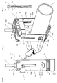
- FIGS. 1a-1d show a pipe clamp 1, which comprises a mounting part 12 and a receiving part 11, which are made in one piece from a metal sheet and without screws positively connected with each other and are releasable again.
- the mounting part 12 is formed into a U-profile and comprises a base plate 122 provided with a mounting opening 125 and two side walls 121 adjoining on both sides thereof, 123.
- the receiving part 11 comprises a holding the line 6 serving and at least approximately V-shaped receiving segment 111 and on both sides outwardly projecting connecting elements 112 which are arranged on at least approximately mutually parallel side pieces 110 of the receiving part 11.
- the connecting elements 112 engage positively each in an opening 126 in the side walls 121, 123 of the mounting part 12, between which the receiving part 11 either with the receiving segment 111 facing the mounting part 12 or facing away from this receiving segment 111 can be mounted.
- connecting elements 112, 126 can be used in various embodiments.
- FIG. 1a shows the pipe clamp 1 in a first configuration, with the mounted on a ceiling 71 mounting member 12 which is connected to the receiving part 11, such that the V-shaped receiving segment 111 facing away from the mounting part 12; ie the V-shaped receiving segment 111 has in the form of an arrow away from the mounting part 12.
- the installed line 6 is completely enclosed by the receiving part 11 and the mounting part 12 and remains securely in case of fire.
- the fixation of the installed line 6 takes place by means of a cable tie 2, which is inserted into openings 113 of the receiving part 11.
- the installed line 6 can therefore be used together with the receiving part 11 in the mounting part 12 and released from this again. This is particularly advantageous if the line 6 is installed temporarily or, for example, should be able to be quickly uninstalled for a check.
- FIG. 1b shows the pipe clamp 1 mounted on a wall 72 in the configuration of FIG. 1a .
- an L-shaped bracket 2 is provided which is slidably mounted on a side wall 123 of the mounting member 12, for example in the opening 125, and guided against the conduit 6 and can be fixed, for example by means of a wing nut.
- an elastic bearing element 119 is placed, which serves the gentle storage of the line 6.
- Figure 1c shows the clamp 1 of FIG. 1a in a second configuration with the mounted on the bottom 73 or on an object and upwardly open mounting part 12, in which the receiving part 11 is inserted such that the receiving segment 111 faces the mounting part 12.
- the installed conduit 6 is supported by the receiving segment 111, after which it can be fixed by means of a cable tie 2.
- This configuration of the pipe clamp 1 allows a conventional storage of the conduit 6, which is often realized in the construction industry. Since the line 6 is supported by the pipe clamp 1, there is no danger that it will come off the pipe clamp in case of fire, even if the cable tie 2 is destroyed.
- Figure 1d shows the pipe clamp 1 mounted on a wall 72 in the configuration of FIG Figure 1c , Furthermore, it is shown in this exemplary embodiment that the conduit 6 is held by a U-shaped retaining bracket 33 which has been inserted into openings 113 of the receiving part 11.
- the pipe clamp 1 can therefore be installed on the floor 73, on a wall 72 or on a profile carrier.
- the clamp 1 can therefore be adapted either to the requirements of the installer and mounted in hard to reach places.
- FIG. 2a shows a further embodiment of the pipe clamp 1 in the configuration in which the receiving segment 111 faces away from the mounting part 12.
- the connecting elements 126 parts of the side walls 121, 123 are shifted from each other to create a space between the wall 72 and the adjoining side wall 121.
- the connecting elements 126 are provided as simple openings at the lower ends of the side walls 121, 123, through which the hook-shaped connecting elements 112 of the receiving part 11 can be guided.
- the wall 72 facing the connecting element 112 protrudes unhindered into the space between the wall 72 and the side wall 121 inside.
- FIG. 2a further shows an L-shaped headband 2, which has a longitudinal slot 220 through which a retaining screw 81 is guided, which is further guided through openings or recesses in the receiving part 11 and / or in the mounting part 12.
- the headband 2 is guided through between the end pieces of the receiving part 11 and the mounting part 12, which are pressed against the headband 33 by means of a wing nut 82 placed on the retaining screw 81. In this way, the receiving part 11 and the mounting part 12, in addition to the connection with the connecting elements 112, 126, mutually fixed.
- FIG. 2b shows the mounted on the bottom 73 pipe clamp 1 of FIG. 2a in the configuration in which the receiving segment 111 faces the mounting part 12. It can be seen that the advantageous connection between the headband 33, the receiving part 11 and the mounting part 12 by the retaining screw 81 and the wing nut 82 as in FIG. 2a was realized.
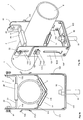
- FIGS. 3a and 3b show a pipe clamp 1 according to the invention in a further preferred embodiment, in which in turn a mounting part 12 and a receiving part 11 are provided, which in turn by connecting elements 112; 1121, 1122 and 126 are positively connected with each other. Furthermore, a closure element 2 is provided in the embodiment of a retaining clip, by means of which an installed line 6 is fixed.
- the U-shaped mounting member 12 which in the Figures 7a, 7b and 7c is shown isolated, is made of a thin sheet metal and has a base plate 122 to which a perpendicular thereto aligned side wall 121 and 123 connects on each side.
- the base plate 123 is provided with two reinforcing beads 1221 extending from one to the other side wall 121, 123. Between the two beads 1221, the mounting hole 125 is provided, in which a mounting screw 91 or a threaded anchor is fastened by means of nuts 92.
- the beads 1221 ensures that the thin base plate 122 can not bend even under the influence of load in case of fire. Despite the low material thickness, the base plate therefore has a high flexural strength.
- the side walls 121, 123 of the mounting part 12 are loaded only on train and do not bend under load even in case of fire, could be dispensed with the formation of beads.
- the side walls 121, 123 have on the underside a rectangular first opening 126 and closer to the base plate 122 a slot-shaped second opening 1260 which has the shape of an "L" whose foot element faces the base plate 122 and forms a parking space 1261.
- a hook-shaped connecting element 1121 and a locking element 1122 are held, which are each arranged on a side piece 110 of the receiving part 11.
- each a retaining screw 81 is guided, by means of which a headband 2 between the side walls 121, 123 and held along the second opening 1260, down against the installed line 6 and up to the parking space 1260 each retaining screw 81 is mobile.
- the in Figure 7a shown separately has a U-profile with a hold-down 21, connect to the both sides by 90 ° angled side elements 22, which are each provided with a threaded hole 220, in which engage the two retaining screw 81.
- the parking space 1261 of the second opening 1260 and the side members 22 of the retaining clip 2 allow the hold-down member 21 provided with an elastic member 28 to move sideways and pivot so as to expose the space below the base plate 122 and access to the mounting screw 91 and the associated nuts 92 is kept free.
- the further space between the side walls 121, 123 is also kept free, so that manipulations with the receiving part 11 and the line to be installed 6 are not hindered.
- the pipe clamp 1 is delivered with such pre-assembled or parked headband 2.
- the side walls 121, 123 have outwardly projecting short wing pieces 120, which allow the receiving part 11 to slide freely into the mounting part 12.
- FIG. 8a, 8b and 8c Sporadically shown integrally formed from sheet metal receiving part 11 has a V-shaped receiving segment 111, connect to the two-sided ends side pieces 110 which extend parallel to the side walls 121, 123 of the mounting member 12.
- the receiving segment 111 is provided with two beads 1110 which give the receiving segment 111 a high flexural strength even in the event of fire.
- the side pieces 110 are flat plates which at the top have a longitudinal slot 1101 opened against the base plate 122 of the mounting part 12, which is parallel to the lower part of the second opening 1260 in the side walls 121, 123 of the mounting part 12 runs.
- the receiving part 11 can therefore be inserted from below into the mounting part 12, after which the retaining screws 81 of the retaining clip 2 not only in the second opening 1260 of the side walls 121,123 of the mounting member 12, but also in the longitudinal slot 1101 is displaceable. Like this in the FIGS. 3a and 3b is shown, the side walls 121, 123 of the mounting part 12 and on the inside adjacent thereto side pieces 110 of the receiving part 11 are pressed after tightening the retaining screws 81 against the side members 22 of the retaining clip 2.
- the side pieces 110 are as in FIG. 8c shown in detail, each provided with a downwardly directed hook 1121 and an upwardly directed locking element 1122, which can engage in the first opening 126 in the side walls 121, 123 of the mounting part 12.
- the hook 1121 and locking elements 1122 are cut out of the side walls 121, 123 and pushed outwards.
- the elastic side walls 121, 123 of the mounting member 12 are pressed apart until the hooks 1121 can engage in the first opening 126 and the side walls 121, 123 again rotate against each other until they rest against the locking elements 1122. If the receiving part 11 is now pulled down, then the locking elements 1122 can also penetrate into the first opening 126.
- the locking elements 1122 is now prevented that the receiving part 11 can be pushed back up and the hooks 1121 can be solved from the first opening 126 of the side walls 121, 123.
- the retaining screws 81 by means of which the headband 2 is fixed, the side walls 121, 123 and the side pieces 110 are pressed together, so that the locking elements 1122 can not solve or extend.
- the side walls 121, 123 and the side pieces 110 are therefore after the assembly therefore on the one hand by the connecting elements 1121, 1122, 126 form-fitting and on the other hand by the retaining screws 81st at least positively connected with each other. If the side walls 121, 123 and the side pieces 110 are provided with mutually corresponding recesses, results in a further positive connection.
- the installed pipe clamp 1 is therefore optimally secured in case of fire.
- Figure 4c is shown in a detailed view that the side walls 121, 123 and the side pieces 110 are preferably provided with mutually corresponding deformations, eg teeth, which can engage with each other.
- the retaining screws 81 When pressing the thus configured side walls 121, 123 and side pieces 110 after tightening the retaining screws 81 is not only a frictional, but also a positive connection between these parts. This avoids that the retaining screws 81 are subjected to shear. In this case, the receiving part 11 can still be easily inserted into the mounting part 12.
- FIGS. 5a and 5b show the mounted on a wall clamp 1 of FIG. 3 holding a vertically or horizontally oriented pipe 6.
- FIG. 5c shows the already described connecting elements 126, 1121, 1122, by means of which the mounting part 12 and the receiving part 11 are screwless and positively connected with each other, in a detailed spatial view.
- FIG. 6a and 6b show the clamp 1 of FIG. 3 with the mounted on the ground or on an object mounting part 12, in which the receiving part 11 is suspended in such a way that the receiving segment 111 faces the mounting part 12.
- the tube 6 is inserted, which is fixed to the headband 2.
- the headband 2 is connected by means of the retaining screws 81 with the side pieces 110 of the receiving part 11.
- the retaining screws 81 are guided only in the slot openings 1101 of the side pieces 110, the overhang the mounting part 12.
- the connecting elements 1121, 1122 are in the same manner, but rotated by 180 ° in the first openings 126 of the side walls 121, 123 held.
- FIG. 7a, 7b, 7c and 7c show the mounting part 12 and the bracket 2 of the pipe clamp 1 of FIG. 3 from different perspectives
- FIGS. 8a and 8b show the receiving part 11 of the pipe clamp 1 of FIG. 3 from different perspectives.
- FIG. 8c shows the already described connecting elements 126, 1121, 1122, by means of which the mounting part 12 and the receiving part 11 are screwless and positively connected with each other, in a detailed view from the side.
- FIG. 9 shows the mounting member 12 and the inserted receiving part 11 with a two insulation shells 5a, 5b existing fire protection insulation.
- the mutually complementary insulation shells 5a, 5b which are made, for example, of a fiber composite material or a foamed plastic, such as polyethylene, polystyrene, neopor, polyurethane, are shaped such that they cover the metal structure of the pipe clamp 1.
- the free space above the installed line 6 is preferably used to couple the two insulation shells 5a, 5b, the corresponding coupling elements 51, 52 and a recess for receiving the line 6 with each other.
- the insulation shells 5a, 5b are held by the wing elements 120. Furthermore, further outwardly directed holding elements can be provided, which engage or cut into the material of the insulation shells 5a, 5b.
Description
Die Erfindung betrifft eine Rohrschelle.The invention relates to a pipe clamp.
Rohrschellen dienen der Installation von Leitungen, insbesondere Rohren, welche fest mit einem Baukörper zu verbinden und an einer Montageposition stabil zu halten sind. Dabei sind verschiedene Einsatzkriterien zu beachten. Besonders wichtig sind die mechanische Belastbarkeit insbesondere auch im Brandfall sowie die Handhabbarkeit der Rohrschelle. Diese soll schnell, sicher und komfortabel montierbar sein und die installierte Leitung zuverlässig halten.Pipe clamps are used for the installation of pipes, in particular pipes, which are to be firmly connected to a building and to be kept stable at a mounting position. There are different application criteria to be considered. Particularly important are the mechanical strength especially in case of fire and the handling of the pipe clamp. This should be fast, safe and easy to install and keep the installed cable reliable.
Teil 12 der Norm DIN 4102 beschreibt die Anforderungen, Prüfungen und Massnahmen zur Erzielung des Funktionserhaltes von elektrischen Kabelanlagen im Brandfall. Diese Norm ermöglicht somit die Prüfung einer kompletten Kabelanlage unter praxisgerechten Bedingungen. Dazu gehören isolierte Starkstromleitungen, Installationsleitungen für Fernmelde- und Informationsverarbeitungsanlagen sowie Rohre und, die dazu gehörigen Verbindungselemente, Tragevorrichtungen und Halterungen.
Von Fachleuten wird darauf hingewiesen, dass gerade die "Kleinteile", wie brandschutztechnisch geprüfte Dübel und Schrauben, in diesem Zusammenhang eine wichtige Rolle spielen. Denn jede Kabelanlage kann nur so gut sein, wie ihr schwächstes Glied.It is pointed out by experts that the "small parts", such as dowels and screws that have been tested in terms of fire protection, play an important role in this context. Because every cable system can only be as good as its weakest link.
In [1], Peter Nause, Brandverhalten von Befestigungssystemen in der Installationstechnik, Materialprüfanstalt für das Bauwesen, Braunschweig, ist ausgeführt, dass bei Prüfungen festgestellt wurde, dass sich selbst metallene Teile von Rohrschellen im Brandfall erheblich deformieren und voneinander lösen können.In [1], Peter Nause, Fire behavior of fastening systems in the installation technology, material testing institute for the construction industry, Braunschweig, it is stated that during tests it was found that even metal parts of In the event of a fire, clamps can be significantly deformed and detached from one another.
Aus [2],
Aus [3],
Aus [5],
Aus [7],
Aus [9],
Aus [10],
Der vorliegenden Erfindung liegt daher die Aufgabe zugrunde, eine verbesserte Rohrschelle zu schaffen, welche auch im Brandfall ein gesichertes Halten einer installierten Leitung oder eines Rohres gewährleistet.The present invention is therefore an object of the invention to provide an improved pipe clamp, which ensures a secure hold an installed pipe or pipe even in case of fire.
Insbesondere ist eine einfach aufgebaute und mit minimalem Aufwand herstellbare Rohrschelle zu schaffen, die unter verschiedenen Installationsbedingungen vielseitig montierbar ist, und die eine Installation von Leitungen und Rohren mit unterschiedlichem Durchmesser erlaubt.In particular, a simple design and can be produced with minimal effort pipe clamp is created, which is versatile mountable under different installation conditions, and allows installation of pipes and pipes with different diameters.
Der Installationsvorgang soll rasch und komfortabel durchführbar sein, so dass eine Installation, insbesondere eine provisorische Installation, welche ein sicheres Halten einer Leitung oder eines Rohres gewährleistet, sowie die entsprechende Deinstallation mit nur einem Handgriff möglich sind.The installation process should be carried out quickly and conveniently, so that an installation, in particular a temporary installation, which ensures a secure holding a pipe or a pipe, and the corresponding deinstallation are possible with just one hand.
Diese Aufgabe wird mit einer Rohrschelle gelöst, welche die in Anspruch 1 angegebenen Merkmale aufweist. Vorteilhafte Ausgestaltungen der Erfindung sind in weiteren Ansprüchen angegeben.This object is achieved with a pipe clamp having the features specified in
Die Rohrschelle, die eine für den Brandfall gesicherte Installation einer Leitung, insbesondere eines Rohres, erlaubt, umfasst ein Montageteil und ein Aufnahmeteil, die einstückig aus einem Metallblech geformt und miteinander verbindbar sind und die dem Halten der installierten Leitung dienen.The pipe clamp, which allows for a fire-proof installation of a pipe, in particular a pipe, comprises a mounting part and a receiving part, which are integrally formed from a metal sheet and connectable to each other and serve to hold the installed line.
Erfindungsgemäss umfasst das U-Profil-förmige Montageteil eine mit wenigstens einem Montageelement versehene Grundplatte sowie zwei Seitenwände. Das Aufnahmeteil weist ein dem Halten der Leitung dienendes und zumindest annähernd V-förmiges Aufnahmesegment sowie beidseitig nach aussen ragende Verbindungselemente auf, die formschlüssig je in eine Öffnung in den Seitenwänden des Montageteils eingreifen, zwischen denen das Aufnahmeteil wahlweise mit dem Aufnahmesegment dem Montageteil zugewandt oder von diesem abgewandt montierbar ist.According to the invention, the U-shaped mounting part comprises a base plate provided with at least one mounting element and two side walls. The receiving part has a holding the line serving and at least approximately V-shaped receiving segment and on both sides outwardly projecting connecting elements which engage positively each in an opening in the side walls of the mounting part, between which the receiving part selectively facing the mounting part or from this is facing away mountable.
Die Fertigung des Montageteils und des Aufnahmeteils einstückig aus einem Metallblech ist mit geringem Aufwand an Material und Arbeit möglich. Durch die Wahl von Metallblech wird ein Ausgangsmaterial verwendet, welches eine hohe Brandfestigkeit aufweist. Vorzugsweise werden Bleche aus rostfreiem Stahl oder auch normale oder hochwarmfeste Stähle verwendet, welche mit einer Schutzschicht, wie Zink versehen sind.The manufacture of the mounting part and the receiving part in one piece from a metal sheet is possible with little effort on material and work. By the choice of metal sheet, a starting material is used, which has a high fire resistance. Preferably, stainless steel sheets or normal or high-temperature steels are used, which are provided with a protective layer, such as zinc.
Die Wahl eines U-Profils für das Montageteil ist hinsichtlich eines Brandfalls besonders vorteilhaft. Bei der Verwendung eines U-Profils, vorzugsweise eines U-Profils mit verstärkter Grundplatte, erfolgt anstelle einer Deformation lediglich eine Dehnung der Montageteils, die für den Funktionserhalt der Rohrschelle unkritisch ist. Eine wirksame Verstärkung der Grundplatte, selbst bei dünnem Blech kann durch das Einprägen von Sicken realisiert werden, welche der Grundplatte eine um ein mehrfaches höhere Biegesteifigkeit verleihen.The choice of a U-profile for the mounting part is particularly advantageous in terms of fire. When using a U-profile, preferably a U-profile with reinforced base plate, instead of deformation, only an expansion of the mounting part, which is not critical to the functional integrity of the pipe clamp. An effective reinforcement of the base plate, even with thin sheet metal can be realized by the embossing of beads, which give the base plate to a multiple higher bending stiffness.
Die Wahl eines Aufnahmeteils mit einem zumindest annähernd V-förmigen Aufnahmesegment erlaubt es, Leitungen und Rohre mit unterschiedlichem Durchmesser aufzunehmen und stabil zu halten. Die Leitungen und Rohre liegen daher am Aufnahmesegment und nicht am Montageteil an.The choice of a receiving part with an at least approximately V-shaped receiving segment allows to accommodate pipes and pipes of different diameters and to keep stable. The pipes and pipes are therefore on the receiving segment and not on the mounting part.
Die am Aufnahmeteil beidseitig nach aussen ragenden Verbindungselemente, die formschlüssig je in eine Öffnung in den Seitenwänden des Montageteils eingreifen können, erlauben es, das Aufnahmeteil mit einem Handgriff in das Montageteil einzuhängen. Erfindungsgemäss sind das Montageteil und das Aufnahmeteil derart dimensioniert und ausgestaltet, dass das Aufnahmeteil wahlweise mit dem Aufnahmesegment dem Montageteil zugewandt oder von diesem abgewandt mit dem Montageteil verbunden werden kann. Dadurch eröffnen sich zahlreiche vorteilhafte Möglichkeiten zur Montage der Rohrschelle sowie zur Handhabung einer zu installierenden Leitung.The on the receiving part on both sides outwardly projecting connecting elements, which can positively engage each in an opening in the side walls of the mounting part, allow to mount the receiving part with a handle in the mounting part. According to the invention, the mounting part and the receiving part are dimensioned and configured such that the receiving part can be selectively connected to the receiving part facing the mounting part or facing away from this with the mounting part. This opens up numerous advantageous possibilities for mounting the pipe clamp and for handling a cable to be installed.
Das Montageteil wird vorzugsweise mit nur einer Montageschraube montiert, welche z.B. mittels Schraubenmuttern mit der Grundplatte des Montageteils verbunden ist. Die Montageschraube, zum Beispiel eine Gewindestange oder ein Betonanker, kann in der Decke, einer Wand oder im Boden eines Raumes oder an einer beliebigen Seite eines Gegenstandes verankert werden. Die Möglichkeit zum wahlweisen Einsetzen des Aufnahmeteils erlaubt es nun, die Leitung oder das Rohr in einer passenden Weise zu installieren. Sofern das am Boden oder auf einem Gegenstand montierte Montageteil nach oben geöffnet ist, kann das Aufnahmeteil mit dem Aufnahmesegment dem Montageteil zugewandt in das Montageteil eingesetzt werden. Anschliessend kann die Leitung auf das Aufnahmesegment aufgelegt werden, so dass diese vom Aufnahmesegment gestützt wird. Sofern das an der Decke befestigte Montageteil nach unten geöffnet ist, wird das Aufnahmeteil mit dem vom Montageteil abgewandten Aufnahmesegment in das Montageteil eingehängt. In beiden frei wählbaren Montagevarianten kann das Aufnahmeteil oder das Aufnahmeteil zusammen mit der Leitung mit einem Handgriff installiert werden.The mounting part is preferably mounted with only one mounting screw, which e.g. is connected by means of nuts with the base plate of the mounting part. The mounting screw, for example a threaded rod or a concrete anchor, can be anchored in the ceiling, a wall or in the floor of a room or on any side of an object. The ability to selectively insert the receiving part now allows the conduit or pipe to be installed in a convenient manner. If the mounting part mounted on the floor or on an object is opened upwards, the receiving part can be inserted with the receiving segment facing the mounting part into the mounting part. Subsequently, the line can be placed on the receiving segment, so that it is supported by the receiving segment. If the mounted on the ceiling mounting part is open downwards, the receiving part is mounted with the receiving part facing away from the mounting part in the mounting part. In both freely selectable installation variants, the receiving part or the receiving part can be installed together with the line with a handle.
Durch die formschlüssige Verbindung zwischen dem Montageteil und dem Aufnahmeteil wird gewährleistet, dass sich das Aufnahmeteil und somit die installierte Leistung auch in einem Brandfall nicht vom Montageteil lösen kann. Die Fixierung der Leitung kann dabei in verschiedener Weise erfolgen. Einerseits sind Kabelbinder einsetzbar, welche die installierte Leitung fest mit dem Aufnahmeteil verbinden. Andererseits kann ein Abschlusselement aus Metall, wie ein U- oder L-förmiger Bügel verwendet werden.Due to the positive connection between the mounting part and the receiving part ensures that the receiving part and thus the installed power in one Fire can not solve the mounting part. The fixation of the line can be done in various ways. On the one hand, cable ties are used, which connect the installed cable firmly with the receiving part. On the other hand, a metal closure member such as a U-shaped or L-shaped bracket may be used.
Die Rohrschelle ist daher so flexibel einsetzbar, dass mit einer einzigen Rohrschelle praktisch alle relevanten Installationsanforderungen berücksichtigt werden können.The pipe clamp can therefore be used so flexibly that virtually all relevant installation requirements can be taken into account with a single pipe clamp.
Erfindungsgemäß weist das Aufnahmeteil zwei an das Aufnahmesegment anschliessende und zumindest annähernd zueinander parallele Seitenstücke auf, die vorzugsweise mit nach aussen gerichteten Haken versehen sind, welche durch die vorzugsweise rechteckigen Öffnungen in den Seitenwänden des Montageteils hindurch greifen. Die beiden Seitenstücke liegen an den Seitenwänden des Montageteils an, nachdem die als Verbindungselemente dienenden Haken in die Öffnungen eingeführt wurden.According to the invention, the receiving part has two adjoining the receiving segment and at least approximately parallel side pieces, which are preferably provided with outwardly directed hooks which engage through the preferably rectangular openings in the side walls of the mounting part. The two side pieces abut against the side walls of the mounting part, after the connecting elements serving as hooks were inserted into the openings.
In einer weiteren bevorzugten Ausgestaltung sind die beiden Seitenstücke des Aufnahmeteils zusätzlich zu den Haken mit nach aussen gerichteten Rastelementen versehen, die derart angeordnet sind, dass sie an der Seite in die Öffnungen in den Seitenwänden des Montageteils hineinragen, die der Seite der Öffnungen gegenüberliegt an der die Haken anliegen. Durch die Rastelemente wird gewährleistet, dass sich die Haken nicht selbsttätig aus den Öffnungen lösen können. Durch Zurückbiegen der Seitenwände des Montageteils können die Rastelemente gelöst und das Aufnahmeteil aus dem Montageteil ausgehängt werden. Auf diese Weise gelingt eine einfache und vorteilhafte Sicherung der Verbindung, welche noch zusätzlich gesichert werden kann, indem die Seitenstücke des Aufnahmeteils und die Seitenwände des Montageteils, die vorzugsweise plattenförmig ausgestaltet sind und zumindest annähernd parallel aneinander anliegen, z.B. mittels Verschraubung gegeneinander gepresst werden.In a further preferred embodiment, the two side pieces of the receiving part are provided in addition to the hooks with outwardly directed locking elements which are arranged so that they protrude at the side in the openings in the side walls of the mounting part, which is opposite to the side of the openings on the the hooks rest. By the locking elements ensures that the hooks can not solve themselves from the openings. By bending back the side walls of the mounting part, the locking elements can be released and the receiving part can be unhooked from the mounting part. In this way, a simple and advantageous securing the connection, which can be additionally secured by the side pieces of the receiving part and the side walls of the mounting part, which are preferably designed plate-shaped and at least approximately parallel to each other abutment, for example, by means of screwing pressed against each other.
Diese zusätzliche Sicherung wird erfindungsgemäss anhand eines der Fixierung der Leitung dienenden Haltebügels realisiert, welcher beidseitig je mit einer Halteschraube versehen ist, durch die jede Seitenwand des Montageteils gegen das entsprechende Seitenstück des Aufnahmeteils und den Haltebügel drückt. Nach der Montage des Haltebügels liegen die Seitenwände und die Seitenstücke aneinander an, weshalb das Rastelement in der Öffnung gehalten bleibt und der Haken nicht gelöst werden kann. Durch die Montage des Haltebügels resultiert zudem eine zweite, zumindest kraftschlüssige Verbindung zwischen dem Montageteil und dem Aufnahmeteil. Eine zusätzliche formschlüssige Verbindung kann erzielt werden, indem die Seitenwände und die Seitenstücke mit ineinander eingreifenden Verformungen versehen werden. Die installierte Rohrschelle ist nach der Installation daher doppelt gegen ein im Brandfall zu vermeidendes Auftrennen geschützt.This additional backup is realized according to the invention by means of a fixation of the line serving retaining clip, which is provided on both sides each with a retaining screw through which presses each side wall of the mounting member against the corresponding side piece of the receiving part and the headband. After mounting the retaining clip, the side walls and the side pieces abut each other, which is why the locking element is held in the opening and the hook can not be solved. By mounting the retaining bracket also results in a second, at least positive connection between the mounting part and the receiving part. An additional positive connection can be achieved by providing the side walls and the side pieces with intermeshing deformations. The installed pipe clamp is thus protected twice after installation to avoid a fire in case of fire separation.
Der Haltebügel umfasst ein an der installierten Leitung anliegendes Niederhalteteil und beidseits davon jeweils ein daran anschließendes Seitenelement, welches mit einer Öffnung oder einer Gewindebohrung versehen ist, durch die eine Halteschraube geführt ist, mittels der der Haltebügel zumindest mit dem Aufnahmeteil und/oder dem Montageteil verbunden ist. Durch die Halteschraube, die in die Gewindebohrung im Seitenelement des Haltebügels eingreift, werden die zugehörige Seitenwand des Montageteils und das zugehörige Seitenstück des Aufnahmeteils gegen den Haltebügel gepresst.The headband includes a voltage applied to the installed line hold-down and on both sides thereof an adjoining side member which is provided with an opening or a threaded hole through which a retaining screw is guided, connected by means of the headband at least with the receiving part and / or the mounting part is. By the retaining screw which engages in the threaded hole in the side member of the retaining bracket, the associated side wall of the mounting member and the associated side piece of the receiving part are pressed against the headband.
Zur Durchführung der Halteschraube weisen die Seitenwände des Montageteils gesonderte Öffnungen auf, die in sich geschlossen sind. In die ersten Öffnungen in den Seitenwänden greifen daher die Haken und die Rastelemente des Aufnahmeteils ein. In den davon gesonderten zweiten Öffnungen sind hingegen die Halteschrauben des Haltebügels derart geführt, dass der Haltebügel entlang den Seitenwänden des Montageteils nach oben und nach unten geführt werden kann. Die als Längsschlitz ausgestaltete zweite Öffnung verläuft nahe der Grundplatte vorzugsweise in einer Kurve, welche es erlaubt, den Haltebügel in einen Parkraum zur Seite zu führen und dort zu fixieren. Sofern der Haltebügel zusätzlich zur Seite gedreht wird, wird der Raum unterhalb der Grundplatte frei gegeben, so dass mit einem Werkzeug auf die Montageschraube zugegriffen werden kann. Nach der Installation der Rohrschelle kann der Haltebügel gelöst, gedreht und gegen die Leitung gefahren werden.To carry out the retaining screw, the side walls of the mounting part on separate openings, which are self-contained. In the first openings in the side walls therefore engage the hook and the locking elements of the receiving part. In the separate second openings on the other hand, the retaining screws of the retaining clip are guided such that the headband along the side walls of the mounting member can be guided upwards and downwards. The configured as a longitudinal slot second opening runs near the base plate preferably in a curve, which allows to guide the headband in a parking space to the side and to fix it. If the headband is rotated in addition to the side, the space below the base plate is released, so that can be accessed with a tool on the mounting screw. After installing the pipe clamp, the headband can be loosened, turned and driven against the pipe.
Die Seitenstücke des Aufnahmeteils weisen auf der dem Aufnahmesegment abgewandten Seite je einen nach aussen geöffneten Montageschlitz auf, welcher parallel zur zweiten Öffnung in der zugehörigen Seitenwand des Montageteils verläuft. Die Halteschrauben können daher aus dem Parkraum gefahren und entlang dem zugehörigen Längsschlitz in den Seitenwänden des Montageteils in die nach aussen geöffneten Montageschlitze in den Seitenstücken des Aufnahmeteils gefahren werden.The side pieces of the receiving part have on the side facing away from the receiving segment depending on an outwardly open mounting slot, which runs parallel to the second opening in the associated side wall of the mounting part. The retaining screws can therefore be moved out of the parking space and driven along the associated longitudinal slot in the side walls of the mounting part in the open to the outside mounting slots in the side pieces of the receiving part.
Sofern das Aufnahmeteil mit dem Aufnahmesegment dem Montageteil zugewandt in das z.B. am Boden montierte Montageteil eingesetzt wird, liegen die Seitenstücke des Aufnahmeteils vorzugsweise frei, so dass der Haltebügel in das Aufnahmeteil eingesetzt werden kann, indem die Halteschrauben in die Montageschlitze eingeführt werden.If the receiving part with the receiving segment facing the mounting part in the e.g. is used at the bottom mounting part, the side pieces of the receiving part are preferably exposed, so that the headband can be inserted into the receiving part by the retaining screws are inserted into the mounting slots.
Zur schonenden Lagerung der installierten Leitung sind das Aufnahmesegment des Aufnahmeteils und das Niederhalteteil des Haltebügels vorzugsweise mit wenigstens einem elastischen Element versehen.For gentle storage of the installed line, the receiving segment of the receiving part and the hold-down part of the retaining clip are preferably provided with at least one elastic element.
Nachfolgend wird die Erfindung anhand von Zeichnungen näher erläutert. Dabei zeigt:
- Fig. 1a
eine Rohrschelle 1 in einer ersten Konfiguration, mit einem aneiner Decke 71 montierten Montageteil 12, dasmit dem Aufnahmeteil 11, derart verbunden ist, dass das V-förmige Aufnahmesegment 111vom Montageteil 12 abgewandt ist;- Fig. 1b
- die an
einer Wand 72montierte Rohrschelle 1 in der Konfiguration vonFigur 1a mit einem Haltebügel 2, dervon einer Seitenwand 123 desMontageteils 12 gehalten ist; - Fig. 1c
- die
Rohrschelle 1 vonFigur 1a in einer zweiten Konfiguration mit dem amBoden 73 montierten und nach oben geöffneten Montageteil 12 und demdarin eingesetzten Aufnahmeteil 11 mitdem dem Montageteil 12zugewandten Aufnahmesegment 111; - Fig. 1d
- die an
einer Wand 72montierte Rohrschelle 1 in der Konfiguration vonFigur 1c ; - Fig. 2a
- eine an
der Wand 72montierte Rohrschelle 1 in einer weiteren Ausgestaltungmit einem Haltebügel 2, der mittels einer Halteschraube 81mit dem Aufnahmeteil 11und dem Montageteil 12 verbunden ist; - Fig. 2b
- die
am Boden 73montierte Rohrschelle 1 vonFigur 2a ; - Fig. 3 a-b
- eine erfindungsgemäße Ausgestaltung der Rohrschellen 1 von
Figur 1b und2a mit dem an einer Decke montierten Montageteil 12, inwelches das Aufnahmeteil 11 derart eingehängt ist, dass das V-förmige Aufnahmesegment 111vom Montageteil 12 abgewandt ist; - Fig. 4 a-b
- die
Rohrschelle 1 vonFigur 3 mit parkiertem Haltebügel 2; - Fig. 5 a-b
- die an einer
Wand montierte Rohrschelle 1 vonFigur 3 , die ein vertikal bzw.horizontal ausgerichtetes Rohr 6 hält; - Fig. 5c
Verbindungselemente das Montageteil 12und das Aufnahmeteil 11 schraubenlos und formschlüssig miteinander verbunden sind;- Fig. 6 a-b
- die
Rohrschelle 1 vonFigur 3 mit dem am Boden oder auf einen Gegenstand montierten Montageteil 12, inwelches das Aufnahmeteil 11 derart eingehängt ist, dassdas Aufnahmesegment 111 dem Montageteil 12 zugewandt ist; - Fig. 7 a-d
das Montageteil 12 undden Haltebügel 2der Rohrschelle 1 vonFigur 3 aus verschiedenen Blickrichtungen;- Fig. 8 a-c
das Aufnahmeteil 11der Rohrschelle 1 vonFigur 3 aus verschiedenen Blickrichtungen; und- Fig. 9
das Montageteil 12 unddas eingesetzte Aufnahmeteil 11 mit einer zweischaligen Brandschutzisolation.
- Fig. 1a
- a
pipe clamp 1 in a first configuration, with a mounted on aceiling 71 mountingmember 12 which is connected to the receivingpart 11, such that the V-shapedreceiving segment 111 facing away from the mountingpart 12; - Fig. 1b
- the
pipe clamp 1 mounted on awall 72 in the configuration of FIGFIG. 1a with abracket 2, which is held by aside wall 123 of the mountingpart 12; - Fig. 1c
- the
clamp 1 ofFIG. 1a in a second configuration with the mounted on the bottom 73 and upwardly open mountingmember 12 and the receivingpart 11 inserted therein with the mountingmember 12 facing receivingsegment 111; - Fig. 1d
- the
pipe clamp 1 mounted on awall 72 in the configuration of FIGFigure 1c ; - Fig. 2a
- a mounted on the
wall 72pipe clamp 1 in a further embodiment with aheadband 2, which is connected by means of a retainingscrew 81 with the receivingpart 11 and the mountingpart 12; - Fig. 2b
- the mounted on the bottom 73
pipe clamp 1 ofFIG. 2a ; - Fig. 3 from
- an inventive embodiment of the pipe clamps 1 of
FIG. 1b and2a with the mounted on aceiling mounting member 12, in which the receivingpart 11 is suspended in such a way that the V-shapedreceiving segment 111 faces away from the mountingpart 12; - Fig. 4 from
- the
clamp 1 ofFIG. 3 with parkedheadband 2; - Fig. 5 from
- the mounted on a
wall clamp 1 ofFIG. 3 holding a vertically or horizontally orientedpipe 6; - Fig. 5c
-
Connecting elements part 12 and the receivingpart 11 are screwless and positively connected with each other; - Fig. 6 from
- the
clamp 1 ofFIG. 3 with the mounted on the ground or on anobject mounting part 12, in which the receivingpart 11 is suspended in such a way that the receivingsegment 111 faces the mountingpart 12; - Fig. 7 ad
- the mounting
part 12 and theheadband 2 of theclamp 1 ofFIG. 3 from different perspectives; - Fig. 8 ac
- the receiving
part 11 of thepipe clamp 1 ofFIG. 3 from different perspectives; and - Fig. 9
- the mounting
part 12 and the inserted receivingpart 11 with a double-shell fire protection insulation.
Die
Das Montageteil 12 ist zu einem U-Profil geformt und umfasst eine mit einer Montageöffnung 125 versehene Grundplatte 122 sowie zwei beidseitig daran anschliessende Seitenwände 121, 123. Das Aufnahmeteil 11 umfasst ein dem Halten der Leitung 6 dienendes und zumindest annähernd V-förmiges Aufnahmesegment 111 sowie beidseitig nach aussen ragende Verbindungselemente 112, die an zumindest annähernd parallel zueinander verlaufenden Seitenstücken 110 des Aufnahmeteils 11 angeordnet sind. Die Verbindungselemente 112 greifen formschlüssig je in eine Öffnung 126 in den Seitenwänden 121, 123 des Montageteils 12 ein, zwischen denen das Aufnahmeteil 11 wahlweise mit dem Aufnahmesegment 111 dem Montageteil 12 zugewandt oder von diesem abgewandt Aufnahmesegment 111 montierbar ist.The mounting
Zur Realisierung dieser formschlüssigen Verbindung zwischen dem Montageteil 12 und dem Aufnahmeteil 11, durch die sichergestellt wird, dass sich das Aufnahmeteil 11 auch im Brandfall und unter Last nicht vom Montageteil 12 löst, sind Verbindungselemente 112, 126 in verschiedenen Ausgestaltungen verwendbar.To realize this positive connection between the mounting
Auch in der Konfiguration, in der das Aufnahmesegment 111 dem Montageteil zugewandt ist, kann die Rohrschelle 1 daher am Boden 73, an einer Wand 72 oder an einem Profilträger installiert werden. Die Rohrschelle 1 kann daher wahlweise an die Anforderungen des Installateurs angepasst und auch an kaum zugänglichen Orten montiert werden.Even in the configuration in which the receiving
Die
Das U-Profil-förmige Montageteil 12, welches in den
Der in
Wie dies in den
An den von der Grundplatte 122 abgewandten Enden weisen die Seitenwände 121, 123 nach aussen ragende kurze Flügelstücke 120 auf, welche es erlauben, dass Aufnahmeteil 11 ungehindert in das Montageteil 12 einzuschieben.At the ends remote from the
Das in den
Auf der unteren Seite, nahe dem Aufnahmesegment 111, sind die Seitenstücke 110, wie in
In
Die
Die
Die
Die
- [1][1]
- Peter Nause, Brandverhalten von Befestigungssystemen in der Installationstechnik, Materialprüfanstalt für das Bauwesen, Braunschweig (undatiert)Peter Nause, Fire Behavior of Mounting Systems in Installation Technology, Materials Testing Institute for Civil Engineering, Braunschweig (undated)
- [2][2]
-
EP 1 741 965 A1 EP 1 741 965 A1 - [3][3]
-
WO 01/04529 A1WO 01/04529 A1 - [4][4]
-
FR2214343A5FR2214343A5 - [5][5]
-
DE102006033800A1DE102006033800A1 - [6][6]
-
CH 644436 A5CH 644436 A5 - [7][7]
-
EP 1 808 629 A2 EP 1 808 629 A2 - [8][8th]
-
FR 2880211 A1FR 2880211 A1 - [9][9]
-
EP 2 112 413 A1 EP 2 112 413 A1 - [10][10]
-
US 3,051,424 AUS 3,051,424 A
Claims (14)
- Pipe clamp (1) for the installation of a conduit (6), particularly a tube, that is secured for the case of fire, with a mounting member (12) that is formed in one piece from a metal sheet to a U-profile that comprises a base plate (122) having at least one mounting element (125; 91) as well as two sidewalls (121, 123) having slot-shaped openings (1260), and with a receiving member (11) that is formed in one piece from a metal sheet to a profile having an at least approximately V-shaped receiving segment (111) that serves for holding the conduit and with a holding bracket (2), wherein the conduit (6) can be fixed by means of the holding bracket (2), which comprises a down holding member (21), which abuts the conduit (6) and which comprises on both sides thereto adjoining side elements (22) having an opening (22) each, through which as well as through the slot-shaped openings (1260) holding screws (81) are guidable, wherein the receiving segment (111) is provided on both sides with side pieces (110), which are aligned approximately in parallel to one another, which comprise each on the side averted thereto a mounting slot (1101), that is open towards the outside, that serves for receiving the holding screw (81), that extends in parallel to the slot-shaped opening (1260) in the sidewall (121; 123) of the mounting member (12), and on which each a connecting element (112, 1221, 1222) is provided, that extends to the outside and that engages in a form locking manner in a further opening (126) in the related sidewall (121, 123) of the mounting member (12), wherein the receiving member (11) can be mounted between the sidewalls (121, 123) selectively with the receiving segment (111) facing the mounting member (12) or averted thereto.
- Pipe clamp (1) according to claim 1, characterised in that the receiving member (11) comprises two side pieces (110) that are adjoining the receiving segment (111) and that are aligned at least approximately in parallel to one another and that are provided with hooks (112, 1121), which extend towards the outside and which reach through the preferably rectangular openings (126) in the sidewalls (121, 123) of the mounting member (12).
- Pipe clamp (1) according to claim 2, characterised in that the two side pieces (110) of the receiving member (11) are provided, in addition to the hooks (1121), with catch elements (1122) that extend towards the outside and that are arranged in such a way that they extend at the side into the openings (126) of the sidewalls (121, 123) of the mounting member (12), which is opposite to the side of the openings (126) on which the hooks (1121) abut.
- Pipe clamp (1) according to claim 2 or 3, characterised in that the side pieces (110) of the receiving member (11) and the sidewalls (121, 123) of the mounting member (12) are plate-shaped and abut at least approximately in parallel at one another.
- Pipe clamp (1) according to one of the claims 1-4, characterised in that the base plate (122) of the mounting member (12) is provided with enforcing elements 1221, such as reinforcing fins, which extend from one sidewall (121) to the other sidewall (123) of the mounting member (12).
- Pipe clamp (1) according to one of the claims 1-5, characterised in that the holding bracket (2) is connected by means of the holding screw (81) to the side pieces (110) of the receiving member (11), when the receiving segment (111) is facing the base plate (122), and that the holding bracket (2) is connected with the sidewalls (121, 123) of the mounting member (12) and the side pieces (110) of the receiving member (11), when the receiving segment (111) is averted from the mounting member (12).
- Pipe clamp (1) according to claim 6, characterised in that the holding bracket (2) is provided with a U-shape.
- Pipe clamp (1) according to claim 6 or 7, characterised in that the slot-shaped opening (1260) in the sidewall (121; 123) of the mounting member (12) changes direction close to the base plate (122) preferably by 90° and enters into a parking space (1261).
- Pipe clamp (1) according to claim 8, characterised in that, when the receiving segment (111) is facing the mounting member (12), the side pieces (110) of the receiving member (11) lie free and hold the holding screws (81) of the holding bracket (2) within the mounting slots (1101).
- Pipe clamp (1) according to one of the claims 1-9, characterised in that a mounting opening (125) is provided at the base plate (122) of the mounting member (12), which serves for receiving a mounting screw (91).
- Pipe clamp (1) according to one of the claims 1-10, characterised in that the receiving segment (11) of the receiving member (11) and/or the down holding member (21) of the holding bracket (2) is or are provided with at least one elastic element (28 or 119).
- Pipe clamp (1) according to one of the claims 1-11, characterised in that the side pieces (110) of the receiving member (11) and the sidewalls (121, 123) of the mounting member (12) are provided with deformations, such as toothing, that correspond to one another.
- Pipe clamp (1) according to one of the claims 1-12, characterised in that the receiving segment (111) of the receiving member (11) is provided with at least one enforcing fin (1110), which preferably extends from one side piece (110) to the other.
- Pipe clamp (1) according to one of the claims 1 13, characterised in that a fire protection insulation with two insulation shells (5a, 5b) that correspond to one another is provided, which on the upper side comprise coupling elements (51, 52) engaging into one another and on the lower side a recess (53) serving for receiving the installed conduit (6).
Priority Applications (1)
| Application Number | Priority Date | Filing Date | Title |
|---|---|---|---|
| EP10161787.6A EP2325539B1 (en) | 2009-11-13 | 2010-05-03 | Multifunctional pipe clamp |
Applications Claiming Priority (2)
| Application Number | Priority Date | Filing Date | Title |
|---|---|---|---|
| EP09176003A EP2322830A1 (en) | 2009-11-13 | 2009-11-13 | Multifunctional pipe clamp |
| EP10161787.6A EP2325539B1 (en) | 2009-11-13 | 2010-05-03 | Multifunctional pipe clamp |
Publications (2)
| Publication Number | Publication Date |
|---|---|
| EP2325539A1 EP2325539A1 (en) | 2011-05-25 |
| EP2325539B1 true EP2325539B1 (en) | 2016-07-13 |
Family
ID=51417918
Family Applications (1)
| Application Number | Title | Priority Date | Filing Date |
|---|---|---|---|
| EP10161787.6A Not-in-force EP2325539B1 (en) | 2009-11-13 | 2010-05-03 | Multifunctional pipe clamp |
Country Status (1)
| Country | Link |
|---|---|
| EP (1) | EP2325539B1 (en) |
Families Citing this family (9)
| Publication number | Priority date | Publication date | Assignee | Title |
|---|---|---|---|---|
| CN103363190A (en) * | 2013-07-30 | 2013-10-23 | 中国人民解放军总后勤部油料研究所 | Pipeline wall pulley |
| DE102014001161A1 (en) * | 2014-01-31 | 2015-08-06 | Murrplastik Systemtechnik Gmbh | Holding device for long bodies, in particular for cables |
| CN106226082B (en) * | 2016-07-12 | 2019-03-08 | 中国航空工业集团公司沈阳发动机设计研究所 | A kind of fixed device of adjustable opposite opened test lead |
| NL2017894B1 (en) * | 2016-11-30 | 2018-06-11 | Walraven Holding Bv J Van | Pipe hanger |
| GB2572656B (en) * | 2018-08-17 | 2021-04-21 | Midland Fixings Ltd | Metal fastening for cables |
| EP3702652A1 (en) | 2019-02-27 | 2020-09-02 | Gerster, Gaby | Pipe clamp |
| EP3865749B1 (en) | 2020-02-16 | 2023-08-30 | Zurecon AG | Pipe clip |
| CN112827106B (en) * | 2021-01-29 | 2022-04-08 | 武汉凤安技术有限公司 | Hanging type fixing device for fire-fighting spray pipeline |
| US20240106212A1 (en) * | 2022-09-22 | 2024-03-28 | Panduit Corp. | Cable management system |
Family Cites Families (15)
| Publication number | Priority date | Publication date | Assignee | Title |
|---|---|---|---|---|
| US3051424A (en) | 1959-09-28 | 1962-08-28 | Duhamel Gerard | Pipe hanger |
| DE1851413U (en) * | 1962-03-15 | 1962-05-10 | Hilti Montage Technik Ges M B | PIPE CLAMP. |
| FR2214343A5 (en) | 1973-01-15 | 1974-08-09 | Gaillard Et Cie | |
| CH644436A5 (en) | 1981-11-03 | 1984-07-31 | Marc Luisier | Device for positioning pipes in a concrete slab |
| FR2520945B1 (en) * | 1982-01-29 | 1985-07-05 | Essilor Int | DEVICE FOR FIXING SUPPLY OR OUTPUT CABLE |
| IT232320Y1 (en) * | 1994-02-08 | 1999-12-17 | Co Pro Tec S R L | DEVICE FOR ANCHORING PIPES TO A SUPPORT STRUCTURE. |
| JPH07293754A (en) * | 1994-04-19 | 1995-11-10 | Howa Sangyo:Kk | Heat insulating tool for pipeline supporting metal fitting |
| US5848770A (en) * | 1997-02-27 | 1998-12-15 | Sigma-Aldrich Co. | Clevis hanger |
| NO317002B1 (en) | 1999-07-09 | 2004-07-19 | Eilif Elvegaard | Clamping device for clamping rudders or the like. for a backing |
| EP1530272A2 (en) * | 2003-10-25 | 2005-05-11 | Zurecon Ag | Mounting device for cable guide device |
| FR2880211B1 (en) | 2004-12-23 | 2007-03-09 | Valeo Electronique Sys Liaison | DEVICE FOR FASTENING ANNELED SHEATH |
| EP1741965A1 (en) | 2005-07-07 | 2007-01-10 | Zurecon Ag | Pipe clamp |
| ITMI20052396A1 (en) | 2005-12-15 | 2007-06-16 | Mbm Elettronica S R L | TAPE DEVICE WITH INSERIBLE-DISABLED LOCKING ELEMENT |
| DE102006033800A1 (en) | 2006-07-19 | 2008-01-31 | Siemens Ag | Cable fastening device, has pair of opposite recesses provided in front side open cable groove for making cable connector to fasten cable that is inserted in groove, where groove has extension in axial direction over base |
| EP2112413A1 (en) | 2008-04-25 | 2009-10-28 | Zurecon AG | Pipe clamp |
-
2010
- 2010-05-03 EP EP10161787.6A patent/EP2325539B1/en not_active Not-in-force
Also Published As
| Publication number | Publication date |
|---|---|
| EP2325539A1 (en) | 2011-05-25 |
Similar Documents
| Publication | Publication Date | Title |
|---|---|---|
| EP2325539B1 (en) | Multifunctional pipe clamp | |
| EP0851958B1 (en) | System for securing guttering to the ends of balconies or terraces | |
| DE102005046766B3 (en) | Retainer for positioning conductor e.g. electrical cable, in structural component in modern airplane, has support, where retainer experiences torque that is deduced over support and interference units as pair of forces in component | |
| EP2093524A1 (en) | Device for mounting solar modules | |
| EP1833133A1 (en) | Mounting device for a cable duct and cable duct | |
| EP2112413A1 (en) | Pipe clamp | |
| DE3333954A1 (en) | ADJUSTABLE BRACKET FOR PANEL PANELS | |
| DE102009019337B4 (en) | Modular holding device for mounted within an aircraft fuselage attachments | |
| WO2008092664A2 (en) | Construction element | |
| EP3787137A1 (en) | Connecting device, connection fitting and cable tray | |
| EP3664236A1 (en) | Braket and support system with a braket | |
| DE202016104509U1 (en) | boom | |
| DE202015008660U1 (en) | Device for connecting a projecting component, in particular a balcony or a canopy, as well as a device using this device | |
| EP2587105A1 (en) | Pipe clip | |
| DE102008009703A1 (en) | Retaining device i.e. laminate clamp, for entrapment of solar modules, has compressable block provided between supporting elements, where height of block is larger than distance between traversing bars, in non-compressed condition | |
| CH669438A5 (en) | Clip and anchoring part | |
| EP3351840A1 (en) | Retaining device for a cable or pipe | |
| DE3936003C2 (en) | ||
| DE102013105047B4 (en) | Arrangement for fastening a rail | |
| CH684448A5 (en) | Mounting rail for installation in buildings. | |
| EP2322830A1 (en) | Multifunctional pipe clamp | |
| DE10352084B4 (en) | Fastening element and method for fixing cables | |
| DE202006003162U1 (en) | Connecting system for gutter lower parts in building site, has toggle connected with gutter walls by locking units, where one locking unit is connected with one gutter lower part and other unit is connected with other gutter lower part | |
| EP2639911A2 (en) | Mounting element for device installation channels, device installation channel with such a mounting element and method for mounting such a mounting element in a device installation channel | |
| DE3803335C2 (en) | Suspension device for attaching a cable sleeve to the suspension cable of an aerial cable |
Legal Events
| Date | Code | Title | Description |
|---|---|---|---|
| PUAI | Public reference made under article 153(3) epc to a published international application that has entered the european phase |
Free format text: ORIGINAL CODE: 0009012 |
|
| AK | Designated contracting states |
Kind code of ref document: A1 Designated state(s): AL AT BE BG CH CY CZ DE DK EE ES FI FR GB GR HR HU IE IS IT LI LT LU LV MC MK MT NL NO PL PT RO SE SI SK SM TR |
|
| AX | Request for extension of the european patent |
Extension state: BA ME RS |
|
| 17P | Request for examination filed |
Effective date: 20111125 |
|
| GRAP | Despatch of communication of intention to grant a patent |
Free format text: ORIGINAL CODE: EPIDOSNIGR1 |
|
| RIC1 | Information provided on ipc code assigned before grant |
Ipc: F16L 55/035 20060101ALI20140904BHEP Ipc: F16L 59/135 20060101AFI20140904BHEP Ipc: H02G 3/32 20060101ALI20140904BHEP Ipc: F16L 3/11 20060101ALI20140904BHEP Ipc: F16L 3/10 20060101ALI20140904BHEP Ipc: F16L 3/24 20060101ALI20140904BHEP |
|
| INTG | Intention to grant announced |
Effective date: 20141008 |
|
| 17Q | First examination report despatched |
Effective date: 20150206 |
|
| INTG | Intention to grant announced |
Effective date: 20151222 |
|
| GRAS | Grant fee paid |
Free format text: ORIGINAL CODE: EPIDOSNIGR3 |
|
| GRAA | (expected) grant |
Free format text: ORIGINAL CODE: 0009210 |
|
| AK | Designated contracting states |
Kind code of ref document: B1 Designated state(s): AL AT BE BG CH CY CZ DE DK EE ES FI FR GB GR HR HU IE IS IT LI LT LU LV MC MK MT NL NO PL PT RO SE SI SK SM TR |
|
| REG | Reference to a national code |
Ref country code: GB Ref legal event code: FG4D Free format text: NOT ENGLISH |
|
| REG | Reference to a national code |
Ref country code: AT Ref legal event code: REF Ref document number: 812634 Country of ref document: AT Kind code of ref document: T Effective date: 20160715 Ref country code: CH Ref legal event code: EP |
|
| REG | Reference to a national code |
Ref country code: CH Ref legal event code: NV Representative=s name: PETER RUTZ, CH |
|
| REG | Reference to a national code |
Ref country code: IE Ref legal event code: FG4D Free format text: LANGUAGE OF EP DOCUMENT: GERMAN |
|
| REG | Reference to a national code |
Ref country code: DE Ref legal event code: R096 Ref document number: 502010011989 Country of ref document: DE |
|
| REG | Reference to a national code |
Ref country code: LT Ref legal event code: MG4D |
|
| REG | Reference to a national code |
Ref country code: NL Ref legal event code: MP Effective date: 20160713 |
|
| PG25 | Lapsed in a contracting state [announced via postgrant information from national office to epo] |
Ref country code: NO Free format text: LAPSE BECAUSE OF FAILURE TO SUBMIT A TRANSLATION OF THE DESCRIPTION OR TO PAY THE FEE WITHIN THE PRESCRIBED TIME-LIMIT Effective date: 20161013 Ref country code: HR Free format text: LAPSE BECAUSE OF FAILURE TO SUBMIT A TRANSLATION OF THE DESCRIPTION OR TO PAY THE FEE WITHIN THE PRESCRIBED TIME-LIMIT Effective date: 20160713 Ref country code: LT Free format text: LAPSE BECAUSE OF FAILURE TO SUBMIT A TRANSLATION OF THE DESCRIPTION OR TO PAY THE FEE WITHIN THE PRESCRIBED TIME-LIMIT Effective date: 20160713 Ref country code: FI Free format text: LAPSE BECAUSE OF FAILURE TO SUBMIT A TRANSLATION OF THE DESCRIPTION OR TO PAY THE FEE WITHIN THE PRESCRIBED TIME-LIMIT Effective date: 20160713 Ref country code: IS Free format text: LAPSE BECAUSE OF FAILURE TO SUBMIT A TRANSLATION OF THE DESCRIPTION OR TO PAY THE FEE WITHIN THE PRESCRIBED TIME-LIMIT Effective date: 20161113 Ref country code: IT Free format text: LAPSE BECAUSE OF FAILURE TO SUBMIT A TRANSLATION OF THE DESCRIPTION OR TO PAY THE FEE WITHIN THE PRESCRIBED TIME-LIMIT Effective date: 20160713 Ref country code: NL Free format text: LAPSE BECAUSE OF FAILURE TO SUBMIT A TRANSLATION OF THE DESCRIPTION OR TO PAY THE FEE WITHIN THE PRESCRIBED TIME-LIMIT Effective date: 20160713 |
|
| PG25 | Lapsed in a contracting state [announced via postgrant information from national office to epo] |
Ref country code: PL Free format text: LAPSE BECAUSE OF FAILURE TO SUBMIT A TRANSLATION OF THE DESCRIPTION OR TO PAY THE FEE WITHIN THE PRESCRIBED TIME-LIMIT Effective date: 20160713 Ref country code: LV Free format text: LAPSE BECAUSE OF FAILURE TO SUBMIT A TRANSLATION OF THE DESCRIPTION OR TO PAY THE FEE WITHIN THE PRESCRIBED TIME-LIMIT Effective date: 20160713 Ref country code: PT Free format text: LAPSE BECAUSE OF FAILURE TO SUBMIT A TRANSLATION OF THE DESCRIPTION OR TO PAY THE FEE WITHIN THE PRESCRIBED TIME-LIMIT Effective date: 20161114 Ref country code: ES Free format text: LAPSE BECAUSE OF FAILURE TO SUBMIT A TRANSLATION OF THE DESCRIPTION OR TO PAY THE FEE WITHIN THE PRESCRIBED TIME-LIMIT Effective date: 20160713 Ref country code: SE Free format text: LAPSE BECAUSE OF FAILURE TO SUBMIT A TRANSLATION OF THE DESCRIPTION OR TO PAY THE FEE WITHIN THE PRESCRIBED TIME-LIMIT Effective date: 20160713 Ref country code: GR Free format text: LAPSE BECAUSE OF FAILURE TO SUBMIT A TRANSLATION OF THE DESCRIPTION OR TO PAY THE FEE WITHIN THE PRESCRIBED TIME-LIMIT Effective date: 20161014 |
|
| REG | Reference to a national code |
Ref country code: DE Ref legal event code: R097 Ref document number: 502010011989 Country of ref document: DE |
|
| PG25 | Lapsed in a contracting state [announced via postgrant information from national office to epo] |
Ref country code: RO Free format text: LAPSE BECAUSE OF FAILURE TO SUBMIT A TRANSLATION OF THE DESCRIPTION OR TO PAY THE FEE WITHIN THE PRESCRIBED TIME-LIMIT Effective date: 20160713 Ref country code: EE Free format text: LAPSE BECAUSE OF FAILURE TO SUBMIT A TRANSLATION OF THE DESCRIPTION OR TO PAY THE FEE WITHIN THE PRESCRIBED TIME-LIMIT Effective date: 20160713 |
|
| PLBE | No opposition filed within time limit |
Free format text: ORIGINAL CODE: 0009261 |
|
| STAA | Information on the status of an ep patent application or granted ep patent |
Free format text: STATUS: NO OPPOSITION FILED WITHIN TIME LIMIT |
|
| PG25 | Lapsed in a contracting state [announced via postgrant information from national office to epo] |
Ref country code: SM Free format text: LAPSE BECAUSE OF FAILURE TO SUBMIT A TRANSLATION OF THE DESCRIPTION OR TO PAY THE FEE WITHIN THE PRESCRIBED TIME-LIMIT Effective date: 20160713 Ref country code: BG Free format text: LAPSE BECAUSE OF FAILURE TO SUBMIT A TRANSLATION OF THE DESCRIPTION OR TO PAY THE FEE WITHIN THE PRESCRIBED TIME-LIMIT Effective date: 20161013 Ref country code: CZ Free format text: LAPSE BECAUSE OF FAILURE TO SUBMIT A TRANSLATION OF THE DESCRIPTION OR TO PAY THE FEE WITHIN THE PRESCRIBED TIME-LIMIT Effective date: 20160713 Ref country code: DK Free format text: LAPSE BECAUSE OF FAILURE TO SUBMIT A TRANSLATION OF THE DESCRIPTION OR TO PAY THE FEE WITHIN THE PRESCRIBED TIME-LIMIT Effective date: 20160713 Ref country code: SK Free format text: LAPSE BECAUSE OF FAILURE TO SUBMIT A TRANSLATION OF THE DESCRIPTION OR TO PAY THE FEE WITHIN THE PRESCRIBED TIME-LIMIT Effective date: 20160713 |
|
| REG | Reference to a national code |
Ref country code: FR Ref legal event code: PLFP Year of fee payment: 8 |
|
| 26N | No opposition filed |
Effective date: 20170418 |
|
| PG25 | Lapsed in a contracting state [announced via postgrant information from national office to epo] |
Ref country code: LU Free format text: LAPSE BECAUSE OF NON-PAYMENT OF DUE FEES Effective date: 20170531 Ref country code: SI Free format text: LAPSE BECAUSE OF FAILURE TO SUBMIT A TRANSLATION OF THE DESCRIPTION OR TO PAY THE FEE WITHIN THE PRESCRIBED TIME-LIMIT Effective date: 20160713 |
|
| GBPC | Gb: european patent ceased through non-payment of renewal fee |
Effective date: 20170503 |
|
| PG25 | Lapsed in a contracting state [announced via postgrant information from national office to epo] |
Ref country code: MC Free format text: LAPSE BECAUSE OF FAILURE TO SUBMIT A TRANSLATION OF THE DESCRIPTION OR TO PAY THE FEE WITHIN THE PRESCRIBED TIME-LIMIT Effective date: 20160713 |
|
| REG | Reference to a national code |
Ref country code: IE Ref legal event code: MM4A |
|
| PG25 | Lapsed in a contracting state [announced via postgrant information from national office to epo] |
Ref country code: LU Free format text: LAPSE BECAUSE OF NON-PAYMENT OF DUE FEES Effective date: 20170503 |
|
| REG | Reference to a national code |
Ref country code: BE Ref legal event code: MM Effective date: 20170531 |
|
| PG25 | Lapsed in a contracting state [announced via postgrant information from national office to epo] |
Ref country code: GB Free format text: LAPSE BECAUSE OF NON-PAYMENT OF DUE FEES Effective date: 20170503 Ref country code: IE Free format text: LAPSE BECAUSE OF NON-PAYMENT OF DUE FEES Effective date: 20170503 |
|
| REG | Reference to a national code |
Ref country code: AT Ref legal event code: MM01 Ref document number: 812634 Country of ref document: AT Kind code of ref document: T Effective date: 20170503 |
|
| PGFP | Annual fee paid to national office [announced via postgrant information from national office to epo] |
Ref country code: CH Payment date: 20180523 Year of fee payment: 9 Ref country code: DE Payment date: 20180522 Year of fee payment: 9 |
|
| PG25 | Lapsed in a contracting state [announced via postgrant information from national office to epo] |
Ref country code: BE Free format text: LAPSE BECAUSE OF NON-PAYMENT OF DUE FEES Effective date: 20170531 Ref country code: AT Free format text: LAPSE BECAUSE OF NON-PAYMENT OF DUE FEES Effective date: 20170503 |
|
| REG | Reference to a national code |
Ref country code: CH Ref legal event code: PCAR Free format text: NEW ADDRESS: ALPENSTRASSE 14 POSTFACH 7627, 6302 ZUG (CH) |
|
| REG | Reference to a national code |
Ref country code: FR Ref legal event code: PLFP Year of fee payment: 9 |
|
| PG25 | Lapsed in a contracting state [announced via postgrant information from national office to epo] |
Ref country code: MT Free format text: LAPSE BECAUSE OF FAILURE TO SUBMIT A TRANSLATION OF THE DESCRIPTION OR TO PAY THE FEE WITHIN THE PRESCRIBED TIME-LIMIT Effective date: 20160713 |
|
| PG25 | Lapsed in a contracting state [announced via postgrant information from national office to epo] |
Ref country code: AL Free format text: LAPSE BECAUSE OF FAILURE TO SUBMIT A TRANSLATION OF THE DESCRIPTION OR TO PAY THE FEE WITHIN THE PRESCRIBED TIME-LIMIT Effective date: 20160713 |
|
| PGFP | Annual fee paid to national office [announced via postgrant information from national office to epo] |
Ref country code: FR Payment date: 20180911 Year of fee payment: 9 |
|
| PG25 | Lapsed in a contracting state [announced via postgrant information from national office to epo] |
Ref country code: HU Free format text: LAPSE BECAUSE OF FAILURE TO SUBMIT A TRANSLATION OF THE DESCRIPTION OR TO PAY THE FEE WITHIN THE PRESCRIBED TIME-LIMIT; INVALID AB INITIO Effective date: 20100503 |
|
| PG25 | Lapsed in a contracting state [announced via postgrant information from national office to epo] |
Ref country code: CY Free format text: LAPSE BECAUSE OF NON-PAYMENT OF DUE FEES Effective date: 20160713 |
|
| PG25 | Lapsed in a contracting state [announced via postgrant information from national office to epo] |
Ref country code: MK Free format text: LAPSE BECAUSE OF FAILURE TO SUBMIT A TRANSLATION OF THE DESCRIPTION OR TO PAY THE FEE WITHIN THE PRESCRIBED TIME-LIMIT Effective date: 20160713 |
|
| REG | Reference to a national code |
Ref country code: DE Ref legal event code: R119 Ref document number: 502010011989 Country of ref document: DE |
|
| REG | Reference to a national code |
Ref country code: CH Ref legal event code: PL |
|
| PG25 | Lapsed in a contracting state [announced via postgrant information from national office to epo] |
Ref country code: LI Free format text: LAPSE BECAUSE OF NON-PAYMENT OF DUE FEES Effective date: 20190531 Ref country code: CH Free format text: LAPSE BECAUSE OF NON-PAYMENT OF DUE FEES Effective date: 20190531 |
|
| PG25 | Lapsed in a contracting state [announced via postgrant information from national office to epo] |
Ref country code: TR Free format text: LAPSE BECAUSE OF FAILURE TO SUBMIT A TRANSLATION OF THE DESCRIPTION OR TO PAY THE FEE WITHIN THE PRESCRIBED TIME-LIMIT Effective date: 20160713 |
|
| PG25 | Lapsed in a contracting state [announced via postgrant information from national office to epo] |
Ref country code: DE Free format text: LAPSE BECAUSE OF NON-PAYMENT OF DUE FEES Effective date: 20191203 |
|
| PG25 | Lapsed in a contracting state [announced via postgrant information from national office to epo] |
Ref country code: FR Free format text: LAPSE BECAUSE OF NON-PAYMENT OF DUE FEES Effective date: 20190531 |