EP3702652A1 - Pipe clamp - Google Patents
Pipe clamp Download PDFInfo
- Publication number
- EP3702652A1 EP3702652A1 EP19184032.1A EP19184032A EP3702652A1 EP 3702652 A1 EP3702652 A1 EP 3702652A1 EP 19184032 A EP19184032 A EP 19184032A EP 3702652 A1 EP3702652 A1 EP 3702652A1
- Authority
- EP
- European Patent Office
- Prior art keywords
- pipe clamp
- piece
- closure
- closure part
- locking
- Prior art date
- Legal status (The legal status is an assumption and is not a legal conclusion. Google has not performed a legal analysis and makes no representation as to the accuracy of the status listed.)
- Withdrawn
Links
Images


Classifications
-
- F—MECHANICAL ENGINEERING; LIGHTING; HEATING; WEAPONS; BLASTING
- F16—ENGINEERING ELEMENTS AND UNITS; GENERAL MEASURES FOR PRODUCING AND MAINTAINING EFFECTIVE FUNCTIONING OF MACHINES OR INSTALLATIONS; THERMAL INSULATION IN GENERAL
- F16L—PIPES; JOINTS OR FITTINGS FOR PIPES; SUPPORTS FOR PIPES, CABLES OR PROTECTIVE TUBING; MEANS FOR THERMAL INSULATION IN GENERAL
- F16L3/00—Supports for pipes, cables or protective tubing, e.g. hangers, holders, clamps, cleats, clips, brackets
- F16L3/08—Supports for pipes, cables or protective tubing, e.g. hangers, holders, clamps, cleats, clips, brackets substantially surrounding the pipe, cable or protective tubing
- F16L3/10—Supports for pipes, cables or protective tubing, e.g. hangers, holders, clamps, cleats, clips, brackets substantially surrounding the pipe, cable or protective tubing divided, i.e. with two or more members engaging the pipe, cable or protective tubing
- F16L3/11—Supports for pipes, cables or protective tubing, e.g. hangers, holders, clamps, cleats, clips, brackets substantially surrounding the pipe, cable or protective tubing divided, i.e. with two or more members engaging the pipe, cable or protective tubing and hanging from a pendant
-
- F—MECHANICAL ENGINEERING; LIGHTING; HEATING; WEAPONS; BLASTING
- F16—ENGINEERING ELEMENTS AND UNITS; GENERAL MEASURES FOR PRODUCING AND MAINTAINING EFFECTIVE FUNCTIONING OF MACHINES OR INSTALLATIONS; THERMAL INSULATION IN GENERAL
- F16L—PIPES; JOINTS OR FITTINGS FOR PIPES; SUPPORTS FOR PIPES, CABLES OR PROTECTIVE TUBING; MEANS FOR THERMAL INSULATION IN GENERAL
- F16L3/00—Supports for pipes, cables or protective tubing, e.g. hangers, holders, clamps, cleats, clips, brackets
- F16L3/08—Supports for pipes, cables or protective tubing, e.g. hangers, holders, clamps, cleats, clips, brackets substantially surrounding the pipe, cable or protective tubing
- F16L3/10—Supports for pipes, cables or protective tubing, e.g. hangers, holders, clamps, cleats, clips, brackets substantially surrounding the pipe, cable or protective tubing divided, i.e. with two or more members engaging the pipe, cable or protective tubing
- F16L3/1008—Supports for pipes, cables or protective tubing, e.g. hangers, holders, clamps, cleats, clips, brackets substantially surrounding the pipe, cable or protective tubing divided, i.e. with two or more members engaging the pipe, cable or protective tubing with two members engaging the pipe, cable or tubing, both being made of thin band material completely surrounding the pipe
- F16L3/1025—Supports for pipes, cables or protective tubing, e.g. hangers, holders, clamps, cleats, clips, brackets substantially surrounding the pipe, cable or protective tubing divided, i.e. with two or more members engaging the pipe, cable or protective tubing with two members engaging the pipe, cable or tubing, both being made of thin band material completely surrounding the pipe the members being joined by quick acting means
-
- F—MECHANICAL ENGINEERING; LIGHTING; HEATING; WEAPONS; BLASTING
- F16—ENGINEERING ELEMENTS AND UNITS; GENERAL MEASURES FOR PRODUCING AND MAINTAINING EFFECTIVE FUNCTIONING OF MACHINES OR INSTALLATIONS; THERMAL INSULATION IN GENERAL
- F16L—PIPES; JOINTS OR FITTINGS FOR PIPES; SUPPORTS FOR PIPES, CABLES OR PROTECTIVE TUBING; MEANS FOR THERMAL INSULATION IN GENERAL
- F16L3/00—Supports for pipes, cables or protective tubing, e.g. hangers, holders, clamps, cleats, clips, brackets
- F16L3/08—Supports for pipes, cables or protective tubing, e.g. hangers, holders, clamps, cleats, clips, brackets substantially surrounding the pipe, cable or protective tubing
- F16L3/10—Supports for pipes, cables or protective tubing, e.g. hangers, holders, clamps, cleats, clips, brackets substantially surrounding the pipe, cable or protective tubing divided, i.e. with two or more members engaging the pipe, cable or protective tubing
- F16L3/105—Supports for pipes, cables or protective tubing, e.g. hangers, holders, clamps, cleats, clips, brackets substantially surrounding the pipe, cable or protective tubing divided, i.e. with two or more members engaging the pipe, cable or protective tubing one member carrying a substantially radial tightening element
-
- H—ELECTRICITY
- H02—GENERATION; CONVERSION OR DISTRIBUTION OF ELECTRIC POWER
- H02G—INSTALLATION OF ELECTRIC CABLES OR LINES, OR OF COMBINED OPTICAL AND ELECTRIC CABLES OR LINES
- H02G3/00—Installations of electric cables or lines or protective tubing therefor in or on buildings, equivalent structures or vehicles
- H02G3/30—Installations of cables or lines on walls, floors or ceilings
- H02G3/32—Installations of cables or lines on walls, floors or ceilings using mounting clamps
Definitions
- the invention relates to a pipe clamp for installing pipes and lines.
- Pipe clamps and devices for their assembly are for example in LANZ OENSINGEN AG product catalog, July 2017, page 117 shown.
- Pipe clamps usually consist of two shells that can be connected to each other on both sides, of which the first shell is firmly mounted and the second shell is loosened and turned away on one side in order to insert a pipe into the first shell and then fix it to the second shell, as shown below in Figures 1a and 1b is illustrated.
- the second shell which is connected on one side to the first shell by means of a first screw, is turned back and connected to the first shell by means of a second screw on the other side.
- the second shell regularly comes into contact with the inserted tube and must therefore be loosened further or bent downwards until the rotation can be completed.
- the pipe clamp described can also only be used for pipes in a narrow range of a certain diameter. If the diameter is too large, the pipe clamp can only be closed with great effort and at the same time deforming the installed pipe. If, on the other hand, the pipe diameter is too small, the pipe is not kept free of play. In this case, vibrations and annoying noises can occur during the operation of the pipe system. Connection devices or connecting devices can be loosened by constant vibrations, so that regular maintenance work is required.
- a pipe clamp which comprises a U-profile-shaped mounting part and a receiving part which can be connected to one another.
- the mounting part comprises one provided with at least one mounting element Base plate and two side walls.
- the receiving part has a receiving segment serving to hold the line as well as connecting elements protruding outward on both sides, which can be inserted in a form-fitting manner into openings in the side walls of the mounting part.
- the disadvantage of this pipe clamp is that the installation of the receiving part is associated with difficulties, especially in exposed locations. First the receiving part has to be removed so that a pipe can be inserted, for example. The receiving part with the connecting elements must then be inserted into the openings in the side walls of the assembly part on both sides. Finally, a hold-down device has to be guided against the pipe and fixed.
- the work described is to be carried out by a fitter, e.g. stands on a ladder, can only be carried out with skill.
- the pipe must be held within the assembly part with one hand, while the receiving part is connected to the assembly part with the other hand. It should also be noted that poor lighting conditions often prevail in buildings, so that closing the pipe clamp may require several attempts.
- the installation process should be particularly easy to carry out.
- the installation process should preferably be able to be carried out in a few installation steps that are independent of one another, so that the fitter is relieved and no special safety measures are required.
- the pipe clamp should be universally applicable and allow pipes with widely differing diameters to be kept free of play, stable and gentle on the material.
- the pipe clamp comprises a mounting part that is used to receive at least one pipe in a mounting space, a closure part, by means of which the mounting part can be closed, and a locking part, which has a hold-down device, by means of which the pipe can be locked in the mounting space.
- the assembly part is at least approximately C-shaped and comprises a head piece provided with a first coupling part and a foot piece provided with a second coupling part, which are connected to one another by a side piece, and that the closure part is connected to the first or second Has coupling part rotatably connected first end piece and a second end piece which can be coupled to the second or first coupling part.
- the C-shaped mounting part can be attached to the head piece or the side piece with an installation body, e.g. the ceiling or a wall of a building, a ceiling support or a bracket.
- an installation body e.g. the ceiling or a wall of a building, a ceiling support or a bracket.
- a mounting opening is provided on the head piece or on the side piece through which e.g. a mounting screw can be passed through.
- the mounting opening is preferably designed as a keyhole opening, so that the pipe clamp can be hung and fixed in a simple manner on a mounting screw.
- the keyhole opening has a receiving hole with a larger diameter and a holding slot with a smaller diameter. Holding elements are preferably provided between the receiving hole and the holding slot.
- a mounting screw that is preassembled on a ceiling can be passed through the receiving hole and inserted with the screw shaft laterally into the holding slot. During this process, the screw head is guided over the holding elements, which then prevent the screw head from moving back to the receiving hole.
- the C-shaped assembly part has the advantage that after assembly of the pipe clamp, a pipe can be inserted laterally into the assembly part or the assembly space and placed on the foot piece.
- the fitter can insert a pipe into the preassembled pipe clamp or the assembly part with one hand and then has his hands free for further activities.
- the locking part connected to the assembly part is turned into the locking position with a handle.
- the locking part or the hold-down device of the locking part can be moved downwards in order to fix the inserted pipe.
- pipes includes pipes and lines of all kinds.
- the pipe clamp according to the invention therefore allows any pipes or lines with a smaller or larger diameter to be installed, so that pipe clamps for different diameters are no longer required.
- the installed pipes are kept stable and free of play, so that vibrations of the installed pipes and noise are largely suppressed.
- the installation work takes place in independent, simple installation steps that can be carried out conveniently, quickly or almost automatically, if necessary with just one hand. It is particularly advantageous that a provisional installation of the pipe to be installed is possible with just one installation step.
- the various installation steps can be carried out manually without tools.
- the closure part can be opened with a handle to insert the pipe. As a result, the closure part can be returned or it automatically falls back into its original position, so that an almost automatic backup is possible.
- the locking part can in turn be moved downwards manually and fixed by manual actuation of fixing elements, preferably wing nuts.
- the installation of a pipe is particularly easy and safe if the pipe has to be installed in an exposed location and under poor lighting conditions by a fitter who is standing on a ladder, for example. Since the installation steps can be carried out separately from one another, the installer basically only needs one free hand to install the pipe. Due to a clear separation of easy installation steps, the installation of the pipes can be carried out quickly and safely.
- the locking part of the pipe clamp can advantageously be implemented in different configurations.
- the side piece of the mounting part and the closure part each have a longitudinal slot, along which possibly interconnected guide elements of the locking part are displaceable, and that the closure part has an inlet opening through which the facing guide element of the locking part into the Longitudinal slot of the closure part is insertable.
- the locking part can be displaced together with the hold-down device in order to fix an installed pipe.
- the locking part and / or the foot piece of the mounting part are at least partially V-shaped or U-shaped.
- the locking part has a threaded rod held rotatably and immovably by the assembly part with rod ends which are each connected to end parts of the hold-down device by a threaded connection in such a way that they are displaced against each other or apart when the threaded rod is rotated and the Hold-down is thereby shifted down or up, deflected or bent.
- the fixed assembly of the locking part allows a very compact construction of the pipe clamp.
- the hold-down device can be suspended on the one hand on the mounting part or on the closure part and on the other hand can be fixed on the closure part or mounting part.
- the side piece of the assembly part has at least one first connection part, with which a first end part of the hold-down device can be connected at one position or at one of several positions of the side piece, if necessary by means of a latching connection, and that the closure part has at least one second closure part, with a second end part of the hold-down device in one position or can optionally be connected to one of several positions of the closure part by means of a latching connection.
- the pipe clamp can easily be adapted to different pipe diameters.
- the hold-down device can be locked particularly easily in that the end part in question is guided past connecting parts until the installed pipe is fixed and the end part of the hold-down device is locked on a connecting part.
- the connecting parts can easily be incorporated into the assembly part, in particular the side piece, and into the closure part.
- a series of slot-shaped receiving openings is provided on the side piece or on the closure part, into which the hold-down device can be optionally inserted.
- locking elements can be cut out and bent out of the closure part or the side piece, over which the relevant end part is guided until it engages.
- the locking part and / or the foot piece of the mounting part are preferably designed to be elastic and / or with elastic elements, e.g. made of plastic or rubber, which ensure that the installed pipes are held gently and without play. Vibrations and noises in the installed pipes are dampened so that disruptive emissions are avoided.
- the elements of the pipe clamp can be manufactured inexpensively and assembled in a simple manner.
- the assembly part, the closure part and the locking part can be bent from a piece of sheet metal or a sheet metal strip.
- the parts mentioned, in particular the assembly part and / or the closure part, are preferably stiffened by deformations, so that even heavy pipes can be securely held by the assembly part.
- the C-shaped assembly part can be manufactured by joining two L-shaped assembly part elements, one of which forms the head piece and the other forms the foot piece of the assembly part.
- the sub-assembly elements produced with simple machines can e.g. be connected to each other by toxin, screwing or welding.
- the guide elements of the locking part which are guided in the longitudinal slots of the closure part and of the side part of the mounting part, are preferably separate screws, screw elements, threaded bolts or rod ends of a threaded rod, each of which is provided with a thread.
- the screws, screw elements or rod ends of the threaded rod are provided with screw nuts, preferably wing screws, which can be tightened manually.
- the locking part can therefore be provided on both sides with screw elements, threaded bolts or the like or with a continuous threaded rod by which a hold-down device is held.
- the use of a threaded rod gives the pipe clamp greater stability and, at the same time, greater flexibility.
- the threaded rod can easily be pushed through openings in the end parts of the hold-down device.
- the guide element facing the closure part can be inserted into the longitudinal slot in the closure part when the latter is rotated into the closed position.
- the closure part has an inlet opening which is closed in itself or opened to the side.
- the self-contained inlet opening has a shape adapted to the fixing element, possibly the wing nut, which allows the fixing element to be guided through the inlet opening.
- the inlet opening is preferably a keyhole opening which allows the guide element with the fixing element, optionally the wing nut, to be guided through and then to be introduced into the longitudinal slot adjoining the inlet opening.
- a closed entry opening which practically does not lead to any weakening of the closure part is preferably used when the closure part is guided frontally against the guide element so that the guide element, e.g. the threaded bolt or the threaded rod can pass axially through the inlet opening.
- the closure part can be rotated laterally against the guide element.
- the inlet opening is open to the side of the closure part.
- the guide element e.g. the threaded bolt or threaded rod can thereby be inserted laterally into the inlet opening and then inclined or perpendicular to it into the longitudinal slot in the closure part.
- the upper stop of the longitudinal slot in the side piece is chosen such that the locking part is held on this stop with the relevant guide element in such a way that it automatically enters the inlet opening when the closure part is rotated.
- the pipe clamp is preferably with a corresponding positioned and fixed locking part, so that no further preparations for installation are required.
- the first end piece of the closure part has a longitudinal opening in which the bolt-shaped first or second coupling part of the assembly part is held in such a way that the closure part is axially displaceable.
- the closure part can therefore not only be rotated but also displaced axially in order to connect the second end piece of the closure part to the second or first coupling part of the mounting part.
- the second end piece of the closure part is preferably hook-shaped, bolt-shaped or fork-shaped and can be connected to the associated first or second coupling part of the mounting part, preferably in a force-fitting or form-fitting manner.
- the load acting on the foot of the mounting part mounting part can be introduced into the locking part and transferred on this side to the head part of the mounting part.
- the assembly part with the closure piece therefore preferably forms a self-contained frame which encloses the installed pipe and optimally absorbs its load.
- the locking part is locked in the locking position.
- the installed pipe on the one hand and the closure part on the other hand are therefore locked by the locking part.
- the parts of the pipe clamp, the assembly part, the closure part and the locking part therefore interact advantageously, so that different synergistic effects result.
- the mounting part provides essential functions for holding the installed pipe and only needs to be closed.
- the closure part which is used to close the assembly part, at the same time provides a longitudinal slot for guiding the locking part and the locking part can advantageously be used to lock the closure part. Due to these synergistic functions, numerous other advantages can be realized with a simple structure of the pipe clamp. The realization of several functions results in a particularly simple design of the pipe clamp with only a few device parts.
- first coupling part and / or the second coupling part and / or the first and / or second end piece of the Closure part provided with joint elements and / or hinge elements and / or blocking elements and / or locking elements.
- the second end piece of the closure part is preferably provided with an elastic latching element which can latch onto the facing head piece or foot piece of the mounting part.
- the first end piece and the facing head piece or foot piece of the assembly part preferably have joint elements or hinge elements which correspond to one another and which, optionally after being connected to a bolt, form a joint.
- Fig. 1a shows a known pipe clamp 7, as described above, with two shells 71, 72 which can be used together by means of a first and a second screw 791, 792.
- the screws 79 are either in screw nuts or, as in Fig. 1a , screwed into threaded sleeves 719 which are provided on the first shell 71.
- the first shell 71 is connected to a mounting piece 73 which is mounted, for example, on a boom. It is also shown that the shells 71, 72 are provided with elastic bearing elements 70, which serve for the gentle storage of a received pipe.
- Figure 1b shows that to assemble a pipe 8, the second shell 72 is released on one side and rotated away in order to insert the pipe 8 into the first shell 71.
- the second shell 72 which is connected on one side to the first shell 71 by means of the first screw 791, is turned back and connected to the first shell 71 by means of the second screw 792 on the other side.
- the pipe 8 as in Figure 1b shown, held with one hand while the second shell 72 is rotated back with the other hand. Since the first screw 791 is only slightly loosened, the second shell 72 hits the inserted tube 8 when it is turned back and must therefore be loosened further or bent downwards until the rotation can be completed.
- the second screw 792 is then fastened again.
- the assembly process described is therefore not very advantageous.
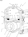
- Fig. 2a shows a pipe clamp 1 according to the invention in a first embodiment with a pipe 8 or a line or the like that has already been installed and is aligned along its longitudinal axis or pipe axis x.
- the pipe clamp 1 comprises a mounting part 2, which is used to receive the pipe 8 in a mounting space 10, a closure part 3, by means of which the mounting part 2 can be closed, and a movable and fixable locking part 4 with a hold-down 42, by means of which the pipe 8 in Mounting space 10 can be locked without play.
- the mounting part 2, the closure part 3 and the hold-down device 42 of the locking part 4 are preferably cut out of a sheet metal strip and bent, for example has a width in the range of 1 cm - 3 cm and, for example, a thickness of 1 mm - 3 mm.
- the pipe clamp 1 can therefore be manufactured with little effort.
- the mounting part 2 is C-shaped and has a head piece 21, a side piece 22 and a foot piece 23.
- the head piece 21 has a mounting opening 210 in which a mounting screw 91 is held.
- the mounting opening 210 preferably has the shape of a keyhole opening which allows the mounting screw 91 to be suspended.
- the head piece 21 On the side facing away from the side piece 22, the head piece 21 has a first coupling part 211 with a threaded bolt 212.
- a screw nut 213 is preferably placed on the threaded bolt 212.
- the permanently mounted threaded bolt 212 could also be provided with a bolt head.
- the first coupling part 211 could also be shaped into a hook.
- the threaded bolt 212 can also be missing (see Figure 4a ).
- the side piece 22 has a longitudinal slot 220 running perpendicular to the pipe axis x and a mounting opening 229 which is preferably provided.
- the assembly screw 91 can therefore also be inserted into the assembly opening 229 on the side piece 22 in order to fasten the assembly part 2 or the pipe clamp 1 laterally.
- the foot piece 23 has a downwardly pointing second coupling part 231 with a mounting bolt 232 on which a screw nut 233 is preferably provided.
- the threaded bolt 233 can also have a bolt head instead of the screw nut 233 or be completely absent (see Figure 4a ).
- the C-shaped assembly part 2 has an opening opposite the side piece 22, which can be closed by means of the rod-shaped or plate-shaped closure part 3, so that the assembly part 2 together with the closure part 3 practically forms a self-contained frame.
- the first end piece 31 of the closure part 3 is rotatably connected to the foot piece 23 of the mounting part 2 and can be connected with the second end piece 32 to the head piece 21 of the mounting part 2 in a force-fitting and / or form-fitting manner.
- the threaded bolt 233 provided on the foot piece 23 of the assembly part 2 is a hinge pin which is guided through a longitudinal opening 310 in the first end piece 31 of the closure part 3, which is rotatable in a plane that runs parallel to the pipe axis x.
- a longitudinal opening 310 is also provided, which allows what the closure part 3 not only to rotate, but also to move axially.
- the second end piece 32 of the closure part 3 is hook-shaped and is provided with a hook-shaped element 321 which is hooked into the threaded bolt 212 on the head piece 21 of the mounting part 2.
- the process of hanging and unhooking the second end piece 32 is made possible by the longitudinal opening 310, which allows the closure part 3 to be displaced in the axial direction and released from the threaded bolt 212.
- the mounting part 2 is closed by hooking in the hook 321. Furthermore, it is ensured that the load of the installed pipe 8 is partially transmitted via the closure part 3 to the head piece 21 of the assembly part 2.
- the closure part 3 also has a central part 33 with an inlet opening 300 and an adjoining longitudinal slot 330 which runs approximately along the central axis of the closure part 3.
- the inlet opening 300 is accessible from the side of the closure part 3.
- a threaded rod 45 is held displaceably in the longitudinal slot 220 of the side piece 22 of the assembly part 2 and in the longitudinal slot 330 of the closure part 3.
- the threaded rod 45 has a first guide element or threaded element 451 at the rod end that faces the closure part 3 and a second guide element or threaded element 452 at the rod end that faces the side piece 22.
- the first threaded element 451 is guided through the longitudinal slot 330 in the closure part 3 and connected to a wing nut 49.
- the second threaded element 452 is passed through the longitudinal slot 220 in the side piece 22 of the mounting part 2 and is connected to a wing nut 49.
- the threaded rod 45 together with a holding-down part 42 connected to it, forms a locking part 4, by means of which a tube 8 inserted into the assembly space 10 can be locked.
- threaded bolts 212 that are separate from one another can also be inserted into the end parts 41 of the hold-down device 42.
- the hold-down part 42 has a middle part and end parts 41 adjoining it on both sides, which are pierced and held by the threaded rod 45.
- the locking part 4 held displaceably in the guide slots 220, 330 can be displaced against the installed pipe 8 and fixed by means of the wing nuts 49. Due to the V-shape of the hold-down device 42 and the V-shape of the foot piece 23 of the assembly part 2, which point in opposite directions, tubes 8 with different diameters can be locked without play.
- Figure 2b shows the pipe clamp 1 of Fig. 2a with the locking part 3 rotated in a plane parallel to the pipe axis x against the head piece 21 of the mounting part 2 If the locking part 4 has been moved to the corresponding height position, the locking part 3 can be pushed against the head piece 21 of the mounting part 2 and against the locking part 4 or the Threaded rod 45 are displaced, the first rod end 451 of which is guided into the inlet opening 300 of the closure part 3 during this process.
- the second rod end 452 of the threaded rod 45 is preferably fixed in this process by the associated wing nut 49, which is why the locking part 4 does not have to be held while the closure part 3 is rotated.
- the longitudinal slot 220 on the side piece 22 is preferably dimensioned such that the locking part 4 can be moved to the upper stop in order to open or close the closure part 3.
- the pipe clamps 1 are delivered by the manufacturer in this position so that the closure part 3 can be opened without further manipulation and closed again after inserting a pipe 8.
- the threaded rod 45 can be displaced along the longitudinal slots 220, 330 and, by means of the wing nuts 49, for example in the FIG Fig. 2a position shown.
- the closure part 3 By tightening the wing nuts 49, the closure part 3 is fixed at the same time.
- the nuts 213, 233 on the threaded bolts 212, 232 therefore do not have to be tightened and are basically not required.
- the head piece 21 of the mounting part 2 and / or the foot piece 23 of the mounting part 2 is preferably provided with a holding element. For example, bolts with a bolt head are inserted into the head piece 21 and into the foot piece 23.
- Figure 2c shows the pipe clamp 1 of Fig. 2a with the locking part 3 turned downwards and released from the assembly part 2 and the locking part 4 moved upwards with a tube 8 inserted into the assembly space 10.
- the bolts 212, 232 preferably have a bolt head so that the locking part 3 can be rotated, but is not held axially displaceable.
- the pipe 8 is inserted and the closure part is turned upwards, as shown in FIG Figure 2b is shown.
- the locking part 4 held in the longitudinal slots 220, 330 is then guided downwards in order to lock the inserted tube 8 without play.
- the V-shaped parts of the hold-down device 42 and the foot piece 23 are provided with elastic elements 61, 62, by means of which the tube 8 is gently held and noises and vibrations are absorbed.
- Fig. 3a shows a pipe clamp 1 in a preferred embodiment with a closure part 3, which is rotatably connected with the first end piece 31 to the head piece 21 of the mounting part 2 and rotated forward with the second end piece 32, which is fork-shaped.
- Figure 3b shows the pipe clamp 1 of Fig. 3a with the locking part 3 rotated into the locking position in a plane parallel to the pipe axis x.
- the fork-shaped second end piece 32 surrounds the bolt 232 and thereby absorbs the load that is exerted by the pipe 8 on the foot piece 23 of the pipe clamp 1.
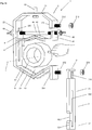
- Figure 4a shows a pipe clamp 1 in a further preferred embodiment with a closure part 3, which is rotatably connected with the first end piece 31 to the head piece 21 of the assembly part 2 and rotated with the second end piece 32 in a plane perpendicular to the pipe axis x to the right.
- the first coupling part 211 and the first end piece 31 of the closure part 3 are connected to one another by a hinge 214 or a bolt 212 aligned parallel to the pipe axis x.
- the inlet opening 300 on the closure part 3 is self-contained and designed as a keyhole opening to which the longitudinal slot 330 adjoins.
- the entry opening 300 designed as a keyhole opening is adapted to the wing nut 49, which can pass through the entry opening 300, as shown. After it has been introduced into the inlet opening 300, the threaded rod 45 can be inserted into the longitudinal slot 330 and displaced downwards with the locking part 4.
- the locking part 4 is in turn fixed at a suitable location so that the closure part 3 can be opened or closed.
- the second end piece 32 of the closure part 3 is provided with a connecting element, possibly a latching element 320, which can couple or latch onto the foot piece 23 or the second coupling part 231 provided thereon.
- the load acting on the foot piece 23 can in turn be transmitted to the closure part 3 via the downwardly pointing second coupling part 231.
- This exemplary embodiment shows, by way of example, that the first and second end pieces 31, 32 of the closure part 3 can be configured as desired in order to realize a rotary connection on the first end piece 31 or a form-fitting or force-fitting connection on the second end piece 32.
- Figure 4b shows the pipe clamp 1 of Figure 4a with the latched locking part 3 in the locked position.
- the closure part 3 can be fixed by means of the wing nut 49, so that the assembly part 2 and the closure part 3 form a closed frame that can only be opened again after the wing nut 49 has been loosened.
- the locking part 4 By operating the locking part 4, the installed pipe 8 and the closure part 3 are locked in turn.
- Fig. 5 shows the upper part of a preferably configured pipe clamp 1 with a mounting part 2, the straight head piece 21 of which is provided with a keyhole opening 210 into which the head of the mounting screw 91 can be hung.
- the keyhole opening 210 has a receiving hole 2100 with a larger diameter and an adjoining holding slot 2101 with a smaller diameter.
- Holding elements 2102 are provided between the receiving hole 2100 and the holding slot 2101.
- the mounting screw 91 pre-mounted on the ceiling can be passed through the receiving hole 2100 and inserted with the screw shaft into the holding slot 2101 at the side. During this process, the screw head is guided over the holding elements 2102, which subsequently prevent the screw head from being able to move back to the receiving hole 2100.
- Figure 6a shows a preferably configured locking part 4, which, for example, to the in Fig. 5
- the part of the assembly part 2 shown connects and has a threaded rod 45 which is rotatably held by the assembly part 2.
- the interfaces shown therefore preferably correspond to one another.
- the first end piece 31 of the closure part 3 is preferably rotatably connected to the threaded rod 45.
- the first end piece 31 is from the Pierce the threaded rod 45 and hold it between the first coupling part 211 and the rotating part 490 connected to the threaded rod 45.
- the second end piece 32 of the closure part 3 can have the configuration from Fig. 2a or Fig.
- the threaded rod 45 replaces the threaded bolt 212 from Figure 2b and is preferably arranged at this height and held on the one hand by the side piece 22 and by the first coupling part 211.
- the second end piece 32 of the closure part 3 is no longer hung on the threaded bolt 212, but on the threaded rod 45 '.
- the first coupling part 211 can again have a hook on which the closure part 3 can be hung. This hook is preferably formed in one piece on the first coupling part 211 or cut out therefrom.
- the mounting part 2 and the closure part 3 connected to it therefore also in this embodiment again form a self-contained frame via which the forces of the acting load can be transmitted.
- the threaded rod 45 has rod ends 451, 452 with opposing threads.
- the nuts 411 which are firmly connected to the end parts 41 of the hold-down device, therefore run against one another or apart when the threaded rod 45 is rotated.
- the screw nuts 411 can be integrated into the end parts 41 of the hold-down device or can be connected to them in a form-fitting manner.
- holding elements or flange elements can be provided on the end parts 41, which hold the nuts 411 in a form-fitting manner.
- the hold-down device 42 is preferably a resilient sheet metal which is optionally pretensioned. z.in Figure 6a the hold-down device 42 is therefore shown in a relaxed or tensioned position. When the threaded rod 45 is rotated, the hold-down device 42 is therefore preferably displaced or deformed into the position shown in FIG Figure 6b shown tense or relaxed position.
- Figure 6b shows the locking part 4 with the downwardly deformed hold-down device 42 from Figure 6a , the end parts 41 of which have been displaced against one another by means of the threaded rod 45.
- the threaded rod 45 is rotated manually by actuating rotating parts 490 which are firmly connected to the threaded rod 45.
- the rotating parts 490 can be in the form of wing nuts or knurled nuts, or the like.
- the locking part 4 is held firmly in this embodiment at, while the hold-down device 42 is deformable for fixing an installed pipe 8.
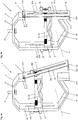
- Figure 7a shows a pipe clamp 1 according to the invention in a further preferred embodiment with a hold-down device 42, which can be optionally inserted into a slot opening 220 on the side piece 22 of the mounting part 2, and can be locked, preferably latched, in a suitable position on the closure part 3.
- the hold-down device 42 and / or the closure part 3 is designed to be elastic.
- the hold-down 42 and / or the closure part 3 is designed as a resilient plate.
- the closure part 3 which can be rotated about a bolt 212 and can preferably be fixed by a wing nut 213, is turned upwards so that a tube 8 can be inserted into the C-shaped assembly part 2.
- the connection between the closure part 3 and the assembly part 2 can also be realized by a rivet.
- the locking part 4 essentially comprises a plate-shaped hold-down device 42, which can be inserted with a first end part 411 into one of several slot openings 220 in the side piece 22 of the assembly part 2.
- a row of latching elements 339 is preferably cut out and bent out of the closure part 3, on which the second end part 412 of the plate-shaped and flexurally elastic hold-down device 42 can be latched.
- the row of locking elements 331 preferably has a sawtooth-shaped course, over which the second end part 412 of the hold-down device 42 is guided until it engages between two saw teeth. So that the shift over the ramps of the sawtooth profile is possible, the hold-down device 42 and / or the closure part 3 is designed to be resilient. After locking up to the hold-down device 42, this is therefore held in a resilient manner.
- Figure 7b shows the pipe clamp 1 of Figure 7a after the tube 8 has been inserted and the closure part 3 has been closed.
- the second end piece 32 of the closure part 3 is provided with a connecting element 320 which can at least partially enclose the foot piece 23 or the second coupling part 231 provided on it or, if necessary, engage it .
- the coupling part 231 is received by a receiving slot 23. The coupling, connecting or locking of the end piece 32 to the coupling part 231 preferably takes place automatically when the closure part 3 is rotated downward into the end position.
- Figure 7c shows the pipe clamp 1 of Figure 7b when fixing the tube 8 by means of the preferably elastic hold-down device 42. Due to the With a small raw diameter, the first end part 411 of the hold-down device 42 is positioned relatively far down in the row of the slot opening 220 on the side piece 22. The first end part 411 preferably has a tongue which is guided through one of the slot openings 220 and is preferably slightly bent so that it is held automatically. The second end part 412 of the hold-down device 42 is guided manually over the latching elements 339 until the tube 8 is fixed and the second end part 412 is held on one of the connecting elements or latching elements 339.
- the end part 412 is preferably bent upwards in the shape of a hook, so that it can engage in one of the connecting elements or latching elements 339 which are bent downwards.
Abstract
Die Rohrschelle (1) umfasst ein Montageteil (2), das der Aufnahme wenigstens eines Rohres (8) in einem Montageraum (10) dient, ein Verschlussteil (3), mittels dessen das Montageteil (2) verschliessbar ist, und ein Arretierteil (4), das einen Niederhalter (42) aufweist, mittels dessen das Rohr (8) im Montageraum (10) arretierbar ist. Erfindungsgemäss ist vorgesehen, dass das Montageteil (2) zumindest annähernd C-förmig ausgebildet ist und ein mit einem ersten Kopplungsteil (211) versehenes Kopfstück (21) und ein mit einem zweiten Kopplungsteil (231) versehenes Fussstück (23), die durch ein Seitenstück (22) miteinander verbunden sind, umfasst und dass das Verschlussteil (3) ein mit dem ersten oder zweiten Kopplungsteil (211, 231) drehbar verbundenes erstes Endstück (31) und ein mit dem zweiten oder ersten Kopplungsteil (231, 211) koppelbares zweites Endstück (32) aufweist.The pipe clamp (1) comprises a mounting part (2), which is used to hold at least one pipe (8) in an assembly space (10), a closure part (3), by means of which the mounting part (2) can be closed, and a locking part (4) ), which has a hold-down device (42), by means of which the tube (8) can be locked in the assembly space (10). According to the invention it is provided that the assembly part (2) is at least approximately C-shaped and a head piece (21) provided with a first coupling part (211) and a foot piece (23) provided with a second coupling part (231), which are connected by a side piece (22) are connected to one another, and that the closure part (3) comprises a first end piece (31) rotatably connected to the first or second coupling part (211, 231) and a second end piece which can be coupled to the second or first coupling part (231, 211) (32).
Description
Die Erfindung betrifft eine Rohrschelle für die Installation Rohren und Leitungen.The invention relates to a pipe clamp for installing pipes and lines.
Rohrschellen und Vorrichtungen zu deren Montage sind z.B. im
Rohrschellen bestehen üblicherweise aus zwei beidseitig miteinander verbindbaren Schalen, von denen die erste Schale fest montiert und die zweite Schale jeweils einseitig gelöst und weggedreht wird, um ein Rohr in die erste Schale einzulegen und anschliessend mit der zweite Schale zu fixieren, wie dies nachstehend in
Die beschriebene Rohrschelle ist zudem nur für Rohre in einem engen Bereich eines bestimmten Durchmessers einsetzbar. Sofern der Durchmesser zu gross ist, kann die Rohrschelle nur mit grossem Kraftaufwand und gleichzeitiger Deformation des installierten Rohrs geschlossen werden. Sofern der Rohrdurchmesser hingegen zu klein ist, so wird das Rohr nicht spielfrei gehalten. In diesem Fall können beim Betrieb des Rohrsystems Vibrationen und störende Geräusche auftreten. Durch stete Vibrationen können Anschlussvorrichtungen oder Verbindungsvorrichtungen gelockert werden, sodass regelmässig Wartungsarbeiten erforderlich sind.The pipe clamp described can also only be used for pipes in a narrow range of a certain diameter. If the diameter is too large, the pipe clamp can only be closed with great effort and at the same time deforming the installed pipe. If, on the other hand, the pipe diameter is too small, the pipe is not kept free of play. In this case, vibrations and annoying noises can occur during the operation of the pipe system. Connection devices or connecting devices can be loosened by constant vibrations, so that regular maintenance work is required.
Aus der
Die beschriebenen Arbeiten sind von einem Monteur, der z.B. auf einer Leiter steht, nur mit Geschick ausführbar. Das Rohr muss mit einer Hand innerhalb des Montageteils gehalten werden, während das Aufnahmeteil mit der anderen Hand mit dem Montageteil verbunden wird Zu beachten ist zudem, dass in Bauten oft schlechte Lichtverhältnisse vorherrschen, sodass das Schliessen der Rohrschelle gegebenenfalls mehrere Versuche erfordert.The work described is to be carried out by a fitter, e.g. stands on a ladder, can only be carried out with skill. The pipe must be held within the assembly part with one hand, while the receiving part is connected to the assembly part with the other hand. It should also be noted that poor lighting conditions often prevail in buildings, so that closing the pipe clamp may require several attempts.
Der vorliegenden Erfindung liegt daher die Aufgabe zugrunde, eine verbesserte Rohrschelle zu schaffen, mittels der Rohre, d.h. Leitungen aller Art, vorteilhaft installiert werden können.It is therefore an object of the present invention to provide an improved pipe clamp by means of which pipes, i. Lines of all kinds can be advantageously installed.
Insbesondere ist eine einfach aufgebaute und kostengünstige Rohrschelle zu schaffen, mit der Rohre auch unter erschwerten Installationsbedingungen einfach und schnell montierbar sind.In particular, a simply constructed and inexpensive pipe clamp is to be created with which pipes can be installed quickly and easily even under difficult installation conditions.
Der Installationsvorgang soll besonders einfach ausführbar sein. Vorzugsweise soll der Installationsvorgang in wenigen voneinander unabhängigen Installationsschritten ausführbar sein, so dass der Monteur entlastet wird und keine besonderen Sicherheitsmassnahmen erforderlich sind.The installation process should be particularly easy to carry out. The installation process should preferably be able to be carried out in a few installation steps that are independent of one another, so that the fitter is relieved and no special safety measures are required.
Der Vorgang zur Installation oder Deinstallation eines Rohres soll zudem in kürzester Zeit möglich sein.The process of installing or removing a pipe should also be possible in the shortest possible time.
Die Rohrschelle soll universell einsetzbar sein und erlauben, Rohre mit stark voneinander abweichenden Durchmessern spielfrei, stabil und materialschonend zu halten.The pipe clamp should be universally applicable and allow pipes with widely differing diameters to be kept free of play, stable and gentle on the material.
Ferner soll gewährleistet werden, dass die durch den Medientransport in den Rohren verursachte Geräuschentwicklung, unabhängig vom jeweiligen Durchmesser der installierten Rohre, minimal bleibt.Furthermore, it should be ensured that the noise generated by the media transport in the pipes remains minimal, regardless of the respective diameter of the pipes installed.
Diese Aufgabe wird mit einer Rohrschelle gelöst, welche die in Anspruch 1 angegebenen Merkmale aufweist. Vorteilhafte Ausgestaltungen der Erfindung sind in weiteren Ansprüchen angegeben.This object is achieved with a pipe clamp which has the features specified in
Die Rohrschelle umfasst ein Montageteil, das der Aufnahme wenigstens eines Rohres in einem Montageraum dient, ein Verschlussteil, mittels dessen das Montageteil verschliessbar ist, und ein Arretierteil, das einen Niederhalter aufweist, mittels dessen das Rohr im Montageraum arretierbar ist.The pipe clamp comprises a mounting part that is used to receive at least one pipe in a mounting space, a closure part, by means of which the mounting part can be closed, and a locking part, which has a hold-down device, by means of which the pipe can be locked in the mounting space.
Erfindungsgemäss ist vorgesehen, dass das Montageteil zumindest annähernd C-förmig ausgebildet ist und ein mit einem ersten Kopplungsteil versehenes Kopfstück und ein mit einem zweiten Kopplungsteil versehenes Fussstück, die durch ein Seitenstück miteinander verbunden sind, umfasst und dass das Verschlussteil ein mit dem ersten oder zweiten Kopplungsteil drehbar verbundenes erstes Endstück und ein mit dem zweiten oder ersten Kopplungsteil koppelbares zweites Endstück aufweist.According to the invention it is provided that the assembly part is at least approximately C-shaped and comprises a head piece provided with a first coupling part and a foot piece provided with a second coupling part, which are connected to one another by a side piece, and that the closure part is connected to the first or second Has coupling part rotatably connected first end piece and a second end piece which can be coupled to the second or first coupling part.
Das C-förmig ausgebildete Montageteil kann am Kopfstück oder am Seitenstück mit einem Installationskörper, z.B. der Decke oder einer Wand eines Gebäudes, einer Deckenstütze oder einem Ausleger, verbunden werden. Vorzugsweise ist am Kopfstück oder am Seitenstück eine Montageöffnung vorgesehen, durch die z.B. eine Montageschraube hindurch geführt werden kann.The C-shaped mounting part can be attached to the head piece or the side piece with an installation body, e.g. the ceiling or a wall of a building, a ceiling support or a bracket. Preferably a mounting opening is provided on the head piece or on the side piece through which e.g. a mounting screw can be passed through.
Vorzugsweise ist die Montageöffnung als Schlüssellochöffnung ausgebildet, sodass die Rohrschelle in einfacher Weise an einer Montageschraube eingehängt und fixiert werden kann. Die Schlüssellochöffnung weist ein Aufnahmeloch mit grösserem Durchmesser und einen Halteschlitz mit geringerem Durchmesser auf. Zwischen dem Aufnahmeloch und dem Halteschlitz sind vorzugsweise Halteelemente vorgesehen. Eine z.B. an einer Decke vormontierte Montageschraube kann durch das Aufnahmeloch hindurch geführt und mit dem Schraubenschaft seitlich in den Halteschlitz eingeführt werden. Bei diesem Vorgang wird der Schraubenkopf über die Halteelemente geführt, die in der Folge verhindern, dass sich der Schraubenkopf zurück zum Aufnahmeloch bewegen kann.The mounting opening is preferably designed as a keyhole opening, so that the pipe clamp can be hung and fixed in a simple manner on a mounting screw. The keyhole opening has a receiving hole with a larger diameter and a holding slot with a smaller diameter. Holding elements are preferably provided between the receiving hole and the holding slot. A mounting screw that is preassembled on a ceiling, for example, can be passed through the receiving hole and inserted with the screw shaft laterally into the holding slot. During this process, the screw head is guided over the holding elements, which then prevent the screw head from moving back to the receiving hole.
Das C-förmig ausgebildete Montageteil hat den Vorteil, dass nach der Montage der Rohrschelle ein Rohr seitlich in das Montageteil bzw. den Montageraum eingeführt und auf das Fussstück abgelegt werden kann. Der Monteur kann mit einer Hand ein Rohr in die vormontierte Rohrschelle bzw. das Montageteil einlegen und hat seine Hände anschliessend frei für weitere Tätigkeiten.The C-shaped assembly part has the advantage that after assembly of the pipe clamp, a pipe can be inserted laterally into the assembly part or the assembly space and placed on the foot piece. The fitter can insert a pipe into the preassembled pipe clamp or the assembly part with one hand and then has his hands free for further activities.
Zur Sicherung des eingelegten Rohrs wird das mit dem Montageteil verbundene Verschlussteil mit einem Handgriff in die Verschlussstellung gedreht. In der Folge kann das Arretierteil oder der Niederhalter des Arretierteils nach unten gefahren werden, um das eingelegte Rohr zu fixieren.To secure the inserted pipe, the locking part connected to the assembly part is turned into the locking position with a handle. As a result, the locking part or the hold-down device of the locking part can be moved downwards in order to fix the inserted pipe.
Der Begriff »Rohre« umfasst Rohre und Leitungen aller Art. Die erfindungsgemässe Rohrschelle erlaubt daher die Installation beliebiger Rohre bzw. Leitungen mit kleinerem oder grösserem Durchmesser, sodass Rohrschellen für unterschiedliche Durchmesser nicht mehr benötigt werden. Die installierten Rohre werden stabil und spielfrei gehalten, sodass Vibrationen der installierten Rohre und Geräuschentwicklungen weitgehend unterdrückt werden.The term “pipes” includes pipes and lines of all kinds. The pipe clamp according to the invention therefore allows any pipes or lines with a smaller or larger diameter to be installed, so that pipe clamps for different diameters are no longer required. The installed pipes are kept stable and free of play, so that vibrations of the installed pipes and noise are largely suppressed.
Die Installationsarbeiten erfolgen in voneinander unabhängigen einfachen Installationsschritten, die bequem, gegebenenfalls auch nur mit einer Hand schnell oder fast automatisch vollzogen werden können. Besonders vorteilhaft ist, dass mit nur einem Installationsschritt eine provisorische Installation des zu installierenden Rohrs möglich ist.The installation work takes place in independent, simple installation steps that can be carried out conveniently, quickly or almost automatically, if necessary with just one hand. It is particularly advantageous that a provisional installation of the pipe to be installed is possible with just one installation step.
Die verschiedenen Installationsschritte können manuell ohne Werkzeug ausgeführt werden. Das Verschlussteil kann mit einem Handgriff geöffnet werden, um das Rohr einzulegen. In der Folge kann das Verschlussteil zurückgeführt werden oder es fällt automatisch in die Ursprungslage zurück, sodass eine fast automatische Sicherung möglich ist. Das Arretierteil kann wiederum manuell nach unten gefahren und durch manuelle Betätigung von Fixierelementen, vorzugsweise Flügelmuttern, fixiert werden.The various installation steps can be carried out manually without tools. The closure part can be opened with a handle to insert the pipe. As a result, the closure part can be returned or it automatically falls back into its original position, so that an almost automatic backup is possible. The locking part can in turn be moved downwards manually and fixed by manual actuation of fixing elements, preferably wing nuts.
Die Installation eines Rohrs gelingt insbesondere auch dann einfach und sicher, wenn das Rohr an einer exponierten Lage und unter schlechten Lichtverhältnissen von einem Monteur installiert werden muss, der z.B. auf einer Leiter steht. Da die Installationsschritte getrennt voneinander ausgeführt werden können, benötigt der Installateur grundsätzlich nur eine freie Hand, um das Rohr zu installieren. Aufgrund einer klaren Trennung einfach ausführbarer Installationsschritte kann die Installation der Rohre schnell und sicher ausgeführt werden.The installation of a pipe is particularly easy and safe if the pipe has to be installed in an exposed location and under poor lighting conditions by a fitter who is standing on a ladder, for example. Since the installation steps can be carried out separately from one another, the installer basically only needs one free hand to install the pipe. Due to a clear separation of easy installation steps, the installation of the pipes can be carried out quickly and safely.
Das Arretierteil der Rohrschelle kann in unterschiedlichen Ausgestaltungen vorteilhaft realisiert werden.The locking part of the pipe clamp can advantageously be implemented in different configurations.
In einer ersten vorzugsweisen Ausgestaltung ist vorgesehen, dass das Seitenstück des Montageteils und das Verschlussteil je einen Längsschlitz aufweisen, entlang denen gegebenenfalls miteinander verbundene Führungselemente des Arretierteils verschiebbar sind, und dass das Verschlussteil eine Eintrittsöffnung aufweist, durch die hindurch das zugewandte Führungselement des Arretierteils in den Längsschlitz des Verschlussteils einführbar ist. In dieser Ausgestaltung ist das Arretierteil zusammen mit dem Niederhalter verschiebbar, um ein installiertes Rohr zu fixieren.In a first preferred embodiment it is provided that the side piece of the mounting part and the closure part each have a longitudinal slot, along which possibly interconnected guide elements of the locking part are displaceable, and that the closure part has an inlet opening through which the facing guide element of the locking part into the Longitudinal slot of the closure part is insertable. In this embodiment, the locking part can be displaced together with the hold-down device in order to fix an installed pipe.
Die Möglichkeit, das Arretierteil über eine grössere Distanz gegen das Fussstück des Montageteils zu verschieben, erlaubt die Installation von Rohren und Leitungen mit Durchmessern, die in einem weiten Bereich, gegebenenfalls um ein Mehrfaches variieren. Zum sicheren Halten der Rohre und Leitungen unterschiedlicher Durchmesser sind das Arretierteil und/oder das Fussstück des Montageteils zumindest teilweise V-förmig oder U-förmig ausgebildet.The possibility of moving the locking part over a greater distance against the base of the mounting part allows the installation of pipes and lines with diameters that vary over a wide range, possibly several times. To securely hold the pipes and lines of different diameters, the locking part and / or the foot piece of the mounting part are at least partially V-shaped or U-shaped.
In einer zweiten vorzugsweisen Ausgestaltung ist vorgesehen, dass das Arretierteil eine vom Montageteil drehbar und unverschiebbar gehaltene Gewindestange mit Stangenenden aufweist, die je durch eine Gewindeverbindung derart mit Endteilen des Niederhalters verbunden sind, dass diese bei einer Drehung der Gewindestange gegeneinander oder auseinander verschoben werden und der Niederhalter dadurch nach unten oder nach oben verschoben, ausgelenkt oder gebogen wird.In a second preferred embodiment, it is provided that the locking part has a threaded rod held rotatably and immovably by the assembly part with rod ends which are each connected to end parts of the hold-down device by a threaded connection in such a way that they are displaced against each other or apart when the threaded rod is rotated and the Hold-down is thereby shifted down or up, deflected or bent.
Die ortsfeste Montage des Arretierteils erlaubt einen sehr kompakten Aufbau der Rohrschelle.The fixed assembly of the locking part allows a very compact construction of the pipe clamp.
In einer dritten vorzugsweisen Ausgestaltung kann der Niederhalter einerseits am Montageteil oder am Verschlussteil eingehängt und andererseits am Verschlussteil oder Montageteil fixiert werden.In a third preferred embodiment, the hold-down device can be suspended on the one hand on the mounting part or on the closure part and on the other hand can be fixed on the closure part or mounting part.
Vorzugsweise ist vorgesehen, dass das Seitenstück des Montageteils wenigstens ein erstes Verbindungsteil aufweist, mit dem ein erstes Endteil des Niederhalters an einer Position oder an einer von mehreren Positionen des Seitenstücks gegebenenfalls mittels einer Rastverbindung verbindbar ist, und dass das Verschlussteil wenigstens ein zweites Verschlussteil aufweist, mit dem ein zweites Endteil des Niederhalters an einer Position oder an einer von mehreren Positionen des Verschlussteils gegebenenfalls mittels einer Rastverbindung verbindbar ist.It is preferably provided that the side piece of the assembly part has at least one first connection part, with which a first end part of the hold-down device can be connected at one position or at one of several positions of the side piece, if necessary by means of a latching connection, and that the closure part has at least one second closure part, with a second end part of the hold-down device in one position or can optionally be connected to one of several positions of the closure part by means of a latching connection.
Auf diese Weise kann die Rohrschelle einfach an unterschiedliche Rohrdurchmesser angepasst werden. Zudem kann der Niederhalter besonders einfach arretiert werden, indem das betreffende Endteilen an Verbindungsteilen vorbeigeführt wird, bis das installierte Rohr fixiert ist und dass Endteil des Niederhalters an einem Verbindungsteil arretiert ist.In this way, the pipe clamp can easily be adapted to different pipe diameters. In addition, the hold-down device can be locked particularly easily in that the end part in question is guided past connecting parts until the installed pipe is fixed and the end part of the hold-down device is locked on a connecting part.
Die Verbindungsteile können einfach in das Montageteil, insbesondere das Seitenstück, und in das Verschlussteil eingearbeitet werden. Z.B. wird am Seitenstück oder am Verschlussteil eine Reihe von schlitzförmigen Aufnahmeöffnungen vorgesehen, in die der Niederhalter wahlweise eingesetzt werden kann. Aus dem Verschlussteil oder dem Seitenstück können ferner Rastelemente ausgeschnitten und ausgebogen werden, über die das betreffende Endteil geführt wird, bis es einrastet.The connecting parts can easily be incorporated into the assembly part, in particular the side piece, and into the closure part. E.g. a series of slot-shaped receiving openings is provided on the side piece or on the closure part, into which the hold-down device can be optionally inserted. Furthermore, locking elements can be cut out and bent out of the closure part or the side piece, over which the relevant end part is guided until it engages.
In allen beschriebenen Ausgestaltungen werden das Arretierteil und/oder das Fussstück des Montageteils vorzugsweise elastisch ausgebildet und/oder mit elastischen Elementen z.B. aus Kunststoff oder Gummi versehen, welche gewährleisten, dass die installierten Rohre spielfrei und schonend gehalten werden. Schwingungen und Geräusche der installierten Rohre werden gedämpft, sodass störende Emissionen vermieden werden.In all the embodiments described, the locking part and / or the foot piece of the mounting part are preferably designed to be elastic and / or with elastic elements, e.g. made of plastic or rubber, which ensure that the installed pipes are held gently and without play. Vibrations and noises in the installed pipes are dampened so that disruptive emissions are avoided.
Vorteilhaft ist ferner, dass die Elemente der Rohrschelle kostengünstig gefertigt und in einfacher Weise zusammengebaut werden können. Das Montageteil, das Verschlussteil und das Arretierteil können aus einem Blechstück bzw. einem Blechstreifen gebogen werden. Vorzugsweise werden die genannten Teile, insbesondere das Montageteil und/oder das Verschlussteil durch Verformungen versteift, sodass auch schwere Rohre vom Montageteil sicher gehalten werden können.It is also advantageous that the elements of the pipe clamp can be manufactured inexpensively and assembled in a simple manner. The assembly part, the closure part and the locking part can be bent from a piece of sheet metal or a sheet metal strip. The parts mentioned, in particular the assembly part and / or the closure part, are preferably stiffened by deformations, so that even heavy pipes can be securely held by the assembly part.
Das C-förmige Montageteil kann durch Zusammenfügen von zwei L-förmigen Montageteilelementen, von denen eines das Kopfstück und das andere das Fussstück des Montageteils bildet, gefertigt werden. Die mit einfachen Maschinen gefertigten Montageteilelemente können z.B. durch Toxen, Schrauben oder Schweissen miteinander verbunden werden.The C-shaped assembly part can be manufactured by joining two L-shaped assembly part elements, one of which forms the head piece and the other forms the foot piece of the assembly part. The sub-assembly elements produced with simple machines can e.g. be connected to each other by toxin, screwing or welding.
Die Führungselemente des Arretierteils, die in den Längsschlitzen des Verschlussteils und des Seitenstücks des Montageteils geführt sind, sind vorzugsweise separate Schrauben, Schraubenelemente, Gewindebolzen oder Stangenenden einer Gewindestange, die je mit einem Gewinde versehen sind. Die Schrauben, Schraubenelemente oder Stangenenden der Gewindestange sind mit Schraubenmuttern, vorzugsweise Flügelschrauben versehen, die manuell festgezogen werden können. Das Arretierteil kann daher beidseitig mit Schraubenelementen, Gewindebolzen oder dergleichen oder mit einer durchgehenden Gewindestange versehen sein, von der eine Niederhalter gehalten wird. Die Verwendung einer Gewindestange verleiht der Rohrschelle eine höhere Stabilität und gleichzeitig eine höhere Flexibilität. Die Gewindestange kann in einfacher Weise durch Öffnungen in den Endteilen des Niederhalters hindurch geschoben werden.The guide elements of the locking part, which are guided in the longitudinal slots of the closure part and of the side part of the mounting part, are preferably separate screws, screw elements, threaded bolts or rod ends of a threaded rod, each of which is provided with a thread. The screws, screw elements or rod ends of the threaded rod are provided with screw nuts, preferably wing screws, which can be tightened manually. The locking part can therefore be provided on both sides with screw elements, threaded bolts or the like or with a continuous threaded rod by which a hold-down device is held. The use of a threaded rod gives the pipe clamp greater stability and, at the same time, greater flexibility. The threaded rod can easily be pushed through openings in the end parts of the hold-down device.
Das dem Verschlussteil zugewandte Führungselement kann in den Längsschlitz im Verschlussteil eingeführt werden, wenn dieses in die Verschlussstellung gedreht wird. Dazu weist das Verschlussteil eine Eintrittsöffnung auf, die in sich geschlossen oder zur Seite hin geöffnet ist.The guide element facing the closure part can be inserted into the longitudinal slot in the closure part when the latter is rotated into the closed position. For this purpose, the closure part has an inlet opening which is closed in itself or opened to the side.
In einer bevorzugten Ausgestaltung weist die in sich geschlossene Eintrittsöffnung eine an das Fixierelement, gegebenenfalls die Flügelmutter, angepasste Form auf, die es erlaubt, das Fixierelement durch die Eintrittsöffnung hindurch zu führen. Vorzugsweise ist die Eintrittsöffnung eine Schlüssellochöffnung, die es erlaubt, das Führungselement mit dem Fixierelement, gegebenenfalls der Flügelmutter, hindurch führen, und anschliessend in den an die Eintrittsöffnung anschliessenden Längsschlitz einzuführen. Eine in sich geschlossene Eintrittsöffnung, die praktisch zu keiner Schwächung des Verschlussteils führt, wird vorzugsweise verwendet, wenn das Verschlussteil frontal gegen das Führungselement geführt wird, sodass das Führungselement, z.B. der Gewindebolzen oder die Gewindestange, axial durch die Eintrittsöffnung hindurch treten kann.In a preferred embodiment, the self-contained inlet opening has a shape adapted to the fixing element, possibly the wing nut, which allows the fixing element to be guided through the inlet opening. The inlet opening is preferably a keyhole opening which allows the guide element with the fixing element, optionally the wing nut, to be guided through and then to be introduced into the longitudinal slot adjoining the inlet opening. A closed entry opening which practically does not lead to any weakening of the closure part is preferably used when the closure part is guided frontally against the guide element so that the guide element, e.g. the threaded bolt or the threaded rod can pass axially through the inlet opening.
In weiteren vorzugsweisen Ausgestaltungen ist das Verschlussteil seitlich gegen das Führungselement drehbar. In diesen Ausgestaltungen ist die Eintrittsöffnung zur Seite des Verschlussteils hin geöffnet. Das Führungselement, z.B. der Gewindebolzen oder Gewindestange, kann dadurch seitlich in die Eintrittsöffnung und dann geneigt oder senkrecht dazu in den Längsschlitz im Verschlussteil eingeführt werden.In further preferred configurations, the closure part can be rotated laterally against the guide element. In these configurations, the inlet opening is open to the side of the closure part. The guide element, e.g. the threaded bolt or threaded rod can thereby be inserted laterally into the inlet opening and then inclined or perpendicular to it into the longitudinal slot in the closure part.
Vorzugsweise ist vorgesehen, dass der obere Anschlag des Längsschlitzes im Seitenstück derart gewählt ist, dass das Arretierteil an diesem Anschlag mit dem betreffenden Führungselement derart gehalten ist, dass dieses bei einer Drehung des Verschlussteils automatisch in die Eintrittsöffnung eintritt. Die Rohrschelle wird vorzugsweise mit einem entsprechend positionierten und fixierten Arretierteil ausgeliefert, sodass keine weiteren Vorbereitungen zur Installation erforderlich sind.It is preferably provided that the upper stop of the longitudinal slot in the side piece is chosen such that the locking part is held on this stop with the relevant guide element in such a way that it automatically enters the inlet opening when the closure part is rotated. The pipe clamp is preferably with a corresponding positioned and fixed locking part, so that no further preparations for installation are required.
In vorzugsweisen Ausgestaltungen weist das erste Endstück des Verschlussteils eine Längsöffnung auf, in der das bolzenförmige erste oder zweite Kopplungsteil des Montageteils derart gehalten ist, dass das Verschlussteil axial verschiebbar ist. Das Verschlussteil kann daher nicht nur gedreht sondern auch axial verschoben werden, um das zweite Endstück des Verschlussteils mit dem zweiten oder ersten Kopplungsteil des Montageteils zu verbinden.In preferred embodiments, the first end piece of the closure part has a longitudinal opening in which the bolt-shaped first or second coupling part of the assembly part is held in such a way that the closure part is axially displaceable. The closure part can therefore not only be rotated but also displaced axially in order to connect the second end piece of the closure part to the second or first coupling part of the mounting part.
Das zweite Endstück des Verschlussteils ist vorzugsweise hakenförmig, bolzenförmig oder gabelförmig ausgebildet und mit dem zugeordneten ersten oder zweiten Kopplungsteil des Montageteils vorzugsweise kraftschlüssig oder formschlüssig verbindbar. Nach der formschlüssigen oder kraftschlüssigen Verbindung des Verschlussteils mit dem ersten oder zweiten Kopplungsteil kann die auf das Fussstück des Montageteils Montageteil einwirkende Last in das Verschlussteil eingeleitet und auf dieser Seite zum Kopfstück des Montageteils übertragen werden. Das Montageteil bildet mit dem Verschlussstück daher vorzugsweise einen in sich geschlossenen Rahmen, der das installierte Rohr einschliesst und dessen Last optimal aufnimmt.The second end piece of the closure part is preferably hook-shaped, bolt-shaped or fork-shaped and can be connected to the associated first or second coupling part of the mounting part, preferably in a force-fitting or form-fitting manner. After the locking part has been positively or non-positively connected to the first or second coupling part, the load acting on the foot of the mounting part mounting part can be introduced into the locking part and transferred on this side to the head part of the mounting part. The assembly part with the closure piece therefore preferably forms a self-contained frame which encloses the installed pipe and optimally absorbs its load.
Besonders vorteilhaft ist, dass nach der Fixierung des Arretierteils das Verschlussteil in der Verschlussstellung arretiert ist. Durch das Arretierteil wird daher einerseits das installierte Rohr und andererseits das Verschlussteil arretiert.It is particularly advantageous that after the locking part has been fixed, the locking part is locked in the locking position. The installed pipe on the one hand and the closure part on the other hand are therefore locked by the locking part.
Die Teile der Rohrschelle, das Montageteil, das Verschlussteil und das Arretierteil, spielen daher vorteilhaft zusammen, sodass verschiedene synergistische Effekte resultieren. Das Montageteil stellt wesentliche Funktionen zum Halten des installierten Rohres bereit und muss lediglich verschlossen werden. Das Verschlussteil, das zum Verschliessen des Montageteils dient, stellt gleichzeitig einen Längsschlitz zur Führung des Arretierteils zur Verfügung und das Arretierteil kann vorteilhaft zur Arretierung des Verschlussteils verwendet werden. Durch diese synergistischen Funktionen können mit einer einfachen Struktur der Rohrschelle zahlreiche weitere Vorteile realisiert werden. Aufgrund der Realisierung mehrerer Funktionen resultiert eine besonders einfache Ausgestaltung der Rohrschelle mit nur wenigen Vorrichtungsteilen.The parts of the pipe clamp, the assembly part, the closure part and the locking part therefore interact advantageously, so that different synergistic effects result. The mounting part provides essential functions for holding the installed pipe and only needs to be closed. The closure part, which is used to close the assembly part, at the same time provides a longitudinal slot for guiding the locking part and the locking part can advantageously be used to lock the closure part. Due to these synergistic functions, numerous other advantages can be realized with a simple structure of the pipe clamp. The realization of several functions results in a particularly simple design of the pipe clamp with only a few device parts.
In vorzugsweisen Ausgestaltungen sind das erste Kopplungsteil und/oder das zweite Kopplungsteil und/oder das erste und/oder zweite Endstück des Verschlussteils mit Gelenkelementen und/oder Scharnierelementen und/oder Blockierelementen und/oder Rastelementen versehen. Das zweite Endstück des Verschlussteils ist vorzugsweise mit einem elastischen Rastelement versehen, welches am zugewandten Kopfstück oder Fussstück des Montageteils Einrasten kann. Das erste Endstück und das zugewandte Kopfstück oder Fussstück des Montageteils weisen vorzugsweise zueinander korrespondierende Gelenkelemente oder Scharnierelemente auf, die, gegebenenfalls nach Verbindung mit einem Bolzen, ein Gelenk bilden.In preferred embodiments, the first coupling part and / or the second coupling part and / or the first and / or second end piece of the Closure part provided with joint elements and / or hinge elements and / or blocking elements and / or locking elements. The second end piece of the closure part is preferably provided with an elastic latching element which can latch onto the facing head piece or foot piece of the mounting part. The first end piece and the facing head piece or foot piece of the assembly part preferably have joint elements or hinge elements which correspond to one another and which, optionally after being connected to a bolt, form a joint.
Nachfolgend wird die Erfindung anhand von Zeichnungen näher erläutert. Dabei zeigt:
- Fig. 1a
- die eingangs beschriebene bekannte Rohrschelle 7 in verschlossenem Zustand;
- Fig. 1b
- die
bekannte Rohrschelle 7 vonFig. 1a während derInstallation eines Rohres 8; - Fig. 2a
- eine erfindungsgemässe Rohrschelle 1 in einer ersten Ausgestaltung mit einem C-förmig ausgebildeten Montageteil 2,
das ein Kopfstück 21,ein Seitenstück 22und ein Fussstück 23 aufweist, und dasdurch ein Verschlussteil 3 abschliessbar ist, dessen erstes Endstück 31 drehbarmit dem Fussstück 23 verbunden ist, undmit einem Arretierteil 4, welches inLängsschlitzen Montageteils 2 und des Seitenstücks 22 verschiebbar gehalten und gegen ein installiertesRohr 8 geführt ist, welches entlang einer Rohrachse x ausgerichtet ist; - Fig. 2b
- die
Rohrschelle 1 vonFig. 2a mit dem in einer Ebene parallel zur Rohrachse xgegen das Kopfstück 21 desMontageteils 2gedrehten Verschlussteil 3; - Fig. 2c
- die
Rohrschelle 1 vonFig. 2a mit dem nach unten gedrehten und vom Montageteil 2gelösten Verschlussteil 3 sowie dem nach oben gefahrenen Arretierteil 4 mit einem inden Montageraum 10eingeführten Rohr 8; - Fig. 3a
eine Rohrschelle 1 in einer vorzugsweisen Ausgestaltungmit einem Verschlussteil 3, welches mit dem ersten Endstück 31 drehbarmit dem Kopfstück 21 desMontageteils 2 verbunden und mit dem zweiten Endstück 32 nach vorn gedreht ist;- Fig. 3b
- die
Rohrschelle 1 vonFig. 3a mit dem in einer Ebene parallel zur Rohrachse x in dieVerschlussstellung gedrehten Verschlussteil 3; - Fig. 4a
eine Rohrschelle 1 in einer weiteren vorzugsweisen Ausgestaltungmit einem Verschlussteil 3, welches mit dem ersten Endstück 31 drehbarmit dem Kopfstück 21 desMontageteils 2 verbunden und mit dem zweiten Endstück 32 in einer Ebene senkrecht zur Rohrachse x nach rechts gedreht ist;- Fig. 4b
- die
Rohrschelle 1 vonFig. 4a mitdem eingerasteten Verschlussteil 3 in Verschlussstellung; - Fig. 5
- den oberen Teil einer vorzugsweise ausgestalteten Rohrschelle 1
mit einem Montageteil 2,dessen Kopfstück 21 mit einerSchlüssellochöffnung 210 versehen ist; - Fig. 6a
- ein vorzugsweise ausgestaltetes Arretierteil 4, welches z.B. an den in
Fig. 5 gezeigten Teil des Montageteils 2 anschliesst und eine Gewindestange 45 aufweist, dievom Montageteil 2 drehbar gehalten ist; - Fig. 6b
das Arretierteil 4 mit dem nach unten gedrückten Niederhalter 42 vonFig. 6a ,dessen Endteile 41 durch Drehung der Gewindestange 45 gegeneinander verschoben wurden;- Fig. 7a
- eine erfindungsgemässe Rohrschelle 1 in einer weiteren vorzugsweisen Ausgestaltung mit einem vorzugsweise elastischen Niederhalter 42, der am
Seitenstück 22 desMontageteils 2 wahlweise ineine Schlitzöffnung 220 eingesetzt,und am Verschlussteil 3 an einer passenden Position eingerastet werden kann; - Fig. 7b
- die
Rohrschelle 1 vonFig. 7a nach dem Einsetzen desRohrs 8 und dem Verschliessen desVerschlussteils 3; und - Fig. 7c
- die
Rohrschelle 1 vonFig. 7b beim Fixieren desRohrs 8 mittels des elastischen Niederhalters 42.
- Fig. 1a
- the known
pipe clamp 7 described above in the closed state; - Figure 1b
- the well-known
pipe clamp 7 ofFig. 1a during the installation of apipe 8; - Fig. 2a
- a
pipe clamp 1 according to the invention in a first embodiment with a C-shapedassembly part 2, which has ahead piece 21, aside piece 22 and afoot piece 23, and which can be locked by aclosure part 3, thefirst end piece 31 of which is rotatably connected to thefoot piece 23 is, and with a lockingpart 4, which is held displaceably inlongitudinal slots part 2 and theside piece 22 and is guided against an installedpipe 8 which is aligned along a pipe axis x; - Figure 2b
- the
pipe clamp 1 ofFig. 2a with theclosure part 3 rotated in a plane parallel to the pipe axis x against thehead piece 21 of the mountingpart 2; - Figure 2c
- the
pipe clamp 1 ofFig. 2a with theclosure part 3 rotated downwards and released from theassembly part 2 and with the lockingpart 4 moved upwards with atube 8 inserted into theassembly space 10; - Fig. 3a
- a
pipe clamp 1 in a preferred embodiment with aclosure part 3, which is rotatably connected with thefirst end piece 31 to thehead piece 21 of the mountingpart 2 and is rotated forward with thesecond end piece 32; - Figure 3b
- the
pipe clamp 1 ofFig. 3a with theclosure part 3 rotated into the closed position in a plane parallel to the tube axis x; - Figure 4a
- a
pipe clamp 1 in a further preferred embodiment with aclosure part 3 which is rotatably connected with thefirst end piece 31 to thehead piece 21 of the mountingpart 2 and rotated with thesecond end piece 32 in a plane perpendicular to the pipe axis x to the right; - Figure 4b
- the
pipe clamp 1 ofFigure 4a with the latched lockingpart 3 in the locked position; - Fig. 5
- the upper part of a preferably configured
pipe clamp 1 with a mountingpart 2, thehead piece 21 of which is provided with akeyhole opening 210; - Figure 6a
- a preferably configured locking
part 4, which, for example, to the inFig. 5 the shown part of the mountingpart 2 connects and has a threadedrod 45 which is rotatably held by the mountingpart 2; - Figure 6b
- the locking
part 4 with the pressed downholder 42 ofFigure 6a , theend parts 41 of which have been displaced against each other by rotating the threadedrod 45; - Figure 7a
- a
pipe clamp 1 according to the invention in a further preferred embodiment with a preferably elastic hold-downdevice 42, which can be optionally inserted into aslot opening 220 on theside piece 22 of the mountingpart 2, and can be snapped into a suitable position on theclosure part 3; - Figure 7b
- the
pipe clamp 1 ofFigure 7a after inserting thetube 8 and closing theclosure part 3; and - Figure 7c
- the
pipe clamp 1 ofFigure 7b when fixing thepipe 8 by means of the elastic hold-downdevice 42.
Das Montageteil 2 ist C-förmig ausgebildet und weist ein Kopfstück 21, ein Seitenstück 22 und ein Fussstück 23 auf. Das Kopfstück 21 weist eine Montageöffnung 210 auf, in der eine Montageschraube 91 gehalten ist. Die Montageöffnung 210 weist vorzugsweise die Form einer Schlüssellochöffnung auf, die es erlaubt, die Montageschraube 91 einzuhängen.The mounting
Auf der dem Seitenstück 22 abgewandten Seite weist das Kopfstück 21 ein erstes Kopplungsteil 211 mit einem Gewindebolzen 212 auf. Auf den Gewindebolzen 212 ist vorzugsweise eine Schraubenmutter 213 aufgesetzt. Der fest montierte Gewindebolzen 212 könnte auch mit einem Bolzenkopf versehen sein. Alternativ könnte das erste Kopplungsteil 211 auch zu einem Haken geformt sein. Der Gewindebolzen 212 kann auch fehlen (siehe
Das Seitenstück 22 weist einen senkrecht zur Rohrachse x verlaufenden Längsschlitz 220 und eine vorzugsweise vorgesehene Montageöffnung 229 auf. Die Montageschraube 91 kann daher auch in Montageöffnung 229 am Seitenstück 22 eingesetzt werden, um das Montageteil 2 bzw. die Rohrschelle 1 seitlich zu befestigen.The
Das Fussstück 23 weist ein nach unten weisendes zweites Kopplungsteil 231 mit einem Montagebolzen 232 auf, an dem vorzugsweise eine Schraubenmutter 233 vorgesehen ist. Der Gewindebolzen 233 kann ferner anstelle der Schraubenmutter 233 einen Bolzenkopf aufweisen oder vollständig fehlen (siehe
Das C-förmig ausgebildete Montageteil 2 weist eine dem Seitenstück 22 gegenüberliegende Öffnung auf, die mittels des stabförmigen oder plattenförmigen Verschlussteils 3 abschliessbar ist, sodass das Montageteil 2 zusammen mit dem Verschlussteil 3 praktisch einen in sich geschlossenen Rahmen bildet. Das erste Endstück 31 des Verschlussteils 3 ist dazu mit dem Fussstück 23 des Montageteils 2 drehbar verbunden und mit dem zweiten Endstück 32 mit dem Kopfstück 21 des Montageteils 2 kraftschlüssig und/oder formschlüssig verbindbar. Nach dem Verschliessen der Rohrschelle 1 werden die einwirkenden Kräfte zu gleichen Teilen über den Rahmen bzw. das Seitenstück 22 des Montageteils 2 und das Verschlussteil 3 zum Kopfstück 21 des Montageteils 2 übertragen.The C-shaped
Der am Fussstück 23 des Montageteils 2 vorgesehene Gewindebolzen 233 ist ein Gelenkbolzen, der durch eine Längsöffnung 310 im ersten Endstück 31 des Verschlussteils 3 geführt ist, das in einer Ebene drehbar ist, die parallel zur Rohrachse x verläuft. Im ersten Endstück 31 des Verschlussteils 3 ist zudem eine Längsöffnung 310 vorgesehen, die es erlaubt, was Verschlussteil 3 nicht nur zu drehen, sondern auch axial zu verschieben.The threaded
Das zweite Endstück 32 des Verschlussteils 3 ist hakenförmig ausgebildet und mit einem hakenförmigen Element 321 versehen, das in den Gewindebolzen 212 am Kopfstück 21 des Montageteils 2 eingehängt ist. Der Vorgang des Einhängens und Aushängens des zweiten Endstücks 32 wird durch die Längsöffnung 310 ermöglicht, die es erlaubt, das Verschlussteil 3 in axialer Richtung zu verschieben und vom Gewindebolzen 212 zu lösen. Durch das Einhängen des Hakens 321 wird das Montageteil 2 verschlossen. Ferner wird sichergestellt, dass die Last des installierten Rohres 8 anteilsweise über das Verschlussteil 3 zum Kopfstück 21 des Montageteils 2 übertragen wird.The
Das Verschlussteil 3 weist zudem ein Mittelteil 33 mit einer Eintrittsöffnung 300 und einem daran anschliessenden Längsschlitz 330 auf, der etwa entlang der Mittelachse des Verschlussteils 3 verläuft. Die Eintrittsöffnung 300 ist von der Seite des Verschlussteils 3 her zugänglich.The
Im Längsschlitz 220 des Seitenstücks 22 des Montageteils 2 und im Längsschlitz 330 des Verschlussteils 3 ist eine Gewindestange 45 verschiebbar gehalten. Die Gewindestange 45 weist am Stangenende, das dem Verschlussteil 3 zugewandt ist, ein erstes Führungselement bzw. Gewindeelement 451 und am Stangenende, das dem Seitenstück 22 zugewandt ist, ein zweites Führungselement bzw. Gewindeelement 452 auf. Das erste Gewindeelement 451 ist durch den Längsschlitz 330 im Verschlussteil 3 hindurch geführt und mit einer Flügelmutter 49 verbunden. Das zweite Gewindeelement 452 ist durch den Längsschlitz 220 im Seitenstück 22 des Montageteils 2 hindurch geführt und mit einer Flügelmutter 49 verbunden. Die Gewindestange 45 bildet zusammen mit einem damit verbundenen Niederhalteteil 42 ein Arretierteil 4, mittels dessen ein in den Montageraum 10 eingesetztes Rohr 8 arretierbar ist.A threaded
Anstelle einer durchgehenden Gewindestange 45 können auch voneinander getrennte Gewindebolzen 212 in die Endteile 41 des Niederhalters 42 eingesetzt werden.Instead of a continuous threaded
Das Niederhalteteil 42 weist ein Mittelteil und beidseits daran anschliessende Endteile 41 auf, die von der Gewindestange 45 durchstossen und gehalten sind.The hold-down
Das in den Führungsschlitzen 220, 330 verschiebbar gehaltene Arretierteil 4 kann gegen das installierte Rohr 8 verschoben und mittels der Flügelmuttern 49 fixiert werden. Durch die V-Form des Niederhalters 42 und die V-Form des Fussstücks 23 des Montageteils 2, die in entgegengesetzte Richtungen weisen, können Rohre 8 mit unterschiedlichen Durchmessern spielfrei arretiert werden.The locking
Vorzugsweise ist der Längsschlitz 220 am Seitenstück 22 derart dimensioniert, dass das Arretierteil 4 zum oberen Anschlag gefahren werden kann, um das Verschlussteil 3 zu öffnen oder zu verschliessen. Z.B. werden die Rohrschellen 1 vom Hersteller in dieser Stellung ausgeliefert, sodass das Verschlussteil 3 ohne weitere Manipulationen geöffnet und nach Einlegen eines Rohrs 8 wieder verschlossen werden kann.The
Nachdem die Gewindestange 45 bzw. das Gewindeelement 451 in die Eintrittsöffnung 300 eingeführt wurde, kann die Gewindestange 45 entlang den Längsschlitzen 220, 330 verschoben und mittels der Flügelmuttern 49 z.B. in der in
Durch das Anziehen der Flügelmuttern 49 wird gleichzeitig das Verschlussteil 3 fixiert. Die Schraubenmuttern 213, 233 an den Gewindebolzen 212, 232 müssen daher nicht festgezogen werden und werden grundsätzlich nicht benötigt. Zur Sicherung des Verschlussteils 3 nach dem Lösen der Flügelmuttern 49 ist das Kopfstück 21 des Montageteils 2 und/oder das Fussstück 23 des Montageteils 2 vorzugsweise mit einem Halteelement versehen. z.B. sind Bolzen mit einem Bolzenkopf in das Kopfstück 21 und in das Fussstück 23 eingesetzt.By tightening the
Die Eintrittsöffnung 300 am Verschlussteil 3 ist in sich geschlossen und als Schlüssellochöffnung ausgebildet, an die der Längsschlitz 330 anschliesst. Die als Schlüssellochöffnung ausbildete Eintrittsöffnung 300 ist an die Flügelmutter 49 angepasst, die durch die Eintrittsöffnung 300 hindurch treten kann, wie dies gezeigt ist. Nach Einführung in die Eintrittsöffnung 300 kann die Gewindestange 45 in den Längsschlitz 330 eingeführt und mit dem Arretierteil 4 nach unten verschoben werden.The
Das Arretierteil 4 wird wiederum an passender Stelle fixiert, sodass das Verschlussteil 3 geöffnet oder geschlossen werden kann.The locking
Das zweite Endstück 32 des Verschlussteils 3 ist mit einem Verbindungselements, gegebenenfalls Rastelement 320 versehen, welches am Fussstück 23 bzw. an dem daran vorgesehenen zweiten Kopplungsteil 231 ankoppeln bzw. einrasten kann. Die auf das Fussstück 23 einwirkende Last kann wiederum über das nach unten weisende zweite Kopplungsteil 231 auf das Verschlussteil 3 übertragen werden. Dieses Ausführungsbeispiel zeigt exemplarisch, dass das erste und zweite Endstück 31, 32 des Verschlussteils 3 beliebig ausgestaltet werden können, um eine Drehverbindung am ersten Endstück 31 bzw. eine formschlüssige oder kraftschlüssige Verbindung am zweiten Endstück 32 zu realisieren.The
Auch in dieser Ausgestaltung kann das Verschlussteil 3 mittels der Flügelmutter 49 fixiert werden, so das das Montageteil 2 und das Verschlussteil 3 einen geschlossenen Rahmen bilden, der erst nach Lösen der Flügelmutter 49 wieder geöffnet werden kann. Durch Bedienung des Arretierteils 4 werden somit wiederum das installierte Rohr 8 und das Verschlussteil 3 arretiert.In this embodiment, too, the
Die Schlüssellochöffnung 210 weist ein Aufnahmeloch 2100 mit grösserem Durchmesser und einen daran anschliessenden Halteschlitz 2101 mit geringerem Durchmesser auf. Zwischen dem Aufnahmeloch 2100 und dem Halteschlitz 2101 sind Halteelemente 2102 vorgesehen. Die an der Decke vormontierte Montageschraube 91 kann durch das Aufnahmeloch 2100 hindurch geführt und mit dem Schraubenschaft seitlich in den Halteschlitz 2101 eingeführt werden. Bei diesem Vorgang wird der Schraubenkopf über die Halteelemente 2102 geführt, die in der Folge verhindern, dass sich der Schraubenkopf zurück zum Aufnahmeloch 2100 bewegen kann.The
Die Gewindestange 45 weist Stangenenden 451, 452 mit gegenläufigen Gewinden auf. Die Schraubenmuttern 411, die fest mit den Endteilen 41 des Niederhalters verbunden sind, laufen bei einer Drehung der Gewindestange 45 daher gegeneinander oder auseinander. Die Schraubenmuttern 411 können in die Endteilen 41 des Niederhalters integriert oder formschlüssig damit verbindbar sein. Dazu können an den Endteilen 41 z.B. Halteelemente oder Flanschelemente vorgesehen sein, die die Schraubenmuttern 411 formschlüssig halten. Der Niederhalter 42 ist vorzugsweise ein federelastisches Blech, welches gegebenenfalls vorgespannt ist. z.in
Das Arretierteil 4 ist in dieser Ausgestaltung bei fest gehalten, während der Niederhalter 42 zur Fixierung eines installierten Rohres 8 deformierbar ist.The locking
Das Verschlussteil 3, welches um einen Bolzen 212 drehbar und vorzugsweise durch eine Flügelmutter 213 fixierbar ist, ist nach oben gedreht, sodass ein Rohr 8 in das C-förmige Montageteil 2 eingelegt werden kann. Die Verbindung zwischen dem Verschlussteil 3 und dem Montageteil 2 kann auch durch eine Niete realisiert werden.The
Das Arretierteil 4 umfasst im wesentlichen einen plattenförmigen Niederhalter 42, welcher mit einem ersten Endteil 411 in eine von mehreren Schlitzöffnungen 220 im Seitenstück 22 des Montageteils 2 einsetzbar ist.The locking
Aus dem Verschlussteil 3 ist vorzugsweise eine Reihe von Rastelementen 339 ausgeschnitten und ausgebogen, an denen das zweite Endteil 412 des plattenförmigen und biegeelastischen Niederhalters 42 eingerastet werden kann. Die Reihe der Rastelemente 331 weist vorzugsweise einen Sägezahnförmigen Verlauf auf, über den das zweite Endteil 412 des Niederhalters 42 geführt wird, bis es zwischen zwei Sägezähnen einrastet. Damit die Verschiebung über die Rampen des Sägezahnverlaufs möglich ist, ist der Niederhalter 42 und/oder das Verschlussteil 3 federelastisch ausgebildet. Nach dem Einrasten bis Niederhalters 42 ist dieser daher federelastisch gehalten.A row of latching
Claims (15)
dass das Verschlussteil (3) mit dem ersten Endstück (31) in einer Ebene, die zumindest annähernd senkrecht zu einer Montageachse (x) eines im Aufnahmeraum (10) gehaltenen Rohres (8) verläuft, derart drehbar mit dem Montageteil (2) verbunden ist, dass das zugewandte Führungselement (45, 451) des Arretierteils (4) zumindest annähernd senkrecht in die Eintrittsöffnung (300) eintreten kann, oder
dass das Verschlussteil (3) mit dem ersten Endstück (31) in einer Ebene drehbar mit dem Montageteil (2) verbunden ist, sodass das zugewandte Führungselement (45, 451) des Arretierteils (4) seitlich in die Eintrittsöffnung (300) eintreten kann.Pipe clamp (1) according to one of claims 4 - 7, characterized in that
that the closure part (3) with the first end piece (31) in a plane which runs at least approximately perpendicular to an assembly axis (x) of a tube (8) held in the receiving space (10) is rotatably connected to the assembly part (2) that the facing guide element (45, 451) of the locking part (4) can enter the inlet opening (300) at least approximately perpendicularly, or
that the closure part (3) with the first end piece (31) is rotatably connected in one plane to the mounting part (2) so that the facing guide element (45, 451) of the locking part (4) can enter the inlet opening (300) from the side.
Applications Claiming Priority (1)
| Application Number | Priority Date | Filing Date | Title |
|---|---|---|---|
| EP19159646 | 2019-02-27 |
Publications (1)
| Publication Number | Publication Date |
|---|---|
| EP3702652A1 true EP3702652A1 (en) | 2020-09-02 |
Family
ID=65628635
Family Applications (1)
| Application Number | Title | Priority Date | Filing Date |
|---|---|---|---|
| EP19184032.1A Withdrawn EP3702652A1 (en) | 2019-02-27 | 2019-07-02 | Pipe clamp |
Country Status (1)
| Country | Link |
|---|---|
| EP (1) | EP3702652A1 (en) |
Cited By (2)
| Publication number | Priority date | Publication date | Assignee | Title |
|---|---|---|---|---|
| US11333181B2 (en) * | 2020-07-09 | 2022-05-17 | ASC Engineered Solutions, LLC | Stiffening system for hanger assembly |
| US20230268726A1 (en) * | 2022-02-22 | 2023-08-24 | Ford Global Technologies, Llc | Wiring clip for vehicle electronics |
Citations (3)
| Publication number | Priority date | Publication date | Assignee | Title |
|---|---|---|---|---|
| EP2112413A1 (en) * | 2008-04-25 | 2009-10-28 | Zurecon AG | Pipe clamp |
| EP2322830A1 (en) * | 2009-11-13 | 2011-05-18 | Zurecon Ag | Multifunctional pipe clamp |
| EP2325539A1 (en) | 2009-11-13 | 2011-05-25 | Zurecon AG | Multifunctional pipe clamp |
-
2019
- 2019-07-02 EP EP19184032.1A patent/EP3702652A1/en not_active Withdrawn
Patent Citations (3)
| Publication number | Priority date | Publication date | Assignee | Title |
|---|---|---|---|---|
| EP2112413A1 (en) * | 2008-04-25 | 2009-10-28 | Zurecon AG | Pipe clamp |
| EP2322830A1 (en) * | 2009-11-13 | 2011-05-18 | Zurecon Ag | Multifunctional pipe clamp |
| EP2325539A1 (en) | 2009-11-13 | 2011-05-25 | Zurecon AG | Multifunctional pipe clamp |
Cited By (3)
| Publication number | Priority date | Publication date | Assignee | Title |
|---|---|---|---|---|
| US11333181B2 (en) * | 2020-07-09 | 2022-05-17 | ASC Engineered Solutions, LLC | Stiffening system for hanger assembly |
| US20230268726A1 (en) * | 2022-02-22 | 2023-08-24 | Ford Global Technologies, Llc | Wiring clip for vehicle electronics |
| US11881696B2 (en) * | 2022-02-22 | 2024-01-23 | Ford Global Technologies, Llc | Wiring clip for vehicle electronics |
Similar Documents
| Publication | Publication Date | Title |
|---|---|---|
| DE60037585T2 (en) | MOUNTING SYSTEM AND RETURN CLIP | |
| EP1283969B1 (en) | Extension arm | |
| EP1767719A2 (en) | Fixing device for fastening solar panels to a C-shaped mounting rail | |
| EP2166265A2 (en) | Pipe clip with improved lock | |
| EP3702652A1 (en) | Pipe clamp | |
| EP3664236B1 (en) | Braket and support system with a braket | |
| EP3865749B1 (en) | Pipe clip | |
| EP2587105A1 (en) | Pipe clip | |
| EP3401452B1 (en) | Fitting device for a bathroom item | |
| DE3823000A1 (en) | Fastening element | |
| DE102009042686B3 (en) | Awning i.e. trailer awning, for use in e.g. wall of building, has hanging console carrying snatching lever, where lever engages behind undercut sidebar of assigned mounting plate with ratchet tooth using assigned spring | |
| EP3561353B1 (en) | Clamping device | |
| DE19516145C1 (en) | Clip for holding rainwater pipe with half-shells having screw tabs | |
| DE19835320A1 (en) | Wall pipe attachment circlip has bolt capture point progressively driving bolt head into capture collar | |
| DE202010001441U1 (en) | Adjustment system for components | |
| DE102019132327B3 (en) | Door hinge arrangement | |
| EP1120514A2 (en) | Fastening element for distance-fixing of slats, profiles, panels, or the like on a solid base | |
| DE102017113903A1 (en) | pipe clamp | |
| EP1637749B1 (en) | Fastening device with a screw | |
| EP0388663B1 (en) | Pipe clamp | |
| WO2018046140A1 (en) | System having a fitting part and a profiled section | |
| EP2017484B1 (en) | Connecting device | |
| DE202005013975U1 (en) | Component e.g. window, fixing device for use in wall, has band-shaped part fastened at frame of component, and at connecting piece that is fixed at opening of wall, where part and piece are adjustable connected with one another | |
| DE19605541C2 (en) | Rear wall latch for furniture such as cupboards or the like | |
| EP0979905A1 (en) | Device for connecting two longitudinal profiles |
Legal Events
| Date | Code | Title | Description |
|---|---|---|---|
| PUAI | Public reference made under article 153(3) epc to a published international application that has entered the european phase |
Free format text: ORIGINAL CODE: 0009012 |
|
| STAA | Information on the status of an ep patent application or granted ep patent |
Free format text: STATUS: THE APPLICATION HAS BEEN PUBLISHED |
|
| AK | Designated contracting states |
Kind code of ref document: A1 Designated state(s): AL AT BE BG CH CY CZ DE DK EE ES FI FR GB GR HR HU IE IS IT LI LT LU LV MC MK MT NL NO PL PT RO RS SE SI SK SM TR |
|
| AX | Request for extension of the european patent |
Extension state: BA ME |
|
| STAA | Information on the status of an ep patent application or granted ep patent |
Free format text: STATUS: REQUEST FOR EXAMINATION WAS MADE |
|
| 17P | Request for examination filed |
Effective date: 20210302 |
|
| RBV | Designated contracting states (corrected) |
Designated state(s): AL AT BE BG CH CY CZ DE DK EE ES FI FR GB GR HR HU IE IS IT LI LT LU LV MC MK MT NL NO PL PT RO RS SE SI SK SM TR |
|
| STAA | Information on the status of an ep patent application or granted ep patent |
Free format text: STATUS: THE APPLICATION IS DEEMED TO BE WITHDRAWN |
|
| 18D | Application deemed to be withdrawn |
Effective date: 20210303 |