EP2325509A2 - Wälzlager mit aus Blech hergestellten Lagerringen - Google Patents
Wälzlager mit aus Blech hergestellten Lagerringen Download PDFInfo
- Publication number
- EP2325509A2 EP2325509A2 EP10188804A EP10188804A EP2325509A2 EP 2325509 A2 EP2325509 A2 EP 2325509A2 EP 10188804 A EP10188804 A EP 10188804A EP 10188804 A EP10188804 A EP 10188804A EP 2325509 A2 EP2325509 A2 EP 2325509A2
- Authority
- EP
- European Patent Office
- Prior art keywords
- outer ring
- rolling bearing
- rolling
- bearing
- rolling elements
- Prior art date
- Legal status (The legal status is an assumption and is not a legal conclusion. Google has not performed a legal analysis and makes no representation as to the accuracy of the status listed.)
- Granted
Links
- 239000002184 metal Substances 0.000 title claims abstract description 14
- 238000005096 rolling process Methods 0.000 claims abstract description 68
- 239000000463 material Substances 0.000 claims abstract description 11
- 230000003750 conditioning effect Effects 0.000 claims description 3
- 238000000034 method Methods 0.000 description 4
- 239000011324 bead Substances 0.000 description 3
- 238000004519 manufacturing process Methods 0.000 description 3
- 238000005452 bending Methods 0.000 description 2
- 238000007789 sealing Methods 0.000 description 2
- 238000004049 embossing Methods 0.000 description 1
- 238000005516 engineering process Methods 0.000 description 1
- 238000003754 machining Methods 0.000 description 1
- 239000007769 metal material Substances 0.000 description 1
Images
Classifications
-
- F—MECHANICAL ENGINEERING; LIGHTING; HEATING; WEAPONS; BLASTING
- F16—ENGINEERING ELEMENTS AND UNITS; GENERAL MEASURES FOR PRODUCING AND MAINTAINING EFFECTIVE FUNCTIONING OF MACHINES OR INSTALLATIONS; THERMAL INSULATION IN GENERAL
- F16C—SHAFTS; FLEXIBLE SHAFTS; ELEMENTS OR CRANKSHAFT MECHANISMS; ROTARY BODIES OTHER THAN GEARING ELEMENTS; BEARINGS
- F16C33/00—Parts of bearings; Special methods for making bearings or parts thereof
- F16C33/30—Parts of ball or roller bearings
- F16C33/58—Raceways; Race rings
- F16C33/588—Races of sheet metal
-
- F—MECHANICAL ENGINEERING; LIGHTING; HEATING; WEAPONS; BLASTING
- F16—ENGINEERING ELEMENTS AND UNITS; GENERAL MEASURES FOR PRODUCING AND MAINTAINING EFFECTIVE FUNCTIONING OF MACHINES OR INSTALLATIONS; THERMAL INSULATION IN GENERAL
- F16C—SHAFTS; FLEXIBLE SHAFTS; ELEMENTS OR CRANKSHAFT MECHANISMS; ROTARY BODIES OTHER THAN GEARING ELEMENTS; BEARINGS
- F16C19/00—Bearings with rolling contact, for exclusively rotary movement
- F16C19/02—Bearings with rolling contact, for exclusively rotary movement with bearing balls essentially of the same size in one or more circular rows
- F16C19/14—Bearings with rolling contact, for exclusively rotary movement with bearing balls essentially of the same size in one or more circular rows for both radial and axial load
- F16C19/18—Bearings with rolling contact, for exclusively rotary movement with bearing balls essentially of the same size in one or more circular rows for both radial and axial load with two or more rows of balls
- F16C19/181—Bearings with rolling contact, for exclusively rotary movement with bearing balls essentially of the same size in one or more circular rows for both radial and axial load with two or more rows of balls with angular contact
- F16C19/183—Bearings with rolling contact, for exclusively rotary movement with bearing balls essentially of the same size in one or more circular rows for both radial and axial load with two or more rows of balls with angular contact with two rows at opposite angles
-
- F—MECHANICAL ENGINEERING; LIGHTING; HEATING; WEAPONS; BLASTING
- F16—ENGINEERING ELEMENTS AND UNITS; GENERAL MEASURES FOR PRODUCING AND MAINTAINING EFFECTIVE FUNCTIONING OF MACHINES OR INSTALLATIONS; THERMAL INSULATION IN GENERAL
- F16C—SHAFTS; FLEXIBLE SHAFTS; ELEMENTS OR CRANKSHAFT MECHANISMS; ROTARY BODIES OTHER THAN GEARING ELEMENTS; BEARINGS
- F16C23/00—Bearings for exclusively rotary movement adjustable for aligning or positioning
- F16C23/06—Ball or roller bearings
- F16C23/08—Ball or roller bearings self-adjusting
- F16C23/082—Ball or roller bearings self-adjusting by means of at least one substantially spherical surface
- F16C23/086—Ball or roller bearings self-adjusting by means of at least one substantially spherical surface forming a track for rolling elements
-
- F—MECHANICAL ENGINEERING; LIGHTING; HEATING; WEAPONS; BLASTING
- F16—ENGINEERING ELEMENTS AND UNITS; GENERAL MEASURES FOR PRODUCING AND MAINTAINING EFFECTIVE FUNCTIONING OF MACHINES OR INSTALLATIONS; THERMAL INSULATION IN GENERAL
- F16C—SHAFTS; FLEXIBLE SHAFTS; ELEMENTS OR CRANKSHAFT MECHANISMS; ROTARY BODIES OTHER THAN GEARING ELEMENTS; BEARINGS
- F16C33/00—Parts of bearings; Special methods for making bearings or parts thereof
- F16C33/30—Parts of ball or roller bearings
- F16C33/58—Raceways; Race rings
- F16C33/64—Special methods of manufacture
-
- F—MECHANICAL ENGINEERING; LIGHTING; HEATING; WEAPONS; BLASTING
- F16—ENGINEERING ELEMENTS AND UNITS; GENERAL MEASURES FOR PRODUCING AND MAINTAINING EFFECTIVE FUNCTIONING OF MACHINES OR INSTALLATIONS; THERMAL INSULATION IN GENERAL
- F16C—SHAFTS; FLEXIBLE SHAFTS; ELEMENTS OR CRANKSHAFT MECHANISMS; ROTARY BODIES OTHER THAN GEARING ELEMENTS; BEARINGS
- F16C2220/00—Shaping
- F16C2220/40—Shaping by deformation without removing material
- F16C2220/42—Shaping by deformation without removing material by working of thin-walled material such as sheet or tube
Definitions
- the invention relates to a rolling bearing with an outer ring, an inner ring and rolling elements arranged therebetween, in which the rolling elements are guided in a plurality of axially juxtaposed rows in at least two raceways, and wherein the bearing rings are made of formed sheet metal.
- a rolling bearing of this type is from DD 1 26 199 B2 known and designed as a radial ball bearing with one or two rows of rolling elements.
- the bearing rings are each made of a one-piece sheet metal tube by a forming process, in which according to one embodiment, the axial ends of the bearing ring are formed bead-shaped. In another embodiment, grooves are formed for the rolling elements in the bearing inner ring.
- the known rolling bearing is suitable for applications in which no large forces occur and no great precision is required. Their advantage is seen in the relatively low production costs.
- the invention is based on the object, a generic rolling bearing to imagine, which is easily connectable to a fixed, the rolling bearing bearing object.
- the new rolling bearing should be made stiffer in comparison to the known rolling bearing and therefore can transmit greater forces.
- the invention is based on the features of the main claim of rolling bearings with an outer ring, an inner ring and rolling elements arranged therebetween, in which the rolling elements are guided in a plurality of axially juxtaposed rows in at least two raceways, and in which the bearing rings are made of formed sheet metal.
- the outer ring has at least one flange portion which is angled relative to a portion of the outer ring having the at least one running surface of the outer ring.
- the rolling bearing can be realized in manufacturing technology simple manner and thus particularly cost.
- a forming part is within the meaning of the invention, a component which is selectively brought plastically into another shape.
- an expensive production of the bearing rings by means of, for example, machining is not or only partially required.
- the bearing rings are made by bending.
- the rolling bearing according to the invention forms a ready-to-mount unit made of bearings and housing, since the bearing outer ring also performs housing functions by means of the flange section. Due to the one-piece arrangement of a flange on the outer ring of the bearing this is very simple and fast example, connectable to a frame or chassis structure of a motor vehicle. These are simply connecting means inserted through axial openings in the flange portion and then screwed, for example, in a threaded bore of the fixed component. The release of this bearing attachment takes place in the reverse order and just as simple way.
- the outer ring has a material doubling of the sheet metal material formed by said forming process, wherein two layers of the same material at least partially lie in touching contact with each other.
- the material doubling is formed in the region of the running surface for the rolling elements and / or in the region of the flange section.
- the inner ring of the rolling bearing according to the invention has two preferably formed by forming races or grooves.
- the outer ring may have a common tread formed by forming for both rows of rolling elements, or two separate raceways formed by forming.
- the rolling elements facing the only tread of the tread portion of the outer ring is formed curved radially outward.
- the rolling bearing is self-aligning, since the outer ring is tiltable relative to the inner ring at least to a small extent. A possible misalignment of a shaft to be stored is thereby particularly well balanced.
- the outer ring is preferably provided that this has a substantially T-shaped geometry in the half-axial section, wherein a leg of the outer ring between the arranged in the axial direction at least two rows of rolling elements is arranged radially outward.
- the T-shape is known to provide high rigidity in terms of the housing function of the formed part as well as its function as an outer ring for the rolling bearing.
- the outer ring has at least one shoulder portion for conditioning and optionally fixing a cover and / or seal.
- the connection of the cover or of the sealing component can be effected by a groove-bead connection or by embossing or caulking of these components.
- the inner ring has at its axial ends in each case one formed by forming and radially angled inside end portion.
- the inner ring can be made relatively stiff without a material doubling, since the radially inwardly bent axial ends of the inner ring can be radially supported, for example on a shaft. By this clamping action and a rotationally fixed connection of the bearing inner ring with the shaft can be realized.
- the inner ring and / or the outer ring of the rolling bearing are produced from a metal sheet, wherein in each case a metal strip cut off, the longitudinal ends of which are connected together to form an annular strip and this sheet metal ring is then formed into a bearing ring.
- the rolling bearing may be formed with or without a cage for the rolling elements.
- the rolling bearing may also be a thrust bearing.
- the rolling bearing may be formed as a ball bearing, cylindrical roller bearings or needle roller bearings.
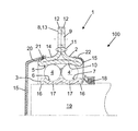
- FIGURE shows a bearing arrangement with an embodiment of a rolling bearing according to the invention in the half axial section. All described and / or illustrated features alone or in any meaningful combination form the subject matter of the present invention, also independent of their summary in the claims or their dependency.
- the single figure shows a schematic representation of a bearing assembly 100 with an embodiment of a rolling bearing 1, which is designed as a radial bearing and is mounted on a shaft 19 to be supported.
- This rolling bearing 1 is particularly suitable for applications in which a misalignment of the shaft to be stored is compensated, and can be used for example in agricultural machinery. Also, the use of the rolling bearing 1 in motor vehicles of any kind is possible.
- the rolling bearing 1 is preferably arranged on the drive side of the shaft to be supported.
- the rolling bearing 1 has two relatively rotatable bearing rings 2, 3, namely an outer ring 2 and an inner ring 3. Between these bearing rings 2, 3, the rolling elements 4, 4 'of the rolling bearing 1 are arranged, which on raceways 5, 6, 7 of Lageringe 2, 3 are unrolled.
- the rolling bearing 1 is designed as a double-row bearing, so that, seen in the axial direction of the rolling bearing 1, two rows of rotating rolling elements 4, 4 'are present.
- the bearing rings 2, 3 are formed by forming, preferably by bending a sheet. To Erzeilung a comparatively high component stiffness and for easy attachment to a non-rotatable component, the bearing rings 2, 3 have a special geometry.
- the inner ring 3 is rotatably connected to the shaft 19, preferably pressed onto this.
- the inner ring 3 has preferably formed by forming raceways 6, 7, in which the rolling elements 4, 4 'are used.
- the rolling bearing 1 can also absorb forces in the axial direction, that is to say in the direction of the longitudinal axis of the shaft 19.
- the inner ring 3 at its axial ends formed by forming sections 16 for radial support and rotationally fixed connection with the shaft 19. These sections 16 point radially inwards and lie firmly on the surface of the shaft.
- the raceway sections 17 likewise formed by forming lie radially inward on the surface of the shaft 19 and thereby increase the frictional force for the rotationally fixed holding of the inner ring 3 on the shaft.
- the outer ring 2 has a tread portion 10, on the radially inner a common raceway 5 for the rolling elements 4, 4 'of the two rows of rolling elements is formed.
- This tread portion 10 is made by a forming process of a flat and then annularly bent sheet metal.
- the outer ring 2 is not only a component of the rolling bearing 1, it also assumes the function of a housing for the rolling bearing 1 with a radially outwardly pointing flange portion 8.
- the flange portion 8 is circular or consists of circumferentially distributed arranged circular sections, and has several arranged through the circumference through holes 9, by means of which the flange portion 8 can be mounted for example on a non-rotatable component of an agricultural machine.
- the outer ring 2 is formed in the half-axial section substantially T-shaped, wherein a leg 13 forms the flange portion and between extending in the axial direction two rows of rolling elements 4, 4 'extends radially outward.
- the outer ring 2 is formed by forming in such a way that at its functional areas, namely the raceway 5 and the flange 8, there is a material doubling, which is preferably generated by a corresponding edge of the originally axially extending sheet metal.
- the material doubling is assigned the reference numeral 11, which by way of example points to a region of the outer ring 2 marked by a circumference.
- the two axial ends 12 of the outer ring 2 underlying sheet metal plate form the radial end of the flange 8, so that in a fastening thereof by means of screws through the circumferentially provided through holes 9 of the flange 8 advantageously a clamping of these ends 12 takes place.
- the raceway 5 having tread portion 10 of the outer ring 2 with its rolling elements 4, 4 'facing side formed radially outwardly curved.
- the outer ring 2 axially opposite each one shoulder portion 14, which serves for conditioning and optionally fixing a cover 15 or seal.
- the connection of the outer ring 2 with the cover 15 is carried out according to the variant shown on the left in the drawing by means of a radially inwardly formed on the cover 15 bead 20 which engages in an annular groove 21 on the shoulder portion 14 of the outer ring 2, or according to the in the
- the drawing figure shows that the cover 15 cooperates with a sealing ring 18 which rotatably mounted on the surface of the shaft 19 and sealingly rests against the cover.
Landscapes
- Engineering & Computer Science (AREA)
- General Engineering & Computer Science (AREA)
- Mechanical Engineering (AREA)
- Manufacturing & Machinery (AREA)
- Rolling Contact Bearings (AREA)
Abstract
Description
- Die Erfindung betrifft ein Wälzlager mit einem Außenring, einem Innenring und dazwischen angeordneten Wälzkörpern, bei dem die Wälzkörper in mehreren axial nebeneinander angeordneten Reihen in mindestens zwei Laufbahnen geführt sind, und bei dem die Lagerringe aus umgeformten Blech hergestellt sind.
- Ein Wälzlager dieser Bauart ist aus der
DD 1 26 199 B2 - Der Erfindung liegt die Aufgabe zugrunde, ein gattungsgemäßes Wälzlager vorzustellen, welches leicht mit einem feststehenden, das Wälzlager tragenden Gegenstand verbindbar ist. Gemäß einer weiteren Aufgabe soll das neue Wälzlager im Vergleich zu dem bekannten Wälzlager steifer ausgebildet sein und daher größere Kräfte übertragen können.
- Die Erfindung geht gemäß den Merkmalen des Hauptanspruchs aus von Wälzlager mit einem Außenring, einem Innenring und dazwischen angeordneten Wälzkörpern, bei dem die Wälzkörper in mehreren axial nebeneinander angeordneten Reihen in mindestens zwei Laufbahnen geführt sind, und bei dem die Lagerringe aus umgeformten Blech hergestellt sind. Zur Lösung der Aufgabe ist vorgesehen, dass der Außenring zumindest einen Flanschabschnitt aufweist, der in Bezug zu einem die zumindest eine Lauffläche des Außenringes aufweisenden Abschnitt des Außenrings abgewinkelt angeordnet ist.
- Dadurch, dass die Lagerringe als Blech-Umformteile ausgebildet sind, kann das Wälzlager in herstellungstechnisch einfacher Weise und damit besonders kostengünstig realisiert werden. Ein Umformteil ist im Sinne der Erfindung ein Bauteil, welches gezielt plastisch in eine andere Form gebracht ist. Dadurch ist eine aufwendige Herstellung der Lagerringe mittels beispielsweise spanender Bearbeitung nicht oder nur teilweise erforderlich. Bevorzugt werden die Lagerringe durch Biegen hergestellt.
- Das erfindungsgemäße Wälzlager bildet eine montagefertige Einheit aus Lager und Gehäuse, da der Lageraußenring mittels des Flanschabschnittes auch Gehäusefunktionen wahrnimmt. Durch die einstückige Anordnung eines Flanschabschnittes an dem Außenring des Wälzlagers ist dieses sehr einfach und schnell beispielsweise mit einer Rahmen- oder Fahrwerksstruktur eines Kraftfahrzeuges verbindbar. Dazu werden einfach Verbindungsmittel durch axiale Öffnungen in dem Flanschabschnitt gesteckt und anschließend beispielsweise in eine Gewindebohrung des feststehenden Bauteils eingeschraubt. Das Lösen dieser Lagerbefestigung erfolgt in umgekehrter Reihenfolge und ebenso einfacher Weise.
- Vorzugsweise ist vorgesehen, dass der Außenring eine durch den genannten Umformvorgang gebildete Materialdoppelung des Blechmaterials aufweist, wobei zwei Lagen des gleichen Materials zumindest teilweise übereinander in Berührkontakt liegen. Bevorzugt ist die Materialdopplung im Bereich der Lauffläche für die Wälzkörper und/oder im Bereich des Flanschabschnittes ausgebildet ist. Hierdurch ist der Außenring des Wälzlagers in besonderer Weise versteift, so dass dieser zur Befestigung an einem drehfesten Bauteil sehr gut geeignet ist.
- In Weiterbildung dieser Variante ist mit Vorteil vorgesehen, dass bei dem Außenring mit Materialdoppelung die axialen Seiten des ursprünglich kreisringförmigen Blechs nach dem Umformvorgang das radiale Ende des Flansches bilden.
- Der Innenring des Wälzlagers gemäß der Erfindung weist zwei vorzugsweise durch Umformen gebildete Laufbahnen bzw. Laufrillen auf. Der Außenring hingegen kann eine für beide Wälzkörperreihen gemeinsame, durch Umformen gebildete Lauffläche aufweisen, oder zwei gesonderte, durch Umformen gebildete Laufbahnen.
- Gemäß einer Ausgestaltung ist vorgesehen, dass die den Wälzkörpern zugewandte einzige Lauffläche des Laufflächenabschnitts des Außenrings nach radial außen gewölbt ausgebildet ist. Dadurch ist das Wälzlager selbstausrichtend, da der Außenring gegenüber dem Innenring zumindest in geringem Maße verkippbar ist. Eine etwaige Schiefstellung einer zu lagernden Welle ist hierdurch besonders gut auszugleichen.
- Bei dem Außenring ist bevorzugt vorgesehen, dass dieser im hälftigen Axialschnitt eine weitgehend T-förmige Geometrie aufweist, wobei ein Schenkel des Außenringes zwischen den in axialer Richtung angeordneten zumindest beiden Wälzkörperreihen radial nach außen gerichtet angeordnet ist. Die T-Form bietet bekanntermaßen eine hohe Steifigkeit im Hinblick auf die Gehäusefunktion des umgeformten Teils sowie im Hinblick auf seine Funktion als Außenring für das Wälzlager.
- Außerdem wird es als vorteilhaft beurteilt, wenn der Außenring wenigstens einen Schulterabschnitt zur Anlage und gegebenenfalls Fixierung einer Abdeckung und/oder Dichtung aufweist. Die Verbindung der Abdeckung oder des Dichtungsbauteils kann durch eine Nut-Wulst-Verbindung oder durch ein Verprägen oder Verstemmen dieser Bauteile erfolgen.
- Schließlich kann vorgesehen sein, dass der Innenring an seinen axialen Enden jeweils einen durch Umformen gebildeten und nach radial innen abgewinkelten Endabschnitt aufweist. Durch dieses Konstruktionsdetail kann der Innenring ohne eine Materialdopplung vergleichsweise steif ausgebildet werden, da sich die radial nach innen abgewinkelten axialen Enden des Innenringes beispielsweise auf einer Welle radial abstützen können. Durch diese Klemmwirkung ist auch eine drehfeste Verbindung des Lagerinnenringes mit der Welle realisierbar.
- Bevorzugt werden der Innenring und/oder der Außenring des Wälzlagers aus einer Blechtafel hergestellt, wobei jeweils ein Blechstreifen abgeschnitten, dessen längsseitigen Enden miteinander zu einem ringförmigen Streifen verbunden und dieser Blechring anschließend zu einem Lagerring umgeformt wird.
- Das Wälzlager kann mit oder ohne Käfig für die Wälzkörper ausgebildet sein. Das Wälzlager kann ferner ein Axiallager sein. Auch kann das Wälzlager als ein Kugellager, Zylinderrollenlager oder Nadellager ausgebildet sein.
- Die Erfindung wird im Folgenden anhand der beiliegenden Zeichnung an einem Ausführungsbeispiel näher erläutert. Die einzige Figur zeigt eine Lageranordnung mit einer Ausführungsform eines erfindungsgemäßen Wälzlagers im hälftigen Axialschnitt. Dabei bilden alle beschriebenen und/oder bildlich dargestellten Merkmale für sich oder in beliebiger sinnvoller Kombination den Gegenstand der vorliegenden Erfindung, auch unabhängig von ihrer Zusammenfassung in den Ansprüchen oder deren Rückbeziehung.
- Die einzige Figur zeigt in schematischer Darstellung eine Lageranordnung 100 mit einer Ausführungsform eines Wälzlagers 1, welches als Radiallager ausgebildet ist und auf einer zu lagernden Welle 19 befestigt ist. Dieses Wälzlager 1 ist besonders für Anwendungsfälle geeignet, bei denen eine Schiefstellung der zu lagernden Welle auszugleichen ist, und kann beispielsweise in Landmaschinen eingesetzt werden. Auch ist der Einsatz des Wälzlagers 1 in Kraftfahrzeugen jeglicher Art möglich. Das Wälzlager 1 ist vorzugsweise an der Antriebsseite der zu lagernden Welle angeordnet.
- Das Wälzlager 1 weist zwei relativ zueinander drehbare Lagerringe 2, 3 auf, nämlich einen Außenring 2 und einen Innenring 3. Zwischen diesen Lagerringen 2, 3 sind die Wälzkörper 4, 4' des Wälzlagers 1 angeordnet, welche auf Laufbahnen 5, 6, 7 der Lageringe 2, 3 abrollbar sind. Das Wälzlager 1 ist als zweireihiges Lager ausgebildet, so dass, in axialer Richtung des Wälzlagers 1 gesehen, zwei Reihen mit umlaufenden Wälzkörpern 4, 4' vorhanden sind.
- Um das Wälzlager 1 besonders kostengünstig realisieren zu können, sind die Lagerringe 2, 3 durch Umformen, vorzugsweise durch Biegen eines Blechs gebildet. Zur Erzeilung einer vergleichsweise hohen Bauteilsteifigkeit sowie zu leichten Befestigung an einem drehfesten Bauteil weisen die Lagerringe 2, 3 eine besondere Geometrie auf.
- Der Innenring 3 ist mit der Welle 19 drehfest verbunden, vorzugsweise auf diese aufgepresst. Der Innenring 3 weist bevorzugt durch Umformen gebildete Laufbahnen 6, 7 auf, in welchen die Wälzkörper 4, 4' eingesetzt sind. Dadurch kann das Wälzlager 1 Kräfte auch in axialer Richtung, das heißt in Richtung der Längsachse der Welle 19, aufnehmen.
- In dem gewählten Ausführungsbeispiel weist der Innenring 3 an seinen axialen Enden durch Umformen gebildete Abschnitte 16 zum radialen Abstützen und drehfesten Verbinden mit der Welle 19 auf. Diese Abschnitte 16 weisen radial nach innen und liegen auf der Oberfläche der Welle fest auf. Die ebenfalls durch Umformen gebildeten Laufbahnabschnitte 17 liegen radial innen auf der Oberfläche der Welle 19 auf und erhöhen dadurch die Reibkraft zum verdrehfesten Halten des Innenringes 3 auf der Welle.
- Der Außenring 2 weist einen Laufflächenabschnitt 10 auf, an dem radial innen eine gemeinsame Laufbahn 5 für die Wälzkörper 4, 4' der beiden Wälzkörperreihen ausgebildet ist. Dieser Laufflächenabschnitt 10 ist durch einen Umformprozess aus einem ebenen und anschließend ringförmig gebogenen Blech hergestellt. Der Außenring 2 ist nicht nur ein Bestandteil des Wälzlagers 1, er übernimmt mit einem radial nach außen weisenden Flanschabschnitt 8 zugleich auch die Funktion eines Gehäuses für das Wälzlager 1. Der Flanschabschnitt 8 ist kreisförmig ausgebildet oder besteht aus umfangsverteilt angeordneten Kreisabschnitten, und verfügt über mehrere über dem Umfang angeordnete Durchgangsbohrungen 9, mittels welchen der Flanschabschnitt 8 beispielsweise an einem drehfesten Bauteil einer Landmaschine montiert werden kann.
- Der Außenring 2 ist im hälftigen Axialschnitt im Wesentlichen T-förmig ausgebildet, wobei ein Schenkel 13 den Flanschabschnitt bildet und sich zwischen den in axialer Richtung angeordneten zwei Reihen von Wälzkörpern 4, 4' radial nach außen erstreckt.
- Der Außenring 2 ist in der Weise durch Umformen gebildet, dass an seinen Funktionsbereichen, nämlich der Laufbahn 5 und dem Flanschabschnitt 8, eine Materialdopplung vorliegt, welche bevorzugt durch eine entsprechende Umkantung des sich ursprünglich axial erstreckenden Bleches erzeugt ist. Der Materialdopplung ist das Bezugszeichen 11 zugeordnet, welches beispielhaft auf einen durch Umkreisung markierten Bereich des Außenringes 2 weist. Die beiden axialen Enden 12 der dem Außenring 2 zugrunde liegenden Blechplatte bilden das radiale Ende des Flanschabschnittes 8, so dass bei einem Befestigen desselben mittels Schrauben durch die umlaufend vorgesehenen Durchgangsbohrungen 9 des Flanschabschnittes 8 vorteilhaft ein Zusammenklemmen dieser Enden 12 erfolgt.
- Bevorzugt ist der die Laufbahn 5 aufweisende Laufflächenabschnitt 10 des Außenrings 2 mit seiner den Wälzkörpern 4, 4' zugewandten Seite nach radial außen gewölbt ausgebildet.
- Schließlich weist der Außenring 2 axial gegenüberliegend jeweils einen Schulterabschnitt 14 auf, welcher zur Anlage und gegebenenfalls Fixierung einer Abdeckung 15 oder Dichtung dient. Die Verbindung des Außenringes 2 mit der Abdeckung 15 erfolgt gemäß der in der Zeichnungsfigur links dargestellte Variante mittels eines radial innen an der Abdeckung 15 ausgebildeten Wulstes 20, der in eine Ringnut 21 an dem Schulterabschnitt 14 des Außenringes 2 eingreift, oder gemäß der auf in der rechten Bildhälfte abgebildeten Variante über eine Verstemmung von Material der Abdeckung 15 in die Ringnut 21. Außerdem zeigt die Zeichnungsfigur, dass die Abdeckung 15 mit einem Dichtring 18 zusammenwirkt, der drehfest auf der Oberfläche der Welle 19 befestigt und abdichtend an der Abdeckung anliegt.
-
- 1
- Wälzlager
- 2
- Außenring
- 3
- Innenring
- 4
- Wälzkörper, Wälzkörperreihe
- 4'
- Wälzkörper, Wälzkörperreihe
- 5
- Laufbahn am Außenring
- 6
- Laufbahn am Innenring
- 7
- Laufbahn am Innenring
- 8
- Flanschabschnitt
- 9
- Durchgangsbohrung
- 10
- Laufflächenabschnitt
- 11
- Materialdopplung
- 12
- Freie Ende des Außenringblechs 2
- 13
- Schenkel
- 14
- Schulterabschnitt des Außenrings 2
- 15
- Abdeckung
- 16
- Endabschnitt des Innenrings 2
- 17
- Laufbahnabschnitt des Innenrings 2
- 18
- Dichtring
- 19
- Welle
- 20
- Wulst am Schulterabschnitt der Abdeckung 15
- 21
- Ringnut am Außenring 3
- 22
- Verprägung
- 100
- Lageranordnung
Claims (8)
- Wälzlager (1) mit einem Außenring (2), einem Innenring (3) und dazwischen angeordneten Wälzkörpern (4, 4'), bei dem die Wälzkörper (4, 4') in mehreren axial nebeneinander angeordneten Reihen in mindestens zwei Laufbahnen (5, 6, 7) geführt sind, und bei dem die Lagerringe (2, 3) aus umgeformten Blech hergestellt sind, dadurch gekennzeichnet, dass der Außenring (2) zumindest einen Flanschabschnitt (8) aufweist, der in Bezug zu einem die zumindest eine Lauffläche (5) des Außenringes (2) aufweisenden Abschnitt (10) des Außenrings (2) abgewinkelt angeordnet ist.
- Wälzlager nach Anspruch 1, dadurch gekennzeichnet, dass der Außenring (2) eine durch das Umformen gebildete Materialdoppelung (11) aufweist, die im Bereich der Laufbahn (5) für die Wälzkörper (4, 4') und/oder im Bereich eines Flansches (8) ausgebildet ist.
- Wälzlager nach Anspruch 2, dadurch gekennzeichnet, dass bei dem Außenring (2) mit Materialdoppelung (11) die freien axialen Seiten (12) des zugrunde liegenden Blechringes das radiale Ende des Flansches (8) bilden.
- Wälzlager nach einem der vorherigen Ansprüche, dadurch gekennzeichnet, dass der Innenring (3) zwei durch Umformen gebildete Laufbahnen (6, 7) und der Außenring (2) eine gemeinsame durch Umformen gebildete Laufbahn (5) oder zwei gesonderte durch Umformen gebildete Laufbahnen für die Wälzkörper (4, 4') der beide Wälzkörperreihen aufweist.
- Wälzlager nach einem der vorherigen Ansprüche, dadurch gekennzeichnet, dass der Außenring (2) im hälftigen Axialschnitt eine weitgehend T-förmiges Geometrie aufweist, wobei zwischen den in axialer Richtung angeordneten beiden Wälzkörperreihen (4, 4') ein Schenkel (13) Außenringes (2) radial nach außen gerichtet ist.
- Wälzlager nach einem der vorherigen Ansprüche, dadurch gekennzeichnet, dass der Außenring (2) wenigstens einen Schulterabschnitt (14) zur Anlage und gegebenenfalls Fixierung einer Abdeckung (15) und/oder Dichtung aufweist.
- Wälzlager nach einem der vorherigen Ansprüche, dadurch gekennzeichnet, dass die den Wälzkörpern (4, 4') zugewandte einzige Laufbahn (5) des Laufflächenabschnitts (10) des Außenrings (2) nach radial außen gewölbt ausgebildet ist.
- Wälzlager nach einem der vorherigen Ansprüche, dadurch gekennzeichnet, dass der Innenring (3) an seinen axialen Enden jeweils einen durch Umformen gebildeten und nach radial innen abgewinkelten Endabschnitt (16) aufweist.
Applications Claiming Priority (1)
| Application Number | Priority Date | Filing Date | Title |
|---|---|---|---|
| DE102009053799A DE102009053799A1 (de) | 2009-11-18 | 2009-11-18 | Wälzlager mit aus Blech hergestellten Lagerringen |
Publications (3)
| Publication Number | Publication Date |
|---|---|
| EP2325509A2 true EP2325509A2 (de) | 2011-05-25 |
| EP2325509A3 EP2325509A3 (de) | 2014-12-31 |
| EP2325509B1 EP2325509B1 (de) | 2017-01-04 |
Family
ID=43333014
Family Applications (1)
| Application Number | Title | Priority Date | Filing Date |
|---|---|---|---|
| EP10188804.8A Not-in-force EP2325509B1 (de) | 2009-11-18 | 2010-10-26 | Wälzlager mit aus blech hergestellten lagerringen |
Country Status (2)
| Country | Link |
|---|---|
| EP (1) | EP2325509B1 (de) |
| DE (1) | DE102009053799A1 (de) |
Cited By (4)
| Publication number | Priority date | Publication date | Assignee | Title |
|---|---|---|---|---|
| WO2016022023A1 (en) * | 2014-08-08 | 2016-02-11 | Jla Loading Technology B.V. | Swivel device |
| CN108730333A (zh) * | 2018-08-09 | 2018-11-02 | 常熟得美零部件有限公司 | 免维护农机滚轮轴承组件 |
| CN111322318A (zh) * | 2018-12-17 | 2020-06-23 | 斯凯孚公司 | 具有滚动轴承的系统 |
| CN113790157A (zh) * | 2021-10-22 | 2021-12-14 | 珠海格力电器股份有限公司 | 轴承气缸、压缩机和空调器 |
Families Citing this family (1)
| Publication number | Priority date | Publication date | Assignee | Title |
|---|---|---|---|---|
| DE102024127617A1 (de) * | 2024-09-24 | 2026-03-26 | Technische Universität Darmstadt, Körperschaft des öffentlichen Rechts | Wälzlager und Verfahren zu dessen Herstellung und Montage |
Citations (1)
| Publication number | Priority date | Publication date | Assignee | Title |
|---|---|---|---|---|
| DD126199A1 (de) | 1975-04-24 | 1977-06-29 |
Family Cites Families (4)
| Publication number | Priority date | Publication date | Assignee | Title |
|---|---|---|---|---|
| FR1566650A (de) * | 1968-03-26 | 1969-05-09 | ||
| SE461606B (sv) * | 1988-02-11 | 1990-03-05 | Skf Nova Ab | Foerfarande foer framstaellning av tvaaradiga vinkelkontaktkullager |
| DE19802454A1 (de) * | 1998-01-23 | 1999-08-05 | Erwin Kunz Ag Axial Kugellager | Kugellager |
| DE19908158A1 (de) * | 1999-02-25 | 2000-08-31 | Schaeffler Waelzlager Ohg | Lagerungsbaugruppe |
-
2009
- 2009-11-18 DE DE102009053799A patent/DE102009053799A1/de not_active Withdrawn
-
2010
- 2010-10-26 EP EP10188804.8A patent/EP2325509B1/de not_active Not-in-force
Patent Citations (1)
| Publication number | Priority date | Publication date | Assignee | Title |
|---|---|---|---|---|
| DD126199A1 (de) | 1975-04-24 | 1977-06-29 |
Cited By (4)
| Publication number | Priority date | Publication date | Assignee | Title |
|---|---|---|---|---|
| WO2016022023A1 (en) * | 2014-08-08 | 2016-02-11 | Jla Loading Technology B.V. | Swivel device |
| CN108730333A (zh) * | 2018-08-09 | 2018-11-02 | 常熟得美零部件有限公司 | 免维护农机滚轮轴承组件 |
| CN111322318A (zh) * | 2018-12-17 | 2020-06-23 | 斯凯孚公司 | 具有滚动轴承的系统 |
| CN113790157A (zh) * | 2021-10-22 | 2021-12-14 | 珠海格力电器股份有限公司 | 轴承气缸、压缩机和空调器 |
Also Published As
| Publication number | Publication date |
|---|---|
| EP2325509B1 (de) | 2017-01-04 |
| EP2325509A3 (de) | 2014-12-31 |
| DE102009053799A1 (de) | 2011-05-19 |
Similar Documents
| Publication | Publication Date | Title |
|---|---|---|
| EP1361373B1 (de) | Achsgetriebe für ein Kraftfahrzeug, mit zweireihigen Schrägkugellagern | |
| EP1994292B1 (de) | Verfahren zum herstellen eines einbaufertigen nadellager mit innen- und aussenring | |
| DE102009004920B4 (de) | Kombiniertes Radial-Axialwälzlager | |
| DE102013008977A1 (de) | Wälzlagermontagevorrichtung für Lenksäule | |
| EP1090233A1 (de) | Mehrreihiges radiallager | |
| DE102011053323A1 (de) | Wellgetriebe | |
| DE10306926B4 (de) | Axiallager | |
| EP2325509B1 (de) | Wälzlager mit aus blech hergestellten lagerringen | |
| DE102011079750A1 (de) | Kombiniertes Radial-Axial-Rollenlager | |
| DE102016211196A1 (de) | Wälzlagereinheit | |
| DE10220688B4 (de) | Wälzlager zur Lagerung einer Lenkwelle | |
| DE10152484A1 (de) | Abdichtung für ein Ausrücklager | |
| WO2002044578A1 (de) | Abdichtung für ein ausrücklager | |
| DE4438957C1 (de) | Axiallager mit einer benachbarten Abdichtung | |
| DE69703347T2 (de) | Übertragungsgelenkkreuz und entsprechendes übertragungsgelenk | |
| DE102015220151B4 (de) | Lageranordnung und Dichtung | |
| DE102006021446A1 (de) | Welle einer Wasserpumpe eines Verbrennungsmotors | |
| DE102013009113A1 (de) | Wälzlagermontagevorrichtung für Lenkrad | |
| DE10141113A1 (de) | Sicherung von axial aufeinander schiebbaren Bauteilen | |
| DE102017119986A1 (de) | Wälzlageranordnung für eine Lenksäule | |
| DE102006031029A1 (de) | Radlagereinheit | |
| WO2011047920A1 (de) | Radial-rollenwälzlager mit separaten borden aus blech | |
| DE102008031578A1 (de) | Lageranordnung und Verfahren in ihrer Montage | |
| DE102015215192A1 (de) | Radlagereinheit | |
| WO2003033925A1 (de) | Linearwälzlager |
Legal Events
| Date | Code | Title | Description |
|---|---|---|---|
| PUAI | Public reference made under article 153(3) epc to a published international application that has entered the european phase |
Free format text: ORIGINAL CODE: 0009012 |
|
| 17P | Request for examination filed |
Effective date: 20101026 |
|
| AK | Designated contracting states |
Kind code of ref document: A2 Designated state(s): AL AT BE BG CH CY CZ DE DK EE ES FI FR GB GR HR HU IE IS IT LI LT LU LV MC MK MT NL NO PL PT RO RS SE SI SK SM TR |
|
| AX | Request for extension of the european patent |
Extension state: BA ME |
|
| RAP1 | Party data changed (applicant data changed or rights of an application transferred) |
Owner name: SCHAEFFLER TECHNOLOGIES AG & CO. KG |
|
| RAP1 | Party data changed (applicant data changed or rights of an application transferred) |
Owner name: SCHAEFFLER TECHNOLOGIES GMBH & CO. KG |
|
| PUAL | Search report despatched |
Free format text: ORIGINAL CODE: 0009013 |
|
| RIC1 | Information provided on ipc code assigned before grant |
Ipc: F16C 33/64 20060101ALI20141119BHEP Ipc: F16C 33/58 20060101AFI20141119BHEP Ipc: F16C 19/18 20060101ALI20141119BHEP Ipc: F16C 23/08 20060101ALI20141119BHEP |
|
| AK | Designated contracting states |
Kind code of ref document: A3 Designated state(s): AL AT BE BG CH CY CZ DE DK EE ES FI FR GB GR HR HU IE IS IT LI LT LU LV MC MK MT NL NO PL PT RO RS SE SI SK SM TR |
|
| AX | Request for extension of the european patent |
Extension state: BA ME |
|
| RAP1 | Party data changed (applicant data changed or rights of an application transferred) |
Owner name: SCHAEFFLER TECHNOLOGIES AG & CO. KG |
|
| GRAP | Despatch of communication of intention to grant a patent |
Free format text: ORIGINAL CODE: EPIDOSNIGR1 |
|
| INTG | Intention to grant announced |
Effective date: 20160810 |
|
| GRAS | Grant fee paid |
Free format text: ORIGINAL CODE: EPIDOSNIGR3 |
|
| GRAA | (expected) grant |
Free format text: ORIGINAL CODE: 0009210 |
|
| AK | Designated contracting states |
Kind code of ref document: B1 Designated state(s): AL AT BE BG CH CY CZ DE DK EE ES FI FR GB GR HR HU IE IS IT LI LT LU LV MC MK MT NL NO PL PT RO RS SE SI SK SM TR |
|
| REG | Reference to a national code |
Ref country code: GB Ref legal event code: FG4D Free format text: NOT ENGLISH |
|
| REG | Reference to a national code |
Ref country code: CH Ref legal event code: EP |
|
| REG | Reference to a national code |
Ref country code: AT Ref legal event code: REF Ref document number: 859546 Country of ref document: AT Kind code of ref document: T Effective date: 20170115 |
|
| REG | Reference to a national code |
Ref country code: IE Ref legal event code: FG4D Free format text: LANGUAGE OF EP DOCUMENT: GERMAN |
|
| REG | Reference to a national code |
Ref country code: DE Ref legal event code: R096 Ref document number: 502010012983 Country of ref document: DE |
|
| REG | Reference to a national code |
Ref country code: LT Ref legal event code: MG4D Ref country code: NL Ref legal event code: MP Effective date: 20170104 |
|
| PG25 | Lapsed in a contracting state [announced via postgrant information from national office to epo] |
Ref country code: NL Free format text: LAPSE BECAUSE OF FAILURE TO SUBMIT A TRANSLATION OF THE DESCRIPTION OR TO PAY THE FEE WITHIN THE PRESCRIBED TIME-LIMIT Effective date: 20170104 |
|
| PG25 | Lapsed in a contracting state [announced via postgrant information from national office to epo] |
Ref country code: HR Free format text: LAPSE BECAUSE OF FAILURE TO SUBMIT A TRANSLATION OF THE DESCRIPTION OR TO PAY THE FEE WITHIN THE PRESCRIBED TIME-LIMIT Effective date: 20170104 Ref country code: NO Free format text: LAPSE BECAUSE OF FAILURE TO SUBMIT A TRANSLATION OF THE DESCRIPTION OR TO PAY THE FEE WITHIN THE PRESCRIBED TIME-LIMIT Effective date: 20170404 Ref country code: IS Free format text: LAPSE BECAUSE OF FAILURE TO SUBMIT A TRANSLATION OF THE DESCRIPTION OR TO PAY THE FEE WITHIN THE PRESCRIBED TIME-LIMIT Effective date: 20170504 Ref country code: GR Free format text: LAPSE BECAUSE OF FAILURE TO SUBMIT A TRANSLATION OF THE DESCRIPTION OR TO PAY THE FEE WITHIN THE PRESCRIBED TIME-LIMIT Effective date: 20170405 Ref country code: LT Free format text: LAPSE BECAUSE OF FAILURE TO SUBMIT A TRANSLATION OF THE DESCRIPTION OR TO PAY THE FEE WITHIN THE PRESCRIBED TIME-LIMIT Effective date: 20170104 Ref country code: FI Free format text: LAPSE BECAUSE OF FAILURE TO SUBMIT A TRANSLATION OF THE DESCRIPTION OR TO PAY THE FEE WITHIN THE PRESCRIBED TIME-LIMIT Effective date: 20170104 |
|
| PG25 | Lapsed in a contracting state [announced via postgrant information from national office to epo] |
Ref country code: BG Free format text: LAPSE BECAUSE OF FAILURE TO SUBMIT A TRANSLATION OF THE DESCRIPTION OR TO PAY THE FEE WITHIN THE PRESCRIBED TIME-LIMIT Effective date: 20170404 Ref country code: ES Free format text: LAPSE BECAUSE OF FAILURE TO SUBMIT A TRANSLATION OF THE DESCRIPTION OR TO PAY THE FEE WITHIN THE PRESCRIBED TIME-LIMIT Effective date: 20170104 Ref country code: RS Free format text: LAPSE BECAUSE OF FAILURE TO SUBMIT A TRANSLATION OF THE DESCRIPTION OR TO PAY THE FEE WITHIN THE PRESCRIBED TIME-LIMIT Effective date: 20170104 Ref country code: SE Free format text: LAPSE BECAUSE OF FAILURE TO SUBMIT A TRANSLATION OF THE DESCRIPTION OR TO PAY THE FEE WITHIN THE PRESCRIBED TIME-LIMIT Effective date: 20170104 Ref country code: LV Free format text: LAPSE BECAUSE OF FAILURE TO SUBMIT A TRANSLATION OF THE DESCRIPTION OR TO PAY THE FEE WITHIN THE PRESCRIBED TIME-LIMIT Effective date: 20170104 Ref country code: PL Free format text: LAPSE BECAUSE OF FAILURE TO SUBMIT A TRANSLATION OF THE DESCRIPTION OR TO PAY THE FEE WITHIN THE PRESCRIBED TIME-LIMIT Effective date: 20170104 Ref country code: PT Free format text: LAPSE BECAUSE OF FAILURE TO SUBMIT A TRANSLATION OF THE DESCRIPTION OR TO PAY THE FEE WITHIN THE PRESCRIBED TIME-LIMIT Effective date: 20170504 |
|
| REG | Reference to a national code |
Ref country code: DE Ref legal event code: R097 Ref document number: 502010012983 Country of ref document: DE |
|
| PG25 | Lapsed in a contracting state [announced via postgrant information from national office to epo] |
Ref country code: RO Free format text: LAPSE BECAUSE OF FAILURE TO SUBMIT A TRANSLATION OF THE DESCRIPTION OR TO PAY THE FEE WITHIN THE PRESCRIBED TIME-LIMIT Effective date: 20170104 Ref country code: SK Free format text: LAPSE BECAUSE OF FAILURE TO SUBMIT A TRANSLATION OF THE DESCRIPTION OR TO PAY THE FEE WITHIN THE PRESCRIBED TIME-LIMIT Effective date: 20170104 Ref country code: CZ Free format text: LAPSE BECAUSE OF FAILURE TO SUBMIT A TRANSLATION OF THE DESCRIPTION OR TO PAY THE FEE WITHIN THE PRESCRIBED TIME-LIMIT Effective date: 20170104 Ref country code: EE Free format text: LAPSE BECAUSE OF FAILURE TO SUBMIT A TRANSLATION OF THE DESCRIPTION OR TO PAY THE FEE WITHIN THE PRESCRIBED TIME-LIMIT Effective date: 20170104 |
|
| REG | Reference to a national code |
Ref country code: FR Ref legal event code: PLFP Year of fee payment: 8 |
|
| PLBE | No opposition filed within time limit |
Free format text: ORIGINAL CODE: 0009261 |
|
| STAA | Information on the status of an ep patent application or granted ep patent |
Free format text: STATUS: NO OPPOSITION FILED WITHIN TIME LIMIT |
|
| PG25 | Lapsed in a contracting state [announced via postgrant information from national office to epo] |
Ref country code: DK Free format text: LAPSE BECAUSE OF FAILURE TO SUBMIT A TRANSLATION OF THE DESCRIPTION OR TO PAY THE FEE WITHIN THE PRESCRIBED TIME-LIMIT Effective date: 20170104 Ref country code: SM Free format text: LAPSE BECAUSE OF FAILURE TO SUBMIT A TRANSLATION OF THE DESCRIPTION OR TO PAY THE FEE WITHIN THE PRESCRIBED TIME-LIMIT Effective date: 20170104 |
|
| 26N | No opposition filed |
Effective date: 20171005 |
|
| PGFP | Annual fee paid to national office [announced via postgrant information from national office to epo] |
Ref country code: FR Payment date: 20171031 Year of fee payment: 8 |
|
| PG25 | Lapsed in a contracting state [announced via postgrant information from national office to epo] |
Ref country code: SI Free format text: LAPSE BECAUSE OF FAILURE TO SUBMIT A TRANSLATION OF THE DESCRIPTION OR TO PAY THE FEE WITHIN THE PRESCRIBED TIME-LIMIT Effective date: 20170104 |
|
| PGFP | Annual fee paid to national office [announced via postgrant information from national office to epo] |
Ref country code: IT Payment date: 20171020 Year of fee payment: 8 Ref country code: GB Payment date: 20171101 Year of fee payment: 8 |
|
| REG | Reference to a national code |
Ref country code: DE Ref legal event code: R119 Ref document number: 502010012983 Country of ref document: DE |
|
| PG25 | Lapsed in a contracting state [announced via postgrant information from national office to epo] |
Ref country code: MC Free format text: LAPSE BECAUSE OF FAILURE TO SUBMIT A TRANSLATION OF THE DESCRIPTION OR TO PAY THE FEE WITHIN THE PRESCRIBED TIME-LIMIT Effective date: 20170104 |
|
| REG | Reference to a national code |
Ref country code: CH Ref legal event code: PL |
|
| REG | Reference to a national code |
Ref country code: IE Ref legal event code: MM4A |
|
| PG25 | Lapsed in a contracting state [announced via postgrant information from national office to epo] |
Ref country code: DE Free format text: LAPSE BECAUSE OF NON-PAYMENT OF DUE FEES Effective date: 20180501 Ref country code: LU Free format text: LAPSE BECAUSE OF NON-PAYMENT OF DUE FEES Effective date: 20171026 Ref country code: CH Free format text: LAPSE BECAUSE OF NON-PAYMENT OF DUE FEES Effective date: 20171031 Ref country code: LI Free format text: LAPSE BECAUSE OF NON-PAYMENT OF DUE FEES Effective date: 20171031 |
|
| REG | Reference to a national code |
Ref country code: BE Ref legal event code: MM Effective date: 20171031 |
|
| PG25 | Lapsed in a contracting state [announced via postgrant information from national office to epo] |
Ref country code: BE Free format text: LAPSE BECAUSE OF NON-PAYMENT OF DUE FEES Effective date: 20171031 |
|
| PG25 | Lapsed in a contracting state [announced via postgrant information from national office to epo] |
Ref country code: MT Free format text: LAPSE BECAUSE OF FAILURE TO SUBMIT A TRANSLATION OF THE DESCRIPTION OR TO PAY THE FEE WITHIN THE PRESCRIBED TIME-LIMIT Effective date: 20170104 |
|
| PG25 | Lapsed in a contracting state [announced via postgrant information from national office to epo] |
Ref country code: IE Free format text: LAPSE BECAUSE OF NON-PAYMENT OF DUE FEES Effective date: 20171026 |
|
| REG | Reference to a national code |
Ref country code: AT Ref legal event code: MM01 Ref document number: 859546 Country of ref document: AT Kind code of ref document: T Effective date: 20171026 |
|
| PG25 | Lapsed in a contracting state [announced via postgrant information from national office to epo] |
Ref country code: AT Free format text: LAPSE BECAUSE OF NON-PAYMENT OF DUE FEES Effective date: 20171026 |
|
| GBPC | Gb: european patent ceased through non-payment of renewal fee |
Effective date: 20181026 |
|
| PG25 | Lapsed in a contracting state [announced via postgrant information from national office to epo] |
Ref country code: HU Free format text: LAPSE BECAUSE OF FAILURE TO SUBMIT A TRANSLATION OF THE DESCRIPTION OR TO PAY THE FEE WITHIN THE PRESCRIBED TIME-LIMIT; INVALID AB INITIO Effective date: 20101026 |
|
| PG25 | Lapsed in a contracting state [announced via postgrant information from national office to epo] |
Ref country code: FR Free format text: LAPSE BECAUSE OF NON-PAYMENT OF DUE FEES Effective date: 20181031 |
|
| PG25 | Lapsed in a contracting state [announced via postgrant information from national office to epo] |
Ref country code: IT Free format text: LAPSE BECAUSE OF NON-PAYMENT OF DUE FEES Effective date: 20181026 Ref country code: GB Free format text: LAPSE BECAUSE OF NON-PAYMENT OF DUE FEES Effective date: 20181026 Ref country code: CY Free format text: LAPSE BECAUSE OF NON-PAYMENT OF DUE FEES Effective date: 20170104 |
|
| PG25 | Lapsed in a contracting state [announced via postgrant information from national office to epo] |
Ref country code: MK Free format text: LAPSE BECAUSE OF FAILURE TO SUBMIT A TRANSLATION OF THE DESCRIPTION OR TO PAY THE FEE WITHIN THE PRESCRIBED TIME-LIMIT Effective date: 20170104 |
|
| PG25 | Lapsed in a contracting state [announced via postgrant information from national office to epo] |
Ref country code: TR Free format text: LAPSE BECAUSE OF FAILURE TO SUBMIT A TRANSLATION OF THE DESCRIPTION OR TO PAY THE FEE WITHIN THE PRESCRIBED TIME-LIMIT Effective date: 20170104 |
|
| PG25 | Lapsed in a contracting state [announced via postgrant information from national office to epo] |
Ref country code: AL Free format text: LAPSE BECAUSE OF FAILURE TO SUBMIT A TRANSLATION OF THE DESCRIPTION OR TO PAY THE FEE WITHIN THE PRESCRIBED TIME-LIMIT Effective date: 20170104 |
|
| P01 | Opt-out of the competence of the unified patent court (upc) registered |
Effective date: 20230524 |