EP2325344A2 - Verbesserte thermoelektrische Materiale des P-Typs, Verfahren zur Herstellung und Verwendung derselben - Google Patents
Verbesserte thermoelektrische Materiale des P-Typs, Verfahren zur Herstellung und Verwendung derselben Download PDFInfo
- Publication number
- EP2325344A2 EP2325344A2 EP10186169A EP10186169A EP2325344A2 EP 2325344 A2 EP2325344 A2 EP 2325344A2 EP 10186169 A EP10186169 A EP 10186169A EP 10186169 A EP10186169 A EP 10186169A EP 2325344 A2 EP2325344 A2 EP 2325344A2
- Authority
- EP
- European Patent Office
- Prior art keywords
- thermoelectric
- stoichiometric
- rod
- composition
- zone
- Prior art date
- Legal status (The legal status is an assumption and is not a legal conclusion. Google has not performed a legal analysis and makes no representation as to the accuracy of the status listed.)
- Granted
Links
Images






Classifications
-
- C—CHEMISTRY; METALLURGY
- C22—METALLURGY; FERROUS OR NON-FERROUS ALLOYS; TREATMENT OF ALLOYS OR NON-FERROUS METALS
- C22C—ALLOYS
- C22C12/00—Alloys based on antimony or bismuth
-
- C—CHEMISTRY; METALLURGY
- C22—METALLURGY; FERROUS OR NON-FERROUS ALLOYS; TREATMENT OF ALLOYS OR NON-FERROUS METALS
- C22C—ALLOYS
- C22C1/00—Making non-ferrous alloys
- C22C1/04—Making non-ferrous alloys by powder metallurgy
- C22C1/047—Making non-ferrous alloys by powder metallurgy comprising intermetallic compounds
-
- C—CHEMISTRY; METALLURGY
- C22—METALLURGY; FERROUS OR NON-FERROUS ALLOYS; TREATMENT OF ALLOYS OR NON-FERROUS METALS
- C22C—ALLOYS
- C22C1/00—Making non-ferrous alloys
- C22C1/04—Making non-ferrous alloys by powder metallurgy
- C22C1/05—Mixtures of metal powder with non-metallic powder
- C22C1/051—Making hard metals based on borides, carbides, nitrides, oxides or silicides; Preparation of the powder mixture used as the starting material therefor
- C22C1/053—Making hard metals based on borides, carbides, nitrides, oxides or silicides; Preparation of the powder mixture used as the starting material therefor with in situ formation of hard compounds
-
- C—CHEMISTRY; METALLURGY
- C22—METALLURGY; FERROUS OR NON-FERROUS ALLOYS; TREATMENT OF ALLOYS OR NON-FERROUS METALS
- C22F—CHANGING THE PHYSICAL STRUCTURE OF NON-FERROUS METALS AND NON-FERROUS ALLOYS
- C22F1/00—Changing the physical structure of non-ferrous metals or alloys by heat treatment or by hot or cold working
- C22F1/12—Changing the physical structure of non-ferrous metals or alloys by heat treatment or by hot or cold working of lead or alloys based thereon
-
- H—ELECTRICITY
- H10—SEMICONDUCTOR DEVICES; ELECTRIC SOLID-STATE DEVICES NOT OTHERWISE PROVIDED FOR
- H10N—ELECTRIC SOLID-STATE DEVICES NOT OTHERWISE PROVIDED FOR
- H10N10/00—Thermoelectric devices comprising a junction of dissimilar materials, i.e. devices exhibiting Seebeck or Peltier effects
- H10N10/80—Constructional details
- H10N10/85—Thermoelectric active materials
- H10N10/851—Thermoelectric active materials comprising inorganic compositions
- H10N10/853—Thermoelectric active materials comprising inorganic compositions comprising arsenic, antimony or bismuth
Definitions
- the present invention relates to thermoelectric materials of the p-type having the stoichiometric formula Zn 4 Sb 3 , wherein part of the Zn atoms optionally being substituted by one or more elements selected from the group comprising Mg, Sn, Pb and the transition metals.
- thermoelectric materials for the manufacture of thermocouples, thermocouples comprising such thermoelectric materials, use of thermocouples for the manufacture of a thermoelectric device, thermoelectric devices comprising such thermocouples and uses of such devices for thermoelectric purposes.
- thermocouples By arranging a so-called p-type thermoelectric material and a so-called n-type thermoelectric material in couples, termed thermocouples, it is possible to convert heat into electric power or to create a temperature gradient by applying electric power.
- thermocouple accordingly comprises a p-type thermoelectric material and a n-type thermoelectric material electrically connected so as to form an electric circuit. By applying a temperature gradient to this circuit an electric current will flow in the circuit making such a thermocouple a power source.
- thermocouple Alternatively electric current may be applied to the circuit resulting in one side of the thermocouple being heated and the other side of the thermocouple being cooled.
- the circuit accordingly functions as a device which is able to create a temperature gradient by applying electrical power.
- thermocouples from thermoelectric materials as well as the manufacture of thermoelectric devices from such thermocouples are well documented in the art. See for example Thermoelectric Handbook (ed. Rowe, M.), CRC Press, Boca Raton, 1995 and Thermoelectrics - Basic Principles and new Materials Developments, Springer Verlag, Berlin, 2001 , which are hereby included as references.
- thermoelectric materials of the formula Zn 4-x A x Sb 3-y B y , wherein 0 ⁇ x ⁇ 4, A is a transition metal, B is a pnicogen, and 0 ⁇ y ⁇ 3.
- the materials are disclosed as being single phased hexagonal rhombohedral.
- the thermoelectric materials were manufactured as a single crystal prepared in accordance with a gradient freeze technique using a Bridgman Two-Zone furnace.
- the Zn 4 Sb 3 -type materials may be prepared by a quench method wherein the elements making up the composition are melted in an ampoule for 2 hours at approximately 750 °C followed by quenching in water and hot-pressing (cf. Caillat et al., J. Phys. Chem. Solids, Vol. 58, No 7, pp. 1119 - 1125, 1997 .
- thermoelectric materials of the composition Zn 4 Sb 3 in which part of the Zn atoms optionally has been substituted by other dopant atoms, however has the disadvantage, that although initial high figure of merits can be obtained, these figure of merits cannot be maintained at the same level when the material is repeatedly subjected to an increase and decrease of the surrounding temperature. That is, if the thermoelectric material is thermally cycled, i.e. repeatedly subjected to an increase and decrease of the surrounding temperature, which inevitably will happen when used in thermocouples, the figure of merit will decrease with each cycle until its reach an essential stable value which is considerably lower that the initial value obtained.
- thermoelectric materials of the composition Zn 4 Sb 3 in which part of the Zn atoms optionally has been substituted by other dopant atoms and for which the decrease in the figure of merit during thermal cycling, is reduced, still exists.
- thermoelectric materials having the stoichiometric formula Zn 4 Sb 3 , wherein part of the Zn atoms optionally being substituted by one or more elements selected from the group comprising Sn, Mg, Pb and the transition metals, and wherein the thermoelectric materials exhibit a high degree of phase purity.
- a further object according to a second aspect of the present invention is to provide a process for the manufacture of such improved thermoelectric materials and to provide a method for the phase purification of an already existing thermoelectric material.
- Another object according to a third aspect of the present invention is the use of such thermoelectric materials for the manufacture of thermocouples.
- thermocouples Yet another object according to a fourth aspect of the present invention is the provision of such thermocouples.
- Still another object according to a fifth aspect of the present invention is the use of such thermocouples for the manufacture of thermoelectric devices.
- thermoelectric devices Yet a still further object according to a sixth aspect of the present invention is the provision of such thermoelectric devices.
- thermoelectric purposes is the use of the above devices for thermoelectric purposes.
- the present invention relates to a thermoelectric material of the p-type having the stoichiometric formula Zn 4 Sb 3 , wherein part of the Zn atoms optionally being substituted by one or more elements selected from the group comprising Sn, Mg, Pb and the transition metals in a total amount of 20 mol% or less in relation to the Zn atoms; wherein said material in respect of ZT quality as expressed by the figure of merit, ZT, being stable after thermal cycling; and wherein said material exhibits a figure of merit, ZT of 0.5 or higher at 350 °C and/or of 0.6 or higher at 400 °C.
- the present invention also relates to a thermoelectric material of the p-type having the stoichiometric formula Zn 4 Sb 3 , wherein part of the Zn atoms optionally being substituted by Mg and/or Pb in a total amount of 20 mol% or less in relation to the Zn atoms.
- thermoelectric material a thermoelectric material according to the present invention comprising the steps:
- the present invention furthermore relates to a method for the phase purification of an already existing thermoelectric material and it also relates to uses of a thermoelectric material according to the present invention for the manufacture of thermocouples, such thermocouples comprising one or more p-type thermoelectric materials according to the present invention, uses of such thermocouples for the manufacture of thermoelectric devices, such thermoelectric devises and uses such thermoelectric devices for thermoelectric purposes.
- thermoelectric material The inventive thermoelectric material
- thermoelectric material It has now been found that the above mentioned reduction in the figure of merit under thermal cycling at least partly can be assigned to degree of phase impurities in the thermoelectric material.
- thermoelectric material of the p-type having the stoichiometric formula Zn 4 Sb 3 , wherein part of the Zn atoms optionally being substituted by one or more elements selected from the group comprising Sn, Mg, Pb and the transition metals in a total amount of 20 mol% or less in relation to the Zn atoms, is provided.
- thermoelectric materials of the p-type according to the present invention are in terms of ZT quality stable after thermal cycling; and said materials exhibit a figure of merit, ZT of 0.5 or higher at 350 °C and/or of 0.6 or higher at 400 °C.
- the materials of the present invention have turned out to exhibit a high degree of phase purity in the sense that compared to prior art materials, the materials according to the present inventions does not contain and/or are less prone to form inclusions of the undesired ZnSb-phase.
- thermoelectric material One way of characterising the phase homogeneity of a thermoelectric material is by expressing the homogeneity in terms of a spatial Seebeck microprobe scan.
- inventive materials according to the present invention may be characterised in that the material exhibits a single peak in a spatial Seebeck microprobe scan.
- the width, w is the width of the peak at maximum S/ ⁇ e, where e is the exponential coefficient
- the materials according to the invention may be characterised in that said materials have a homogeneity as expressed by the width, w of the peak at maximum S/ ⁇ e of the best fitted curve of a spatial Seebeck scanning of 15 ⁇ VK -1 or less.
- width, w of the peak at maximum S/ ⁇ e means width of the peak at the position of the height of the peak divided by ⁇ e. The reason for using this measure is that it is an appropriate measure derived from the best fitted Gauss-curve obtained from processing the measured data.
- the spatial Seebeck microprobe scan may present a useful method for evaluating on a preliminary basis, the usefulness of a potential thermoelectric material.
- the inventive thermoelectric material in addition of being of the stoichiometric formula Zn 4 Sb 3 , also comprises material of the stoichiometric formula Zn 4 Sb 3 wherein part of the Zn atoms are substituted by one or more elements selected from the group comprising Sn, Mg, Pb and the transition metals in a total amount of 20 mol% or less in relation to the Zn atoms of Zn 4 Sb 3 .
- transition elements in the present description and the appended claims are to be understood as the group comprising the following elements: Sc, Ti, V, Cr, Mn, Fe, Co, Ni, Cu, Zn, Y, Zr, Nb, Mo, Ru, Rh, Pd, Ag, Cd, La, Hf, Ta, W, Re, Os, Ir, Pt, Au, Hg, and Ac.
- the positive effect of doping a transition metal into the compound is at least two-fold. Firstly, it will lower the lattice thermal conductivity by introducing disorder in the structure. Secondly, it may introduce d-bands from the transition metal just below the Fermi level. An asymmetric band structure near the Fermi level leads to an increased Seebeck coefficient.
- thermoelectric materials according to the present invention are doped or not, it is important that they exhibit a phase diagram showing a peritectic reaction: Preferably they exhibit a phase diagram showing a peritectic reaction analogue to Zn 4 Sb 3 .
- a material having the stoichiometric formula Zn 4 Sb 3 is to be interpreted as a material having a stoichiometry which traditionally and conventionally has been termed Zn 4 Sb 3 and having a Zn 4 Sb 3 crystal structure.
- these materials having the Zn 4 Sb 3 crystal structure contain interstitial zinc atoms making the exact stoichiometry Zn 12.82 Sb 10 , equivalent to the stoichiometry Zn 3.846 Sb 3 (cf. Disordered zinc in Zn4Sb3 with Phonon Glas, Electron Crystal Thermoelectric Properties, Snyder, G.
- the optional substitution of one or more elements selected from the group comprising Sn, Mg, Pb and the transition metals in a total amount of 20 mol% or less in relation to the Zn atoms is based on the amount of Zn atoms of the exact stoichiometry Zn 4 Sb 3 . Accordingly, the stoichiometry of a material according to the present invention having the maximum degree of substitution of metal X is Zn 3.2 X 0.8 Sb 3 .
- the inventive thermoelectric material has the stoichiometric formula Zn 4 Sb 3 .
- thermoelectric material according to the present invention a part of the Zn atoms of the material having the stoichiometric formula Zn 4 Sb 3 has been substituted with Mg.
- thermoelectric material according to the present invention a part of the Zn atoms of the material having the stoichiometric formula Zn 4 Sb 3 has been substituted with Cd.
- thermoelectric material according to the present invention a part of the Zn atoms of the material having the stoichiometric formula Zn 4 Sb 3 has been substituted with Hg.
- thermoelectric material according to the present invention a part of the Zn atoms of the material having the stoichiometric formula Zn 4 Sb 3 has been substituted with Pb.
- thermoelectric material according to the present invention a part of the Zn atoms of the material having the stoichiometric formula Zn 4 Sb 3 has been substituted with Sn.
- thermoelectric material according to the present invention a part of the Zn atoms of the material having the stoichiometric formula Zn 4 Sb 3 has been substituted with Mg; and a part of the Zn atoms has been substituted with Cd.
- the amount of the total substitution may be 20% or less, such as 19% or less, e.g. 18% or less, for example 17% or less, or 16% or less, such as 15% or less, e.g. 14% or less, for example 13% or less, or 12% or less, such as 11 % or less, e.g. 10% or less, for example 9% or less, or 8% or less, such as 7% or less, e.g.
- 6% or less for example 5% or less, or 4% or less, such as 3% or less, e.g. 2% or less, for example 1% or less, or not more than 0.9%, 0.8%, 0.7%, 0.6%, 0.5%, 0.4%, 0.3%, 0.2% or 0.1%; all percentages being mol%.
- thermoelectric material according to the present invention has the stoichiometric formula Zn 4 Sb 3 , wherein part of the Zn atoms is substituted in an amount of any of the above-mentioned percentages, the substitution may comprise any one or any combination of one or more elements selected from the group comprising Sn, Mg, Pb and the transition metals. Additionally, it should be understood that when the substitution comprises two or more elements selected from the group comprising Sn, Mg, Pb and the transition metals, the mutual molar amount of these dopant elements may be of any ratio.
- thermoelectric materials of the present invention embraces Zn 4 Sb 3 and any combination of substitution of part of the Zn atoms of one or more elements selected from the group comprising Sn, Mg, Pb and the transition metals in any mutual molar ratio and in a total amount of substitution of any of the above percentages.
- thermoelectric materials By the process for the manufacture of said thermoelectric materials according to the present invention it has been possible to obtain the above materials, in which the degree of phase purity is very high; i.e. the obtained inventive materials show only minor variations as to the possible various phases of the material.
- thermoelectric materials The process according to the present invention for the manufacture of the inventive thermoelectric materials is a so-called zone melting process in which an interphase of two materials having different stoichiometries is melted and in which the obtained melted zone subesequently is moved in relation to the material so as to obtain the solidified material in a high phase purity.
- thermoelectric material has a tremendous impact on the decrease of the ZT-value during thermal cycling.
- the "loss" of the figure of merit, the ZT-value, during thermal cycling is considerably reduced as compared to materials which have not been manufactured by a zone melting process.
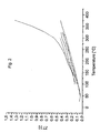
- Fig. 1a , fig. 1b and fig. 2 show the effect of thermal cycling of a Zn 4 Sb 3 material on the Seebeck coefficient, S, the electrical conductivity, ⁇ , and ZT-values respectively.
- the material was thermally cycled within the temperature range of 50 - 350 °C. It can be seen that when the material has been thermally cycled a few times, somewhat stable values are obtained.
- Fig. 1a the lower curve corresponds to the first part of the heating cycle
- Fig. 1b the upper curve corresponds to the first part of the heating cycle.
- the curves represent from top to bottom: first heating cycle, first cooling cycle, second heating cycle, third heating cycle, second cooling cycle, third cooling cycle.
- Fig. 15 shows the physical properties of a zone refined Zn 4 Sb 3 material according to the present invention prior to thermal cycling.
- the sample subjected to zone refinement was made by a process in analogy with the prior art quench method.
- Fig. 15 shows that a figure of merit of above 1.1 can be obtained at approximately 400°C and
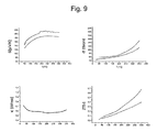
- Fig. 9 shows the physical properties of a zone refined Zn 4 Sb 3 material according to the present invention (upper curve) after thermal cycling.
- Fig. 9 shows that a figure of merit of approximately 0.675 can be obtained at approximately 350°C.
- thermoelectric materials The high degree of phase purity of the inventive thermoelectric materials has been confirmed by the above-mentioned spatial Seebeck microprobe scanning method (or spatial Seebeck scan for short) which is further described below.
- thermoelectric material S is defined as dV/dT, wherein dV is the potential difference present on the material, and dT is the temperature difference present at the position of the material and that the Seebeck-value accordingly is related to the ability of a thermoelectric material to produce a potential difference when arranged in a temperature gradient, it is implied that a useful thermoelectric material must have a high S-value.
- thermoelectric material In a spatial Seebeck scanning method a cross-section of the thermoelectric material is scanned so as to obtain specific Seebeck-values for very small areas of the cross-section of the material.
- the distribution of Seebeck-values - i.e. by plotting the number of times a specific Seebeck-value is measured as a function of each specific Seebeck-value - the phase purity can be visualised.
- the obtained curve shows a single, sharp peak a vast majority of each small scanned area exhibits nearly the same Seebeck-value which is indicative of a high phase purity. If, on the other hand, the curve shows two or more peaks and/or if each peak is not very sharp, the scanned area of the thermoelectric material seems to be not very homogeneous as to the distribution of Seebeck-values, which is indicative of a high degree of phase impurity.
- a spatial Seebeck scan may be an easy way to assess on a preliminary basis the quality of a thermoelectric material in terms of Seebeck-values, and it has been found that the inventive thermoelectric materials according to the present invention which are manufactured by the zone melting process according to the present invention exhibit a single, sharp peak in a spatial Seebeck scan having a homogeneity of 15 ⁇ VK -1 or less as expressed by the width, w of the peak at maximum S/ ⁇ e.
- thermoelectric materials according to the present invention which are manufactured by the zone melting process according to the present invention has improved behaviour in terms of reduction or "loss" of ZT-value during thermal cycling, as compared to thermoelectric materials which has not been made by a zone melting process.
- Fig. 9 shows physical data measured on a Zn 4 Sb 3 material which has not been zone refined (a quenched material made by a process in analogy to the prior art quench method); and a zone refined Zn 4 Sb 3 material according to the present invention respectively.
- the upper curve corresponds to the zone refined material. Both samples have been thermally cycled until constant values of properties were obtained. In respect of the thermal conductivity measurements the two curves are essentially superimposed.
- Fig. 9 shows that zone refining enhances the figure of merit, ZT. At 350 °C the ZT-value is increased from 0.4 without zone refining to 0.675 when zone refined. This corresponds to an increase of approximately 68%.
- the distribution of Seebeck-values, as obtained by a spatial Seebeck scan may in fact be utilised as a qualitative measure of the phase purity of the material. Accordingly, the distribution of the Seebeck-values in the Seebeck scan can be used for defining a given material.
- the inventive thermoelectric materials according to the present invention which are manufactured by the zone melting process according to the present invention exhibit a single, sharp peak in a spatial Seebeck scan having a homogeneity of 15 ⁇ VK -1 or less as expressed by the width, w of the peak at maximum S/ ⁇ e.
- the inventive thermoelectric materials exhibit a single peak corresponding to S > 90 ⁇ VK -1 .
- corresponding to S > 90 ⁇ VK -1 it is understood that the top of the single peak corresponds to a value of S of not less than 90 ⁇ VK -1 in a spatial Seebeck microprobe scan.
- the inventive thermoelectric materials exhibit a single peak corresponding to S > 100 ⁇ VK -1 , such as S > 110 ⁇ VK -1 .
- Fig. 5 visualises the phase purity of a zone refined Zn 4 Sb 3 material according to the present invention.
- the sample was scanned along the lengthwise direction.
- the curve in the upper part of Fig. 5 shows the distribution of Seebeck values in respect of specific values measured, and in the plot in the lower part of Fig. 5 the distribution is visualised by way of shade plotting; each shade corresponds to a specific S value.
- the homogeneity as expressed by the width, w was found to be13.7 ⁇ VK -1 .
- Fig. 6 visualises the phase purity of a zone refined Zn 4 Sb 3 material doped with 1% Mg according to the present invention.
- the sample was scanned along the lengthwise direction.
- the homogeneity as expressed by the width, w was found to be 5.7 ⁇ VK -1 .
- Fig. 10 visualises the phase purity of a quenched Zn 4 Sb 3 material doped with 0.1% Cd according to the present invention. The sample was scanned along the lengthwise direction. The homogeneity as expressed by the width w was found to be 6.7 ⁇ VK -1 .
- the Seebeck coefficient is an indirect measure for charge carrier concentration and thus gives information about the components of the investigated material.
- a scanning Seebeck micro-thermoprobe is a device for measuring the Seebeck coefficient on a sample's surface spatially resolved, and as explained above this provides information as to the homogeneity or distribution of the components.
- microprobe for use in a spatial Seebeck scan is explained below.
- a sample is divided into two halves by cutting the sample in e.g. a lengthwise direction using a diamond wire saw.
- a heated probe tip (50) is positioned onto the surface of a sample (30), which due to the cutting is exposed.
- the probe is connected with a thermocouple (40) (in this case a Cu-CuNi type) measuring the temperature T 1 .
- the sample is in good electrical and thermal contact with a heat sink (20) and also connected with a thermocouple measuring To.
- the probe tip (50) heats the sample in the vicinity of the tip leading to a temperature gradient.
- Tip (50) as well as heat sink (20) is temperature controlled and can be moved via linear stages.
- a major prerequisite of the measuring principle is to keep a temperature gradient between the probe and the sample.
- a suitable value for the gradient turns out to be around 3 K.
- thermocouple Three linear stages are used to scan the surface in the x-y plane (10) of the sample with a physically limited resolution of up to 10 ⁇ m depending on the thermal conductivity of the scanned material.
- the sample must have good thermal contact to the thermocouple and a heat sink. In this case it is embedded into a low melting solder (Wood-metal) with the thermocouple.
- the Seebeck measurements may depend on the calibration of a given apparatus, and thus the absolute values may vary, the relative values of the Seebeck coefficients measured for different samples on the same equipment are reliable.
- the width, w of the peak of the Seebeck scan may be used as a parameter for defining the phase purity, it is desirably that, the obtained width, w is not instrument-dependent. In fact, it has turned out, that the empirically obtained width, w will show little dependence on the exact calibration of the instrument. In other words the width w is independent on the exact absolute values measured for a given apparatus - it represents a distribution of values.
- thermocouples Pt/PtRh
- One side of the sample is contacted with a heat sink so that a temperature gradient is created. This temperature gradient leads to the measured thermopower U(T). Derivating U(T) to the temperature gives the Seebeck coefficient at the temperature T.
- the thermopower was measured in a range of different temperatures.
- a rectangular sample was placed into an oven and contacted at both opposite faces with an AC current source. One side perpendicular to these contacts is contacted with two potential probes of tungsten carbide. The measured voltage is proportional to the electrical conductivity and the current applied to the sample and a geometrical correction factor. The voltage thus giving the electrical conductivity was measured in a range of different temperatures.
- ⁇ was measured with a commercial laser flash apparatus
- C p was measured with a commercial DSC (differential scanning calorimeter) and the density results from the weight and the geometric dimensions.
- thermoelectric materials are manufactured by Processes for the manufacture of the inventive thermoelectric materials
- thermoelectric materials according to the present invention were manufactured by a zone melting process.
- the interphase is preferably provided in the form of a rod of the "non-stoichiometric" material, and a “feeding rod” comprising a thermoelectric material having the stoichiometric formula which is desired for the final thermoelectric product.
- a feeding rod comprising a thermoelectric material having the stoichiometric formula which is desired for the final thermoelectric product.
- the arrangement is obtained by arranging one of the materials on top of the other.
- rod is to be interpreted as any kind of geometrical shape which is suitable for the intended purpose, i.e. suitable for forming either the "non-stoichiometric” or the “stoichiometric” material to be melted in the zone refining process according to the present invention.
- the interphase between the two types of material is subjected to a zone melting, for example by placing this arrangement in the centre of an induction furnace. It is however preferred first to enclose the arrangement in a vacuum. This is preferably achieved by placing the arrangement in an enclosure, such as a quarts tube which subsequently preferably is evacuated and closed by melting its ends, thereby forming an ampoule.
- the "non-stoichiometric" material is surrounded by two "feeding rods" thereby forming two interphases between different materials.
- the lower "feeding rod" simply acts as a support for the arrangement.
- the zone melting is started by applying power to the furnace so that the heat produced at a position corresponding to the interphase between the "non-stoichiometric" material and one feeding rod melts the material of said interphase.
- the power is slightly lowered, e.g. over a time span of approximately 10 min.
- the ampoule is moved through the heating zone of the furnace at a very low speed, such as 0.6 - 1.8 mm/h. In this way the melting zone travels through the material at the same speed.
- the power is switched off and the arrangement is allowed to cool.
- HUP hot uniaxial press
- thermoelectric materials have been consolidated to obtain the most suitable pressure, temperature and duration, which was found to be 100 MPa, 370 °C and 30 min. under an inert atmosphere of 500 hPa nitrogen. All materials were ball-milled in hexane and hot pressed under vacuum. It has turned out that variations in the hot pressing parameters may account for variations in the quality of the resulting thermoelectric materials.
- Zinc powder - if added - was admixed in an amount of 1.2 atom% with the crushed Zn 4 Sb 3 sample and this mixture was then ball-milled (300 rpm) in hexane for one hour and subsequently subjected to the HUP pressing using the above parameters.
- Fig. 12 shows the figure of merit of thermally cycled Zn 4 Sb 3 materials.
- Zone refining improves the properties of a quenched (curve 1b) sample.
- Addition of zinc prior to the HUP (curve 2b) further increases the figure of merit.
- the size of the final samples was varied between 16 mm in diameter and 1 mm in thickness for thermoelectric measurements and evaluation and 4 mm in diameter and 3-5 mm in thickness for the module preparation. Also samples with 16 mm diameter and 3 mm thickness have been prepared for module fabrication. However, the cutting of the samples may be difficult due to the brittleness of the material. 4 mm diameter samples can be used directly for the module.
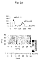
- FIG. 3a , 3b , 4 , 5 , 7 , 8 and 14 The importance of the choice of pulling speed in the zone refining method according to the present invention are illustrated by Fig. 3a , 3b , 4 , 5 , 7 , 8 and 14 :
- fig. 4 shows the phase purity of a zone refined Zn 4 Sb 3 material in which the pulling speed during zone refinement was too low.
- fig. 5 shows the phase purity of a zone refined Zn 4 Sb 3 material in which the pulling speed during zone refinement was correct (1.2 mm/hour).
- the sample was scanned along the lengthwise direction.
- the sample has a purity as expressed by the width, w of the peak at maximum S/ ⁇ e of 13.7 ⁇ VK -1 .
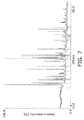
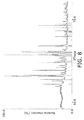
- Fig. 7 and fig. 8 are x-ray powder diffraction diagrams of zone refined Zn 4 Sb 3 materials in which the pulling speed during zone refinement was too high and too low respectively (the continuous spectrum shows the measured data).
- the lines in the diagram correspond to the ZnSb impurity phase implying that too high and too low pulling speeds respectively in the zone refining methods result in ZnSb-phases in the final material.
- fig. 14 is an x-ray powder diffraction diagram of a zone refined Zn 4 Sb 3 material in which the pulling speed during zone refinement was correct (the continuous spectrum shows the measured data).
- the lines in the diagram correspond to the Zn 4 Sb 3 phase, and correspondence between the lines and the continuous spectrum suggests that a correct pulling speed in the zone refining method results in the correct Zn 4 Sb 3 phase in the final material.
- the sample of fig. 14 was made by a process in analogy with the prior art quench method follwed by zone refinement and hot pressing.
- the "feeding rods" for use in the zone melting process may be obtained by a simple thermal quench process in analogy with the prior art quench method (cf. Caillat et al., J. Phys. Chem. Solids, Vol. 58, No 7, pp. 1119 -1125, 1997 ).
- Zn pellets, Sb and optionally substituents selected from the group comprising Mg, Sn, Pb and the transition metals
- the desired mutual molar ratio i.e. the ratio which is desired for the final thermoelectric material
- the Zn pellets prior to mixing with the other components are rinsed in dilute acid, such as dilute HCL, for example 4 M HCl, whereafter they preferably are rinsed in water followed by ethanol and dried with e.g. a hair dryer.
- the tube is evacuated and closed by melting, thereby resulting in a quarts ampoule.
- the tube is evacuated to a final pressure of 10 -5 - 10 -3 bar or less.
- the obtained ampoule is then placed in a rotation device inside a furnace, such as a tube furnace.
- the furnace is switched on, and the ampoule is rotated so as to ensure mixing and homogenous heating.
- the ampoule is heated from room temperature to approximately 700 °C at 200 - 400 °C/h. After a few hours, such as 1 - 3 hours, preferably 2 hours at this temperature, the ampoule is quickly placed in a vessel containing water for thermal quenching.
- thermoelectric materials are obtained which exhibit excellent properties in terms of ZT-values and phase purity as expressed by the spatial Seebeck microprobe scanning, even without the zone melting process, which however will further improve the properties of these materials.
- undoped Zn 4 Sb 3 material albeit this material when not zone refined exhibits a smaller degree of phase purity compared to the doped materials.
- such "quenched" materials has the stoichiometric formula Zn 4 Sb 3 , wherein part of the Zn atoms optionally being substituted by one or more elements selected from the group comprising Mg and Pb in a total amount of 20 mol% or less in relation to the Zn atoms
- Fig. 13 is an x-ray powder diffraction diagram of a quenched Zn 4 Sb 3 material which has not been zone refined (the continuous spectrum shows the measured data).
- the lines in the diagram correspond to the Zn 4 Sb 3 phase and the correspondence between the lines and the continuous spectrum suggests that although the sample has not been zone refined it nevertheless comprises the correct Zn 4 Sb 3 phase.
- Fig. 9 shows the effect on physical properties of zone refining (upper curve) and a quenched Zn 4 Sb 3 material made by a process in analogy with the prior art quench method. (lower curve). Both samples have been thermally cycled until constant values of properties were obtained. In respect of the thermal conductivity measurements the two curves are essentially superimposed. It is seen that zone refining process improves the thermoelectric properties of the material.
- Fig. 10 shows the phase purity of a quenched Zn 4 Sb 3 material which has been doped with 0.1 mol% cadmium. The sample was scanned along the lengthwise direction. Even though this material had not been zone refined, it exhibits excellent phase purity as evidenced by a width, w of 6.7 ⁇ VK -1 .
- fig. 11 shows the phase purity of a quenched Zn 4 Sb 3 material which has been doped with 0.1 mol% magnesium. The sample was scanned along the lengthwise direction. Even though this material had not been zone refined, it exhibits an excellent phase purity expressed by the width, w of 12.0 ⁇ VK -1 .
- the "non-stoichiometric" materials may be obtained by mixing the appropriate amounts of Zn and Sb respectively, then placing this mixture in an enclosure, such as a quartz tube, evacuating and closing said enclosure thereby forming an ampoule and placing the obtained ampoule in a furnace, such as a tube furnace, whereafter the material is sintered.
- an enclosure such as a quartz tube
- evacuating and closing said enclosure thereby forming an ampoule and placing the obtained ampoule in a furnace, such as a tube furnace, whereafter the material is sintered.
- the mixing of the components is preferably performed by rotating the component Zn and Sb in a flask for approximately 1 hour.
- the mixture is sintered for approximately six hours. More preferred the material is sintered for more than approximately 12 hours. It appears that a longer sintering time results in a better mechanical stability of the "non-stoichiometric" material.
- the sintering temperature is suitably selected in the range of 400 - 550 °C, such as approximately 400 - 450 °C.
- the molar ratio Zn to Sb for the "non-stoichiometric" composition is preferably in the range 57:43 to 51:49, such as 56:44 to 52:48, for example 55:45 to 53:47 such as 54:46.
- the most preferred molar ratio Zn to Sb for the "non-stoichiometric" composition is approximately 52:48.
- the enclosure containing the "non-stoichiometric" composition is preferably evaporated to a final pressure of 10 -5 - 10 -3 bar or less.
- thermoelectric materials according to the present invention exhibit an easy and time efficient way to the manufacture of the improved thermoelectric materials according to the present invention.
- inventive materials having the Zn 4 Sb 3 type structure exhibit a single, sharp peak indicating a high degree of phase purity (cf. fig. 5 , fig. 6 , fig. 10 and fig. 11 .
- thermoelectric materials according to the present invention exhibiting a single peak in said spatial Seebeck scanning have been shown to have a Zn 4 Sb 3 type structure (cf. fig 13 , fig. 14 and fig. 16 ),
- fig. 12 and 15 the thermoelectric materials according to the present invention have excellent thermoelectric properties.
- thermoelectric materials of the p-type having the stoichiometric formula Zn 4 Sb 3 wherein part of the Zn atoms optionally being substituted by one or more elements selected from the group comprising Sn, Mg, Pb and the transition metals in a total amount of 20 mol% or less in relation to the Zn atoms according to the present invention prior to thermal cycling have a ZT at 375 °C of 1.3 or more, such as 1.4 or more, for example 1.5 or more; or 1.6 or more, such as 1.7 or more.
- thermoelectric material of the above type having the stoichiometric formula Zn 4 Sb 3 according to the present invention prior to thermal cycling preferably have a ZT at 400 °C of 1.4 or more, such as 1.5 or more, for example 1.6 or more, such as 1.7 or more.
- thermoelectric materials of the p-type having the stoichiometric formula Zn 4 Sb 3 wherein part of the Zn atoms optionally being substituted by one or more elements selected from the group comprising Sn, Mg, Pb and the transition metals in a total amount of 20 mol% or less in relation to the Zn atoms according to the present invention preferably have a ZT at 350 °C of 0.4 or more, such as 0.5 or more, for example 0.6 or more, such as 0.7 or more; or 0.8 or more, such as 0.9 or more, e.g. 1.0 or more.
- thermoelectric materials of the p-type having the stoichiometric formula Zn 4 Sb 3 , wherein part of the Zn atoms optionally being substituted by one or more elements selected from the group comprising Sn, Mg, Pb and the transition metals in a total amount of 20 mol% or less in relation to the Zn atoms according to the present invention after thermal cycling preferably have a ZT at 400 °C of 0.5 or more, such as 0.6 or more, for example 0.7 or more, such as 0.8 or more; or 0.9 or more, such as 1.0 or more, e.g. 1.1 or 1.2 or more; for example 1.3 or more, such as 1.4 or more.
- the zone melting process may be applied in the phase refining of an already existing thermoelectric material showing a peritectic reaction analogue to Zn 4 Sb 3 .
- the zone melting process may also be applied in situations in which an improved purity of an already existing thermoelectric material is desired.
- the already existing thermoelectric material is simply used as "feeding rod(s)" as generally described above and the already existing thermoelectric material is then subjected to the zone refining process.
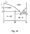
- Fig. 18 shows a phase diagram of a material having a binary composition (of element A and element B) and showing a peritectic reaction analogue to Zn 4 Sb 3 .
- the x-axis represents the composition ranging (from left to right) from pure A to pure B.
- the y-axis represent the temperature.
- composition of the material of the "non-stoichiometric" rod should be selected so as to correspond to the projection of the liquidus curve "x-m" of fig. 18 on the composition axis (the x-axis).
- thermoelectric material is a tertiary material (a material composed of three elements)
- the phase diagram is three-dimensional, and the projection of the liquidus curve "x-m" will be a two-dimensional surface, etc.
- thermoelectric material showing a peritectic reaction
- the zone melting process according to the present invention is performed on an already existing thermoelectric material having the composition CoSb 3 or FeSb 2 .
- the phase diagram of these thermoelectric materials can be found in M. Hansen, "The constitution of binary alloys", McGraw-Hill Book Company, New York, 1958 ; and R. D. Elliot, ""The constitution of binary alloys, first supplement", McGraw-Hill, Inc. New York, 1965 .
- thermoelectric material is used as the p-type thermoelectric in a thermocouple.
- a thermocouple is obtained in a way known per se. See for example “ Frank Benhard; Technische Temperaturtechnik; Springer Berlin, 2003; ISBN 3540626727 ".
- thermocouples In a special embodiment according to the present invention one or more of the obtained thermocouples is/are arranged in a way known per se in order to obtain a thermoelectric device. See for example “ Frank Benhard; Technische Temperaturtechnik; Springer Berlin, 2003; ISBN 3540626727 ".
- thermoelectric Device for thermoelectric purposes
- thermoelectric device is used for thermoelectric purposes.
- thermoelectrics Such uses are well-known for a person skilled in the art of thermoelectrics.
- This ampoule was placed in a rotation device inside a tube furnace (HEREUS, ROK/A 6/30), and it was rotated consistently during heating so as to ensure mixing and homogenous heating. It was heated from room temperature to 700 °C at 400 °C/h. After 2 hours the ampoule was quickly placed in a water container for thermal quenching, thereby obtaining a rod.
- HEREUS a rotation device inside a tube furnace
- ROK/A 6/30 ROK/A 6/30
- Fig. 9 shows physical data measured on the Zn 4 Sb 3 material which has not been zone refined (the quenched material) - the lower curve. The sample has been thermally cycled until constant values of properties were obtained.
- Fig. 13 is an x-ray powder diffraction diagram of quenched Zn 4 Sb 3 material (the continuous spectrum shows the measured data).
- the lines in the diagram correspond to the Zn 4 Sb 3 phase and correspondence between the lines and the continuous spectrum suggests that it comprises the correct Zn 4 Sb 3 phase.
- thermoelectric material a 2% Mg-doped thermoelectric material is obtained.
- a 0.1 % Mg doped Zn 4 Sb 3 material was made.
- Fig. 11 shows the phase purity of this thermoelectric material expressed by the distribution of Seebeck values. The sample was scanned along the lengthwise direction. Even though this material had not been zone refined, it exhibits a phase purity expressed by w of 12.0 ⁇ VK -1 .
- thermoelectric material a 1% Cd-doped thermoelectric material is obtained.
- a 0.1 % Cd doped Zn 4 Sb 3 material was made.
- Fig. 10 shows the phase purity of this thermoelectric material expressed by the distribution of Seebeck values. The sample was scanned along the lengthwise direction. Even though this material had not been zone refined, it exhibits a phase purity expressed by w of 6.7 ⁇ VK -1 .
- thermoelectric material is obtained.
- thermoelectric material a Pb-doped thermoelectric material is obtained.
- thermoelectric material a Sn-doped thermoelectric material is obtained.
- thermoelectric material a Mg- and Cd-doped thermoelectric material is obtained.
- a quartz tube designed for mounting in an induction furnace 18 mm of a rod obtained in example 1 (a "feeding rod") was placed at the bottom.
- a 10 mm piece of the sintered "non-stoichiometric" material obtained as described above was placed on top.
- a large “feeding rod”, 70 mm, also prepared according to example 1 was placed on top of the "non-stoichiometric” rod.
- the quartz tube was closed by melting a piece of glass at the upper part, which allows mounting on a vacuum pump.
- the tube was evacuated to 10 -5 bar and closed by melting.
- the quartz ampoule was placed in a boron nitride (BN) holder at the bottom of the induction furnace (TSS model HP crystal growing furnace, 60kW max power).
- BN boron nitride
- the top of the ampoule was fastened inside another BN mount, which was screwed into the pulling stick of the furnace.
- the ampoule was placed with the induction coil positioned around the "non-stoichiometric" rod, i.e. this is where the melt zone starts.
- the coil had three "windings" or coils in an overall conical shape.
- the top was 38 mm wide, the bottom 20 mm wide. Each coil was 5 mm thick. Heating was started and melting was observed in about 15 min., and the power was lowered slightly over 10 minutes.
- the power input was approximately 3.5 kW (2.5 kV, 1.4 A). After another 10 minutes the ampoule was pulled through the induction coils at a rate of 1.2 mm per hour.
- zone-refined Zn 4 Sb 3 material was ball-milled under hexane and hot pressed at 100 MPa, 370 °C and 30 min. under an inert atmosphere of 500 hPa nitrogen.
- Fig. 5 shows the phase purity of this thermoelectric material expressed by the distribution of Seebeck values. The sample was scanned along the lengthwise direction. The material exhibits a phase purity expressed by w of 13.7 ⁇ VK -1 .
- Fig. 15 shows physical data measured on the Zn 4 Sb 3 material which has been zone refined The measurements took place before thermally cycling. At approximately 400 °C the ZT-value is above 1.1.
- Fig. 9 shows physical data measured on a Zn 4 Sb 3 material which has not been zone refined (a quenched material); and a zone refined Zn 4 Sb 3 material according to the present invention respectively.
- the upper curve corresponds to the zone refined material. Both samples have been thermally cycled until constant values of properties were obtained. In respect of the thermal conductivity measurements the two curves are essentially superimposed.
- Fig. 9 shows that zone refining enhances the figure of merit, ZT. At 350 °C the ZT-value is increased from 0.4 without zone refining to 0.675 when zone refined which corresponds to an increase of approximately 68%.
- Fig. 14 is an x-ray powder diffraction diagram of the zone refined Zn 4 Sb 3 material (the continuous spectrum shows the measured data).
- the lines in the diagram correspond to the Zn 4 Sb 3 phase and correspondence between the lines and the continuous spectrum suggests it comprises the correct Zn 4 Sb 3 phase.
- Fig. 6 shows the phase purity of this thermoelectric material expressed by the distribution of Seebeck values. The sample was scanned along the lengthwise direction. The thermoelectric material exhibits a phase purity expressed by w of 5.7 ⁇ VK -1 .
- Fig 16 is an x-ray powder diffraction diagram of the zone refined Mg-doped Zn 4 Sb 3 material (the continuous spectrum shows the measured data). The lines in the diagram correspond to the Zn 4 Sb 3 phase and correspondence between the lines and the continuous spectrum suggests it comprises the correct Zn 4 Sb 3 phase.
Landscapes
- Chemical & Material Sciences (AREA)
- Engineering & Computer Science (AREA)
- Materials Engineering (AREA)
- Mechanical Engineering (AREA)
- Metallurgy (AREA)
- Organic Chemistry (AREA)
- Physics & Mathematics (AREA)
- Thermal Sciences (AREA)
- Crystallography & Structural Chemistry (AREA)
- Inorganic Chemistry (AREA)
- Powder Metallurgy (AREA)
- Inorganic Compounds Of Heavy Metals (AREA)
- Silicon Compounds (AREA)
Priority Applications (1)
| Application Number | Priority Date | Filing Date | Title |
|---|---|---|---|
| EP10186169.8A EP2325344B1 (de) | 2005-05-31 | 2006-05-31 | Verbesserte Thermoelektrische Materiale des p-Typs, Verfahren zur Herstellung und Verwendung derselben |
Applications Claiming Priority (4)
| Application Number | Priority Date | Filing Date | Title |
|---|---|---|---|
| EP05011707A EP1728880A1 (de) | 2005-05-31 | 2005-05-31 | Verbesserte Thermoelektrische Materiale des n-Typs, Verfahren zur Herstellung und Verwendung derselben |
| US68624005P | 2005-06-01 | 2005-06-01 | |
| EP06753298.6A EP1885896B1 (de) | 2005-05-31 | 2006-05-31 | Herstellungsverfahren für verbesserte thermoelektrische materialien vom p-typ und verwendungen davon |
| EP10186169.8A EP2325344B1 (de) | 2005-05-31 | 2006-05-31 | Verbesserte Thermoelektrische Materiale des p-Typs, Verfahren zur Herstellung und Verwendung derselben |
Related Parent Applications (3)
| Application Number | Title | Priority Date | Filing Date |
|---|---|---|---|
| EP06753298.6A Division EP1885896B1 (de) | 2005-05-31 | 2006-05-31 | Herstellungsverfahren für verbesserte thermoelektrische materialien vom p-typ und verwendungen davon |
| EP06753298.6A Division-Into EP1885896B1 (de) | 2005-05-31 | 2006-05-31 | Herstellungsverfahren für verbesserte thermoelektrische materialien vom p-typ und verwendungen davon |
| EP06753298.6 Division | 2006-05-31 |
Publications (3)
| Publication Number | Publication Date |
|---|---|
| EP2325344A2 true EP2325344A2 (de) | 2011-05-25 |
| EP2325344A3 EP2325344A3 (de) | 2011-08-24 |
| EP2325344B1 EP2325344B1 (de) | 2016-12-07 |
Family
ID=34937086
Family Applications (3)
| Application Number | Title | Priority Date | Filing Date |
|---|---|---|---|
| EP05011707A Withdrawn EP1728880A1 (de) | 2005-05-31 | 2005-05-31 | Verbesserte Thermoelektrische Materiale des n-Typs, Verfahren zur Herstellung und Verwendung derselben |
| EP10186169.8A Not-in-force EP2325344B1 (de) | 2005-05-31 | 2006-05-31 | Verbesserte Thermoelektrische Materiale des p-Typs, Verfahren zur Herstellung und Verwendung derselben |
| EP06753298.6A Not-in-force EP1885896B1 (de) | 2005-05-31 | 2006-05-31 | Herstellungsverfahren für verbesserte thermoelektrische materialien vom p-typ und verwendungen davon |
Family Applications Before (1)
| Application Number | Title | Priority Date | Filing Date |
|---|---|---|---|
| EP05011707A Withdrawn EP1728880A1 (de) | 2005-05-31 | 2005-05-31 | Verbesserte Thermoelektrische Materiale des n-Typs, Verfahren zur Herstellung und Verwendung derselben |
Family Applications After (1)
| Application Number | Title | Priority Date | Filing Date |
|---|---|---|---|
| EP06753298.6A Not-in-force EP1885896B1 (de) | 2005-05-31 | 2006-05-31 | Herstellungsverfahren für verbesserte thermoelektrische materialien vom p-typ und verwendungen davon |
Country Status (6)
| Country | Link |
|---|---|
| US (2) | US8003002B2 (de) |
| EP (3) | EP1728880A1 (de) |
| DK (1) | DK1885896T3 (de) |
| ES (1) | ES2494841T3 (de) |
| PL (1) | PL1885896T3 (de) |
| WO (1) | WO2006128467A2 (de) |
Cited By (1)
| Publication number | Priority date | Publication date | Assignee | Title |
|---|---|---|---|---|
| TWI417248B (zh) * | 2011-12-23 | 2013-12-01 | 財團法人工業技術研究院 | 熱電材料與其製造方法、以及包含其熱電模組 |
Families Citing this family (13)
| Publication number | Priority date | Publication date | Assignee | Title |
|---|---|---|---|---|
| US7622523B2 (en) | 2002-08-12 | 2009-11-24 | Exxonmobil Chemical Patents Inc. | Plasticized polyolefin compositions |
| CN100345896C (zh) | 2002-08-12 | 2007-10-31 | 埃克森美孚化学专利公司 | 增塑聚烯烃组合物 |
| EP1728880A1 (de) * | 2005-05-31 | 2006-12-06 | Aarhus Universitet | Verbesserte Thermoelektrische Materiale des n-Typs, Verfahren zur Herstellung und Verwendung derselben |
| EP2625728A1 (de) | 2010-10-05 | 2013-08-14 | Aarhus Universitet | Stabile thermoelektrische vorrichtungen |
| CN105431561A (zh) * | 2011-07-15 | 2016-03-23 | 奥胡斯大学 | 生产热电固体元件的方法 |
| ES2380966B1 (es) * | 2011-10-14 | 2013-04-03 | La Farga Lacambra, S.A. | Dispositivo generador de potencia electrica |
| KR20130098605A (ko) * | 2012-02-28 | 2013-09-05 | 한국전기연구원 | Mn이 도핑된 Zn₄Sb₃계 열전재료의 제조방법 및 그 열전재료 |
| US10062825B2 (en) * | 2012-06-28 | 2018-08-28 | City University Of Hong Kong | Thermo-electric generator module |
| ES2397775B1 (es) * | 2012-11-16 | 2013-09-27 | La Farga Lacambra, S.A. | Procedimiento de obtención de aleaciones Zn-Sb con propiedades termoeléctricas |
| CN104419977A (zh) * | 2013-09-07 | 2015-03-18 | 云南师范大学 | 一种β-Zn4Sb3单晶热电材料的制备方法 |
| CN105047809B (zh) * | 2015-06-30 | 2018-06-05 | 中国科学院宁波材料技术与工程研究所 | SnSe基热电材料及其制备方法 |
| CN109402434B (zh) * | 2018-10-26 | 2021-05-04 | 武汉理工大学 | 一种超快速制备ZnSb化合物的方法 |
| CN112342618B (zh) * | 2020-09-30 | 2021-09-28 | 浙江先导热电科技股份有限公司 | 一种提高碲化铋基区熔铸锭热电性能均匀性的方法 |
Citations (1)
| Publication number | Priority date | Publication date | Assignee | Title |
|---|---|---|---|---|
| US6458319B1 (en) | 1997-03-18 | 2002-10-01 | California Institute Of Technology | High performance P-type thermoelectric materials and methods of preparation |
Family Cites Families (7)
| Publication number | Priority date | Publication date | Assignee | Title |
|---|---|---|---|---|
| US3021378A (en) * | 1959-03-21 | 1962-02-13 | Siemens Ag | Method for producing theremoelectric components on zinc-antimony basis |
| US3086068A (en) * | 1959-06-10 | 1963-04-16 | Westinghouse Electric Corp | Process for the preparation of thermo-electric elements |
| WO2002089224A1 (en) * | 2001-05-01 | 2002-11-07 | California Institute Of Technology | Thermoelectric unicouple used for power generation |
| JP3704556B2 (ja) * | 2001-10-29 | 2005-10-12 | 独立行政法人産業技術総合研究所 | 亜鉛アンチモン化合物の製造法 |
| JP4341440B2 (ja) * | 2003-05-21 | 2009-10-07 | 宇部興産株式会社 | 熱電変換材料 |
| DE102004025065A1 (de) * | 2004-05-18 | 2005-12-08 | Basf Ag | Antimonide mit neuen Eigenschaftskombinationen |
| EP1728880A1 (de) * | 2005-05-31 | 2006-12-06 | Aarhus Universitet | Verbesserte Thermoelektrische Materiale des n-Typs, Verfahren zur Herstellung und Verwendung derselben |
-
2005
- 2005-05-31 EP EP05011707A patent/EP1728880A1/de not_active Withdrawn
-
2006
- 2006-05-31 PL PL06753298T patent/PL1885896T3/pl unknown
- 2006-05-31 US US11/921,347 patent/US8003002B2/en active Active
- 2006-05-31 EP EP10186169.8A patent/EP2325344B1/de not_active Not-in-force
- 2006-05-31 ES ES06753298.6T patent/ES2494841T3/es active Active
- 2006-05-31 WO PCT/DK2006/000305 patent/WO2006128467A2/en not_active Ceased
- 2006-05-31 EP EP06753298.6A patent/EP1885896B1/de not_active Not-in-force
- 2006-05-31 DK DK06753298.6T patent/DK1885896T3/da active
-
2011
- 2011-07-13 US US13/182,296 patent/US8524106B2/en active Active
Patent Citations (1)
| Publication number | Priority date | Publication date | Assignee | Title |
|---|---|---|---|---|
| US6458319B1 (en) | 1997-03-18 | 2002-10-01 | California Institute Of Technology | High performance P-type thermoelectric materials and methods of preparation |
Non-Patent Citations (11)
| Title |
|---|
| "Thermoelectric Handbook", 1995, CRC PRESS |
| "Thermoelectrics - Basic Principles and new Materials Developments", 2001, SPRINGER VERLAG |
| CAGLIONI, F.; NISHIBORI, E.; RABILLER, P.; BERTINI, L.; CHRISTENSEN, M.; SNYDER, G. J.; GATTI, C.; IVERSEN, B. B., CHEM. EUR. J., vol. 10, 2004, pages 3861 - 3870 |
| CAILLAT ET AL., J. PHYS. CHEM. SOLIDS, vol. 58, no. 7, 1997, pages 1119 - 1125 |
| L. T. ZHANG ET AL., J. ALLOYS AND COMPOUNDS, vol. 358, 2003, pages 252 - 256 |
| L. T. ZHANG ET AL.: "Effects of ZnSb and Zn inclusions on the thermoelectric properties of O-Zn4Sb3", J. ALLOYS AND COMPOUNDS, vol. 358, 2003, pages 252 - 256, XP004448436, DOI: doi:10.1016/S0925-8388(03)00074-4 |
| M. HANSEN: "The constitution of binary alloys", 1958, MCGRAW-HILL BOOK COMPANY |
| P. REINSHAUS; H. SUL3MANN; M. BOHM; A. SCHUCK; T. DIETRICH: "Proc. of the 2nd European Symposium on Thermoelectrics", MATERIALS, PROCESSING TECHNIQUES AND APPLICATIONS, 1994, pages 90 |
| R. D. ELLIOT: "The constitution of binary alloys, first supplement", 1965, MCGRAW-HILL, INC. |
| SNYDER, G. J.; CHRISTENSEN, M.; NISHIBORI, E.; RABILLER, P.; CAILLAT, T.; IVERSEN, B. B., NATURE MATERIALS, vol. 3, 2004, pages 458 - 463 |
| T. CAILLAT ET AL., J. PHYS. CHEM. SOLIDS, vol. 58, no. 7, 1997, pages 1119J |
Cited By (2)
| Publication number | Priority date | Publication date | Assignee | Title |
|---|---|---|---|---|
| TWI417248B (zh) * | 2011-12-23 | 2013-12-01 | 財團法人工業技術研究院 | 熱電材料與其製造方法、以及包含其熱電模組 |
| US8865997B2 (en) | 2011-12-23 | 2014-10-21 | Industrial Technology Research Institute | Thermoelectric material, method for fabricating the same, and thermoelectric module employing the same |
Also Published As
| Publication number | Publication date |
|---|---|
| EP2325344B1 (de) | 2016-12-07 |
| PL1885896T3 (pl) | 2015-02-27 |
| WO2006128467A3 (en) | 2007-07-19 |
| US8003002B2 (en) | 2011-08-23 |
| WO2006128467A2 (en) | 2006-12-07 |
| US20090229647A1 (en) | 2009-09-17 |
| EP1885896A2 (de) | 2008-02-13 |
| EP1728880A1 (de) | 2006-12-06 |
| US8524106B2 (en) | 2013-09-03 |
| DK1885896T3 (da) | 2014-08-25 |
| US20110297872A1 (en) | 2011-12-08 |
| EP2325344A3 (de) | 2011-08-24 |
| EP1885896B1 (de) | 2014-05-21 |
| ES2494841T3 (es) | 2014-09-16 |
Similar Documents
| Publication | Publication Date | Title |
|---|---|---|
| US8524106B2 (en) | P-type thermoelectric materials, a process for their manufacture and uses thereof | |
| Liang et al. | Ultra-fast synthesis and thermoelectric properties of Te doped skutterudites | |
| JP5636419B2 (ja) | 自己組織化熱電材料 | |
| EP3017485B1 (de) | Thermoelektrische materialien auf der basis einer tetraedritstruktur für thermoelektrische vorrichtungen | |
| Ur et al. | Solid-state syntheses and properties of Zn4Sb3 thermoelectric materials | |
| Schröder et al. | TAGS-related indium compounds and their thermoelectric properties–the solid solution series (GeTe) x AgIn y Sb 1− y Te 2 (x= 1–12; y= 0.5 and 1) | |
| WO2001017034A1 (en) | Process for producing thermoelectric material and thermoelectric material thereof | |
| JP2007146283A (ja) | マグネシウム、珪素、スズからなる金属間化合物の焼結体およびその製造方法 | |
| Liu et al. | Microstructure and thermoelectric properties of higher manganese silicides fabricated via gas atomization and spark plasma sintering | |
| JP6154836B2 (ja) | 熱電材料、並びにそれを用いた熱電変換素子及び熱電変換モジュール | |
| Dharmaiah et al. | Mechanical and thermoelectric properties of environment friendly higher manganese silicide fabricated using water atomization and spark plasma sintering | |
| Rauscher et al. | Synthesis, structure, and high temperature thermoelectric properties of Yb11Sb9. 3Ge0. 5 | |
| Dadda et al. | Electronic Properties as a Function of Ag/Sb Ratio in Ag1− y Pb18Sb1+ z Te20 Compounds | |
| Simard et al. | Production of thermoelectric materials by mechanical alloying-Extrusion process | |
| Jing et al. | Microstructural analysis and thermoelectric properties of skutterudite CoSb3 materials produced by melt spinning and spark plasma sintering | |
| Wang et al. | Thermoelectric properties of indium-filled skutterudites prepared by combining solvothermal synthesis and melting | |
| US20230284532A1 (en) | Alloy, sintered article, thermoelectric module and method for the production of a sintered article | |
| Uher et al. | Materials with open crystal structure as prospective novel thermoelectrics | |
| US20090208364A1 (en) | Making Thermoelectric Materials by Mechanosynthesis | |
| Sesselmann et al. | The influence of synthesis procedure on the microstructure and thermoelectric properties of p-type skutterudite Ce0. 6Fe2Co2Sb12 | |
| Nolas et al. | Low-temperature transport properties of polycrystalline Ba8Ga16Sn30 | |
| JPH10102160A (ja) | 三アンチモン化コバルト系複合材料の製造方法 | |
| US20160035954A1 (en) | Thermoelectric performance of calcium and calcium-cerium filled n-type skutterudites | |
| JP4296272B2 (ja) | 熱電材料の製造方法 | |
| JP2004296480A (ja) | 熱電変換材料およびその製造方法 |
Legal Events
| Date | Code | Title | Description |
|---|---|---|---|
| PUAI | Public reference made under article 153(3) epc to a published international application that has entered the european phase |
Free format text: ORIGINAL CODE: 0009012 |
|
| AC | Divisional application: reference to earlier application |
Ref document number: 1885896 Country of ref document: EP Kind code of ref document: P |
|
| AK | Designated contracting states |
Kind code of ref document: A2 Designated state(s): AT BE BG CH CY CZ DE DK EE ES FI FR GB GR HU IE IS IT LI LT LU LV MC NL PL PT RO SE SI SK TR |
|
| PUAL | Search report despatched |
Free format text: ORIGINAL CODE: 0009013 |
|
| AK | Designated contracting states |
Kind code of ref document: A3 Designated state(s): AT BE BG CH CY CZ DE DK EE ES FI FR GB GR HU IE IS IT LI LT LU LV MC NL PL PT RO SE SI SK TR |
|
| RIC1 | Information provided on ipc code assigned before grant |
Ipc: C22C 12/00 20060101AFI20110718BHEP Ipc: H01L 35/18 20060101ALI20110718BHEP |
|
| 17P | Request for examination filed |
Effective date: 20120224 |
|
| 17Q | First examination report despatched |
Effective date: 20120925 |
|
| GRAP | Despatch of communication of intention to grant a patent |
Free format text: ORIGINAL CODE: EPIDOSNIGR1 |
|
| RIC1 | Information provided on ipc code assigned before grant |
Ipc: C22F 1/12 20060101ALI20160503BHEP Ipc: C22C 1/05 20060101ALI20160503BHEP Ipc: C22C 12/00 20060101AFI20160503BHEP Ipc: H01L 35/18 20060101ALI20160503BHEP Ipc: C22C 1/04 20060101ALI20160503BHEP |
|
| INTG | Intention to grant announced |
Effective date: 20160524 |
|
| GRAJ | Information related to disapproval of communication of intention to grant by the applicant or resumption of examination proceedings by the epo deleted |
Free format text: ORIGINAL CODE: EPIDOSDIGR1 |
|
| GRAR | Information related to intention to grant a patent recorded |
Free format text: ORIGINAL CODE: EPIDOSNIGR71 |
|
| GRAS | Grant fee paid |
Free format text: ORIGINAL CODE: EPIDOSNIGR3 |
|
| GRAA | (expected) grant |
Free format text: ORIGINAL CODE: 0009210 |
|
| INTC | Intention to grant announced (deleted) | ||
| INTG | Intention to grant announced |
Effective date: 20161025 |
|
| AC | Divisional application: reference to earlier application |
Ref document number: 1885896 Country of ref document: EP Kind code of ref document: P |
|
| AK | Designated contracting states |
Kind code of ref document: B1 Designated state(s): AT BE BG CH CY CZ DE DK EE ES FI FR GB GR HU IE IS IT LI LT LU LV MC NL PL PT RO SE SI SK TR |
|
| REG | Reference to a national code |
Ref country code: GB Ref legal event code: FG4D |
|
| REG | Reference to a national code |
Ref country code: CH Ref legal event code: EP Ref country code: AT Ref legal event code: REF Ref document number: 851782 Country of ref document: AT Kind code of ref document: T Effective date: 20161215 |
|
| REG | Reference to a national code |
Ref country code: IE Ref legal event code: FG4D |
|
| REG | Reference to a national code |
Ref country code: DE Ref legal event code: R096 Ref document number: 602006051191 Country of ref document: DE |
|
| PG25 | Lapsed in a contracting state [announced via postgrant information from national office to epo] |
Ref country code: LV Free format text: LAPSE BECAUSE OF FAILURE TO SUBMIT A TRANSLATION OF THE DESCRIPTION OR TO PAY THE FEE WITHIN THE PRESCRIBED TIME-LIMIT Effective date: 20161207 |
|
| REG | Reference to a national code |
Ref country code: LT Ref legal event code: MG4D |
|
| REG | Reference to a national code |
Ref country code: NL Ref legal event code: MP Effective date: 20161207 |
|
| PG25 | Lapsed in a contracting state [announced via postgrant information from national office to epo] |
Ref country code: LT Free format text: LAPSE BECAUSE OF FAILURE TO SUBMIT A TRANSLATION OF THE DESCRIPTION OR TO PAY THE FEE WITHIN THE PRESCRIBED TIME-LIMIT Effective date: 20161207 Ref country code: GR Free format text: LAPSE BECAUSE OF FAILURE TO SUBMIT A TRANSLATION OF THE DESCRIPTION OR TO PAY THE FEE WITHIN THE PRESCRIBED TIME-LIMIT Effective date: 20170308 Ref country code: SE Free format text: LAPSE BECAUSE OF FAILURE TO SUBMIT A TRANSLATION OF THE DESCRIPTION OR TO PAY THE FEE WITHIN THE PRESCRIBED TIME-LIMIT Effective date: 20161207 |
|
| REG | Reference to a national code |
Ref country code: AT Ref legal event code: MK05 Ref document number: 851782 Country of ref document: AT Kind code of ref document: T Effective date: 20161207 |
|
| PG25 | Lapsed in a contracting state [announced via postgrant information from national office to epo] |
Ref country code: ES Free format text: LAPSE BECAUSE OF FAILURE TO SUBMIT A TRANSLATION OF THE DESCRIPTION OR TO PAY THE FEE WITHIN THE PRESCRIBED TIME-LIMIT Effective date: 20161207 Ref country code: FI Free format text: LAPSE BECAUSE OF FAILURE TO SUBMIT A TRANSLATION OF THE DESCRIPTION OR TO PAY THE FEE WITHIN THE PRESCRIBED TIME-LIMIT Effective date: 20161207 |
|
| PG25 | Lapsed in a contracting state [announced via postgrant information from national office to epo] |
Ref country code: NL Free format text: LAPSE BECAUSE OF FAILURE TO SUBMIT A TRANSLATION OF THE DESCRIPTION OR TO PAY THE FEE WITHIN THE PRESCRIBED TIME-LIMIT Effective date: 20161207 |
|
| PG25 | Lapsed in a contracting state [announced via postgrant information from national office to epo] |
Ref country code: EE Free format text: LAPSE BECAUSE OF FAILURE TO SUBMIT A TRANSLATION OF THE DESCRIPTION OR TO PAY THE FEE WITHIN THE PRESCRIBED TIME-LIMIT Effective date: 20161207 Ref country code: RO Free format text: LAPSE BECAUSE OF FAILURE TO SUBMIT A TRANSLATION OF THE DESCRIPTION OR TO PAY THE FEE WITHIN THE PRESCRIBED TIME-LIMIT Effective date: 20161207 Ref country code: CZ Free format text: LAPSE BECAUSE OF FAILURE TO SUBMIT A TRANSLATION OF THE DESCRIPTION OR TO PAY THE FEE WITHIN THE PRESCRIBED TIME-LIMIT Effective date: 20161207 Ref country code: SK Free format text: LAPSE BECAUSE OF FAILURE TO SUBMIT A TRANSLATION OF THE DESCRIPTION OR TO PAY THE FEE WITHIN THE PRESCRIBED TIME-LIMIT Effective date: 20161207 Ref country code: IS Free format text: LAPSE BECAUSE OF FAILURE TO SUBMIT A TRANSLATION OF THE DESCRIPTION OR TO PAY THE FEE WITHIN THE PRESCRIBED TIME-LIMIT Effective date: 20170407 |
|
| PG25 | Lapsed in a contracting state [announced via postgrant information from national office to epo] |
Ref country code: BG Free format text: LAPSE BECAUSE OF FAILURE TO SUBMIT A TRANSLATION OF THE DESCRIPTION OR TO PAY THE FEE WITHIN THE PRESCRIBED TIME-LIMIT Effective date: 20170307 Ref country code: IT Free format text: LAPSE BECAUSE OF FAILURE TO SUBMIT A TRANSLATION OF THE DESCRIPTION OR TO PAY THE FEE WITHIN THE PRESCRIBED TIME-LIMIT Effective date: 20161207 Ref country code: PL Free format text: LAPSE BECAUSE OF FAILURE TO SUBMIT A TRANSLATION OF THE DESCRIPTION OR TO PAY THE FEE WITHIN THE PRESCRIBED TIME-LIMIT Effective date: 20161207 Ref country code: BE Free format text: LAPSE BECAUSE OF FAILURE TO SUBMIT A TRANSLATION OF THE DESCRIPTION OR TO PAY THE FEE WITHIN THE PRESCRIBED TIME-LIMIT Effective date: 20161207 Ref country code: AT Free format text: LAPSE BECAUSE OF FAILURE TO SUBMIT A TRANSLATION OF THE DESCRIPTION OR TO PAY THE FEE WITHIN THE PRESCRIBED TIME-LIMIT Effective date: 20161207 Ref country code: PT Free format text: LAPSE BECAUSE OF FAILURE TO SUBMIT A TRANSLATION OF THE DESCRIPTION OR TO PAY THE FEE WITHIN THE PRESCRIBED TIME-LIMIT Effective date: 20170407 Ref country code: LU Free format text: LAPSE BECAUSE OF NON-PAYMENT OF DUE FEES Effective date: 20170531 |
|
| REG | Reference to a national code |
Ref country code: DE Ref legal event code: R097 Ref document number: 602006051191 Country of ref document: DE |
|
| PLBE | No opposition filed within time limit |
Free format text: ORIGINAL CODE: 0009261 |
|
| STAA | Information on the status of an ep patent application or granted ep patent |
Free format text: STATUS: NO OPPOSITION FILED WITHIN TIME LIMIT |
|
| 26N | No opposition filed |
Effective date: 20170908 |
|
| PG25 | Lapsed in a contracting state [announced via postgrant information from national office to epo] |
Ref country code: DK Free format text: LAPSE BECAUSE OF FAILURE TO SUBMIT A TRANSLATION OF THE DESCRIPTION OR TO PAY THE FEE WITHIN THE PRESCRIBED TIME-LIMIT Effective date: 20161207 Ref country code: SI Free format text: LAPSE BECAUSE OF FAILURE TO SUBMIT A TRANSLATION OF THE DESCRIPTION OR TO PAY THE FEE WITHIN THE PRESCRIBED TIME-LIMIT Effective date: 20161207 |
|
| REG | Reference to a national code |
Ref country code: DE Ref legal event code: R119 Ref document number: 602006051191 Country of ref document: DE |
|
| REG | Reference to a national code |
Ref country code: CH Ref legal event code: PL |
|
| GBPC | Gb: european patent ceased through non-payment of renewal fee |
Effective date: 20170531 |
|
| PG25 | Lapsed in a contracting state [announced via postgrant information from national office to epo] |
Ref country code: MC Free format text: LAPSE BECAUSE OF FAILURE TO SUBMIT A TRANSLATION OF THE DESCRIPTION OR TO PAY THE FEE WITHIN THE PRESCRIBED TIME-LIMIT Effective date: 20161207 |
|
| REG | Reference to a national code |
Ref country code: IE Ref legal event code: MM4A |
|
| PG25 | Lapsed in a contracting state [announced via postgrant information from national office to epo] |
Ref country code: CH Free format text: LAPSE BECAUSE OF NON-PAYMENT OF DUE FEES Effective date: 20170531 Ref country code: LI Free format text: LAPSE BECAUSE OF NON-PAYMENT OF DUE FEES Effective date: 20170531 |
|
| REG | Reference to a national code |
Ref country code: FR Ref legal event code: ST Effective date: 20180131 |
|
| PG25 | Lapsed in a contracting state [announced via postgrant information from national office to epo] |
Ref country code: GB Free format text: LAPSE BECAUSE OF NON-PAYMENT OF DUE FEES Effective date: 20170531 Ref country code: DE Free format text: LAPSE BECAUSE OF NON-PAYMENT OF DUE FEES Effective date: 20171201 Ref country code: IE Free format text: LAPSE BECAUSE OF NON-PAYMENT OF DUE FEES Effective date: 20170531 |
|
| PG25 | Lapsed in a contracting state [announced via postgrant information from national office to epo] |
Ref country code: FR Free format text: LAPSE BECAUSE OF NON-PAYMENT OF DUE FEES Effective date: 20170531 |
|
| PG25 | Lapsed in a contracting state [announced via postgrant information from national office to epo] |
Ref country code: HU Free format text: LAPSE BECAUSE OF FAILURE TO SUBMIT A TRANSLATION OF THE DESCRIPTION OR TO PAY THE FEE WITHIN THE PRESCRIBED TIME-LIMIT; INVALID AB INITIO Effective date: 20060531 |
|
| PG25 | Lapsed in a contracting state [announced via postgrant information from national office to epo] |
Ref country code: CY Free format text: LAPSE BECAUSE OF NON-PAYMENT OF DUE FEES Effective date: 20161207 |
|
| PG25 | Lapsed in a contracting state [announced via postgrant information from national office to epo] |
Ref country code: TR Free format text: LAPSE BECAUSE OF FAILURE TO SUBMIT A TRANSLATION OF THE DESCRIPTION OR TO PAY THE FEE WITHIN THE PRESCRIBED TIME-LIMIT Effective date: 20161207 |