EP2323952B1 - Disinfecting device having power supply means and fluid outlet - Google Patents
Disinfecting device having power supply means and fluid outlet Download PDFInfo
- Publication number
- EP2323952B1 EP2323952B1 EP09778327.8A EP09778327A EP2323952B1 EP 2323952 B1 EP2323952 B1 EP 2323952B1 EP 09778327 A EP09778327 A EP 09778327A EP 2323952 B1 EP2323952 B1 EP 2323952B1
- Authority
- EP
- European Patent Office
- Prior art keywords
- outlet
- aerator
- liquid
- irradiation
- electrical supply
- Prior art date
- Legal status (The legal status is an assumption and is not a legal conclusion. Google has not performed a legal analysis and makes no representation as to the accuracy of the status listed.)
- Active
Links
- 230000000249 desinfective effect Effects 0.000 title description 9
- 239000012530 fluid Substances 0.000 title description 2
- 238000005276 aerator Methods 0.000 claims description 53
- 239000007788 liquid Substances 0.000 claims description 45
- XLYOFNOQVPJJNP-UHFFFAOYSA-N water Substances O XLYOFNOQVPJJNP-UHFFFAOYSA-N 0.000 claims description 26
- 238000004659 sterilization and disinfection Methods 0.000 claims description 13
- 238000005265 energy consumption Methods 0.000 claims description 11
- 230000001678 irradiating effect Effects 0.000 claims description 2
- 239000000645 desinfectant Substances 0.000 description 9
- 241000894006 Bacteria Species 0.000 description 7
- 230000035622 drinking Effects 0.000 description 7
- 230000005855 radiation Effects 0.000 description 7
- 239000003651 drinking water Substances 0.000 description 6
- 235000020188 drinking water Nutrition 0.000 description 6
- 241000589248 Legionella Species 0.000 description 4
- 208000007764 Legionnaires' Disease Diseases 0.000 description 4
- 239000010797 grey water Substances 0.000 description 4
- 241000233866 Fungi Species 0.000 description 3
- 240000004808 Saccharomyces cerevisiae Species 0.000 description 3
- 241000700605 Viruses Species 0.000 description 3
- 239000003795 chemical substances by application Substances 0.000 description 3
- 230000008878 coupling Effects 0.000 description 3
- 238000010168 coupling process Methods 0.000 description 3
- 238000005859 coupling reaction Methods 0.000 description 3
- 238000009281 ultraviolet germicidal irradiation Methods 0.000 description 3
- VYZAMTAEIAYCRO-UHFFFAOYSA-N Chromium Chemical compound [Cr] VYZAMTAEIAYCRO-UHFFFAOYSA-N 0.000 description 2
- 230000002411 adverse Effects 0.000 description 2
- 230000001580 bacterial effect Effects 0.000 description 2
- 230000000694 effects Effects 0.000 description 2
- 238000004146 energy storage Methods 0.000 description 2
- 230000002070 germicidal effect Effects 0.000 description 2
- 230000010354 integration Effects 0.000 description 2
- 230000005923 long-lasting effect Effects 0.000 description 2
- 229910001220 stainless steel Inorganic materials 0.000 description 2
- 239000010935 stainless steel Substances 0.000 description 2
- 230000001954 sterilising effect Effects 0.000 description 2
- 238000005406 washing Methods 0.000 description 2
- VYPSYNLAJGMNEJ-UHFFFAOYSA-N Silicium dioxide Chemical compound O=[Si]=O VYPSYNLAJGMNEJ-UHFFFAOYSA-N 0.000 description 1
- 238000010521 absorption reaction Methods 0.000 description 1
- 230000000844 anti-bacterial effect Effects 0.000 description 1
- 230000015572 biosynthetic process Effects 0.000 description 1
- 238000000605 extraction Methods 0.000 description 1
- 230000020169 heat generation Effects 0.000 description 1
- 238000005286 illumination Methods 0.000 description 1
- 238000002347 injection Methods 0.000 description 1
- 239000007924 injection Substances 0.000 description 1
- 238000009434 installation Methods 0.000 description 1
- 238000012423 maintenance Methods 0.000 description 1
- 239000000463 material Substances 0.000 description 1
- QSHDDOUJBYECFT-UHFFFAOYSA-N mercury Chemical compound [Hg] QSHDDOUJBYECFT-UHFFFAOYSA-N 0.000 description 1
- 238000000034 method Methods 0.000 description 1
- 238000010248 power generation Methods 0.000 description 1
- 230000035755 proliferation Effects 0.000 description 1
- 230000001681 protective effect Effects 0.000 description 1
- 238000010926 purge Methods 0.000 description 1
- 238000009877 rendering Methods 0.000 description 1
- 238000005070 sampling Methods 0.000 description 1
- 239000000243 solution Substances 0.000 description 1
- 239000010902 straw Substances 0.000 description 1
- 230000009182 swimming Effects 0.000 description 1
- 239000012780 transparent material Substances 0.000 description 1
Images


Classifications
-
- C—CHEMISTRY; METALLURGY
- C02—TREATMENT OF WATER, WASTE WATER, SEWAGE, OR SLUDGE
- C02F—TREATMENT OF WATER, WASTE WATER, SEWAGE, OR SLUDGE
- C02F1/00—Treatment of water, waste water, or sewage
- C02F1/30—Treatment of water, waste water, or sewage by irradiation
- C02F1/32—Treatment of water, waste water, or sewage by irradiation with ultraviolet light
- C02F1/325—Irradiation devices or lamp constructions
-
- C—CHEMISTRY; METALLURGY
- C02—TREATMENT OF WATER, WASTE WATER, SEWAGE, OR SLUDGE
- C02F—TREATMENT OF WATER, WASTE WATER, SEWAGE, OR SLUDGE
- C02F2103/00—Nature of the water, waste water, sewage or sludge to be treated
- C02F2103/002—Grey water, e.g. from clothes washers, showers or dishwashers
-
- C—CHEMISTRY; METALLURGY
- C02—TREATMENT OF WATER, WASTE WATER, SEWAGE, OR SLUDGE
- C02F—TREATMENT OF WATER, WASTE WATER, SEWAGE, OR SLUDGE
- C02F2103/00—Nature of the water, waste water, sewage or sludge to be treated
- C02F2103/42—Nature of the water, waste water, sewage or sludge to be treated from bathing facilities, e.g. swimming pools
-
- C—CHEMISTRY; METALLURGY
- C02—TREATMENT OF WATER, WASTE WATER, SEWAGE, OR SLUDGE
- C02F—TREATMENT OF WATER, WASTE WATER, SEWAGE, OR SLUDGE
- C02F2201/00—Apparatus for treatment of water, waste water or sewage
- C02F2201/009—Apparatus with independent power supply, e.g. solar cells, windpower, fuel cells
-
- C—CHEMISTRY; METALLURGY
- C02—TREATMENT OF WATER, WASTE WATER, SEWAGE, OR SLUDGE
- C02F—TREATMENT OF WATER, WASTE WATER, SEWAGE, OR SLUDGE
- C02F2201/00—Apparatus for treatment of water, waste water or sewage
- C02F2201/32—Details relating to UV-irradiation devices
- C02F2201/322—Lamp arrangement
- C02F2201/3222—Units using UV-light emitting diodes [LED]
-
- C—CHEMISTRY; METALLURGY
- C02—TREATMENT OF WATER, WASTE WATER, SEWAGE, OR SLUDGE
- C02F—TREATMENT OF WATER, WASTE WATER, SEWAGE, OR SLUDGE
- C02F2209/00—Controlling or monitoring parameters in water treatment
- C02F2209/02—Temperature
-
- C—CHEMISTRY; METALLURGY
- C02—TREATMENT OF WATER, WASTE WATER, SEWAGE, OR SLUDGE
- C02F—TREATMENT OF WATER, WASTE WATER, SEWAGE, OR SLUDGE
- C02F2209/00—Controlling or monitoring parameters in water treatment
- C02F2209/03—Pressure
-
- C—CHEMISTRY; METALLURGY
- C02—TREATMENT OF WATER, WASTE WATER, SEWAGE, OR SLUDGE
- C02F—TREATMENT OF WATER, WASTE WATER, SEWAGE, OR SLUDGE
- C02F2209/00—Controlling or monitoring parameters in water treatment
- C02F2209/40—Liquid flow rate
-
- C—CHEMISTRY; METALLURGY
- C02—TREATMENT OF WATER, WASTE WATER, SEWAGE, OR SLUDGE
- C02F—TREATMENT OF WATER, WASTE WATER, SEWAGE, OR SLUDGE
- C02F2209/00—Controlling or monitoring parameters in water treatment
- C02F2209/44—Time
-
- C—CHEMISTRY; METALLURGY
- C02—TREATMENT OF WATER, WASTE WATER, SEWAGE, OR SLUDGE
- C02F—TREATMENT OF WATER, WASTE WATER, SEWAGE, OR SLUDGE
- C02F2307/00—Location of water treatment or water treatment device
- C02F2307/06—Mounted on or being part of a faucet, shower handle or showerhead
-
- E—FIXED CONSTRUCTIONS
- E03—WATER SUPPLY; SEWERAGE
- E03C—DOMESTIC PLUMBING INSTALLATIONS FOR FRESH WATER OR WASTE WATER; SINKS
- E03C2201/00—Details, devices or methods not otherwise provided for
- E03C2201/40—Arrangement of water treatment devices in domestic plumbing installations
-
- Y—GENERAL TAGGING OF NEW TECHNOLOGICAL DEVELOPMENTS; GENERAL TAGGING OF CROSS-SECTIONAL TECHNOLOGIES SPANNING OVER SEVERAL SECTIONS OF THE IPC; TECHNICAL SUBJECTS COVERED BY FORMER USPC CROSS-REFERENCE ART COLLECTIONS [XRACs] AND DIGESTS
- Y02—TECHNOLOGIES OR APPLICATIONS FOR MITIGATION OR ADAPTATION AGAINST CLIMATE CHANGE
- Y02A—TECHNOLOGIES FOR ADAPTATION TO CLIMATE CHANGE
- Y02A20/00—Water conservation; Efficient water supply; Efficient water use
- Y02A20/20—Controlling water pollution; Waste water treatment
- Y02A20/208—Off-grid powered water treatment
- Y02A20/212—Solar-powered wastewater sewage treatment, e.g. spray evaporation
-
- Y—GENERAL TAGGING OF NEW TECHNOLOGICAL DEVELOPMENTS; GENERAL TAGGING OF CROSS-SECTIONAL TECHNOLOGIES SPANNING OVER SEVERAL SECTIONS OF THE IPC; TECHNICAL SUBJECTS COVERED BY FORMER USPC CROSS-REFERENCE ART COLLECTIONS [XRACs] AND DIGESTS
- Y02—TECHNOLOGIES OR APPLICATIONS FOR MITIGATION OR ADAPTATION AGAINST CLIMATE CHANGE
- Y02W—CLIMATE CHANGE MITIGATION TECHNOLOGIES RELATED TO WASTEWATER TREATMENT OR WASTE MANAGEMENT
- Y02W10/00—Technologies for wastewater treatment
- Y02W10/30—Wastewater or sewage treatment systems using renewable energies
- Y02W10/37—Wastewater or sewage treatment systems using renewable energies using solar energy
Definitions
- the invention relates to a device with a spout for a liquid, in particular water, wherein the liquid at the outlet from a closed conduit system to an open atmosphere and with a means for irradiation of the liquid with UV light, wherein the means for irradiation electrically supplied and arranged at the outlet or is integrated in this.
- a sterilization module independent of an external power supply has a transparent water conduit surrounded by a plurality of UV light emitting LEDs.
- the sterilization module is located in a faucet or is mounted between two hose ends.
- the structure of this disinfection device is very space-consuming and therefore not suitable for every application.
- the WO 2005/124236 A2 shows a shower unit with a tubular housing in which a UV light-emitting low pressure mercury vapor lamp is disposed within a transparent protective tube, to which the liquid to be disinfected flows past. For such a lamp a lot of space must be available and beyond much energy to be supplied.
- a portable drinking device which has a bag for receiving liquid, which is connected via a hose with a mouthpiece. With the aid of a treatment module arranged in the tube, the liquid is irradiated by means of UV LEDs emitting in a germicidal area.
- a treatment module arranged in the tube, the liquid is irradiated by means of UV LEDs emitting in a germicidal area.
- UV LEDs emitting in a germicidal area.
- such a device is only for low flow rates, such as those found in drinking tubes or drinking straws used.
- a washing station which provides water for washing hands and reprocessed the process water with various devices, including by means of a UV radiation source inside the wash station.
- Another device which comprises an element for emitting light rays, with which a liquid receiving container or the mouth of a discharge line is irradiated in order to prevent bacterial proliferation there.
- a nozzle or a spout an LED diode or an electroluminescent element is arranged so that a portion in the vicinity of the mouth is irradiated, whereby an increase of bacteria at the mouth of the nozzle is to be prevented.
- the disadvantage is that electrical connection wires lead away directly from the nozzle, which represents a significant security risk. With this designed for a large-volume vending machine device is trying to maintain an existing water quality, but it can not be improved. For a disinfection, ie a killing and / or rendering harmless of existing bacteria, especially Legionella, the device is unsuitable.
- a disinfection device is through the WO 82/04481 A1 known. Its faucet is designed so that in its interior a tubular UV lamp is inserted, which is flowed around by flowing water and thereby sterilized.
- the disadvantage is in addition to the structurally high cost and the high space requirement, the additional external control unit to which the UV lamp is to be connected.
- the invention is based on the problem to provide a little expensive device of the type mentioned, which ensures reliable disinfection.
- the device is designed as an aerator, wherein the means for irradiation for a disinfecting effect with low energy consumption comprises one or more UV-C LEDs, which the effluent immediately before their passage into the open atmosphere, at their place of use, disinfect and an electrical supply means supplies the irradiation medium with a low voltage, which is up to 25V AC or 60V DC, and the irradiation means is arranged in a sieve insert of the aerator.
- the means for irradiation for a disinfecting effect with low energy consumption comprises one or more UV-C LEDs, which the effluent immediately before their passage into the open atmosphere, at their place of use, disinfect and an electrical supply means supplies the irradiation medium with a low voltage, which is up to 25V AC or 60V DC, and the irradiation means is arranged in a sieve insert of the aerator.
- an irradiation agent according to the invention as a disinfectant lie in its disinfectant, bactericidal or germicidal effect unfolding in fractions of a second. Bacteria, Legionella, viruses, yeasts and fungi are rendered harmless by the disinfecting device according to the invention. Even with a fast-flowing liquid and an associated comparatively low residence time of a liquid flowing through a conventional, especially for a drinking, service and / or greywater extraction provided fitting, sampling point and / or nozzle is a reliable disinfection of the expiring and / or effluent created. Since the pressure values of a water supply system are subject to limit values, the maximum flow rate can be easily determined and the corresponding power of the irradiation or disinfectant can be determined for this purpose.
- the disinfecting effect is adapted to the liquid to be disinfected, in particular to its degree of turbidity, temperature, bacterial and / or absorption rate.
- As a measure of the disinfecting effect is the irradiation dose or fluence than the product taken from irradiance and exposure time.
- the so-called reduction equivalent fluence based on an irradiation wavelength of 254 nm, is usually stated.
- the irradiation dose or the reduction equivalent fluence of the device according to the invention can be at least 400 J / m 2 or 40 mJ / cm 2 at an irradiation wavelength of 254 nm.
- the device For some applications, such as after-treatment of drinking water at a sanitary tap outlet, lower doses of radiation have been found to be sufficient. It is expedient for the device to yield approximately an irradiation dose or a reduction equivalent fluence of at least 150 J / m 2 or 15 mJ / cm 2 .
- the invention is also used in sanitary fittings, such as drinking water fittings, without security risk.
- a low voltage is meant an electrical voltage in the low voltage range.
- a supply up to 25V AC and up to 60V DC is referred to as low voltage or safety extra-low voltage.
- an electrical supply means according to the invention supplies the irradiation means with a voltage, in particular a DC voltage, in the low-voltage range of up to 15 volts.
- the invention provides a particularly advantageous and easy way to disinfect a liquid without security risk and with little effort at or near the point where it enters from a closed conduit system to an atmosphere.
- the liquid is disinfected directly at its place of use, at the so-called Point of Use (POU).
- POU Point of Use
- an externally disposed power supply or power source is unnecessary.
- the electrical supply means is expediently integrated or embedded protected in the outlet and / or the device.
- the supply lines are no longer exposed in the immediate vicinity of an outlet, but also integrated into the outlet and / or the device. They therefore pose no risk for external attacks or harmful contacts.
- a self-sufficient unit is created in which all components necessary for the disinfection of liquids are installed in the outlet and / or in the device.
- the user has no difference to a conventional valve. This is particularly advantageous in domestic sanitary fittings, such as a drinking, service and / or greywater tap.
- the means for irradiation on one or more UV-C emitters are its high disinfectant radiation intensity compared to UV-A and / or UV-B emitters used for illumination purposes.
- the UV-C emitters emit light with a wavelength of 100 to 280 nm. It has proven to be particularly effective to carry out the disinfection at a wavelength of 254 nm, more precisely 253.7 nm. Bacteria, Legionella, viruses, yeasts and fungi are reliably rendered harmless.
- the means for irradiation comprises one or more UV-C LEDs.
- LEDs ie light-emitting diodes or light-emitting diodes, are robust, have a low heat development and have a small overall size with high irradiation intensity. Their radiation intensity remains the same over their lifetime. They are operated in the low voltage range, for example at 5 to 12 volts and have low energy consumption.
- the power loss of UV-C LEDs is very low and is between a few microwatts and a few milliwatts depending on the type. In addition, LEDs have a lifespan of several thousand hours and are maintenance-free.
- the means for supplying electrical power is a battery. Due to the low energy consumption of the disinfectant only a small space requirement in a spout of a device according to the invention is required. The low energy consumption of the disinfectant leads to a long battery life. Therefore, only a small amount of maintenance of a device according to the invention is required.
- the battery is interchangeable or can be replaced with the device.
- the means for electrical supply by a turbine and / or a turbine unit is formed, which is driven by a liquid flowing through the device.
- the turbine and / or turbine unit is arranged within the device, so that their blades are driven by the liquid flowing through the device.
- a generator disposed within the turbine and / or turbine unit converts the rotational energy into electrical energy.
- the means for electrical supply is formed by a solar energy converting means disposed on the outlet and / or on the device.
- a solar energy converting means disposed on the outlet and / or on the device.
- the effectiveness of the liquid, in particular the water irradiation, is improved by the fact that the outlet is designed to be reflective and / or dead space inside. Good reflection of the UV-C rays inside the spout is achieved, for example, by polished stainless steel or chrome surfaces. The dead space and the reflection of surrounding areas reduces the required light intensity or the residence time of the water in the lighting or irradiation area.
- the irradiation medium irradiates the exit surfaces of the spout before the water exits. Bacteria that have settled on the exit surfaces during a water withdrawal break are rendered harmless.
- a proximity switch can be arranged in the device, which closes an electrical supply circuit for the irradiation means, as soon as someone comes in the vicinity of the device.
- a proximity switch can additionally cause a flow of the liquid.
- the valve that opens and / or closes the pipe can also be opened and / or closed by the proximity switch. Due to the fact that electric current flows faster than water, the LEDs light up earlier as the water enters the spout. As a result, no water can flow out without being disinfected. Also, the walls and any remnants of water within the device are safely disinfected.
- it is provided to close the circuit for the disinfectant by means of a contact through the liquid itself.
- means are provided for controlling, for example, an intermediate irradiation and / or rinsing during longer water withdrawal pauses. If a device is not used for a long period of time, one or more UV lamps can be switched on. This is done, for example, time-controlled, alternatively, a brief opening of the device is caused to perform an intermediate purging.
- the device has additional means for influencing the flow, in particular air admixing.
- These may be, for example, elements of a jet regulator, a mixing nozzle and / or an aerator which displaces a liquid jet with air bubbles.
- the latter is supported by the use of UV-C emitters even more so that their radiation and / or a part thereof has a fluorescent effect on the emerging from the outlet or flowing through a spout liquid jet. Since UV-C light is not colorless, for example, water appears in a bright, blue color, which visually indicates its disinfection. And the sense of hygiene is thereby supported.
- the device may comprise means for connection to and / or arrangement on a fitting, in particular a drinking, service and / or gray water fitting.
- a fitting in particular a drinking, service and / or gray water fitting.
- These can be, for example, screw connections, clamp connections, bayonet connections, universal coupling elements or the like.
- existing fittings with a device according to the invention are constantly or temporarily nach- or convertible. This is of particular advantage for travelers who attach importance to a safe water quality in adverse hygienic conditions.
- the device has the external dimensions of a standard jet aerator or a standard aerator.
- a device is provided which is compatible with an aerator as a standard component used by a majority of manufacturers.
- jet regulators or aerators with an M22 x 1 female thread connection or an M24 x 1 male thread connection are widely used.
- the emitter power is matched to the defined space and outflow conditions of such a standard jet regulator or aerator.
- the device according to the invention in a simple manner in existing fittings, for example, instead of a standard air bubbler, retrofitted.
- the device can form a water intake point of a drinking water line, whereby a large number of application areas is developed.
- the invention can be used in sanitary fittings such as washbasins, bidets, sinks or bath spouts.
- the invention is not limited to standard components, but is also in the most varied, individual sanitary fitting designs, as for example used in shower heads, bath outlets or injectors in the pool or tub area, used.
- nozzles or the like are to be understood as an outlet.
- the use of the invention is therefore likewise provided and of great advantage in closed service water systems in which the formation of bacteria or the like is usually very high.
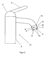
- the Fig. 1 shows - in a schematic representation - a sanitary fitting 1 with an outlet 2, a fitting head 3 with a lever 4 and a fitting foot 5 according to the prior art.
- a means for irradiation 6 in the outlet 2 is integrated, which irradiates a liquid located in the outlet 2 and / or flowing through it with UV light.
- the fitting foot 5 is an electrical supply means 7, for example, a battery integrated.
- the electrical supply means 7 is arranged interchangeably on the edge of the valve foot 5.
- the electrical supply means 7 supplies the irradiation means 6 via an electrical line 8 with a voltage in the low-voltage range, a so-called extra-low voltage.
- the electric circuit is closed via the fitting body.
- the irradiation means 6 has one or more, not individually shown, UV-C emitters for irradiating a liquid flowing out through the outlet 2.
- the irradiation means 6 has a high disinfecting effect with low energy consumption. Due to the low energy consumption, the electrical supply means 7 can supply the irradiation means 6 with a low voltage or a voltage in the low voltage range. Due to the high disinfecting effect of the irradiation medium 6, a disinfection of a comparatively rapidly flowing liquid is made possible. Even with a small residence time of a liquid flowing through the sanitary fitting 1, a leaking liquid is reliably disinfected.
- the one or more UV-C emitters emit light with a wavelength of 100-280 nm.
- Ideal is a wavelength of 254 nm, more precisely 253.7 nm. Existing bacteria, Legionella, viruses, yeasts, fungi or the like are rendered harmless in a very short time. Due to the integration of the electrical supply means 7 in the valve 1 no externally disposed power source is needed. And by the electrical supply of the irradiation means 6 with a low voltage, the sanitary fitting 1 according to the invention can be used without security risk.
- the device 1 according to the invention an advantageous and easy way is created to disinfect a liquid without security risk and with little effort at the point where this occurs from a closed pipe system, for example via a sanitary fitting to an atmosphere. The liquid is therefore disinfected directly at the point of use, at the so-called Point of Use (POU).
- POU Point of Use
- the Fig. 2 shows a device according to the invention in the form of an aerator 11.
- the aerator 11 is fastened by means of a screw 12 to a conventional sanitary fitting 13.
- An aerator also called jet regulator or mixing nozzle, is commonly used in sanitary fittings for air admixture.
- Such an aerator displaces an outflowing jet of liquid with air bubbles.
- the aerator 11 has a fine mesh screen 14 through which a liquid jet flows. This creates an aerated liquid jet that provides high hygienic comfort with low consumption.
- the use of an aerator is common in sanitary fittings.
- the aerator is usually attached by means of a screw on such.
- aerators with an internal thread connection M22 ⁇ 1 or an external thread connection M24 ⁇ 1 are widely used.
- the device according to the invention in the form of an aerator 11 has external dimensions of a standard aerator.
- the irradiation means 6 consists of one or more UV-C emitters 16.
- the UV-C emitters 16, for example UV-C LEDs are arranged in the sieve insert 14 of the aerator 11. These are supplied by the battery 9 as an electrical supply means with a voltage in the low voltage range, a so-called extra voltage.
- the use of UV-C LEDs offers the following advantages. They are robust, have a low heat generation, have a small size and a high irradiation intensity. They are operated in the low voltage range, for example at 5 to 10 or 12 volts and have low energy consumption.
- the power loss of UV-C LEDs is between a few microwatts and a few milliwatts.
- the UV-C LEDs used have a long service life and are wear-free. By positioning them directly at the outlet 2 of the aerator 11, an outflowing liquid is disinfected immediately before it enters the open atmosphere, ie immediately at the point of use, the so-called Point of Use (POU). Due to the low energy consumption of the UV-C LEDs or UV-C emitter 16 only a small footprint in the aerator 11 is required. In addition, the low energy consumption of the UV-C LEDs leads to a long service life of the battery 9.
- the battery 9 is arranged exchangeably or can be exchanged together with the device 11.
- the Fig. 3 shows the aerator 11 from Fig. 2 in a side view.
- the aerator 11 has a connection thread 12 for connection to a sanitary fitting 13, an outlet 2 and a sieve 14.
- UV C emitters 16, designed as UV-C LEDs, are arranged in the sieve 14.
- An electrical supply means, a battery 9, for supplying the UV-C radiator 16 is arranged by means of a holder 18, which is held by Verstrebimplantation 19 in the aerator 11.
- the electrical supply means is arranged in the center of the aerator 11.
- another position of the electrical supply means such as on a wall of the aerator 11, is provided.
- such an electrical supply means may also be disposed within and supported by the screen 14.
- a switch 15 is arranged within the circuit 8, which connects the UV-C emitter 16 to the battery 9, through which the circuit is closed to the UV-C emitters 16. It is the switch 15 is an electrical contact, which is closed by flowing liquid.
- the further circuit is guided via a line integrated into a wall 20 of the aerator 11.
- the outlet 2 has inside wall surfaces, which are designed to be reflective. A reflection of the UV-C emitter inside the spout 2 is achieved for example by polished stainless steel or chrome surfaces. In addition, the spout 2 is executed dead space free.
- a proximity switch can also be arranged in the aerator, which closes an electrical supply circuit for the UV-C LEDs as soon as a user comes near the device.
- Fig. 4 now shows the aerator 11 according to the invention in its plan view.
- the fine-meshed sieve 14 of the aerator 11 can be seen.
- the UV-C LEDs or UV-C lamps 16 there are several possibilities of arrangement within the screen 14 and / or within the aerator 11.
- An example is an aerator 11 with four UV-C LEDs arranged symmetrically about a center of the aerator 11 or UV-C emitters 16.
- a battery 9 designed as a coin cell is held in a holder 18.
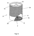
- the Fig. 5 shows another aerator 21 in three-dimensional view. This again has means for connection to a sanitary fitting. In the figure, these are shown as connecting thread 12. But it can also be other means of connection such as a universal coupling element.
- UV lamps or UV-C lamps 16 are arranged in the screen 14 of the aerator 21 in turn UV lamps or UV-C lamps 16 are arranged.
- a solar energy converting means for electrical power generation is used in this aerator 21, a solar energy converting means.
- the wall of the aerator 21 is equipped with solar cells 24. These convert light energy into electrical energy, which serves to supply the UV lamps 16.
- the aerator 21 on a held by means of braces 19 and brackets 18 accumulator 23. This is charged by the solar cells and serves for temporary energy storage.
- Such a photovoltaic or solar module integrated in the aerator 21 creates a long-lasting self-sufficient device according to the invention.
- the device 21 according to the invention is independent of local power supply conditions.
- a device is provided which is of particular advantage for travelers. Travelers can carry such an aerator 21, ideally designed with a universal coupling element, to achieve safe water quality in adverse hygienic conditions on site.
- Such a universally usable aerator can be easily attached to a sanitary fitting on site.
- a proximity switch 25 is arranged in the aerator 21. This closes an electrical supply circuit for the UV-C emitters 16 as soon as someone comes in the vicinity of the aerator 21.
- the proximity switch 25 may additionally be used to cause the liquid to flow.
- the valve that opens or closes the line is also used opened or closed by the proximity switch signal.
- electrical connection lines and / or contact connections are provided by the aerator 21 to a valve.
- the Fig. 6 shows a further, non-inventive device in the form of a pipe 31.
- a turbine unit 32 with blades 33 is installed in the pipe 31.
- the turbine blades 33 are driven by the liquid flowing through the device.
- a generator 34 is driven, which converts the resulting rotational energy into electrical energy.
- a bracket 35 with braces 36 is arranged in the pipe 31.
- the star-shaped bracing is used to attach the UV lamps 16.
- Such a pipeline disinfecting device according to the invention can be used, for example, as a connecting line to a toilet cistern.
- the Fig. 7 shows a further device not according to the invention, which is used for example in bath outlets.
- a flat designed outlet 42 is arranged on a fitting body 41.
- the electrical supply means is formed by a solar module, consisting of solar cells 24 and a - not shown here - energy storage, wherein the solar module is arranged on the fitting body 41 or is integrated in this.
- the fitting body is connected to a pipe 43 which is continued in the fitting body 41 and opens at an opening 44 in the flat-shaped outlet (42). Outflowing water is disinfected by arranged at the outlet 42 UV lamp 16.
- a switch 15 is provided which closes the circuit for the UV lamps 16 as soon as liquid flowing through closes its electrical contacts.
- the spout 42 shown consists at least in part of UV-translucent material, such as quartz glass.
- the UV-C emitters 16 radiate into the UV-transparent material, whereby the entire translucent area is permeated with UV-C radiation.
- the effluent liquid flows over the flat-shaped outlet 42, which is permeated with UV-C radiation, and is disinfected in this way.
- a residence time of a liquid to be disinfected, during which the liquid is exposed to UV irradiation can be increased.
- a lower irradiance is sufficient in such an arrangement.
- the invention is for example in sanitary fittings, such as vanities, bidets. Rinses, bath spouts, shower heads or injection nozzles can be used in the swimming pool area.
Description
Die Erfindung betrifft eine Vorrichtung mit einem Auslauf für eine Flüssigkeit, insbesondere Wasser, wobei die Flüssigkeit am Auslauf aus einem geschlossenen Leitungssystem an eine offene Atmosphäre tritt und mit einem Mittel zur Bestrahlung der Flüssigkeit mit UV-Licht, wobei das Mittel zur Bestrahlung elektrisch versorgbar und am Auslauf angeordnet oder in diesen integriert ist.The invention relates to a device with a spout for a liquid, in particular water, wherein the liquid at the outlet from a closed conduit system to an open atmosphere and with a means for irradiation of the liquid with UV light, wherein the means for irradiation electrically supplied and arranged at the outlet or is integrated in this.
Eine derartige Vorrichtung ist aus der
Aus der
Die
Durch die
Aus der
Durch die
Eine Desinfektionseinrichtung ist durch die
Der Erfindung liegt das Problem zu Grunde, eine wenig aufwändige Vorrichtung der eingangs genannten Art zu schaffen, die eine zuverlässige Desinfektion gewährleistet.The invention is based on the problem to provide a little expensive device of the type mentioned, which ensures reliable disinfection.
Die Lösung des Problems sieht vor, dass die Vorrichtung als Luftsprudler ausgebildet ist, wobei das Mittel zur Bestrahlung für eine Desinfektionswirkung bei niedrigem Energieverbrauch ein oder mehrere UV-C-LEDs aufweist, welche die ausströmende Flüssigkeit unmittelbar vor deren Übertritt in die offene Atmosphäre, an deren Ort des Gebrauchs, desinfizieren und ein elektrisches Versorgungsmittel das Bestrahlungsmittel mit einer Kleinspannung versorgt, die bis zu 25V Wechselspannung oder 60V Gleichspannung beträgt, und das Bestrahlungsmittel in einem Siebeinsatz des Luftsprudlers angeordnet ist.The solution of the problem provides that the device is designed as an aerator, wherein the means for irradiation for a disinfecting effect with low energy consumption comprises one or more UV-C LEDs, which the effluent immediately before their passage into the open atmosphere, at their place of use, disinfect and an electrical supply means supplies the irradiation medium with a low voltage, which is up to 25V AC or 60V DC, and the irradiation means is arranged in a sieve insert of the aerator.
Infolge der hohen Desinfektionswirkung des Mittels zur Bestrahlung ist erstmals eine Desinfektion einer aus einem Auslauf ausfließenden und/oder ausströmenden Flüssigkeit ermöglicht. Die Vorteile eines erfindungsgemäßen Bestrahlungsmittels als Desinfektionsmittel liegen in seiner sich in Bruchteilen einer Sekunde entfaltenden desinfizierenden, Bakterien abtötenden oder keimtötenden Wirkung. Bakterien, Legionellen, Viren, Hefen und Pilze werden durch die erfindungsgemäße Desinfektionsvorrichtung unschädlich gemacht. Auch bei einer schnell ausströmenden Flüssigkeit und einer damit verbundenen vergleichsweise geringen Verweilzeit einer Flüssigkeit beim Durchströmen einer herkömmlichen, insbesondere für eine Trink-, Brauch- und/oder Grauwasserentnahme vorgesehenen Armatur, Entnahmestelle und/oder Düse ist durch die Erfindung eine zuverlässige Desinfektion der auslaufenden und/oder ausströmenden Flüssigkeit geschaffen. Da die Druckwerte eines Wasserleitungssystems Grenzwerten unterliegen, kann die maximale Strömungsgeschwindigkeit einfach ermittelt und dazu die entsprechende Leistung des Bestrahlungs- oder Desinfektionsmittels festgelegt werden.As a result of the high disinfecting effect of the agent for irradiation, it is possible for the first time to disinfect a fluid flowing out of an outlet and / or outflowing. The advantages of an irradiation agent according to the invention as a disinfectant lie in its disinfectant, bactericidal or germicidal effect unfolding in fractions of a second. Bacteria, Legionella, viruses, yeasts and fungi are rendered harmless by the disinfecting device according to the invention. Even with a fast-flowing liquid and an associated comparatively low residence time of a liquid flowing through a conventional, especially for a drinking, service and / or greywater extraction provided fitting, sampling point and / or nozzle is a reliable disinfection of the expiring and / or effluent created. Since the pressure values of a water supply system are subject to limit values, the maximum flow rate can be easily determined and the corresponding power of the irradiation or disinfectant can be determined for this purpose.
Die Desinfektionswirkung ist an die zu desinfizierende Flüssigkeit, insbesondere an deren Trübungsgrad, Temperatur, Bakterien- und/oder Absorptionsrate angepasst. Als Maß für die Desinfektionswirkung wird die Bestrahlungsdosis oder fluenz als dem Produkt aus Bestrahlungsstärke und Einwirkdauer herangezogen. Bei der Trinkwasserbehandlung innerhalb von Gebäuden wird üblicherweise die sogenannte Reduktionsäquivalentfluenz, bezogen auf eine Bestrahlungswellenlänge von 254 nm, angegeben. Für die Trinkwasserbehandlung ist es von Vorteil, dass die Bestrahlungsdosis oder die Reduktionsäquivalentfluenz der erfindungsgemäßen Vorrichtung bei einer Bestrahlungswellenlänge von 254 nm mindestens 400 J/m2 oder 40 mJ/cm2 betragen kann. Für einige Anwendungen, wie beispielsweise der Nachbehandlung von Trinkwasser an einem Sanitärarmaturenauslauf, haben sich geringere Bestrahlungsdosen als ausreichend erwiesen. Dabei ist es zweckmäßig, wenn die Vorrichtung in etwa eine Bestrahlungsdosis oder eine Reduktionsäquivalentfluenz von mindestens 150 J/m2 oder 15 mJ/cm2 erbringt.The disinfecting effect is adapted to the liquid to be disinfected, in particular to its degree of turbidity, temperature, bacterial and / or absorption rate. As a measure of the disinfecting effect is the irradiation dose or fluence than the product taken from irradiance and exposure time. In the case of drinking water treatment within buildings, the so-called reduction equivalent fluence, based on an irradiation wavelength of 254 nm, is usually stated. For drinking water treatment, it is advantageous that the irradiation dose or the reduction equivalent fluence of the device according to the invention can be at least 400 J / m 2 or 40 mJ / cm 2 at an irradiation wavelength of 254 nm. For some applications, such as after-treatment of drinking water at a sanitary tap outlet, lower doses of radiation have been found to be sufficient. It is expedient for the device to yield approximately an irradiation dose or a reduction equivalent fluence of at least 150 J / m 2 or 15 mJ / cm 2 .
Durch den niedrigen Energieverbrauch des Bestrahlungs- oder Desinfektionsmittels und durch dessen elektrische Versorgung mit Kleinspannung ist die Erfindung auch bei Sanitärarmaturen, wie Trinkwasserarmaturen, ohne Sicherheitsrisiko verwendbar. Unter einer Kleinspannung versteht man eine elektrische Spannung im Niedervoltbereich. Dabei wird eine Versorgung bis zu 25V Wechselspannung und bis zu 60V Gleichspannung als Kleinspannung oder Schutzkleinspannung bezeichnet. Idealerweise versorgt ein elektrisches Versorgungsmittel gemäß der Erfindung das Bestrahlungsmittel mit einer Spannung, insbesondere einer Gleichspannung, im Niedervoltbereich von bis zu 15 Volt.Due to the low energy consumption of the irradiation or disinfectant and its electrical supply with low voltage, the invention is also used in sanitary fittings, such as drinking water fittings, without security risk. Under a low voltage is meant an electrical voltage in the low voltage range. In this case, a supply up to 25V AC and up to 60V DC is referred to as low voltage or safety extra-low voltage. Ideally, an electrical supply means according to the invention supplies the irradiation means with a voltage, in particular a DC voltage, in the low-voltage range of up to 15 volts.
Durch die Erfindung ist eine besonders vorteilhafte und einfache Möglichkeit geschaffen, eine Flüssigkeit ohne Sicherheitsrisiko und mit geringem Aufwand an oder in der Nähe der Stelle zu desinfizieren, wo diese aus einem geschlossenen Leitungssystem an eine Atmosphäre tritt. Die Flüssigkeit wird unmittelbar an deren Ort des Gebrauchs, am sogenannten Point of Use (POU), desinfiziert.The invention provides a particularly advantageous and easy way to disinfect a liquid without security risk and with little effort at or near the point where it enters from a closed conduit system to an atmosphere. The liquid is disinfected directly at its place of use, at the so-called Point of Use (POU).
Bei einer Integration des elektrischen Versorgungsmittels in den Auslauf und/oder die Vorrichtung, ist eine extern angeordnete Energieversorgungs- oder Stromquelle entbehrlich. Das elektrische Versorgungsmittel ist dabei zweckmäßig in den Auslauf und/oder die Vorrichtung geschützt integriert oder eingebettet. Die Zuleitungen sind nicht mehr freiliegend in unmittelbarer Nähe eines Auslaufes angebracht, sondern ebenfalls in den Auslauf und/oder die Vorrichtung integriert. Sie stellen damit kein Risiko für äußere Angriffe oder schädigende Berührungen dar. Somit ist eine autarke Einheit geschaffen, bei der alle für eine Desinfektion von Flüssigkeiten notwendigen Komponenten in den Auslauf und/oder in die Vorrichtung eingebaut sind. Dem Anwender bietet sich nach außen hin kein Unterschied zu einer herkömmlichen Armatur. Dies ist besonders bei häuslichen Sanitärarmaturen, wie einer Trink-, Brauch- und/oder Grauwasserarmatur, von Vorteil.In an integration of the electrical supply means in the outlet and / or the device, an externally disposed power supply or power source is unnecessary. The electrical supply means is expediently integrated or embedded protected in the outlet and / or the device. The supply lines are no longer exposed in the immediate vicinity of an outlet, but also integrated into the outlet and / or the device. They therefore pose no risk for external attacks or harmful contacts. Thus, a self-sufficient unit is created in which all components necessary for the disinfection of liquids are installed in the outlet and / or in the device. The user has no difference to a conventional valve. This is particularly advantageous in domestic sanitary fittings, such as a drinking, service and / or greywater tap.
Erfindungsgemäß weist das Mittel zur Bestrahlung ein oder mehrere UV-C-Strahler auf. Die Vorteile eines solchen Bestrahlungs- und/oder Desinfektionsmittels sind dessen hohe desinfektionswirksame Strahlungsintensität im Vergleich zu zu Illuminationszwecken verwendeten UV-A und/oder UV-B-Strahlern. Die UV-C-Strahler senden dabei Licht mit einer Wellenlänge von 100 bis 280 nm aus. Als besonders effektiv hat es sich erwiesen, die Desinfektion bei einer Wellenlänge von 254 nm, genauer 253,7 nm, durchzuführen. Bakterien, Legionellen, Viren, Hefen und Pilze werden so zuverlässig unschädlich gemacht.According to the invention, the means for irradiation on one or more UV-C emitters. The advantages of such an irradiation and / or disinfectant are its high disinfectant radiation intensity compared to UV-A and / or UV-B emitters used for illumination purposes. The UV-C emitters emit light with a wavelength of 100 to 280 nm. It has proven to be particularly effective to carry out the disinfection at a wavelength of 254 nm, more precisely 253.7 nm. Bacteria, Legionella, viruses, yeasts and fungi are reliably rendered harmless.
Erfindungsgemäß weist das Mittel zur Bestrahlung ein oder mehrere UV-C-LEDs aufweist. LEDs, also lichtemittierende Dioden oder Leuchtdioden, sind robust, haben eine geringe Wärmeentwicklung und weisen eine geringe Baugröße bei gleichzeitig hoher Bestrahlungsintensität auf. Ihre Bestrahlungsintensität bleibt über ihren Lebenszeitraum gleich. Sie werden im Kleinspannungsbereich beispielsweise bei 5 bis 12 Volt betrieben und haben einen geringen Energieverbrauch. Die Verlustleistung von UV-C-LEDs ist sehr gering und beträgt je nach Typ zwischen wenigen Mikrowatt und einigen Milliwatt. Darüber hinaus haben LEDs eine Lebensdauer von mehreren tausend Stunden und sind wartungsfrei.According to the invention, the means for irradiation comprises one or more UV-C LEDs. LEDs, ie light-emitting diodes or light-emitting diodes, are robust, have a low heat development and have a small overall size with high irradiation intensity. Their radiation intensity remains the same over their lifetime. They are operated in the low voltage range, for example at 5 to 12 volts and have low energy consumption. The power loss of UV-C LEDs is very low and is between a few microwatts and a few milliwatts depending on the type. In addition, LEDs have a lifespan of several thousand hours and are maintenance-free.
Als besonders zweckmäßig hat es sich erwiesen, wenn das Mittel zur elektrischen Versorgung eine Batterie ist. Durch den geringen Energieverbrauch des Desinfektionsmittels ist nur ein geringer Platzbedarf in einem Auslauf einer erfindungsgemäßen Vorrichtung erforderlich. Der geringe Energieverbrauch des Desinfektionsmittels führt zu einer langen Lebensdauer der Batterie. Daher ist nur ein geringer Wartungsaufwand einer erfindungsgemäßen Vorrichtung erforderlich. Die Batterie ist austauschbar angeordnet oder kann zusammen mit der Vorrichtung ausgetauscht werden.It has proven particularly expedient if the means for supplying electrical power is a battery. Due to the low energy consumption of the disinfectant only a small space requirement in a spout of a device according to the invention is required. The low energy consumption of the disinfectant leads to a long battery life. Therefore, only a small amount of maintenance of a device according to the invention is required. The battery is interchangeable or can be replaced with the device.
Alternativ ist das Mittel zur elektrischen Versorgung durch eine Turbine und/oder eine Turbineneinheit gebildet, die von einer durch die Vorrichtung strömenden Flüssigkeit angetrieben wird. Dabei ist die Turbine und/oder Turbineneinheit innerhalb der Vorrichtung angeordnet, so dass deren Schaufeln von der durch die Vorrichtung strömenden Flüssigkeit angetrieben werden. Ein innerhalb der Turbine und/oder Turbineneinheit angeordneter Generator wandelt die Rotationsenergie in elektrische Energie um.Alternatively, the means for electrical supply by a turbine and / or a turbine unit is formed, which is driven by a liquid flowing through the device. In this case, the turbine and / or turbine unit is arranged within the device, so that their blades are driven by the liquid flowing through the device. A generator disposed within the turbine and / or turbine unit converts the rotational energy into electrical energy.
Alternativ ist das Mittel zur elektrischen Versorgung durch ein Solarenergie umwandelndes Mittel gebildet, das am Auslauf und/oder an der Vorrichtung angeordnet ist. Durch ein solches Photovoltaik- oder Solarmodul ist eine langlebige autarke Vorrichtung geschaffen.Alternatively, the means for electrical supply is formed by a solar energy converting means disposed on the outlet and / or on the device. By such a photovoltaic or solar module, a long-lasting self-sufficient device is created.
Selbstverständlich liegt auch eine Kombination einer Turbine und/oder einem Solarmodul mit einer wiederaufladbaren Batterie, einem Akkumulator, im Rahmen der Erfindung.Of course, a combination of a turbine and / or a solar module with a rechargeable battery, an accumulator, within the scope of the invention.
Die Wirksamkeit der Flüssigkeits-, insbesondere der Wasserbestrahlung, wird dadurch verbessert, dass der Auslauf im Innern reflektierend und/oder totraumfrei gestaltet ist. Eine gute Reflexion der UV-C-Strahlen im Innern des Auslaufs wird beispielsweise durch polierte Edelstahl- oder Chromoberflächen erreicht. Die Totraumfreiheit und die Reflexion von Umgebungsflächen verringert die erforderliche Lichtintensität bzw. die Verweildauer des Wassers im Beleuchtungs- oder Bestrahlungsbereich.The effectiveness of the liquid, in particular the water irradiation, is improved by the fact that the outlet is designed to be reflective and / or dead space inside. Good reflection of the UV-C rays inside the spout is achieved, for example, by polished stainless steel or chrome surfaces. The dead space and the reflection of surrounding areas reduces the required light intensity or the residence time of the water in the lighting or irradiation area.
Idealerweise tritt das Wasser nahe dem Mittel zur Bestrahlung aus. Das Bestrahlungsmittel bestrahlt die Austrittsflächen des Auslaufes, bevor das Wasser austritt. Bakterien, die sich während einer Wasserentnahmepause an den Austrittsflächen angesiedelt haben, werden unschädlich gemacht.Ideally, the water exits near the means of irradiation. The irradiation medium irradiates the exit surfaces of the spout before the water exits. Bacteria that have settled on the exit surfaces during a water withdrawal break are rendered harmless.
Zum Einschalten des Bestrahlungsmittels kann in der Vorrichtung ein Näherungsschalter angeordnet sein, der einen elektrischen Versorgungskreis für das Bestrahlungsmittel schließt, sobald jemand in die Nähe der Vorrichtung kommt. Ein solcher Näherungsschalter kann zusätzlich ein Strömen der Flüssigkeit bewirken. Beispielsweise kann bei einer Trinkwasserarmatur das Ventil, das die Leitung öffnet und/oder schließt, ebenfalls durch den Näherungsschalter geöffnet und/oder geschlossen werden. Aufgrund der Tatsache, dass elektrischer Strom schneller fließt als Wasser, leuchten die LEDs früher als das Wasser am Auslauf eintritt. Dadurch kann kein Wasser ausfließen, ohne desinfiziert zu werden. Auch die Wände und eventuelle Restbestände von Wasser innerhalb der Vorrichtung werden sicher desinfiziert. Alternativ ist es vorgesehen, den Stromkreis für das Desinfektionsmittel mittels eines Kontaktes durch die Flüssigkeit selbst zu schließen.For switching on the irradiation means, a proximity switch can be arranged in the device, which closes an electrical supply circuit for the irradiation means, as soon as someone comes in the vicinity of the device. Such a proximity switch can additionally cause a flow of the liquid. For example, in a drinking water fitting, the valve that opens and / or closes the pipe can also be opened and / or closed by the proximity switch. Due to the fact that electric current flows faster than water, the LEDs light up earlier as the water enters the spout. As a result, no water can flow out without being disinfected. Also, the walls and any remnants of water within the device are safely disinfected. Alternatively, it is provided to close the circuit for the disinfectant by means of a contact through the liquid itself.
Zusätzlich sind Mittel zur Steuerung beispielsweise einer Zwischendurchbestrahlung und/oder -spülung bei längeren Wasserentnahmepausen vorgesehen. Wenn eine Vorrichtung über einen längeren Zeitraum nicht genutzt wird, können ein oder mehrere UV-Strahler eingeschaltet werden. Dies erfolgt beispielsweise zeitgesteuert, alternativ wird ein kurzzeitiges Öffnen der Vorrichtung veranlasst, um eine Zwischendurchspülung durchzuführen.In addition, means are provided for controlling, for example, an intermediate irradiation and / or rinsing during longer water withdrawal pauses. If a device is not used for a long period of time, one or more UV lamps can be switched on. This is done, for example, time-controlled, alternatively, a brief opening of the device is caused to perform an intermediate purging.
Weiterhin ist vorgesehen, Temperatur-, Mengen- und/oder Druckfühler in die Vorrichtung zu integrieren.Furthermore, it is provided to integrate temperature, quantity and / or pressure sensor in the device.
Idealerweise besitzt die Vorrichtung zusätzliche Mittel zur Strömungsbeeinflussung, insbesondere Luftbeimischung. Diese können beispielsweise Elemente eines Strahlreglers, einer Mischdüse und/oder eines Luftsprudlers sein, der einen Flüssigkeitsstrahl mit Luftperlen versetzt. Dadurch entsteht bei geringerem Verbrauch ein Flüssigkeitsstrahl mit hohem Hygienekomfort. Letzterer wird bei Verwendung von UV-C-Strahlern noch dadurch unterstützt, dass deren Strahlung und/oder ein Teil davon fluoreszierende Wirkung auf den aus dem Auslauf austretenden oder über einen Auslauf fließenden Flüssigkeitsstrahl besitzt. Da UV-C-Licht nicht farblos ist, erscheint beispielsweise Wasser in einer hellen, blauen Farbe, was optisch sichtbar dessen Desinfektion anzeigt. Und das Hygieneempfinden wird dadurch unterstützt.Ideally, the device has additional means for influencing the flow, in particular air admixing. These may be, for example, elements of a jet regulator, a mixing nozzle and / or an aerator which displaces a liquid jet with air bubbles. This results in lower consumption, a liquid jet with high hygiene comfort. The latter is supported by the use of UV-C emitters even more so that their radiation and / or a part thereof has a fluorescent effect on the emerging from the outlet or flowing through a spout liquid jet. Since UV-C light is not colorless, for example, water appears in a bright, blue color, which visually indicates its disinfection. And the sense of hygiene is thereby supported.
Nach der Erfindung kann die Vorrichtung Mittel zur Verbindung mit und/oder Anordnung an einer Armatur, insbesondere einer Trink-, Brauch- und/oder Grauwasserarmatur, aufweisen. Dies können beispielsweise Schraubverbindungen, Klemmverbindungen, Bajonettverbindungen, universelle Kupplungselemente oder dergleichen sein. Dadurch sind auch bestehende Armaturen mit einer erfindungsgemäßen Vorrichtung ständig oder temporär nach- oder umrüstbar. Dies ist von besonderem Vorteil für Reisende, die bei nachteiligen hygienischen Bedingungen auf eine sichere Wasserqualität Wert legen.According to the invention, the device may comprise means for connection to and / or arrangement on a fitting, in particular a drinking, service and / or gray water fitting. These can be, for example, screw connections, clamp connections, bayonet connections, universal coupling elements or the like. As a result, existing fittings with a device according to the invention are constantly or temporarily nach- or convertible. This is of particular advantage for travelers who attach importance to a safe water quality in adverse hygienic conditions.
Idealerweise besitzt die Vorrichtung die äußeren Abmessungen eines StandardStrahlreglers oder eines Standard-Luftsprudlers. Durch eine Anpassung der äußeren Abmessungen des Luftsprudlers an gängige Standardgrößen ist eine Vorrichtung geschaffen, die zu einem Luftsprudler als einem Standardbauteil, das bei einer überwiegenden Zahl von Herstellern Verwendung findet, kompatibel ist. Verbreitet sind beispielsweise Strahlregler oder Luftsprudler mit einem Innengewindeanschluss M22 x 1 oder einem Außengewindeanschluss M24 x 1. Die Strahlerleistung ist auf die definierten Raum- und Auslaufverhältnisse eines solchen Standardstrahlreglers oder - luftsprudlers abgestimmt. Damit ist die erfindungsgemäße Vorrichtung in einfacher Art und Weise bei bestehenden Armaturen, beispielsweise anstelle eines Standardluftsprudlers, nachrüstbar.Ideally, the device has the external dimensions of a standard jet aerator or a standard aerator. By adapting the external dimensions of the aerator to current standard sizes, a device is provided which is compatible with an aerator as a standard component used by a majority of manufacturers. For example, jet regulators or aerators with an M22 x 1 female thread connection or an M24 x 1 male thread connection are widely used. The emitter power is matched to the defined space and outflow conditions of such a standard jet regulator or aerator. Thus, the device according to the invention in a simple manner in existing fittings, for example, instead of a standard air bubbler, retrofitted.
Wie schon zuvor erwähnt kann die Vorrichtung eine Wasserentnahmestelle einer Trinkwasserleitung bilden, wodurch eine Vielzahl an Anwendungsgebieten erschlossen ist.As already mentioned, the device can form a water intake point of a drinking water line, whereby a large number of application areas is developed.
Die Erfindung ist bei Sanitärarmaturen wie bei Waschtischen, Bidets, Spülen oder bei Wannenausläufen nutzbar.The invention can be used in sanitary fittings such as washbasins, bidets, sinks or bath spouts.
Die Erfindung bleibt nicht auf Standardbauteile beschränkt, sondern wird auch bei den unterschiedlichsten, individuellen Sanitärarmaturenausführungen, wie sie beispielsweise bei Duschköpfen, Wannenausläufen oder bei Einspritzdüsen im Pool- oder Wannenbereich vorkommen, benutzt. Im Rahmen der Erfindung sollen auch Düsen oder dergleichen als Auslauf verstanden werden. Die Verwendung der Erfindung ist somit ebenfalls bei geschlossenen Brauchwassersystemen, in denen die Bildung von Bakterien oder dergleichen üblicherweise sehr hoch ist, vorgesehen und von großem Vorteil.The invention is not limited to standard components, but is also in the most varied, individual sanitary fitting designs, as for example used in shower heads, bath outlets or injectors in the pool or tub area, used. In the context of the invention, nozzles or the like are to be understood as an outlet. The use of the invention is therefore likewise provided and of great advantage in closed service water systems in which the formation of bacteria or the like is usually very high.
Ausführungsbeispiele der Erfindung sind in den Zeichnungen dargestellt und werden im Folgenden näher beschrieben. Der besseren Übersichtlichkeit halber sind schematische Darstellungen gezeigt. Es zeigen die
- Fig. 1
- eine Sanitärarmatur gemäß dem Stand der Technik; die
- Fig. 2
- eine zweite erfindungsgemäße Vorrichtung in Form eines Luftsprudlers; die
- Fig. 3, 4
- Detailansichten (Seitenansicht, Draufsicht) des erfindungsgemäßen Luftsprudlers; die
- Fig. 5
- einen weiteren erfindungsgemäßen Luftsprudler in dreidimensionaler Ansicht; die
- Fig. 6
- eine weitere erfindungsgemäße Vorrichtung in Form einer Rohrleitung und die
- Fig. 7
- eine weitere erfindungsgemäße Vorrichtung mit einem flächig gestalteten Auslauf.
- Fig. 1
- a sanitary fitting according to the prior art; the
- Fig. 2
- a second device according to the invention in the form of an aerator; the
- Fig. 3, 4
- Detailed views (side view, top view) of the aerator according to the invention; the
- Fig. 5
- a further aerator according to the invention in three-dimensional view; the
- Fig. 6
- another device according to the invention in the form of a pipeline and the
- Fig. 7
- a further device according to the invention with a flat design spout.
Die
Die
Im Luftsprudler 11 befinden sich - in der Figur schematisch dargestellt - als elektrisches Versorgungsmittel eine Batterie 9, Bestrahlungsmittel 6 und ein Kontakt oder Schalter 15. Wiederum besteht das Bestrahlungsmittel 6 aus ein oder mehreren UV-C-Strahlern 16. Die UV-C-Strahler 16, beispielsweise UV-C-LEDs, sind im Siebeinsatz 14 des Luftsprudlers 11 angeordnet. Diese werden durch die Batterie 9 als elektrisches Versorgungsmittel mit einer Spannung im Niedervoltbereich, einer sogenannten Kleinspannung, versorgt. Durch die Verwendung von UV-C-LEDs ergeben sich folgende Vorteile. Sie sind robust, haben eine geringe Wärmeentwicklung, weisen eine geringe Baugröße und eine hohe Bestrahlungsintensität auf. Sie werden im Kleinspannungsbereich, beispielsweise bei 5 bis 10 oder 12 Volt betrieben und haben einen geringen Energieverbrauch. Die Verlustleistung von UV-C-LEDs beträgt dabei zwischen wenigen Mikrowatt und einigen Milliwatt. Darüber hinaus haben die verwendeten UV-C-LEDs eine lange Lebensdauer und sind verschleißfrei. Durch deren Positionierung unmittelbar am Auslauf 2 des Luftsprudlers 11 wird eine ausströmende Flüssigkeit unmittelbar vor deren Übertritt in die offene Atmosphäre, also unmittelbar am Ort ihres Gebrauchs, des sogenannten Point of Use (POU), desinfiziert. Durch den geringen Energieverbrauch der UV-C-LEDs oder UV-C-Strahler 16 ist nur ein geringer Platzbedarf im Luftsprudler 11 erforderlich. Zudem führt der geringe Energieverbrauch der UV-C-LEDs zu einer langen Lebensdauer der Batterie 9. Die Batterie 9 ist austauschbar angeordnet oder kann zusammen mit der Vorrichtung 11 ausgetauscht werden.In the
Die
Sobald ausfließende Flüssigkeit den Kontakt oder den Schalter 15 schließt, leuchten die UV-C-Strahler 16 und austretendes Wasser wird desinfiziert. Alternativ zu einem solchen Kontaktschalter 15 kann im Luftsprudler auch ein Näherungsschalter angeordnet sein, der einen elektrischen Versorgungskreis für die UV-C-LEDs schließt, sobald ein Benutzer in die Nähe der Vorrichtung kommt.As soon as effluent liquid closes the contact or switch 15, the UV-
Die
Zum Einschalten der UV-C-Strahler 16 ist im Luftsprudler 21 ein Näherungsschalter 25 angeordnet. Dieser schließt einen elektrischen Versorgungskreis für die UV-C-Strahler 16, sobald jemand in die Nähe des Luftsprudlers 21 kommt. Der Näherungsschalter 25 kann zusätzlich dafür verwendet werden, ein Strömen der Flüssigkeit zu bewirken. Dazu wird bei einer Armatur das Ventil, das die Leitung öffnet oder schließt, ebenfalls durch das Näherungsschaltersignal geöffnet oder geschlossen. Dazu sind beispielsweise - hier nicht dargestellte - elektrische Verbindungsleitungen und/oder Kontaktverbindungen vom Luftsprudler 21 zu einer Armatur vorgesehen. Alternativ ist vorgesehen, einen ohnehin in einer Armatur vorhandenen, zum Öffnen oder Schließen der Armatur benutzten Näherungsschalter zum Schließen oder Öffnen des Stromkreises für das UV-Bestrahlungsmittel zu verwenden. Durch die Anordnung der UV-C-Strahler 16 unmittelbar am Auslauf 2 des Luftsprudlers 21 wird zusätzlich ein optisch sichtbarer Effekt erzielt. Das Wasser erscheint in einer hellen, blauen Farbe, was dessen Desinfektion anzeigt und das Hygieneempfinden verstärkt.To turn on the UV-
Die
Die
Die Erfindung ist beispielsweise bei Sanitärarmaturen, wie Waschtischen, Bidets. Spülen, Wannenausläufen, Duschköpfen oder Einspritzdüsen im Schwimmbadbereich nutzbar.The invention is for example in sanitary fittings, such as vanities, bidets. Rinses, bath spouts, shower heads or injection nozzles can be used in the swimming pool area.
Claims (9)
- Device having an outlet (2, 42) for a liquid, in particular water, wherein the liquid at the outlet (2, 42) enters an open atmosphere from a closed conduction system, and having a means for irradiating (6) the liquid with UV light, it being possible for the irradiation means (6) to be supplied with electrical power and the irradiation means (6) being arranged at the outlet (2, 42) or integrated in said outlet,
characterized in that
the device is designed as an aerator (11), wherein the irradiation means (6) has one or more UV-C LEDs for a disinfection action together with a low level of energy consumption, which disinfect the outflowing liquid immediately before it is passed to the open atmosphere, at the location at which it is used, and an electrical supply means (7) supplies the irradiation means (6) with a low voltage which is up to 25V AC or 60V DC, and the irradiation means is arranged in a screen insert (14) of the aerator (11). - Device according to Claim 1, characterized in that the electrical supply means (7) is integrated in the outlet (2, 42) and/or the device.
- Device according to either of Claims 1 and 2, characterized in that the electrical supply means (7) is a battery (9).
- Device according to one of Claims 1 to 3, characterized in that the electrical supply means (7) is formed by a turbine and/or a turbine unit (32) which is driven by a liquid which flows through the device.
- Device according to one of Claims 1 to 4, characterized in that the electrical supply means (7) is formed by a means which converts solar energy and is arranged at the outlet (2, 42) and/or on the device.
- Device according to one of Claims 1 to 5, characterized in that the outlet (2, 42) is designed to be reflective in the interior.
- Device according to one of Claims 1 to 6, characterized in that control means and/or temperature, quantity and/or pressure sensors are integrated.
- Device according to one of Claims 1 to 7, characterized in that the device has additional means (14) for admixing air.
- Device according to one of Claims 1 to 8, characterized in that the device has means (12) for connection to and/or arrangement on a fitting.
Applications Claiming Priority (2)
| Application Number | Priority Date | Filing Date | Title |
|---|---|---|---|
| DE200810047069 DE102008047069A1 (en) | 2008-09-12 | 2008-09-12 | Device with a spout for a liquid |
| PCT/EP2009/006412 WO2010028779A1 (en) | 2008-09-12 | 2009-09-04 | Disinfecting device having power supply means and fluid outlet |
Publications (2)
| Publication Number | Publication Date |
|---|---|
| EP2323952A1 EP2323952A1 (en) | 2011-05-25 |
| EP2323952B1 true EP2323952B1 (en) | 2015-11-11 |
Family
ID=41171082
Family Applications (1)
| Application Number | Title | Priority Date | Filing Date |
|---|---|---|---|
| EP09778327.8A Active EP2323952B1 (en) | 2008-09-12 | 2009-09-04 | Disinfecting device having power supply means and fluid outlet |
Country Status (14)
| Country | Link |
|---|---|
| US (1) | US8421032B2 (en) |
| EP (1) | EP2323952B1 (en) |
| JP (1) | JP2012501835A (en) |
| CN (1) | CN102164862A (en) |
| AU (1) | AU2009291254B2 (en) |
| BR (1) | BRPI0913466B1 (en) |
| CA (1) | CA2735851A1 (en) |
| DE (1) | DE102008047069A1 (en) |
| DK (1) | DK2323952T3 (en) |
| ES (1) | ES2561403T3 (en) |
| HU (1) | HUE026857T2 (en) |
| MX (1) | MX2011002611A (en) |
| WO (1) | WO2010028779A1 (en) |
| ZA (1) | ZA201101387B (en) |
Cited By (1)
| Publication number | Priority date | Publication date | Assignee | Title |
|---|---|---|---|---|
| US10180248B2 (en) | 2015-09-02 | 2019-01-15 | ProPhotonix Limited | LED lamp with sensing capabilities |
Families Citing this family (37)
| Publication number | Priority date | Publication date | Assignee | Title |
|---|---|---|---|---|
| GB0918824D0 (en) * | 2009-10-27 | 2009-12-09 | Waterlogic Internat Ltd | Water purification |
| US8420022B2 (en) * | 2010-12-07 | 2013-04-16 | Biological Illumination, Llc | LED fluid purification system and method |
| FR2972005B1 (en) | 2011-02-24 | 2019-08-16 | Universite De Provence Aix-Marseille I | REACTOR USED FOR FLUID DEPOLLUTION AND METHOD OF USE |
| DE102013100078A1 (en) | 2012-02-24 | 2013-08-29 | WIMTEC Elektronische Steuerungs- und Meßgeräte GmbH | Sanitary fitting for e.g. washstand, has two generators that are designed as thermal generator, solar cell, photo diode, turbine, piezoelectric energy harvester, radio frequency energy harvester or sound energy harvester |
| AT13012U1 (en) * | 2012-02-24 | 2013-04-15 | Wimtec Elektronische Steuerungs Und Messgeraete Gmbh | Sanitary fitting |
| ES2437449B2 (en) * | 2012-07-09 | 2014-07-15 | Universidad De Alicante | Bacterial growth inhibitor of legionella and the like |
| US9227855B2 (en) | 2012-11-09 | 2016-01-05 | International Business Machines Corporation | Large-scale electricity-less disinfection of fluent water |
| US9150434B2 (en) | 2012-11-09 | 2015-10-06 | International Business Machines Corporation | Electricity-less water disinfection |
| US10365012B2 (en) * | 2013-03-11 | 2019-07-30 | The Yokohama Rubber Co., Ltd. | Faucet device for aircraft lavatory unit |
| BR112016022529A2 (en) * | 2014-03-28 | 2017-08-15 | Aqua Access Llc | SYSTEM FOR WATER DISINFECTION |
| DE202014106061U1 (en) * | 2014-12-16 | 2015-02-16 | Hubert Maierhofer | dispenser |
| JP6399355B2 (en) * | 2015-03-31 | 2018-10-03 | Toto株式会社 | Ultraviolet irradiation device and water discharge device |
| US10137213B2 (en) | 2015-05-14 | 2018-11-27 | Kavo Dental Technologies, Llc | UV disinfecting system for a dental operatory |
| US10077194B2 (en) | 2015-05-14 | 2018-09-18 | Kavo Dental Technologies, Llc | Treatment system for liquids and interior surfaces of a fixture |
| TWI565487B (en) | 2015-09-25 | 2017-01-11 | 財團法人工業技術研究院 | Sterilization apparatus |
| CZ29192U1 (en) * | 2015-12-09 | 2016-02-22 | Rieter Cz S.R.O. | Moistening liquid distribution system for jet spinning machine spinning nozzle |
| US10662627B2 (en) * | 2016-08-16 | 2020-05-26 | The Boeing Company | Ultraviolet light treating water dispensation systems and methods |
| JP2018033750A (en) * | 2016-08-31 | 2018-03-08 | 東芝ライテック株式会社 | Bactericidal device |
| JP6878795B2 (en) * | 2016-08-31 | 2021-06-02 | 東芝ライテック株式会社 | Sterilizer |
| DE102017107143A1 (en) | 2017-04-03 | 2018-10-04 | Stephan Müller | Drinking water tank and method for the disinfection of Legionella |
| GB201709953D0 (en) * | 2017-06-22 | 2017-08-09 | Dorrer Samuel Charles | Dispensing device for a tap |
| DE102017115743B4 (en) * | 2017-07-13 | 2019-03-21 | Q-One Deutschland UG (haftungsbeschränkt) | Water disinfection method and water tap arrangement therefor |
| WO2019055348A1 (en) * | 2017-09-12 | 2019-03-21 | A.O. Smith Corporation | Water faucet incorporating disinfecting features |
| DE102018203808A1 (en) * | 2018-03-13 | 2019-09-19 | A.C.K. Aqua Concept Gmbh Karlsruhe | Disinfection of process water in evaporative cooling plants |
| AU2019318056A1 (en) * | 2018-08-06 | 2021-03-04 | Hayward Industries, Inc. | Ultraviolet light fluid sanitization systems |
| DE102018132962A1 (en) * | 2018-12-19 | 2020-06-25 | Aesculap Ag | Energy harvesting device |
| DE102019205622A1 (en) * | 2019-04-17 | 2020-10-22 | Siemens Mobility GmbH | Self-sterilizing faucet |
| CN114269690A (en) | 2019-07-31 | 2022-04-01 | 捷通国际有限公司 | Water treatment system |
| US11602032B2 (en) | 2019-12-20 | 2023-03-07 | Kohler Co. | Systems and methods for lighted showering |
| US11020502B1 (en) | 2020-05-01 | 2021-06-01 | Uv Innovators, Llc | Ultraviolet (UV) light emission device, and related methods of use, particularly suited for decontamination |
| US20210206665A1 (en) * | 2020-06-30 | 2021-07-08 | Lightcraft Technologies | Light Sanitization |
| DE102020123419B4 (en) | 2020-09-08 | 2024-02-29 | Diehl Aviation Gilching Gmbh | Faucet device for dispensing water in an aircraft and method for disinfecting water-conducting elements in an aircraft |
| JP7303789B2 (en) * | 2020-10-26 | 2023-07-05 | Sanei株式会社 | discharge device |
| JP7303514B2 (en) * | 2020-11-10 | 2023-07-05 | ナイトライド・セミコンダクター株式会社 | Deep UV sterilizer |
| KR102516243B1 (en) * | 2020-11-30 | 2023-03-30 | 주식회사 마이크로필터 | UV LED lamp have water faucet |
| DE202021001510U1 (en) | 2021-04-26 | 2022-08-02 | PURION GmbH | Disinfection outlet fitting |
| FR3137838A1 (en) * | 2022-07-15 | 2024-01-19 | Edafim S.A. | UV-C AERATOR DISINFECTING AND SECURE AGAINST BACK-CONTAMINATION |
Family Cites Families (24)
| Publication number | Priority date | Publication date | Assignee | Title |
|---|---|---|---|---|
| DE19618771C2 (en) * | 1996-05-10 | 2000-10-19 | Karl F Massholder | Water tap |
| CH663540A5 (en) | 1981-06-19 | 1987-12-31 | Narbik A Karamian | Device for removing a sterile liquid from a container in a manner free of bacterial contamination |
| WO1987005811A1 (en) | 1986-03-26 | 1987-10-08 | Hoshin Kagaku Sangyosho Co., Ltd. | Sanitary device |
| AT388365B (en) * | 1986-11-17 | 1989-06-12 | Venturama Ag | DEVICE FOR TREATING WATER |
| JPH05202540A (en) | 1992-01-28 | 1993-08-10 | Sekisui Chem Co Ltd | Faucet metal fittings with lightning device |
| DE4228860A1 (en) * | 1992-08-29 | 1994-03-03 | Gernot Klaus Brueck | Compact water treatment appts. - has integrated filter and steriliser at the water outlet, useful for campers, tourists, etc. |
| US20020098109A1 (en) * | 1997-09-17 | 2002-07-25 | Jerry Nelson | Method and apparatus for producing purified or ozone enriched air to remove contaminants from fluids |
| JP2000325251A (en) * | 1999-03-18 | 2000-11-28 | Toto Ltd | Shower head |
| DE29910816U1 (en) * | 1999-06-22 | 2000-07-13 | Wismeth Wolfgang | Device for the disinfection of aqueous solutions |
| US6885114B2 (en) * | 1999-10-05 | 2005-04-26 | Access Business Group International, Llc | Miniature hydro-power generation system |
| US6419821B1 (en) * | 2000-02-25 | 2002-07-16 | Waterhealth International, Inc. | Apparatus for low cost water disinfection |
| WO2003006381A1 (en) | 2001-07-12 | 2003-01-23 | Dynaflo Co., Ltd. | Water purifier |
| WO2004028290A1 (en) * | 2002-09-26 | 2004-04-08 | Hydro-Photon, Inc. | Uv led based water purification module for intermittantly operable flow-through hydration systems |
| GB0301296D0 (en) * | 2003-01-21 | 2003-02-19 | Imi Cornelius Uk Ltd | Water treatment |
| CA2437426A1 (en) * | 2003-08-18 | 2005-02-18 | Christopher Chen | Washing apparatus |
| JP2005121272A (en) * | 2003-10-15 | 2005-05-12 | Sanden Corp | Drinking water supplying device |
| JP4072110B2 (en) * | 2003-10-23 | 2008-04-09 | 浩一 新井 | Sterilizer |
| US20080169249A1 (en) * | 2004-06-18 | 2008-07-17 | Ultra Violet Star Holding B.V. | Method and Apparatus For Clearing Water From Micro-Organisms, and Water Supply System and Shower Unit Provided With Such Apparatus |
| US7270748B1 (en) * | 2004-09-21 | 2007-09-18 | Next Energy Wave, Inc. | Sterilizing water faucet |
| US20060163169A1 (en) * | 2004-12-13 | 2006-07-27 | Eckhardt Richard A | Methods and apparatus for the treatment of fluids |
| DE102006054791A1 (en) * | 2006-11-21 | 2008-05-29 | Patent-Treuhand-Gesellschaft für elektrische Glühlampen mbH | Faucet and irradiation process for water in a faucet |
| MX2010002610A (en) * | 2007-09-05 | 2010-03-30 | Pur Water Purification Prod | Apparatus and methods for faucet-mounted water filtration systems. |
| US7862728B2 (en) * | 2007-09-27 | 2011-01-04 | Water Of Life, Llc. | Ultraviolet water purification system |
| US20090208386A1 (en) * | 2007-10-23 | 2009-08-20 | Barsky Barry E | Germicidal water purification unit |
-
2008
- 2008-09-12 DE DE200810047069 patent/DE102008047069A1/en not_active Withdrawn
-
2009
- 2009-09-04 EP EP09778327.8A patent/EP2323952B1/en active Active
- 2009-09-04 ES ES09778327.8T patent/ES2561403T3/en active Active
- 2009-09-04 BR BRPI0913466-2A patent/BRPI0913466B1/en active IP Right Grant
- 2009-09-04 JP JP2011526398A patent/JP2012501835A/en active Pending
- 2009-09-04 CN CN2009801369082A patent/CN102164862A/en active Pending
- 2009-09-04 DK DK09778327.8T patent/DK2323952T3/en active
- 2009-09-04 CA CA2735851A patent/CA2735851A1/en not_active Abandoned
- 2009-09-04 WO PCT/EP2009/006412 patent/WO2010028779A1/en active Application Filing
- 2009-09-04 MX MX2011002611A patent/MX2011002611A/en active IP Right Grant
- 2009-09-04 HU HUE09778327A patent/HUE026857T2/en unknown
- 2009-09-04 AU AU2009291254A patent/AU2009291254B2/en not_active Ceased
-
2011
- 2011-02-22 ZA ZA2011/01387A patent/ZA201101387B/en unknown
- 2011-03-11 US US13/046,224 patent/US8421032B2/en active Active
Cited By (1)
| Publication number | Priority date | Publication date | Assignee | Title |
|---|---|---|---|---|
| US10180248B2 (en) | 2015-09-02 | 2019-01-15 | ProPhotonix Limited | LED lamp with sensing capabilities |
Also Published As
| Publication number | Publication date |
|---|---|
| AU2009291254A1 (en) | 2010-03-18 |
| JP2012501835A (en) | 2012-01-26 |
| US20110210268A1 (en) | 2011-09-01 |
| ZA201101387B (en) | 2011-10-26 |
| BRPI0913466A2 (en) | 2015-12-22 |
| BRPI0913466B1 (en) | 2019-03-26 |
| MX2011002611A (en) | 2011-04-07 |
| DE102008047069A1 (en) | 2010-03-18 |
| WO2010028779A1 (en) | 2010-03-18 |
| US8421032B2 (en) | 2013-04-16 |
| HUE026857T2 (en) | 2016-07-28 |
| EP2323952A1 (en) | 2011-05-25 |
| CN102164862A (en) | 2011-08-24 |
| AU2009291254B2 (en) | 2013-07-25 |
| DK2323952T3 (en) | 2016-02-08 |
| ES2561403T3 (en) | 2016-02-26 |
| WO2010028779A8 (en) | 2010-05-27 |
| CA2735851A1 (en) | 2010-03-18 |
Similar Documents
| Publication | Publication Date | Title |
|---|---|---|
| EP2323952B1 (en) | Disinfecting device having power supply means and fluid outlet | |
| EP0270879B1 (en) | Method and apparatus for disinfecting aqueous mediums, especially drinking water | |
| EP0806526A2 (en) | Device for the delivery of water | |
| DE102016202014B4 (en) | Pump, household appliance with a pump and method for operating such a household appliance | |
| EP1196067B1 (en) | Device for sterilising aqueous media | |
| DE102007055449A1 (en) | Tap connection useful in table water dispenser, fresh juice dispenser, water cooler, tap or showering head, comprises a liquid outlet, UV-radiation source, and a membrane filter arranged in an outlet end or in a mounting plate | |
| DE102010005893A1 (en) | Plant for producing ultra-pure water, comprises inlet for water to be purified, cleaning unit formed to reduce contamination load flowing through cleaning unit, and ultraviolet-irradiation device having ultraviolet -emitting light source | |
| DE60015328T2 (en) | BRAUSE HEAD WITH AN ULTRAVIOLETTLAMPE | |
| DE10157355A1 (en) | Apparatus for disinfecting nondrinking water by means of UV radiation comprises a UV light guide provided with radiation outlet points within the water delivery line | |
| DE19736636C2 (en) | Device for sterilizing water that flows through a sanitary facility | |
| EP3085841A1 (en) | Washing device for private parts with uv-emitting sterilizing device | |
| EP1340718B1 (en) | Apparatus for sterilizing water by UV-radiation and by means of a quartz tube comprising a purifying plug | |
| EP1051357B1 (en) | Device for degerminating water flowing through a sanitary installation | |
| CH710143A2 (en) | Water treatment plant. | |
| DE19803073C2 (en) | Device for sterilizing water that flows through a sanitary facility | |
| DE19701847C2 (en) | shower facilities | |
| DE19639802B4 (en) | Sanitary outlet | |
| DE102020123419B4 (en) | Faucet device for dispensing water in an aircraft and method for disinfecting water-conducting elements in an aircraft | |
| DE10042722A1 (en) | Sanitary fitting e.g. single-lever mixer tap, has LEDs attached to current source located on adjusting element and connected to temperature sensor | |
| DE102019205622A1 (en) | Self-sterilizing faucet | |
| WO2012120041A1 (en) | Outlet piece for a device for treating a liquid | |
| DE202006007524U1 (en) | Airlift device for withdrawing clarified water from a small treatment unit comprises an integrated disinfecting reactor with an ultraviolet radiation source | |
| DE7422898U (en) | Filter device for aquariums |
Legal Events
| Date | Code | Title | Description |
|---|---|---|---|
| PUAI | Public reference made under article 153(3) epc to a published international application that has entered the european phase |
Free format text: ORIGINAL CODE: 0009012 |
|
| 17P | Request for examination filed |
Effective date: 20110128 |
|
| AK | Designated contracting states |
Kind code of ref document: A1 Designated state(s): AT BE BG CH CY CZ DE DK EE ES FI FR GB GR HR HU IE IS IT LI LT LU LV MC MK MT NL NO PL PT RO SE SI SK SM TR |
|
| AX | Request for extension of the european patent |
Extension state: AL BA RS |
|
| RIN1 | Information on inventor provided before grant (corrected) |
Inventor name: DORNSEIFER, FRIEDER |
|
| DAX | Request for extension of the european patent (deleted) | ||
| 17Q | First examination report despatched |
Effective date: 20130424 |
|
| GRAP | Despatch of communication of intention to grant a patent |
Free format text: ORIGINAL CODE: EPIDOSNIGR1 |
|
| INTG | Intention to grant announced |
Effective date: 20150729 |
|
| GRAS | Grant fee paid |
Free format text: ORIGINAL CODE: EPIDOSNIGR3 |
|
| GRAA | (expected) grant |
Free format text: ORIGINAL CODE: 0009210 |
|
| AK | Designated contracting states |
Kind code of ref document: B1 Designated state(s): AT BE BG CH CY CZ DE DK EE ES FI FR GB GR HR HU IE IS IT LI LT LU LV MC MK MT NL NO PL PT RO SE SI SK SM TR |
|
| REG | Reference to a national code |
Ref country code: GB Ref legal event code: FG4D Free format text: NOT ENGLISH |
|
| REG | Reference to a national code |
Ref country code: CH Ref legal event code: EP |
|
| REG | Reference to a national code |
Ref country code: IE Ref legal event code: FG4D Free format text: LANGUAGE OF EP DOCUMENT: GERMAN |
|
| REG | Reference to a national code |
Ref country code: AT Ref legal event code: REF Ref document number: 760338 Country of ref document: AT Kind code of ref document: T Effective date: 20151215 |
|
| REG | Reference to a national code |
Ref country code: DE Ref legal event code: R096 Ref document number: 502009011837 Country of ref document: DE |
|
| REG | Reference to a national code |
Ref country code: DK Ref legal event code: T3 Effective date: 20160202 |
|
| REG | Reference to a national code |
Ref country code: ES Ref legal event code: FG2A Ref document number: 2561403 Country of ref document: ES Kind code of ref document: T3 Effective date: 20160226 |
|
| REG | Reference to a national code |
Ref country code: SE Ref legal event code: TRGR |
|
| REG | Reference to a national code |
Ref country code: LT Ref legal event code: MG4D |
|
| REG | Reference to a national code |
Ref country code: NL Ref legal event code: FP |
|
| REG | Reference to a national code |
Ref country code: NO Ref legal event code: T2 Effective date: 20151111 |
|
| PG25 | Lapsed in a contracting state [announced via postgrant information from national office to epo] |
Ref country code: LT Free format text: LAPSE BECAUSE OF FAILURE TO SUBMIT A TRANSLATION OF THE DESCRIPTION OR TO PAY THE FEE WITHIN THE PRESCRIBED TIME-LIMIT Effective date: 20151111 Ref country code: HR Free format text: LAPSE BECAUSE OF FAILURE TO SUBMIT A TRANSLATION OF THE DESCRIPTION OR TO PAY THE FEE WITHIN THE PRESCRIBED TIME-LIMIT Effective date: 20151111 Ref country code: IS Free format text: LAPSE BECAUSE OF FAILURE TO SUBMIT A TRANSLATION OF THE DESCRIPTION OR TO PAY THE FEE WITHIN THE PRESCRIBED TIME-LIMIT Effective date: 20160311 |
|
| PG25 | Lapsed in a contracting state [announced via postgrant information from national office to epo] |
Ref country code: FI Free format text: LAPSE BECAUSE OF FAILURE TO SUBMIT A TRANSLATION OF THE DESCRIPTION OR TO PAY THE FEE WITHIN THE PRESCRIBED TIME-LIMIT Effective date: 20151111 Ref country code: PT Free format text: LAPSE BECAUSE OF FAILURE TO SUBMIT A TRANSLATION OF THE DESCRIPTION OR TO PAY THE FEE WITHIN THE PRESCRIBED TIME-LIMIT Effective date: 20160311 Ref country code: PL Free format text: LAPSE BECAUSE OF FAILURE TO SUBMIT A TRANSLATION OF THE DESCRIPTION OR TO PAY THE FEE WITHIN THE PRESCRIBED TIME-LIMIT Effective date: 20151111 Ref country code: LV Free format text: LAPSE BECAUSE OF FAILURE TO SUBMIT A TRANSLATION OF THE DESCRIPTION OR TO PAY THE FEE WITHIN THE PRESCRIBED TIME-LIMIT Effective date: 20151111 Ref country code: GR Free format text: LAPSE BECAUSE OF FAILURE TO SUBMIT A TRANSLATION OF THE DESCRIPTION OR TO PAY THE FEE WITHIN THE PRESCRIBED TIME-LIMIT Effective date: 20160212 |
|
| REG | Reference to a national code |
Ref country code: HU Ref legal event code: AG4A Ref document number: E026857 Country of ref document: HU |
|
| PG25 | Lapsed in a contracting state [announced via postgrant information from national office to epo] |
Ref country code: CZ Free format text: LAPSE BECAUSE OF FAILURE TO SUBMIT A TRANSLATION OF THE DESCRIPTION OR TO PAY THE FEE WITHIN THE PRESCRIBED TIME-LIMIT Effective date: 20151111 |
|
| REG | Reference to a national code |
Ref country code: DE Ref legal event code: R097 Ref document number: 502009011837 Country of ref document: DE |
|
| PG25 | Lapsed in a contracting state [announced via postgrant information from national office to epo] |
Ref country code: SK Free format text: LAPSE BECAUSE OF FAILURE TO SUBMIT A TRANSLATION OF THE DESCRIPTION OR TO PAY THE FEE WITHIN THE PRESCRIBED TIME-LIMIT Effective date: 20151111 Ref country code: RO Free format text: LAPSE BECAUSE OF FAILURE TO SUBMIT A TRANSLATION OF THE DESCRIPTION OR TO PAY THE FEE WITHIN THE PRESCRIBED TIME-LIMIT Effective date: 20151111 Ref country code: EE Free format text: LAPSE BECAUSE OF FAILURE TO SUBMIT A TRANSLATION OF THE DESCRIPTION OR TO PAY THE FEE WITHIN THE PRESCRIBED TIME-LIMIT Effective date: 20151111 Ref country code: SM Free format text: LAPSE BECAUSE OF FAILURE TO SUBMIT A TRANSLATION OF THE DESCRIPTION OR TO PAY THE FEE WITHIN THE PRESCRIBED TIME-LIMIT Effective date: 20151111 |
|
| PLBE | No opposition filed within time limit |
Free format text: ORIGINAL CODE: 0009261 |
|
| STAA | Information on the status of an ep patent application or granted ep patent |
Free format text: STATUS: NO OPPOSITION FILED WITHIN TIME LIMIT |
|
| REG | Reference to a national code |
Ref country code: FR Ref legal event code: PLFP Year of fee payment: 8 |
|
| 26N | No opposition filed |
Effective date: 20160812 |
|
| PG25 | Lapsed in a contracting state [announced via postgrant information from national office to epo] |
Ref country code: SI Free format text: LAPSE BECAUSE OF FAILURE TO SUBMIT A TRANSLATION OF THE DESCRIPTION OR TO PAY THE FEE WITHIN THE PRESCRIBED TIME-LIMIT Effective date: 20151111 |
|
| PG25 | Lapsed in a contracting state [announced via postgrant information from national office to epo] |
Ref country code: BE Free format text: LAPSE BECAUSE OF NON-PAYMENT OF DUE FEES Effective date: 20160930 |
|
| PG25 | Lapsed in a contracting state [announced via postgrant information from national office to epo] |
Ref country code: MC Free format text: LAPSE BECAUSE OF FAILURE TO SUBMIT A TRANSLATION OF THE DESCRIPTION OR TO PAY THE FEE WITHIN THE PRESCRIBED TIME-LIMIT Effective date: 20151111 |
|
| REG | Reference to a national code |
Ref country code: FR Ref legal event code: PLFP Year of fee payment: 9 |
|
| REG | Reference to a national code |
Ref country code: BE Ref legal event code: MM Effective date: 20160930 |
|
| REG | Reference to a national code |
Ref country code: DE Ref legal event code: R081 Ref document number: 502009011837 Country of ref document: DE Owner name: KSB SE & CO. KGAA, DE Free format text: FORMER OWNER: KSB AKTIENGESELLSCHAFT, 67227 FRANKENTHAL, DE |
|
| PG25 | Lapsed in a contracting state [announced via postgrant information from national office to epo] |
Ref country code: CY Free format text: LAPSE BECAUSE OF FAILURE TO SUBMIT A TRANSLATION OF THE DESCRIPTION OR TO PAY THE FEE WITHIN THE PRESCRIBED TIME-LIMIT Effective date: 20151111 |
|
| PG25 | Lapsed in a contracting state [announced via postgrant information from national office to epo] |
Ref country code: MT Free format text: LAPSE BECAUSE OF FAILURE TO SUBMIT A TRANSLATION OF THE DESCRIPTION OR TO PAY THE FEE WITHIN THE PRESCRIBED TIME-LIMIT Effective date: 20151111 Ref country code: MK Free format text: LAPSE BECAUSE OF FAILURE TO SUBMIT A TRANSLATION OF THE DESCRIPTION OR TO PAY THE FEE WITHIN THE PRESCRIBED TIME-LIMIT Effective date: 20151111 |
|
| PG25 | Lapsed in a contracting state [announced via postgrant information from national office to epo] |
Ref country code: BG Free format text: LAPSE BECAUSE OF FAILURE TO SUBMIT A TRANSLATION OF THE DESCRIPTION OR TO PAY THE FEE WITHIN THE PRESCRIBED TIME-LIMIT Effective date: 20151111 |
|
| REG | Reference to a national code |
Ref country code: FR Ref legal event code: PLFP Year of fee payment: 10 |
|
| REG | Reference to a national code |
Ref country code: AT Ref legal event code: PC Ref document number: 760338 Country of ref document: AT Kind code of ref document: T Owner name: KSB SE & CO. KGAA, DE Effective date: 20190415 |
|
| PGFP | Annual fee paid to national office [announced via postgrant information from national office to epo] |
Ref country code: IE Payment date: 20190925 Year of fee payment: 11 Ref country code: NO Payment date: 20190927 Year of fee payment: 11 Ref country code: SE Payment date: 20190925 Year of fee payment: 11 Ref country code: NL Payment date: 20190927 Year of fee payment: 11 |
|
| PGFP | Annual fee paid to national office [announced via postgrant information from national office to epo] |
Ref country code: CH Payment date: 20190925 Year of fee payment: 11 |
|
| PGFP | Annual fee paid to national office [announced via postgrant information from national office to epo] |
Ref country code: HU Payment date: 20200912 Year of fee payment: 12 |
|
| REG | Reference to a national code |
Ref country code: NO Ref legal event code: MMEP |
|
| REG | Reference to a national code |
Ref country code: CH Ref legal event code: PL |
|
| REG | Reference to a national code |
Ref country code: NL Ref legal event code: MM Effective date: 20201001 |
|
| PG25 | Lapsed in a contracting state [announced via postgrant information from national office to epo] |
Ref country code: NL Free format text: LAPSE BECAUSE OF NON-PAYMENT OF DUE FEES Effective date: 20201001 |
|
| PG25 | Lapsed in a contracting state [announced via postgrant information from national office to epo] |
Ref country code: NO Free format text: LAPSE BECAUSE OF NON-PAYMENT OF DUE FEES Effective date: 20200930 |
|
| PG25 | Lapsed in a contracting state [announced via postgrant information from national office to epo] |
Ref country code: CH Free format text: LAPSE BECAUSE OF NON-PAYMENT OF DUE FEES Effective date: 20200930 Ref country code: SE Free format text: LAPSE BECAUSE OF NON-PAYMENT OF DUE FEES Effective date: 20200905 Ref country code: IE Free format text: LAPSE BECAUSE OF NON-PAYMENT OF DUE FEES Effective date: 20200904 Ref country code: LI Free format text: LAPSE BECAUSE OF NON-PAYMENT OF DUE FEES Effective date: 20200930 |
|
| REG | Reference to a national code |
Ref country code: SE Ref legal event code: EUG |
|
| PG25 | Lapsed in a contracting state [announced via postgrant information from national office to epo] |
Ref country code: HU Free format text: LAPSE BECAUSE OF NON-PAYMENT OF DUE FEES Effective date: 20210905 |
|
| PGFP | Annual fee paid to national office [announced via postgrant information from national office to epo] |
Ref country code: TR Payment date: 20220822 Year of fee payment: 14 Ref country code: LU Payment date: 20220922 Year of fee payment: 14 Ref country code: GB Payment date: 20220922 Year of fee payment: 14 Ref country code: DK Payment date: 20220921 Year of fee payment: 14 Ref country code: DE Payment date: 20220929 Year of fee payment: 14 Ref country code: AT Payment date: 20220922 Year of fee payment: 14 |
|
| PGFP | Annual fee paid to national office [announced via postgrant information from national office to epo] |
Ref country code: FR Payment date: 20220924 Year of fee payment: 14 |
|
| PGFP | Annual fee paid to national office [announced via postgrant information from national office to epo] |
Ref country code: IT Payment date: 20220930 Year of fee payment: 14 Ref country code: ES Payment date: 20221003 Year of fee payment: 14 |