EP2320577B1 - Antenna switching method of wireless communication system - Google Patents
Antenna switching method of wireless communication system Download PDFInfo
- Publication number
- EP2320577B1 EP2320577B1 EP10014297.5A EP10014297A EP2320577B1 EP 2320577 B1 EP2320577 B1 EP 2320577B1 EP 10014297 A EP10014297 A EP 10014297A EP 2320577 B1 EP2320577 B1 EP 2320577B1
- Authority
- EP
- European Patent Office
- Prior art keywords
- transmitting
- antenna
- receiving
- controller
- circuit
- Prior art date
- Legal status (The legal status is an assumption and is not a legal conclusion. Google has not performed a legal analysis and makes no representation as to the accuracy of the status listed.)
- Active
Links
Images


Classifications
-
- H—ELECTRICITY
- H04—ELECTRIC COMMUNICATION TECHNIQUE
- H04B—TRANSMISSION
- H04B7/00—Radio transmission systems, i.e. using radiation field
- H04B7/02—Diversity systems; Multi-antenna system, i.e. transmission or reception using multiple antennas
- H04B7/04—Diversity systems; Multi-antenna system, i.e. transmission or reception using multiple antennas using two or more spaced independent antennas
- H04B7/06—Diversity systems; Multi-antenna system, i.e. transmission or reception using multiple antennas using two or more spaced independent antennas at the transmitting station
- H04B7/0602—Diversity systems; Multi-antenna system, i.e. transmission or reception using multiple antennas using two or more spaced independent antennas at the transmitting station using antenna switching
- H04B7/0608—Antenna selection according to transmission parameters
- H04B7/061—Antenna selection according to transmission parameters using feedback from receiving side
-
- H—ELECTRICITY
- H04—ELECTRIC COMMUNICATION TECHNIQUE
- H04B—TRANSMISSION
- H04B7/00—Radio transmission systems, i.e. using radiation field
- H04B7/02—Diversity systems; Multi-antenna system, i.e. transmission or reception using multiple antennas
- H04B7/04—Diversity systems; Multi-antenna system, i.e. transmission or reception using multiple antennas using two or more spaced independent antennas
- H04B7/06—Diversity systems; Multi-antenna system, i.e. transmission or reception using multiple antennas using two or more spaced independent antennas at the transmitting station
- H04B7/0602—Diversity systems; Multi-antenna system, i.e. transmission or reception using multiple antennas using two or more spaced independent antennas at the transmitting station using antenna switching
- H04B7/0608—Antenna selection according to transmission parameters
Definitions
- the present invention relates to an antenna switching method of a wireless communication system for selecting one antenna, excellent in a communication quality state, from a plurality of antennas and being capable of performing transmission/reception. More specifically, the invention relates to the antenna switching method of a wireless communication system for accelerating establishment of a communication state, stably transmitting/receiving a signal, and reducing battery consumption.
- the tightening torque measuring unit has one antenna on a transmitting side, and this unit rotates integrally with the rotating shaft. For this reason, when the transmitting antenna moves to a position where a quality state of the communication with a receiving unit is deteriorated due to a position where the tightening torque measuring unit stops, transmission/reception of a signal to/from the receiving unit possibly fails.
- WO 03/007502 A2 discloses a method for receiving and transmitting information in a multipath environment with diversity.
- a wireless communication device includes a transmitter module for transmitting a signal, a receiver module for receiving a signal, a plurality of transmitting antennas for transmission/reception, a switching module for switching either one of the plurality of the transmitting antennas to be connected to the transmitter module and to the receiver module, respectively, and a main controller for controlling the transmitter module, the receiver module and the switching module.
- the wireless communication device is capable about transmitting a signal and receiving feedback information from a base station about the transmission characteristics and of transmitting/receiving other signals. Upon the received transmission characteristics, it can be decided which antenna has better transmission characteristics.
- the main controller may monitor transmission characteristics via a feedback from the base station. Thus, if the transmission characteristics become poor for the antenna presently in use for transmission, the main controller can test the transmission characteristics of the other antenna by coupling the transmitter module to the other antenna. If, for example, the first antenna has the better transmission characteristics, the main controller maintains the coupling between the transmitter module and the first antenna and maintains monitoring the transmission characteristics of the first antenna. On the other hand, if the main controller determines that the first antenna does not have the better transmission characteristics, then the main controller may control the switching module to couple the transmission module to the second antenna and maintains monitoring the transmission characteristics of the second antenna.
- DE 103 17 689 A1 discloses an antenna system for transferring data from an antenna arrangement on a rotating body to a fixed receiver independent of the position of the rotating body.
- the transmitting antennas are arranged in a peripheral direction of a rotatable member at predetermined intervals.
- a step of measuring the received signal intensity is performed when the rotatable member is in stopped or in approximately stopped state.
- An antenna switching method of a wireless communication system includes:
- the transmitting unit operates the antenna switch so that the signals including the return request are sequentially transmitted/received from all the transmitting antennas, and measures the received signal intensities of the transmitting antennas from the receiving unit.
- the transmitting antenna wherein the received signal intensity is the highest can be selected and fixed, optimization can be performed so that defective transmission/reception is reduced.
- the transmitting antenna After the transmitting antenna is fixed, since only the fixed transmitting antenna transmits a signal, establishment of a communication state can be accelerated, and a signal can be stably transmitted/received. Further, battery consumption can be reduced, and share of a wireless frequency space can be cut down.
- the transmitting unit 20 is not limited to application to the tightening torque measuring unit 30, and is suitably mounted to other members, particularly, rotatable members.
- FIG. 1 is a block diagram illustrating the wireless communication system 10 of the present invention.
- the wireless communication system 10 of the present invention has the transmitting unit 20 for transmitting various signals, and a receiving unit 40 for receiving signals from the transmitting unit 20.
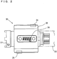
- the transmitting unit 20 can be arranged on the tightening torque measuring unit 30 as shown in FIG. 2 .
- the transmitting unit 20 has a transmitting circuit 22 (RF circuit) for transmitting/receiving signals, and a plurality of transmitting antennas 24, 25 for transmitting/receiving.
- RF circuit RF circuit
- a power can be supplied to the transmitting unit 20 by a battery not shown.
- the transmitting unit 20 can be housed in a suitable place in a tubular casing 35 of the tightening torque measuring unit 30, described later. As shown in FIG. 2 , it is desirable that the transmitting antenna 1 (24) and the transmitting antenna 2 (25) are arranged near an outer periphery of the casing 35 at a predetermined interval. In this embodiment, they are arranged so as to be opposed to each other via a shaft center. Further, they are arranged at opposing corners so as to be separated by 1/2 or more wavelength of a wireless communication frequency used by the adjacent antennas.
- Any one of the transmitting antennas 24, 25 is selected so as to be electrically connected to the transmitting circuit 22 via an antenna switch 23.
- the transmitting circuit 22 and the antenna switch 23 are controlled by a transmitting controller 21.
- the transmitting controller 21 can be constituted by a CPU, a memory or the like.
- the transmitting controller 21 processes an output from a detection sensor 31 described later, processes various signals transmitted from the transmitting circuit 22, measures, stores and compares received signal intensities of return signals received via the transmitting antennas 24, 25.
- the transmitting controller 21 selects the transmitting antenna 24 or 25 and operates the antenna switch 23 so as to switch the transmitting antenna 24 or 25 that should transmit a signal.
- a signal transmitted from the transmitting circuit 22 a signal including a return request and/or tightening information detected by the detection sensor 31, described later, can be exemplified.
- the tightening torque measuring unit 30 on which the transmitting unit 20 is arranged is, as shown in FIG. 2 , mounted to the rotating shaft 50 of the tightening machine in a detachable or fixed manner.
- the tightening torque measuring unit 30 has an outer periphery surrounded by the casing 35, and has the transmitting unit 20 arranged inside.
- the tightening torque measuring unit 30 has the detection sensor 31 for electrically detecting a torque applied to the rotating shaft 50, an amplifier 32 for amplifying the tightening information output from the detection sensor, and an A/D converter 33 for A/D-converting the amplified tightening information.
- the tightening information converted into a digital signal by the A/D converter 33 is transmitted to the transmitting controller 21.
- the detection sensor 31 for measuring information about tightening when a tightening torque is measured as the tightening information, a strain gauge can be exemplified. Further, when information about the rotating angle is measured as the tightening information, an encoder, a gyro sensor, a photo interrupter, or a magnetic sensor can be exemplified. When the detection sensor 31 outputs a digital signal like an encoder or a photo interrupter, the A/D converter 33 can be omitted.
- the detection sensor 31 is not limited to the above, but various devices can be surely used.
- the tightening torque measuring unit 30 can be driven by a battery (not shown) arranged in the casing 35 as a power supply.
- the battery may be shared by the transmitting unit 20.
- a display unit 36 may be arranged on the tightening torque measuring unit 30 as shown in FIG. 2 , so that the tightening information can be visually recognized in a direct manner.
- a signal transmitted from the transmitting unit 20 can be received by a receiving unit 40 shown in FIG. 1 .
- the receiving unit 40 has a receiving antenna 43, a receiving circuit 42 (RF circuit) and a receiving controller 41.
- a signal transmitted from the transmitting unit 20 is received by the receiving controller 41 via the receiving antenna 43 and the receiving circuit 42.
- the receiving controller 41 Every time the receiving controller 41 receives a signal including a return request in a receiving standby state, it transmits a return signal including an RSSI value (received signal intensity value) from the receiving circuit 42 via the receiving antenna 43.
- RSSI value received signal intensity value
- the receiving controller 41 incorporates a memory (not shown) or is connected to a display unit 45, the received tightening information can be stored in the memory or can be suitably displayed on the display unit 45.
- a device identification number of the tightening torque measuring unit 30, a time, and position information such as a tightening position are included in the signal about the tightening information transmitted from the transmitting unit 20. This can be used for display and management of the tightening information on the receiving side.
- the receiving unit 40 and the display unit 45 can be driven by a commercial power supply or a battery as a power supply.
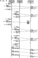
- a front end socket 51 of the rotating shaft 50 of the tightening machine is fitted into a bolt or a nut and started to be tightened.
- the detection sensor 31 detects a torque applied to the rotating shaft 50, the amplifier 32 amplifies the torque, and the A/D converter 33 A/D-converts the torque.
- the converted torque is transmitted to the transmitting controller 21 (step 1).
- the transmitting controller 21 does not transmit a torque value from the transmitting circuit 22 until the tightening information detected by the detection sensor 31 satisfies a predetermined condition, in this embodiment, until the torque value becomes a predetermined threshold or more. (step 1). This is because when the torque value is the predetermined threshold or less, the rotating shaft 50 rotates, and a position of the tightening torque measuring unit 30, namely, positions of the transmitting antennas 24, 25 in a rotating direction are not fixed.
- step 1 When the tightening proceeds, the torque rises and exceeds the predetermined threshold (step 1), the rotating shaft 50 of the tightening machine hardly rotates, and the tightening torque measuring unit 30 attached to the rotating shaft 50 and the position in the rotating direction are approximately fixed. Therefore, the positions of the transmitting antennas 24, 25 are unmoving.
- the transmitting controller 21 operates the antenna switch 23 so as to set any one of the transmitting antennas 24, 25 to be connected to the transmitting circuit 22 (step 2, action 1: for example, the transmitting antenna 1 (24) is connected to the transmitting circuit 22). In this state, the signal is not yet transmitted.
- the transmitting controller 21 In the state that the transmitting antenna 1 (24) is connected to the transmitting circuit 22, the transmitting controller 21 resets each RSSI integrated value to be retained to zero.
- a received signal intensity integrated value on the transmitting antenna 1 (24) is determined as an RSSI1
- a received signal intensity integrated value on the transmitting antenna 2 (25) is determined as an RSSI 2.
- a torque value is sequentially input into the transmitting controller 21 at every predetermined time (step 4).
- a predetermined measured value transmitting timing comes (step 5) and the transmitting antennas 24, 25 are not fixed (steps 16 and 17, described later) (step 6)
- the transmitting controller 21 transmits the signal including the return request and the torque value from the transmitting circuit 22 via the transmitting antenna 1 (24) (step 8, action 2).
- measurement of RSSI of each of the transmitting antennas 24, 25 (a received signal intensity measuring step) is started.
- timing at which the torque value is input at the predetermined number of times (for example, 10 times) can be exemplified.
- the receiving controller 41 When the receiving unit 40 receives the signal including the return request (action 3), the receiving controller 41 returns a signal (return signal) including the received signal intensity value (RSSI) from the receiving circuit 42 via the receiving antenna 43 (action 4).
- the transmitting unit 20 When the transmitting unit 20 receives the returns signal via the receiving antenna 24 (step 9, action 5), it updates the RSSI integrated value (RSSI1) of an antenna number of the transmitting antenna that transmits the signal (in this case, the transmitting antenna 1 (24)) (step 11).
- the RSSI1 is calculated by multiplying a value of original RSSI1 (at first, zero) by the received RSSI.
- the transmitting controller 21 When the return signal is received within a predetermined time and the sum of the RSSI values of both the transmitting antennas 24, 25 is the predetermined threshold or less (step 13) or when the return signal is not received (step 9), the transmitting controller 21 operates the antenna switch 23 so as to switch the transmitting antenna from the transmitting antenna 1 (24) to the transmitting antenna 2 (25) (step 15, action 6).
- the tightening information is sequentially input into the transmitting controller 21 at every predetermined time similarly to the above (step 4), and when the predetermined measured value transmitting timing comes (step 5), the tightening information and the signal including the return request are transmitted from the transmitting circuit 22 via the transmitting antenna 2 (25) (step 8, action 7).
- the receiving controller 41 When the receiving unit 40 receives the signal including the return request (action 8), the receiving controller 41 returns a signal including a received signal intensity value (RSSI) (return signal) from the receiving circuit 42 via the receiving antenna 43 (action 9).
- RSSI received signal intensity value
- the transmitting unit 20 When the transmitting unit 20 receives the return signal via the transmitting antenna 2 (25) (step 9, action 10, it updates the RSSI integrated value (RSSI 2) of the transmitting antenna 2 (25) (step 11).
- the RSSI 2 is calculated by multiplying a value of original RSSI 2 (at first, zero) by the received RSSI.
- the transmitting controller 21 operates the antenna switch 23) so as to again switch the transmitting antenna from the transmitting antenna 2 (25) to the transmitting antenna 1 (24) (step 15, action 11).
- the transmitting controller 21 compares the RSSI values of both the transmitting antennas 24, 25 (step 14, action 25). The transmitting controller 21 selects the transmitting antenna 24 or 25 whose RSSI value is larger and operates the antenna switch 23 so as to fix the transmitting antenna 24 or 25 (steps 16 and 17, action 26).
- the transmitting antenna 2 (25) when the transmitting antenna 2 (25) is selected and fixed, the transmitting thereafter is performed from the transmitting antenna 2 (25) (steps 6 and 7). After the transmitting antenna is fixed, the signal transmitted from the transmitting unit 20 may not include the return request (actions 27 to 32).
- the receiving unit 40 receives a signal including a torque value transmitted from the transmitting unit 20, and stores it in the memory or displays it on the display unit 45.
- the number of the transmitting antenna and the RSSI value may be also displayed together.
- step 1 When the torque value does not fluctuate for predetermined time or the torque value that once rises reduces after its peak, a determination is made that one tightening operation is completed, and the transmitting of the signal including the torque value may be stopped. When new tightening is performed and the torque value becomes the predetermined threshold or more (step 1), the above flow is again performed.
- the step of measuring the received signal intensity is performed at step 13 under the condition that the step is repeated until the sum of the RSSI integrated values of the two antennas becomes larger than the predetermined threshold (actions 1 to 24).
- the step of measuring the received signal intensity can be performed once or can be performed until any one of the RSSI values becomes the predetermined threshold or more.
- the number of times at which the step of measuring the received signal intensity is performed is determined, and at a stage that the step is performed at that number of times, the transmitting antenna whose RSSI integrate value is the highest may be selected and fixed.
- the signals are sequentially transmitted/received to/from the individual transmitting antennas until the transmitting antenna wherein the received signal intensity is the highest is selected from the plurality of transmitting antennas.
- the transmitting antenna is once selected, the signal can be transmitted from the transmitting antenna in a fixed manner. For this reason, establishment of the communication state can be accelerated, the battery consumption can be reduced, and the share of a wireless frequency space can be cut down.
- the receiving unit 40 wirelessly communicates with one transmitting unit 20, but a system that wirelessly communicates with the plurality of transmitting units 40 and transmits/receives signals including RSSI can be constituted.
- a constitution may be such that a plurality of receiving antennas 23 are provided to the receiving unit 40 and a combination of the receiving antenna 23 wherein the receiving quality is the highest and the transmitting antennas 24, 25 is selected by the method similar to the transmitting unit 20.
- the present invention is useful as the antenna switching method of the wireless communication system having the plurality of transmitting antennas.
Landscapes
- Engineering & Computer Science (AREA)
- Computer Networks & Wireless Communication (AREA)
- Signal Processing (AREA)
- Radio Transmission System (AREA)
- Arrangements For Transmission Of Measured Signals (AREA)
- Mobile Radio Communication Systems (AREA)
Applications Claiming Priority (1)
| Application Number | Priority Date | Filing Date | Title |
|---|---|---|---|
| JP2009253790A JP5356185B2 (ja) | 2009-11-05 | 2009-11-05 | 無線通信システムのアンテナ切替方法 |
Publications (3)
| Publication Number | Publication Date |
|---|---|
| EP2320577A2 EP2320577A2 (en) | 2011-05-11 |
| EP2320577A3 EP2320577A3 (en) | 2012-06-06 |
| EP2320577B1 true EP2320577B1 (en) | 2018-01-03 |
Family
ID=43479893
Family Applications (1)
| Application Number | Title | Priority Date | Filing Date |
|---|---|---|---|
| EP10014297.5A Active EP2320577B1 (en) | 2009-11-05 | 2010-11-04 | Antenna switching method of wireless communication system |
Country Status (7)
| Country | Link |
|---|---|
| US (1) | US8200287B2 (enExample) |
| EP (1) | EP2320577B1 (enExample) |
| JP (1) | JP5356185B2 (enExample) |
| KR (1) | KR101750561B1 (enExample) |
| CN (1) | CN102055511B (enExample) |
| CA (1) | CA2720059C (enExample) |
| TW (1) | TWI481214B (enExample) |
Families Citing this family (12)
| Publication number | Priority date | Publication date | Assignee | Title |
|---|---|---|---|---|
| JP6048875B2 (ja) * | 2012-02-14 | 2016-12-21 | パナソニックIpマネジメント株式会社 | 無線通信システム |
| CN103378887B (zh) * | 2012-04-20 | 2017-08-25 | 南京中兴新软件有限责任公司 | 射频信号的发送、接收装置及方法 |
| ITMI20130495A1 (it) * | 2013-03-29 | 2014-09-30 | Atlas Copco Blm Srl | Dispositivo elettronico di controllo e comando per sensori |
| TWI572088B (zh) * | 2013-09-14 | 2017-02-21 | 瑞昱半導體股份有限公司 | 無線通訊裝置及其控制方法 |
| US9893715B2 (en) * | 2013-12-09 | 2018-02-13 | Shure Acquisition Holdings, Inc. | Adaptive self-tunable antenna system and method |
| KR20160007720A (ko) | 2014-06-25 | 2016-01-21 | 엘지이노텍 주식회사 | 무선전력전송 송신 장치 |
| CN104218964B (zh) * | 2014-09-04 | 2016-06-29 | 青岛海信移动通信技术股份有限公司 | 一种移动终端及Wi-Fi天线控制方法 |
| CN108649990A (zh) * | 2018-03-29 | 2018-10-12 | 努比亚技术有限公司 | 射频干扰处理方法及移动终端 |
| JP7354810B2 (ja) * | 2019-12-04 | 2023-10-03 | 株式会社デンソー | 通信システム |
| WO2022038890A1 (ja) * | 2020-08-17 | 2022-02-24 | ソニーセミコンダクタソリューションズ株式会社 | 通信装置、通信システムおよび鍵開閉制御方法 |
| CN113183073B (zh) * | 2021-06-03 | 2025-01-21 | 国网河南省电力公司电力科学研究院 | 一种带无线传输功能的电动拧紧扳手及其使用方法 |
| CN115276691A (zh) | 2021-10-14 | 2022-11-01 | 神基科技股份有限公司 | 无线信号接收装置及系统 |
Family Cites Families (15)
| Publication number | Priority date | Publication date | Assignee | Title |
|---|---|---|---|---|
| US5561673A (en) * | 1993-04-16 | 1996-10-01 | Matsushita Electric Industrial Co., Ltd. | Antenna switched diversity reciever |
| JP2751869B2 (ja) * | 1995-04-28 | 1998-05-18 | 日本電気株式会社 | 送信ダイバシティ方式 |
| US6034643A (en) * | 1997-03-28 | 2000-03-07 | Kabushiki Kaisha Toyota Chuo Kenkyusho | Directional beam antenna device and directional beam controlling apparatus |
| JPH10276124A (ja) * | 1997-03-28 | 1998-10-13 | Hitachi Ltd | 無線通信網 |
| JP2002026796A (ja) * | 1998-04-07 | 2002-01-25 | Matsushita Electric Ind Co Ltd | 無線通信装置及び無線通信システム |
| JP2000353998A (ja) | 1999-06-11 | 2000-12-19 | Matsushita Electric Ind Co Ltd | ダイバーシティ受信機およびダイバーシティ送信機 |
| JP2002239939A (ja) * | 2001-02-19 | 2002-08-28 | Hitachi Engineering & Services Co Ltd | ボルトの締付けトルク管理装置 |
| US7103382B2 (en) * | 2001-07-10 | 2006-09-05 | Kyocera Wireless Corp. | System and method for receiving and transmitting information in a multipath environment |
| DE10317689A1 (de) * | 2003-04-17 | 2004-10-28 | Robert Bosch Gmbh | HF-Felgenantenne mit mehreren Patch-Antennen |
| JP3975299B2 (ja) * | 2004-07-08 | 2007-09-12 | 前田金属工業株式会社 | 締付トルク測定ユニット及びトルク表示締付機 |
| GB0511458D0 (en) * | 2005-06-06 | 2005-07-13 | Melexis Nv | Monitoring device for a rotatable shaft |
| JP4079196B2 (ja) * | 2005-12-21 | 2008-04-23 | 松下電器産業株式会社 | 無線警報装置およびそのプログラム |
| JP2009033486A (ja) * | 2007-07-27 | 2009-02-12 | Panasonic Corp | 無線通信装置 |
| US9246541B2 (en) * | 2008-02-01 | 2016-01-26 | Qualcomm Incorporated | UTRAN enhancements for the support of inter-cell interference cancellation |
| JP2009212691A (ja) * | 2008-03-03 | 2009-09-17 | Fujitsu Ltd | 複数のアンテナを使用して無線信号を送信する方法および装置 |
-
2009
- 2009-11-05 JP JP2009253790A patent/JP5356185B2/ja active Active
-
2010
- 2010-10-26 US US12/911,898 patent/US8200287B2/en active Active
- 2010-11-02 TW TW099137627A patent/TWI481214B/zh active
- 2010-11-03 CN CN201010535067.7A patent/CN102055511B/zh active Active
- 2010-11-04 KR KR1020100109223A patent/KR101750561B1/ko active Active
- 2010-11-04 CA CA2720059A patent/CA2720059C/en active Active
- 2010-11-04 EP EP10014297.5A patent/EP2320577B1/en active Active
Non-Patent Citations (1)
| Title |
|---|
| None * |
Also Published As
| Publication number | Publication date |
|---|---|
| HK1157951A1 (en) | 2012-07-06 |
| EP2320577A3 (en) | 2012-06-06 |
| US8200287B2 (en) | 2012-06-12 |
| KR101750561B1 (ko) | 2017-06-23 |
| CN102055511B (zh) | 2015-02-18 |
| EP2320577A2 (en) | 2011-05-11 |
| KR20110049731A (ko) | 2011-05-12 |
| CA2720059C (en) | 2017-10-24 |
| JP5356185B2 (ja) | 2013-12-04 |
| JP2011101153A (ja) | 2011-05-19 |
| CA2720059A1 (en) | 2011-05-05 |
| CN102055511A (zh) | 2011-05-11 |
| TW201125306A (en) | 2011-07-16 |
| TWI481214B (zh) | 2015-04-11 |
| US20110105038A1 (en) | 2011-05-05 |
Similar Documents
| Publication | Publication Date | Title |
|---|---|---|
| EP2320577B1 (en) | Antenna switching method of wireless communication system | |
| US8095159B2 (en) | Radio power-fed terminal, system, and method | |
| US9234929B2 (en) | Monitoring method and system and integrated monitoring device for antenna oscillator of base station | |
| US8874045B2 (en) | RF circuit and isolation detecting device thereof, and method for measuring a degree of isolation between a first RF circuit and a second RF circuit with respect to a frequency | |
| KR101636686B1 (ko) | 비콘신호와 다중빔 안테나를 이용한 광대역 무선 고속데이터 송수신장치 및 안테나 빔방향 선택방법 | |
| US9312956B2 (en) | Fiber-optic communication apparatus capable of operating in a normal mode and a power calibration mode, and communication device used within the same | |
| US20040214595A1 (en) | Antenna gain specifying device and radio communication device | |
| KR102673505B1 (ko) | 안테나 장치 및 이의 전력공급방법 | |
| US20260032474A1 (en) | Network measurement device with combined receivers | |
| US20060240816A1 (en) | Wireless phone system | |
| KR20210021807A (ko) | 안테나모니터링시스템 및 이의 동작방법 | |
| EP2755337A1 (en) | Monitoring method and system and integrated monitoring device for antenna oscillator of base station | |
| CN211717489U (zh) | 多路传感器标定测量装置 | |
| JP4418440B2 (ja) | 無線通信装置 | |
| HK1157951B (en) | Antenna switching method of wireless communicaton system | |
| JP2003276410A (ja) | タイヤ状態監視装置 | |
| JP2000039460A (ja) | 無線装置の評価方法 | |
| JP6278303B2 (ja) | アンテナ切替システム | |
| JP5007283B2 (ja) | 無線監視システム | |
| US20230017393A1 (en) | Tire pressure detection system with separated antennas | |
| KR101813970B1 (ko) | 지상파 디지털 방송용 rf 송신장비를 설정제어·모니터링시키는 1:n 방식형 스마트 원격제어형성장치 | |
| KR20030053981A (ko) | 이동통신 단말기에서의 안테나 이득 조절장치 및 방법 | |
| JP2016141270A (ja) | タイヤ空気圧検知システム | |
| ES2415366T3 (es) | Sistema de monitorización y control de dispositivos de medición de señales de telecomunicación | |
| JP2008166866A (ja) | 基地局アンテナのキャリブレーション方法、及び通信基地局 |
Legal Events
| Date | Code | Title | Description |
|---|---|---|---|
| PUAI | Public reference made under article 153(3) epc to a published international application that has entered the european phase |
Free format text: ORIGINAL CODE: 0009012 |
|
| AK | Designated contracting states |
Kind code of ref document: A2 Designated state(s): AL AT BE BG CH CY CZ DE DK EE ES FI FR GB GR HR HU IE IS IT LI LT LU LV MC MK MT NL NO PL PT RO RS SE SI SK SM TR |
|
| AX | Request for extension of the european patent |
Extension state: BA ME |
|
| PUAL | Search report despatched |
Free format text: ORIGINAL CODE: 0009013 |
|
| AK | Designated contracting states |
Kind code of ref document: A3 Designated state(s): AL AT BE BG CH CY CZ DE DK EE ES FI FR GB GR HR HU IE IS IT LI LT LU LV MC MK MT NL NO PL PT RO RS SE SI SK SM TR |
|
| AX | Request for extension of the european patent |
Extension state: BA ME |
|
| RIC1 | Information provided on ipc code assigned before grant |
Ipc: H04B 7/06 20060101AFI20120501BHEP |
|
| 17P | Request for examination filed |
Effective date: 20121205 |
|
| 17Q | First examination report despatched |
Effective date: 20151104 |
|
| GRAP | Despatch of communication of intention to grant a patent |
Free format text: ORIGINAL CODE: EPIDOSNIGR1 |
|
| INTG | Intention to grant announced |
Effective date: 20170614 |
|
| GRAS | Grant fee paid |
Free format text: ORIGINAL CODE: EPIDOSNIGR3 |
|
| GRAJ | Information related to disapproval of communication of intention to grant by the applicant or resumption of examination proceedings by the epo deleted |
Free format text: ORIGINAL CODE: EPIDOSDIGR1 |
|
| GRAL | Information related to payment of fee for publishing/printing deleted |
Free format text: ORIGINAL CODE: EPIDOSDIGR3 |
|
| GRAR | Information related to intention to grant a patent recorded |
Free format text: ORIGINAL CODE: EPIDOSNIGR71 |
|
| INTC | Intention to grant announced (deleted) | ||
| GRAA | (expected) grant |
Free format text: ORIGINAL CODE: 0009210 |
|
| INTG | Intention to grant announced |
Effective date: 20171114 |
|
| AK | Designated contracting states |
Kind code of ref document: B1 Designated state(s): AL AT BE BG CH CY CZ DE DK EE ES FI FR GB GR HR HU IE IS IT LI LT LU LV MC MK MT NL NO PL PT RO RS SE SI SK SM TR |
|
| REG | Reference to a national code |
Ref country code: GB Ref legal event code: FG4D |
|
| REG | Reference to a national code |
Ref country code: CH Ref legal event code: EP Ref country code: AT Ref legal event code: REF Ref document number: 961158 Country of ref document: AT Kind code of ref document: T Effective date: 20180115 |
|
| REG | Reference to a national code |
Ref country code: IE Ref legal event code: FG4D |
|
| REG | Reference to a national code |
Ref country code: DE Ref legal event code: R096 Ref document number: 602010047734 Country of ref document: DE |
|
| REG | Reference to a national code |
Ref country code: NL Ref legal event code: MP Effective date: 20180103 |
|
| REG | Reference to a national code |
Ref country code: LT Ref legal event code: MG4D |
|
| REG | Reference to a national code |
Ref country code: AT Ref legal event code: MK05 Ref document number: 961158 Country of ref document: AT Kind code of ref document: T Effective date: 20180103 |
|
| PG25 | Lapsed in a contracting state [announced via postgrant information from national office to epo] |
Ref country code: NL Free format text: LAPSE BECAUSE OF FAILURE TO SUBMIT A TRANSLATION OF THE DESCRIPTION OR TO PAY THE FEE WITHIN THE PRESCRIBED TIME-LIMIT Effective date: 20180103 |
|
| PG25 | Lapsed in a contracting state [announced via postgrant information from national office to epo] |
Ref country code: ES Free format text: LAPSE BECAUSE OF FAILURE TO SUBMIT A TRANSLATION OF THE DESCRIPTION OR TO PAY THE FEE WITHIN THE PRESCRIBED TIME-LIMIT Effective date: 20180103 Ref country code: HR Free format text: LAPSE BECAUSE OF FAILURE TO SUBMIT A TRANSLATION OF THE DESCRIPTION OR TO PAY THE FEE WITHIN THE PRESCRIBED TIME-LIMIT Effective date: 20180103 Ref country code: LT Free format text: LAPSE BECAUSE OF FAILURE TO SUBMIT A TRANSLATION OF THE DESCRIPTION OR TO PAY THE FEE WITHIN THE PRESCRIBED TIME-LIMIT Effective date: 20180103 Ref country code: FI Free format text: LAPSE BECAUSE OF FAILURE TO SUBMIT A TRANSLATION OF THE DESCRIPTION OR TO PAY THE FEE WITHIN THE PRESCRIBED TIME-LIMIT Effective date: 20180103 Ref country code: CY Free format text: LAPSE BECAUSE OF FAILURE TO SUBMIT A TRANSLATION OF THE DESCRIPTION OR TO PAY THE FEE WITHIN THE PRESCRIBED TIME-LIMIT Effective date: 20180103 Ref country code: NO Free format text: LAPSE BECAUSE OF FAILURE TO SUBMIT A TRANSLATION OF THE DESCRIPTION OR TO PAY THE FEE WITHIN THE PRESCRIBED TIME-LIMIT Effective date: 20180403 |
|
| PG25 | Lapsed in a contracting state [announced via postgrant information from national office to epo] |
Ref country code: LV Free format text: LAPSE BECAUSE OF FAILURE TO SUBMIT A TRANSLATION OF THE DESCRIPTION OR TO PAY THE FEE WITHIN THE PRESCRIBED TIME-LIMIT Effective date: 20180103 Ref country code: SE Free format text: LAPSE BECAUSE OF FAILURE TO SUBMIT A TRANSLATION OF THE DESCRIPTION OR TO PAY THE FEE WITHIN THE PRESCRIBED TIME-LIMIT Effective date: 20180103 Ref country code: PL Free format text: LAPSE BECAUSE OF FAILURE TO SUBMIT A TRANSLATION OF THE DESCRIPTION OR TO PAY THE FEE WITHIN THE PRESCRIBED TIME-LIMIT Effective date: 20180103 Ref country code: GR Free format text: LAPSE BECAUSE OF FAILURE TO SUBMIT A TRANSLATION OF THE DESCRIPTION OR TO PAY THE FEE WITHIN THE PRESCRIBED TIME-LIMIT Effective date: 20180404 Ref country code: IS Free format text: LAPSE BECAUSE OF FAILURE TO SUBMIT A TRANSLATION OF THE DESCRIPTION OR TO PAY THE FEE WITHIN THE PRESCRIBED TIME-LIMIT Effective date: 20180503 Ref country code: AT Free format text: LAPSE BECAUSE OF FAILURE TO SUBMIT A TRANSLATION OF THE DESCRIPTION OR TO PAY THE FEE WITHIN THE PRESCRIBED TIME-LIMIT Effective date: 20180103 Ref country code: BG Free format text: LAPSE BECAUSE OF FAILURE TO SUBMIT A TRANSLATION OF THE DESCRIPTION OR TO PAY THE FEE WITHIN THE PRESCRIBED TIME-LIMIT Effective date: 20180403 Ref country code: RS Free format text: LAPSE BECAUSE OF FAILURE TO SUBMIT A TRANSLATION OF THE DESCRIPTION OR TO PAY THE FEE WITHIN THE PRESCRIBED TIME-LIMIT Effective date: 20180103 |
|
| REG | Reference to a national code |
Ref country code: DE Ref legal event code: R097 Ref document number: 602010047734 Country of ref document: DE |
|
| PG25 | Lapsed in a contracting state [announced via postgrant information from national office to epo] |
Ref country code: EE Free format text: LAPSE BECAUSE OF FAILURE TO SUBMIT A TRANSLATION OF THE DESCRIPTION OR TO PAY THE FEE WITHIN THE PRESCRIBED TIME-LIMIT Effective date: 20180103 Ref country code: RO Free format text: LAPSE BECAUSE OF FAILURE TO SUBMIT A TRANSLATION OF THE DESCRIPTION OR TO PAY THE FEE WITHIN THE PRESCRIBED TIME-LIMIT Effective date: 20180103 Ref country code: IT Free format text: LAPSE BECAUSE OF FAILURE TO SUBMIT A TRANSLATION OF THE DESCRIPTION OR TO PAY THE FEE WITHIN THE PRESCRIBED TIME-LIMIT Effective date: 20180103 Ref country code: AL Free format text: LAPSE BECAUSE OF FAILURE TO SUBMIT A TRANSLATION OF THE DESCRIPTION OR TO PAY THE FEE WITHIN THE PRESCRIBED TIME-LIMIT Effective date: 20180103 |
|
| PLBE | No opposition filed within time limit |
Free format text: ORIGINAL CODE: 0009261 |
|
| STAA | Information on the status of an ep patent application or granted ep patent |
Free format text: STATUS: NO OPPOSITION FILED WITHIN TIME LIMIT |
|
| PG25 | Lapsed in a contracting state [announced via postgrant information from national office to epo] |
Ref country code: SM Free format text: LAPSE BECAUSE OF FAILURE TO SUBMIT A TRANSLATION OF THE DESCRIPTION OR TO PAY THE FEE WITHIN THE PRESCRIBED TIME-LIMIT Effective date: 20180103 Ref country code: DK Free format text: LAPSE BECAUSE OF FAILURE TO SUBMIT A TRANSLATION OF THE DESCRIPTION OR TO PAY THE FEE WITHIN THE PRESCRIBED TIME-LIMIT Effective date: 20180103 Ref country code: CZ Free format text: LAPSE BECAUSE OF FAILURE TO SUBMIT A TRANSLATION OF THE DESCRIPTION OR TO PAY THE FEE WITHIN THE PRESCRIBED TIME-LIMIT Effective date: 20180103 Ref country code: SK Free format text: LAPSE BECAUSE OF FAILURE TO SUBMIT A TRANSLATION OF THE DESCRIPTION OR TO PAY THE FEE WITHIN THE PRESCRIBED TIME-LIMIT Effective date: 20180103 |
|
| 26N | No opposition filed |
Effective date: 20181005 |
|
| PG25 | Lapsed in a contracting state [announced via postgrant information from national office to epo] |
Ref country code: SI Free format text: LAPSE BECAUSE OF FAILURE TO SUBMIT A TRANSLATION OF THE DESCRIPTION OR TO PAY THE FEE WITHIN THE PRESCRIBED TIME-LIMIT Effective date: 20180103 |
|
| REG | Reference to a national code |
Ref country code: CH Ref legal event code: PL |
|
| PG25 | Lapsed in a contracting state [announced via postgrant information from national office to epo] |
Ref country code: MC Free format text: LAPSE BECAUSE OF FAILURE TO SUBMIT A TRANSLATION OF THE DESCRIPTION OR TO PAY THE FEE WITHIN THE PRESCRIBED TIME-LIMIT Effective date: 20180103 Ref country code: LU Free format text: LAPSE BECAUSE OF NON-PAYMENT OF DUE FEES Effective date: 20181104 |
|
| REG | Reference to a national code |
Ref country code: BE Ref legal event code: MM Effective date: 20181130 |
|
| REG | Reference to a national code |
Ref country code: IE Ref legal event code: MM4A |
|
| PG25 | Lapsed in a contracting state [announced via postgrant information from national office to epo] |
Ref country code: LI Free format text: LAPSE BECAUSE OF NON-PAYMENT OF DUE FEES Effective date: 20181130 Ref country code: CH Free format text: LAPSE BECAUSE OF NON-PAYMENT OF DUE FEES Effective date: 20181130 |
|
| PG25 | Lapsed in a contracting state [announced via postgrant information from national office to epo] |
Ref country code: IE Free format text: LAPSE BECAUSE OF NON-PAYMENT OF DUE FEES Effective date: 20181104 |
|
| PG25 | Lapsed in a contracting state [announced via postgrant information from national office to epo] |
Ref country code: BE Free format text: LAPSE BECAUSE OF NON-PAYMENT OF DUE FEES Effective date: 20181130 |
|
| PG25 | Lapsed in a contracting state [announced via postgrant information from national office to epo] |
Ref country code: MT Free format text: LAPSE BECAUSE OF NON-PAYMENT OF DUE FEES Effective date: 20181104 |
|
| PG25 | Lapsed in a contracting state [announced via postgrant information from national office to epo] |
Ref country code: TR Free format text: LAPSE BECAUSE OF FAILURE TO SUBMIT A TRANSLATION OF THE DESCRIPTION OR TO PAY THE FEE WITHIN THE PRESCRIBED TIME-LIMIT Effective date: 20180103 |
|
| PG25 | Lapsed in a contracting state [announced via postgrant information from national office to epo] |
Ref country code: PT Free format text: LAPSE BECAUSE OF FAILURE TO SUBMIT A TRANSLATION OF THE DESCRIPTION OR TO PAY THE FEE WITHIN THE PRESCRIBED TIME-LIMIT Effective date: 20180103 |
|
| PG25 | Lapsed in a contracting state [announced via postgrant information from national office to epo] |
Ref country code: MK Free format text: LAPSE BECAUSE OF NON-PAYMENT OF DUE FEES Effective date: 20180103 Ref country code: HU Free format text: LAPSE BECAUSE OF FAILURE TO SUBMIT A TRANSLATION OF THE DESCRIPTION OR TO PAY THE FEE WITHIN THE PRESCRIBED TIME-LIMIT; INVALID AB INITIO Effective date: 20101104 |
|
| PGFP | Annual fee paid to national office [announced via postgrant information from national office to epo] |
Ref country code: DE Payment date: 20251126 Year of fee payment: 16 |
|
| PGFP | Annual fee paid to national office [announced via postgrant information from national office to epo] |
Ref country code: GB Payment date: 20251120 Year of fee payment: 16 |
|
| PGFP | Annual fee paid to national office [announced via postgrant information from national office to epo] |
Ref country code: FR Payment date: 20251125 Year of fee payment: 16 |