EP2320488A1 - Convertisseur électromécanique avec un élastomère diélectrique - Google Patents
Convertisseur électromécanique avec un élastomère diélectrique Download PDFInfo
- Publication number
- EP2320488A1 EP2320488A1 EP09013987A EP09013987A EP2320488A1 EP 2320488 A1 EP2320488 A1 EP 2320488A1 EP 09013987 A EP09013987 A EP 09013987A EP 09013987 A EP09013987 A EP 09013987A EP 2320488 A1 EP2320488 A1 EP 2320488A1
- Authority
- EP
- European Patent Office
- Prior art keywords
- magnet
- layer
- magnets
- dielectric elastomer
- ring
- Prior art date
- Legal status (The legal status is an assumption and is not a legal conclusion. Google has not performed a legal analysis and makes no representation as to the accuracy of the status listed.)
- Withdrawn
Links
Images


Classifications
-
- F—MECHANICAL ENGINEERING; LIGHTING; HEATING; WEAPONS; BLASTING
- F16—ENGINEERING ELEMENTS AND UNITS; GENERAL MEASURES FOR PRODUCING AND MAINTAINING EFFECTIVE FUNCTIONING OF MACHINES OR INSTALLATIONS; THERMAL INSULATION IN GENERAL
- F16K—VALVES; TAPS; COCKS; ACTUATING-FLOATS; DEVICES FOR VENTING OR AERATING
- F16K31/00—Actuating devices; Operating means; Releasing devices
- F16K31/02—Actuating devices; Operating means; Releasing devices electric; magnetic
- F16K31/06—Actuating devices; Operating means; Releasing devices electric; magnetic using a magnet, e.g. diaphragm valves, cutting off by means of a liquid
- F16K31/08—Actuating devices; Operating means; Releasing devices electric; magnetic using a magnet, e.g. diaphragm valves, cutting off by means of a liquid using a permanent magnet
-
- G—PHYSICS
- G09—EDUCATION; CRYPTOGRAPHY; DISPLAY; ADVERTISING; SEALS
- G09B—EDUCATIONAL OR DEMONSTRATION APPLIANCES; APPLIANCES FOR TEACHING, OR COMMUNICATING WITH, THE BLIND, DEAF OR MUTE; MODELS; PLANETARIA; GLOBES; MAPS; DIAGRAMS
- G09B21/00—Teaching, or communicating with, the blind, deaf or mute
- G09B21/001—Teaching or communicating with blind persons
- G09B21/003—Teaching or communicating with blind persons using tactile presentation of the information, e.g. Braille displays
- G09B21/004—Details of particular tactile cells, e.g. electro-mechanical or mechanical layout
-
- H—ELECTRICITY
- H10—SEMICONDUCTOR DEVICES; ELECTRIC SOLID-STATE DEVICES NOT OTHERWISE PROVIDED FOR
- H10N—ELECTRIC SOLID-STATE DEVICES NOT OTHERWISE PROVIDED FOR
- H10N30/00—Piezoelectric or electrostrictive devices
- H10N30/20—Piezoelectric or electrostrictive devices with electrical input and mechanical output, e.g. functioning as actuators or vibrators
- H10N30/206—Piezoelectric or electrostrictive devices with electrical input and mechanical output, e.g. functioning as actuators or vibrators using only longitudinal or thickness displacement, e.g. d33 or d31 type devices
-
- H—ELECTRICITY
- H10—SEMICONDUCTOR DEVICES; ELECTRIC SOLID-STATE DEVICES NOT OTHERWISE PROVIDED FOR
- H10N—ELECTRIC SOLID-STATE DEVICES NOT OTHERWISE PROVIDED FOR
- H10N30/00—Piezoelectric or electrostrictive devices
- H10N30/80—Constructional details
- H10N30/88—Mounts; Supports; Enclosures; Casings
- H10N30/886—Mechanical prestressing means, e.g. springs
Definitions
- the present invention relates to an electromechanical transducer comprising a dielectric elastomer to which a force is applied via magnets. It further relates to the use of transducers according to the invention in tactile display elements and for controlling fluid flows.
- tactile and kinesthetic perception The sense of touch of man consists of two components. These are the tactile and kinesthetic perception. Distinguishing both perceptions is of great importance to the engineer when formulating the requirements for a tactile-responsive system. So “tactile” means the interaction of the system with the skin, that is, the palpation of geometric shapes. In contrast, “kinesthetic” refers to the actuatoric and sensory properties of muscles and joints, and therefore refers to forces, moments, positions, and angles.
- tactile displays which generate either static patterns, which are scanned by the user or dynamic patterns that arise without relative movement between the finger and the surface of the tactile display device.
- tactile display elements can convert visual information into haptic stimuli, as is the case, for example, with the tactile Braille script. They can also be used, for example, for the transmission of information in motor vehicles, in that the stimulus location, for example the left leg, can show the driver in which direction he has to turn in the near future. By reproducing a frequency, the distance could be removed.
- the haptic sensory perception can be addressed in different ways.
- the force can have a constant static size, but also vibrating properties.
- the actuator can either come into contact with its surroundings via a single point or via a force distribution over a certain area.
- the conversion to mechanical energy can be done using various basic principles.
- shape memory alloys Silicone Memory Alloys
- Further principles are the electrodynamic actuator principle, the piezoelectric actuator principle, the electro- and magnetorheological actuator principle, the electrostatic actuator principle and the use of electroactive polymers (EAP).
- EAP electroactive polymers
- electrical EAP called materials, which achieves a deformation by the electron transport.
- this group of EAPs include the ferroelectric or dielectric polymers.
- actuators with electroactive polymers are diaphragm actuators. Such actuators are said to be when the EAP is in a rigid frame so that the foil bulges for a given electrostatic pressure, thus causing a linear motion. This can be combined with a bias of the film.
- WO 2008/083325 A1 Transducers based on electroactive polymers These are biased so that an increased deflection force and / or deflection distance is achieved. This increases the work potential and the power output.
- the bias may also provide functional advantages in terms of tuning the transducer characteristics with a given application, such as a normally closed valve.
- the enhanced bias voltage may employ a negative spring constant bias and / or a combination of negative or zero spring constants with positive spring constant bias to achieve the desired purpose.
- a transducer assembly comprising an electroactive polymer and a biasing element wherein at least one biasing element applies a negative spring bias to the electroactive polymer material.
- This element may comprise, for example, a magnetic material.
- the element may comprise a first magnetic element in contact with the electroactive polymer material and a second magnetic element at a fixed position and spaced from the first magnetic element.
- the invention therefore proposes an electromechanical transducer comprising a layer of a dielectric elastomer, wherein the layer comprises an upper side and a lower side and wherein electrodes are arranged on the upper side and the lower side of the layer.
- a first magnet is disposed on top of the layer of dielectric elastomer and a second magnet is disposed on the underside of the layer of dielectric elastomer, with the first magnet disposed above the second magnet. Magnetic attractive forces prevail between the first magnet and the second magnet, and an arrangement comprising these magnets is obtained.
- the first magnet and the second magnet are stationary relative to the portion of the layer of dielectric elastomer therebetween, the layer of dielectric elastomer being fixed to at least two of the array comprising first magnets and second magnets facing each other in the direction of surface area of the layer is.
- a third magnet is arranged, which exerts a magnetic force on this arrangement.
- the arrangement comprising first magnet and second magnet is movable relative to the third magnet.
- An electromechanical converter may be, for example, an actuator, sensor or generator.
- an actuator for reasons of clarity.
- the invention is not limited thereto.
- the transducer according to the invention comprises a layer of a dielectric elastomer.
- a dielectric elastomer change shape by the application of an electric field.
- the elastic modulus of the dielectric elastomer decreases upon application of an electric field.
- the elastomer becomes softer.
- Suitable dielectric elastomers are in particular polyurethane elastomers, furthermore silicone elastomers and acrylate elastomers.
- the thickness of the dielectric elastomer layer is preferably ⁇ 20 ⁇ m to ⁇ 150 ⁇ m, and more preferably> 65 ⁇ m to ⁇ 75 ⁇ m.
- Electrodes are disposed on the top and bottom of the layer of dielectric elastomer. As a result, a plate capacitor is constructed. Then, when an electric field is applied between the electrodes, a thickness contraction and areal expansion of the elastomer layer occurs.
- the electrodes may be attached directly to the layer of dielectric elastomer. It is also possible that between elastomer and electrodes still other layers such as adhesive layers are provided to improve the adhesion of the electrodes to the elastomer.
- spotted soot or a correspondingly flexible electrically conductive polymer comes into question.
- first magnet on the top and a second magnet on the bottom of the layer of dielectric elastomer.
- the magnets may be disposed immediately adjacent to the elastomeric layer, or even more layers may be present between the magnet and the elastomer.
- the first magnet is arranged above the second magnet and preferably centered over the second magnet.
- the magnets are positioned with respect to their magnetic poles so that the first and second magnets attract each other.
- an arrangement comprising first and second magnets is obtained, which can advantageously be used in the description of relative positions of individual components in the converter according to the invention.
- these magnets are arranged stationary relative to the portion of the dielectric elastomer layer located between them.
- these magnets are not displaceable on the dielectric elastomer layer at least during normal operation of the converter according to the invention.
- the arrangement comprising the magnets follows this deflection.
- the layer of the dielectric elastomer is fixed in the direction of its surface area. As a result, the surface area is limited when creating an electric field.
- the fixation is done at at least two locations which are opposite to the arrangement comprising first and second magnets. Preferably, there are more than two locations and even more preferably there is a circumferential fixation.
- the assembly comprising first and second magnets can then be positioned in the geometric center of the circumferential fixation.
- a third magnet is arranged, which exerts a magnetic force on this arrangement.
- the magnetic force can be attractive or repulsive.
- the third magnet is centered to the arrangement comprising first and second magnets.
- the magnets in the converter according to the invention can be permanent magnets.
- suitable permanent magnets are neodymium-iron-boron magnets ("neodymium magnets") and samarium-cobalt magnets.
- the magnets may be electromagnets. There are also any combinations of permanent and electromagnets conceivable. Permanent magnets are In principle, low, since no disturbances are to be expected by electrical currents. Due to their small size and the absence of additional contacts and driving circuits, the already mentioned neodymium magnets are preferred.
- the arrangement comprising first and second magnets is movable relative to the third magnet.
- the arrangement comprising first and second magnets and with it also the portion located between the first and second magnets of the dielectric elastomer layer can move.
- the direction of the movement is above all the direction of the magnetic force prevailing between the arrangement and the third magnet.
- This curvature allows the layer to move in the direction of the magnetic force prevailing between the third magnet and the arrangement comprising first and second magnets.
- the arrangement of first and second magnets moves since it is stationary relative to the portion of the dielectric elastomer layer located between the first and second magnets. In this way, an actuator can be realized.
- the advantage of using the attracting first and second magnets is that in this way a simple attachment to the dielectric elastomer layer is possible.
- the magnets center themselves and further functional elements such as indicator pins or mechanical couplings can be attached to the upper, first magnets. Since two magnets are used, the third magnet can finally exert a force on them.
- the dielectric elastomer layer lies in the xy plane and the direction of the deflection of the first and second magnets is the z direction.
- the latter comprises a plurality of the arrangements comprising first and second magnets, each arrangement being able to be controlled individually by means of electrodes.
- On the upper side of a layer of the dielectric elastomer are a plurality of first magnets, which form with their attracting second magnet on the underside of the layer, the individual magnet systems.
- the bias by acting on these systems third magnets can be achieved by a common magnet, by a plurality of third magnets or by a single third magnet per arrangement comprising first and second magnets.
- each such arrangement can be controlled individually by means of electrodes.
- electrodes By this is meant that the portion of the layer of the dielectric elastomer surrounding a single array can be acted upon by electrodes with an electric field, this occurring independently of regions of the dielectric elastomer layer surrounding the other arrangements.
- An example of a multi-vector system is a four-actuator system.
- On a single dielectric elastomer layer are distributed evenly four first magnets on the top and four second magnets on the bottom.
- a first magnet and a second magnet attract and are thereby fixed with respect to the portion of the dielectric elastomer layer lying between them.
- Under each arrangement comprising a first and a second magnet is fixedly arranged a third magnet, which exerts a repulsive magnetic force on the respective arrangement.
- One pair of electrodes is provided per arrangement, which can apply an electric field to the part of the dielectric elastomer layer surrounding the arrangement.
- a matrix control can be used. If an electrical voltage is then applied to an electrode pair, then a thickness contraction and an expansion in the surface direction occur in the region of the dielectric elastomer layer influenced by them.
- the elastomer layer bulges locally. This allows the respective magnet system comprising first and second magnets to avoid the repulsive force of their associated third magnet and, for example, perform an upward movement.
- the layer of the dielectric elastomer is fixed between a first ring arranged above the layer and a second ring arranged below the layer, and the first ring on its upper side and the second ring on its underside each comprise magnets arranged one above the other, which exert an attraction to the magnet of the other ring.
- the rings need not necessarily be circular, but they may also have, for example, an elliptical or quadrangular circumference. Rather, the term "ring" is to be understood as a closed circumferential boundary.
- Both the first, above the elastomer layer arranged ring and the second, arranged below ring have magnets.
- the first ring the magnets on its upper side, ie the opposite side of the elastomer layer on.
- the second ring on the magnets on its opposite the elastomer layer underside.
- the magnets of the first and second rings are arranged so that each attract a magnet of the first and second ring and thus the rings are attracted to each other.
- the dielectric film together with the electrodes contacting it can be fixed without needing to puncture or pierce the film or electrodes.
- the best attraction of the rings to one another can be achieved if the polarity of the magnets on the respective ring is alternating.
- the sequence of polarity north-south-north-south and at the second ring south-north-south-north are alternating.
- the first and the second ring each comprise a recess at its outer edge.
- the recess should be present at least on the elastomer layer facing part of the rings. If the rings are arranged so that the recesses lie one above the other, then at this point the elastomer layer and the electrodes can survive. In this way, the electrodes can be easily contacted.
- the fixation of the layer of the dielectric elastomer on its upper side and / or on its underside is achieved by a ring, wherein the ring is magnetic and at least electrically on its surface is conductive and wherein the ring further electrically contacts an electrode.
- the ring or rings need not necessarily be circular, but may also have, for example, an elliptical or quadrangular circumference. Rather, the term "ring" is to be understood as a closed circumferential boundary.
- the surface of the third magnet facing the first magnet and / or the second magnet is smaller than the surface of the first magnet and / or the second magnet facing the third magnet.
- the diameter of the third magnet would be smaller than the diameter of the first and / or the second magnet. It is achieved by these size ratios that the resulting area of the magnet system comprising first and second magnets is greater than the resulting area of the third magnet. As a result, annoying overturning moments on the arrangement comprising first and second magnets can be avoided.
- Suitable ratios for the resulting area of the magnet system comprising first and second magnets facing the surface of the third magnet are in particular ⁇ 1.5: 1 to ⁇ 10: 1 and preferably ⁇ 2: 1 to ⁇ 5: 1.
- the surface of the first magnet facing the second magnet is larger or smaller than the surface of the second magnet facing the first magnet.
- the diameter of the first magnet would be larger than the diameter of the second magnet. Due to these size ratios, a reduction of the moving mass of the arrangement comprising first and second magnets can be achieved.
- Suitable ratios for the surface of the first magnet facing the second magnet are in particular ⁇ 1.5: 1 to ⁇ 10: 1 and preferably ⁇ 2: 1 to ⁇ 5: 1.
- the ratio of the area of the second magnet facing the first magnet can be, in particular, ⁇ 1.5: 1 to ⁇ 10: 1, and preferably ⁇ 2: 1 to ⁇ 5: 1.
- the layer of the dielectric elastomer comprises a polyurethane with a modulus of elasticity of ⁇ 0.1 MPa to ⁇ 1 MPa.
- the modulus of elasticity can be determined on the basis of the DIN 53457 standard in a tensile test and can also be in a range from ⁇ 0.2 MPa to ⁇ 0.9 MPa or ⁇ 0.3 MPa to ⁇ 0.8 MPa.
- the polyurethane it is furthermore preferred for the polyurethane to have a dielectric constant of ⁇ 2 and in particular of ⁇ 10. This gives a soft elastic polyurethane with high breakdown field strength and high electrical resistance at the same time good mechanical properties.
- the material of at least one electrode comprises a mixture comprising carbon black and a polymeric polyol.
- Suitable carbon blacks are, for example, conductive carbon blacks, such as those available under the name Ketjenblack® and HiBlack®.
- the average diameter of the soot particles is preferably in a range from .gtoreq.10 nm to .ltoreq.50 nm.
- soot it is particularly preferred when a mixture of two types of soot is used, one type of carbon black having an average particle diameter of .gtoreq.28 nm to .ltoreq.32 nm and another Have a mean particle diameter of ⁇ 13 nm to ⁇ 25 nm.
- carbon blacks can be mixed in a weight ratio of 1: 1.
- a particularly preferred polyol is in particular a polyoxypropylene glycol having a number average molecular weight of ⁇ 3900 g / mol to ⁇ 4100 g / mol and a hydroxyl number according to DIN 53240 of ⁇ 26 mg KOH / g to ⁇ 30 mg KOH / g.
- the polyol and the carbon black may be suitably milled together to obtain an electrode preparation.
- the mass ratio of carbon black to polyol is preferably ⁇ 1: 10 to ⁇ 1: 20, and more preferably ⁇ 1: 14 to ⁇ 1: 16.
- an electrode with the material characterized as being particularly preferred has a breakdown voltage of more than 5 kV.
- the electrodes are arranged only on those portions of the layer of the dielectric elastomer which are not contacted on both sides by other elements of the transducer. For example, then the region of the elastomer layer, which is located between the first and the second magnet, not provided with electrodes. Another example concerns the case where the elastomeric layer is fixed between two rings. Then, the portion of the elastomeric layer covered by the rings is free of electrodes. The advantage of such an arrangement is that the mechanical stress of a possibly fragile electrode layer is reduced.
- a housing part is arranged in the direction of movement of the first magnet, which on the first magnet facing side comprises a recess for receiving the first magnet, and further wherein the diameter of the recess with increasing distance from the first magnet decreases continuously.
- the friction in the deflection of the dielectric elastomer layer and the associated first and second magnets can be reduced or avoided. It comes with an upward movement of the first magnet only a small contact between the edge of the magnet and the edge of the recess.
- An example of such a depression is a circular depression whose diameter decreases with increasing depth.
- the diameter may initially be slightly larger than the diameter of the first magnet to achieve improved guidance. As the depth increases, the diameter narrows until it is smaller than the diameter of the first magnet.
- the edge of the recess may be configured, for example, straight or quarter-circular in terms of its cross-sectional profile.
- the first magnet comprises a display pin and the indicator pin is further provided with a bore extending through the indicator pin.
- the deflection of the dielectric elastomer layer and the arrangement comprising first and second magnets also deflects the indicator pin. Depending on the position of the hole, a fluid can now flow through or the flow is shut off. In this way, a valve functionality can be achieved.
- Another object of the present invention is a tactile display element comprising an electromechanical transducer according to the invention.
- the display element may comprise a plurality of individually controllable inventive converters as actuators.
- a field of application for such display elements is, for example, the reproduction of Braille font.
- inventive tactile display elements are used in mobile phones or as controls, for example in motor vehicles, where the surface of the display panel responds to a touch and so the tactile feedback depending on the shape, frequency and duration of the vibration simulates various haptic effects of a button ,
- the advantage is that not the complete attention of the user is claimed and thus when used in automobiles or in the operation of machines increased safety can be achieved.
- tactile display elements with force feedback can also be used in so-called “virtual reality” systems, be it to simulate imaginary or real environments, in the development of games or to feel or touch objects while performing telemanipulation tasks.
- vibrations can be used for the representation of surface textures by, for example, when imitating a smooth surface, the feedback of the actuators with a high frequency controls.
- Another possible application is in the medical field and especially as a manitaktiles or podotaktiles display for visually impaired people.
- Another object of the present invention is a valve device for fluids, comprising an electromechanical transducer according to the invention.
- a blocking device attached to the arrangement comprising first and second magnets can in this case control the flow of the fluids.
- the valve may be arranged to provide a safety function due to the bias of the dielectric elastomeric film.
- the valve is in case of failure of the electrode control voltage in each case for the specific case safer position. For example, a coolant valve could remain in the open position and a fuel valve in a closed position.
- Another object of the present invention is a fluid delivery device comprising an electromechanical transducer according to the invention.
- An inventive actuator can be used for example as a pump. It is also conceivable that an arrangement comprising transducers according to the invention as valves and other actuators according to the invention can be constructed as pumps.
- FIG. 1 shows a transducer according to the invention, as it can be preferably used as a tactile display element.
- the layer 10 of a dielectric elastomer has on its upper side an electrode 11 and on its underside an electrode 12. Furthermore, on the layer 10 the first magnet 13 and disposed below the layer 10 of the second magnet 14. The magnets 13 and 14 attract each other. In this way they are fixed on the layer 10. Furthermore, there is a display pin 16 on the first magnet 13.
- the electrodes 11, 12 do not completely cover the elastomer layer 10. Where magnets 13 and 14 are located on the elastomer layer 10, there is no electrode 11, 12. The elastomer layer 10 together with the electrodes 11, 12 is thereby fixed at their edges, that it is clamped between an upper ring 19 and a lower ring 20. As a result, the extent in the area direction is restricted to all sides.
- the transducer according to the invention is bounded by a housing with the first, lower housing part 22 and the second, upper housing part 23.
- a recess of the lower housing part 22 of the third magnet 15 is arranged stationary.
- the magnets 13, 14 and 15 are centered vertically to each other. Furthermore, the diameter of the first and second magnets 13, 14 is greater than the diameter of the third magnet 15.
- the third magnet 15 is aligned with respect to its poles so that it has a repelling effect on the magnetic system with first and second magnets 13, 14 ,
- the recess 17 serves to receive the first magnet 13 in a vertical upward movement and is dimensioned for this purpose.
- the indicator pin 16 protrudes after a vertical upward movement through the bore 18 and can be felt.
- the dielectric elastomer layer reacts thereon with a contraction of the thickness and an expansion in the plane direction. Since the layer 10 is clamped at the edges between rings 19 and 20, there is a compression of the layer.
- the cavity 21 under the upper lid 23 is dimensioned so that a maximum deflection of the layer 10 and the associated magnets 13, 14 and pin 16 is achieved.
- pin 16 passes through the bore 18. This hole also acts as a guide and can lead to a stabilization of the magnetic system against tilting moments. The same applies to recess 17 as soon as it has received the first magnet 13. If the electric field no longer exists through the layer 10, the layer contracts 10 in the planar direction and the arrangement with magnets 13 and 14 and pin 16 returns to its original position.
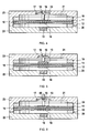
- FIG. 2 shows a detail of a converter according to the invention.
- the dielectric elastomer layer 10 is fixed together with electrodes.
- the upper electrode 11 is arranged centrally on the layer 10.
- the upper magnet 13 together with the indicator pin 16 has the upper ring 19 and the lower ring 20 each have recesses which release the elastomer layer 10 and the electrode lying thereon. In this way, contacting the electrodes of the fixed elastomer layer 10 can be achieved with little effort.
- magnets 30, 31, 32, 33 are mounted in recesses stationary. Due to the perspective view of the oblique view is not visible visible located on the bottom of the lower ring 20 also magnets. These are vertically centered over the respective magnets 30, 31, 32, 33 are arranged. The magnets of the two rings 19, 20 exert an attraction to their counterpart of the other ring. This results in the force that holds the two rings 19, 20 on each other and thus fixes the dielectric layer 10.
- the side facing the layer 10 of the magnet 30 could be, for example, a magnetic north pole, the corresponding side of the adjacent magnet 31 a magnetic south pole, and so on.
- the two rings 19, 20 have a recess, from which the layer 10 and the electrodes emerge.
- FIG. 3 shows an exploded view of a converter according to the invention.
- the components and reference numerals have already been explained above.
- the lower housing cover 22 and the upper housing cover 23 are connected together by screws and nuts. Additional pressure can be exerted on the rings 19, 20 via this housing cover so that the dielectric elastomer layer 10 is even more firmly fixed. Further, not provided with reference numerals recesses in the lower lid 22 provide space for cable for contacting the electrodes on the layer 10.
- FIG. 4 shown inventive converter corresponds in many parts to the converter FIG. 1 , The difference is that the upper, first magnet 13 is made wider and flatter than its counterpart in the converter FIG. 1 , Also, the lower, second magnet 14 is made narrower and flatter. By this construction, the mass moved during the deflection of the layer 10 can be reduced. At the same time, the arrangement comprises comprehensive first Magnets 13 and second magnet 14 still has a larger effective area than the third magnet 15, so that the system is stabilized against tilting moments.
- FIG. 5 shows a way to reduce or avoid unwanted friction in the deflection of the layer 10 and the associated magnets 13, 14.
- the converter according to the invention shown here corresponds in many parts to the converter FIG. 1 , One difference is that the edge of the intended for receiving the first magnet 13 recess 17 is rounded. This results in an upward movement of the magnet 13 only to a small contact between the edge of the magnet 13 and the edge of the recess 17th
- the thickness of the magnet has been adjusted so that upon deflection of the layer 10, the desired amount of contact is achieved.
- Another advantage is that the rounding of the edge of the recess 17 and a guide of the magnet 13 is achieved in such a way that a lateral tilting or canting can be compensated again in the horizontal.
- FIG. 6 A possible use of a converter according to the invention for the control of fluids is in FIG. 6 shown.
- the converter shown here largely corresponds to the converter FIG. 1 ,
- One difference is that in the indicator pin 16, a bore 60 is provided through which fluids can flow.
- a valve is obtained which, depending on the deflection of the dielectric elastomer layer 10 and the display pin 16 coupled thereto, allows fluids to flow through bore 16 or block the flow.
- the position of the bore on the indicator pin 16 is selected so that in the rest position of the layer 10, when not applied electric field, the flow path is closed. This can serve as a safety device if the fluid flow is to be interrupted in the event of a power failure.
- FIG. 7 ac show a further development of a ring for fixing the elastomer layer.
- the in FIG. 7a shown ring 70 is a plastic ring and is used for electrical insulation.
- a bore 71 is attached in this ring 70.
- a circumferential projection 72 is provided, which serves as an abutment for receiving an inner ring.
- This inner ring 73 is in FIG. 7b shown. This is a permanent magnet with an electrically conductive surface.
- the inner ring 73 also has a bore 74.
- FIG. 7c shows how the inner ring 73 is inserted into the plastic ring 70.
- the holes 71, 74 are superimposed so that, for example, electrical lines can be passed through the ring assembly.
- the ring assembly shown here may, for example, one or both of the rings 19, 20 in the in FIG. 2 replaced component shown.
- the accessible part of the inner ring 73 can then contact an electrode.
Priority Applications (3)
| Application Number | Priority Date | Filing Date | Title |
|---|---|---|---|
| EP09013987A EP2320488A1 (fr) | 2009-11-07 | 2009-11-07 | Convertisseur électromécanique avec un élastomère diélectrique |
| PCT/EP2010/066765 WO2011054886A1 (fr) | 2009-11-07 | 2010-11-03 | Convertisseur électromécanique avec élastomère diélectrique |
| TW099138042A TW201145770A (en) | 2009-11-07 | 2010-11-05 | Electromechanical transducer with dielectric elastomer |
Applications Claiming Priority (1)
| Application Number | Priority Date | Filing Date | Title |
|---|---|---|---|
| EP09013987A EP2320488A1 (fr) | 2009-11-07 | 2009-11-07 | Convertisseur électromécanique avec un élastomère diélectrique |
Publications (1)
| Publication Number | Publication Date |
|---|---|
| EP2320488A1 true EP2320488A1 (fr) | 2011-05-11 |
Family
ID=42061061
Family Applications (1)
| Application Number | Title | Priority Date | Filing Date |
|---|---|---|---|
| EP09013987A Withdrawn EP2320488A1 (fr) | 2009-11-07 | 2009-11-07 | Convertisseur électromécanique avec un élastomère diélectrique |
Country Status (3)
| Country | Link |
|---|---|
| EP (1) | EP2320488A1 (fr) |
| TW (1) | TW201145770A (fr) |
| WO (1) | WO2011054886A1 (fr) |
Cited By (1)
| Publication number | Priority date | Publication date | Assignee | Title |
|---|---|---|---|---|
| CN111706633A (zh) * | 2020-06-29 | 2020-09-25 | 郑州轻工业大学 | 电磁力诱导绝缘弹性体电制动器面外制动的装置及方法 |
Families Citing this family (7)
| Publication number | Priority date | Publication date | Assignee | Title |
|---|---|---|---|---|
| TWI593943B (zh) | 2015-10-19 | 2017-08-01 | 國立清華大學 | 可調變的感測元件 |
| TWI599764B (zh) | 2015-10-19 | 2017-09-21 | 國立清華大學 | 多階感測元件 |
| WO2017158485A1 (fr) * | 2016-03-14 | 2017-09-21 | Huan Qi | Actionneur électroactif amélioré utilisant des techniques de chargement non linéaires |
| US11213133B2 (en) * | 2017-11-28 | 2022-01-04 | Seiki Chiba | Dielectric elastomer drive sensor system and sheet |
| WO2020149052A1 (fr) * | 2019-01-15 | 2020-07-23 | 豊田合成株式会社 | Dispositif de présentation tactile, procédé de présentation tactile et actionneur |
| JPWO2020262129A1 (fr) | 2019-06-24 | 2020-12-30 | ||
| CN113644801B (zh) * | 2021-06-25 | 2022-07-12 | 浙江大学 | 基于介电弹性体的水下液压系统振动能量采集装置及方法 |
Citations (5)
| Publication number | Priority date | Publication date | Assignee | Title |
|---|---|---|---|---|
| US7320457B2 (en) * | 1997-02-07 | 2008-01-22 | Sri International | Electroactive polymer devices for controlling fluid flow |
| WO2008083325A1 (fr) | 2006-12-29 | 2008-07-10 | Artificial Muscle, Inc. | Transducteurs polymères électroactifs sollicités pour une sortie optimale |
| US20090001855A1 (en) * | 2007-06-29 | 2009-01-01 | Artificial Muscle, Inc. | Electroactive polymer transducers for sensory feedback applications |
| WO2009095170A2 (fr) * | 2008-01-30 | 2009-08-06 | Eads Deutschland Gmbh | Micro-actionneur électromagnétique à membrane |
| US20090250021A1 (en) * | 2007-10-02 | 2009-10-08 | Artificial Muscle, Inc. | Fluid control systems employing compliant electroactive materials |
-
2009
- 2009-11-07 EP EP09013987A patent/EP2320488A1/fr not_active Withdrawn
-
2010
- 2010-11-03 WO PCT/EP2010/066765 patent/WO2011054886A1/fr active Application Filing
- 2010-11-05 TW TW099138042A patent/TW201145770A/zh unknown
Patent Citations (5)
| Publication number | Priority date | Publication date | Assignee | Title |
|---|---|---|---|---|
| US7320457B2 (en) * | 1997-02-07 | 2008-01-22 | Sri International | Electroactive polymer devices for controlling fluid flow |
| WO2008083325A1 (fr) | 2006-12-29 | 2008-07-10 | Artificial Muscle, Inc. | Transducteurs polymères électroactifs sollicités pour une sortie optimale |
| US20090001855A1 (en) * | 2007-06-29 | 2009-01-01 | Artificial Muscle, Inc. | Electroactive polymer transducers for sensory feedback applications |
| US20090250021A1 (en) * | 2007-10-02 | 2009-10-08 | Artificial Muscle, Inc. | Fluid control systems employing compliant electroactive materials |
| WO2009095170A2 (fr) * | 2008-01-30 | 2009-08-06 | Eads Deutschland Gmbh | Micro-actionneur électromagnétique à membrane |
Cited By (1)
| Publication number | Priority date | Publication date | Assignee | Title |
|---|---|---|---|---|
| CN111706633A (zh) * | 2020-06-29 | 2020-09-25 | 郑州轻工业大学 | 电磁力诱导绝缘弹性体电制动器面外制动的装置及方法 |
Also Published As
| Publication number | Publication date |
|---|---|
| WO2011054886A1 (fr) | 2011-05-12 |
| TW201145770A (en) | 2011-12-16 |
Similar Documents
| Publication | Publication Date | Title |
|---|---|---|
| EP2320488A1 (fr) | Convertisseur électromécanique avec un élastomère diélectrique | |
| DE112017004000B4 (de) | Linearaktuator | |
| DE102008004909B4 (de) | Bedienelement mit verbesserter Kipphaptik | |
| DE102009039433B4 (de) | Drehbare Plattform | |
| DE112018003334T5 (de) | Aktuator | |
| WO2009095170A2 (fr) | Micro-actionneur électromagnétique à membrane | |
| DE102012221107B3 (de) | Bedienvorrichtung für eine Fahrzeugkomponente | |
| EP2924535A2 (fr) | Joystick à retour d'effort intrinsèquement sûr | |
| DE102013114079A1 (de) | Vorrichtungen zur haptischen Rückmeldung | |
| EP3328682A1 (fr) | Dispositif de réglage pneumatique d'un siège dans un moyen de transport | |
| WO2019193006A1 (fr) | Dispositif de production d'une réponse haptique | |
| DE102017120131A1 (de) | Folienwandler sowie Ventil | |
| DE112017005437T5 (de) | Anzeigevorrichtung mit Berührungsfeld Beschreibung | |
| DE102017107366A1 (de) | Bedienvorrichtung mit aktiver haptischer Feedbackerzeugung und Schwingungsdämpfer | |
| EP1839028A1 (fr) | Dispositif d'essai de charge dynamique sur un echantillon | |
| DE102017127745B4 (de) | Vorgespannter Trägheitsantrieb | |
| DE102018218637B3 (de) | Elektroaktive Polymeraktuatoreinrichtung | |
| EP1721082A1 (fr) | Revetement a actionneur polymere integre pour la deformation dudit revetement | |
| EP3924295A1 (fr) | Mems et procédé pour sa fabrication | |
| DE102017130199B4 (de) | Folienwandler, Ventil, Pumpe sowie Verfahren zum Betreiben einer Pumpe | |
| DE102016121425A1 (de) | Bedienelement mit haptisch bewegbarem Touchpad oder Touchscreen und magnetischer Rückstellung | |
| EP1294064A2 (fr) | Contact électrique pour cellules de commutation à isolation gazeuse | |
| DE102014224835B4 (de) | Kopfstütze | |
| DE102018208377A1 (de) | Instrumententafel mit haptischer Rückmeldevorrichtung | |
| WO2006048137A1 (fr) | Dispositif de commutation electrique a elements de deplacement magnetiques |
Legal Events
| Date | Code | Title | Description |
|---|---|---|---|
| PUAI | Public reference made under article 153(3) epc to a published international application that has entered the european phase |
Free format text: ORIGINAL CODE: 0009012 |
|
| AK | Designated contracting states |
Kind code of ref document: A1 Designated state(s): AT BE BG CH CY CZ DE DK EE ES FI FR GB GR HR HU IE IS IT LI LT LU LV MC MK MT NL NO PL PT RO SE SI SK SM TR |
|
| AX | Request for extension of the european patent |
Extension state: AL BA RS |
|
| STAA | Information on the status of an ep patent application or granted ep patent |
Free format text: STATUS: THE APPLICATION HAS BEEN WITHDRAWN |
|
| 18W | Application withdrawn |
Effective date: 20111201 |