EP2319553A1 - Ensemble de tubulure doté d'une porte pour la connexion de flacons - Google Patents
Ensemble de tubulure doté d'une porte pour la connexion de flacons Download PDFInfo
- Publication number
- EP2319553A1 EP2319553A1 EP09175001A EP09175001A EP2319553A1 EP 2319553 A1 EP2319553 A1 EP 2319553A1 EP 09175001 A EP09175001 A EP 09175001A EP 09175001 A EP09175001 A EP 09175001A EP 2319553 A1 EP2319553 A1 EP 2319553A1
- Authority
- EP
- European Patent Office
- Prior art keywords
- vial
- drug
- tubing set
- drip chamber
- air
- Prior art date
- Legal status (The legal status is an assumption and is not a legal conclusion. Google has not performed a legal analysis and makes no representation as to the accuracy of the status listed.)
- Withdrawn
Links
Images


Classifications
-
- A—HUMAN NECESSITIES
- A61—MEDICAL OR VETERINARY SCIENCE; HYGIENE
- A61M—DEVICES FOR INTRODUCING MEDIA INTO, OR ONTO, THE BODY; DEVICES FOR TRANSDUCING BODY MEDIA OR FOR TAKING MEDIA FROM THE BODY; DEVICES FOR PRODUCING OR ENDING SLEEP OR STUPOR
- A61M1/00—Suction or pumping devices for medical purposes; Devices for carrying-off, for treatment of, or for carrying-over, body-liquids; Drainage systems
- A61M1/34—Filtering material out of the blood by passing it through a membrane, i.e. hemofiltration or diafiltration
- A61M1/3413—Diafiltration
-
- A—HUMAN NECESSITIES
- A61—MEDICAL OR VETERINARY SCIENCE; HYGIENE
- A61M—DEVICES FOR INTRODUCING MEDIA INTO, OR ONTO, THE BODY; DEVICES FOR TRANSDUCING BODY MEDIA OR FOR TAKING MEDIA FROM THE BODY; DEVICES FOR PRODUCING OR ENDING SLEEP OR STUPOR
- A61M1/00—Suction or pumping devices for medical purposes; Devices for carrying-off, for treatment of, or for carrying-over, body-liquids; Drainage systems
- A61M1/36—Other treatment of blood in a by-pass of the natural circulatory system, e.g. temperature adaptation, irradiation ; Extra-corporeal blood circuits
- A61M1/3672—Means preventing coagulation
-
- A—HUMAN NECESSITIES
- A61—MEDICAL OR VETERINARY SCIENCE; HYGIENE
- A61J—CONTAINERS SPECIALLY ADAPTED FOR MEDICAL OR PHARMACEUTICAL PURPOSES; DEVICES OR METHODS SPECIALLY ADAPTED FOR BRINGING PHARMACEUTICAL PRODUCTS INTO PARTICULAR PHYSICAL OR ADMINISTERING FORMS; DEVICES FOR ADMINISTERING FOOD OR MEDICINES ORALLY; BABY COMFORTERS; DEVICES FOR RECEIVING SPITTLE
- A61J1/00—Containers specially adapted for medical or pharmaceutical purposes
- A61J1/14—Details; Accessories therefor
- A61J1/20—Arrangements for transferring or mixing fluids, e.g. from vial to syringe
- A61J1/2089—Containers or vials which are to be joined to each other in order to mix their contents
-
- A—HUMAN NECESSITIES
- A61—MEDICAL OR VETERINARY SCIENCE; HYGIENE
- A61M—DEVICES FOR INTRODUCING MEDIA INTO, OR ONTO, THE BODY; DEVICES FOR TRANSDUCING BODY MEDIA OR FOR TAKING MEDIA FROM THE BODY; DEVICES FOR PRODUCING OR ENDING SLEEP OR STUPOR
- A61M1/00—Suction or pumping devices for medical purposes; Devices for carrying-off, for treatment of, or for carrying-over, body-liquids; Drainage systems
- A61M1/36—Other treatment of blood in a by-pass of the natural circulatory system, e.g. temperature adaptation, irradiation ; Extra-corporeal blood circuits
- A61M1/3621—Extra-corporeal blood circuits
- A61M1/3639—Blood pressure control, pressure transducers specially adapted therefor
-
- A—HUMAN NECESSITIES
- A61—MEDICAL OR VETERINARY SCIENCE; HYGIENE
- A61M—DEVICES FOR INTRODUCING MEDIA INTO, OR ONTO, THE BODY; DEVICES FOR TRANSDUCING BODY MEDIA OR FOR TAKING MEDIA FROM THE BODY; DEVICES FOR PRODUCING OR ENDING SLEEP OR STUPOR
- A61M1/00—Suction or pumping devices for medical purposes; Devices for carrying-off, for treatment of, or for carrying-over, body-liquids; Drainage systems
- A61M1/36—Other treatment of blood in a by-pass of the natural circulatory system, e.g. temperature adaptation, irradiation ; Extra-corporeal blood circuits
- A61M1/3621—Extra-corporeal blood circuits
- A61M1/3627—Degassing devices; Buffer reservoirs; Drip chambers; Blood filters
-
- A—HUMAN NECESSITIES
- A61—MEDICAL OR VETERINARY SCIENCE; HYGIENE
- A61M—DEVICES FOR INTRODUCING MEDIA INTO, OR ONTO, THE BODY; DEVICES FOR TRANSDUCING BODY MEDIA OR FOR TAKING MEDIA FROM THE BODY; DEVICES FOR PRODUCING OR ENDING SLEEP OR STUPOR
- A61M39/00—Tubes, tube connectors, tube couplings, valves, access sites or the like, specially adapted for medical use
- A61M39/08—Tubes; Storage means specially adapted therefor
- A61M2039/082—Multi-lumen tubes
-
- A—HUMAN NECESSITIES
- A61—MEDICAL OR VETERINARY SCIENCE; HYGIENE
- A61M—DEVICES FOR INTRODUCING MEDIA INTO, OR ONTO, THE BODY; DEVICES FOR TRANSDUCING BODY MEDIA OR FOR TAKING MEDIA FROM THE BODY; DEVICES FOR PRODUCING OR ENDING SLEEP OR STUPOR
- A61M2205/00—General characteristics of the apparatus
- A61M2205/07—General characteristics of the apparatus having air pumping means
-
- A—HUMAN NECESSITIES
- A61—MEDICAL OR VETERINARY SCIENCE; HYGIENE
- A61M—DEVICES FOR INTRODUCING MEDIA INTO, OR ONTO, THE BODY; DEVICES FOR TRANSDUCING BODY MEDIA OR FOR TAKING MEDIA FROM THE BODY; DEVICES FOR PRODUCING OR ENDING SLEEP OR STUPOR
- A61M2205/00—General characteristics of the apparatus
- A61M2205/33—Controlling, regulating or measuring
- A61M2205/3331—Pressure; Flow
Definitions
- the invention concerns a tubing set for an extracorporeal circuit comprising a gate for the connection of vials containing drugs, in particular a tubing set intended to be used with hemodialysis machines.
- the invention further concerns a method for delivering drugs by means of the tubing set.
- WO 87/07159 discloses a medical fluid administration set which is intended for infusions related to an intravenous therapy; such set is not suitable for use in co-operation with a hemodialysis machine.
- the aim of the present invention is therefore to at least partially solve the drawbacks highlighted in relation to known tubing sets for hemodialysis treatments.
- a task of the present invention is to avoid the double transfer of the substance.
- Another task of the present invention is to make it possible to avoid the use of conventional syringes and the respective needles.
- Another task of the present invention is to allow automated processes for the delivery of any medicament, e.g. to allow slow administering of the substances that require it without needing the active presence of the service staff to do so.
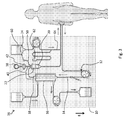
- the reference 10 indicates a hemodialysis machine where a patient's blood is passed through a filter to remove waste products.
- the machine 10 known per se, is provided with a disposable tubing set 12 which comprises:
- the vial gate 24 comprises a delivery lumen 28, suitable for delivering the drug 30 from the vial 26 to the drip chamber 20, and a vent lumen 32, suitable for providing air 34 inside the vial 26 in order to replace the delivered drug.
- the vial gate 24 comprises means 56 for ensuring a safe connection of the vial 26.
- Such means which are not shown in detail in the attached figures, are preferably designed to ensure a tight closure of the extra-corporeal circuit 36 in absence of any vial 26.
- the safe connection means 56 are preferably so arranged that the fluid connection can be opened only when a vial 26 is properly placed on the vial gate 24 and, respectively, the vial 26 can be removed only when the fluid connection is closed.
- the vial gate 24 further comprises means 58 for adjusting the delivery rate of the drug 30.
- the adjusting means 58 are well known in the art. They can comprise for example an adjustable clamp suitable for adjustably obstructing the inner cross section of the delivery lumen 28.
- an extra-corporeal circuit 36 which comprises a tubing set 12 according to the invention and which is associated with a hemodialysis machine 10 known per se.
- the tubing set 12 mainly comprises an out-tube 14 and an in-tube 18.
- a drip chamber 20 is provided in order to remove from the blood any possible gas bubble.
- the drip chamber 20 is considered to be placed along the in-tube 18 which supplies the filtered blood back to the patient.
- the drip chamber 20 is preferably placed along the in-tube 18, thus avoiding the drug 30 to pass through the filter 16, by which it could be easily removed and disposed of together with the waste products.
- the drip chamber 20 provides an air buffer 22 for receiving and stopping any possible gas bubble contained in the blood.
- the air buffer 22 is also connected to a pressure transducer 38 by means of a proper pressure conduit 40.
- Such pressure transducer 38 is intended to constantly provide a measurement of the pressure inside the drip chamber 20.
- the pressure transducer 38 is protected by a transducer protector 42 placed along the conduit 40.
- the transducer protector 42 comprises a hydrophobic semi-permeable membrane which is gas-permeable and liquid-tight. This arrangement, known per se, is intended to avoid any possible blood contamination of the non-disposable portion of the extra-corporeal circuit 36. At the same time it allows the air to freely and safely move along the conduit 40 (dotted arrow on figure 6.a ) so as to instantly provide the pressure value from the drip chamber 20 to the pressure transducer 38.
- the vial gate 24 is designed to take advantage of gravity for the delivery of the drug 30.
- gravity-driven vial gates such type of embodiments will be referred to as gravity-driven vial gates.
- the vial gate is directly connected to the drip chamber 20.
- the vent lumen 32 puts in communication the interior of the vial 26 with the air buffer 22; the delivery lumen 28 puts in communication the interior of the vial 26 with the drip chamber 20.
- the drug 30 is drawn down along the delivery lumen 28 by gravity while air 34 goes up along the vent lumen 32.
- the volume of the delivered drug 30 is thus automatically compensated by an equal volume of air 34, accordingly the pressure inside the vial 26 is promptly equalized to the pressure inside the drip chamber 20.
- the top portion of the delivery lumen 28 is quite different from the top portion of the vent lumen 32.
- the difference between the two top portions, both of which have to be introduced inside the vial 26, are intended to facilitate the drug 30 to flow downward into the delivery lumen 28 rather than into the vent lumen 32.
- air 34 is allowed to flow upward along the vent lumen 32, without any conflict occurring with the downflowing drug 30.
- both the top portions of the delivery lumen 28 and of the vent lumen 32 comprise a hollow needle.
- the top end 46 of the vent lumen 32 can advantageously reach a higher position inside the vial 26 with respect to the top end 48 of the delivery lumen 28.
- the top end 46 of the vent lumen 32 is configured to reach the air bubble contained inside the top of the upside-down vial 26.
- the delivery of the drug 30 involve the air 34 to be sucked directly from the air buffer 22 in the drip chamber 20 into the air bubble in the top of the vial 26.
- other embodiments e.g.
- the top end 46 of the vent lumen 32 is only slightly higher than the top end 48 of the delivery lumen 28, such that both of them are submerged by the liquid drug 30 at the connection of the full vial 26 on the vial gate 24.
- the different height inside the vial 26 involve different pressures for the liquid drug 30 surrounding the top ends 46 and 48 of the two lumina. In particular, the higher pressure acting on the lower portion of the liquid drug 30 facilitates the priming of the delivery lumen 28 instead of the vent lumen 32.
- the delivery of the drug 30 involve the air 34 to be sucked from the air buffer 22 of the drip chamber 20 into the liquid drug 30 so as to form bubbles which rise up to the top of the vial 26 (see also fig. 8 )
- the inner diameter of the top end 48 of the delivery lumen 28 is larger than the inner diameter of the top end 46 of the vent lumen 32. Facing the different diameters of the two top ends 46 and 48, the liquid drug 30, due to its surface tension, enters much more easily the larger one. Thus such arrangement facilitates the priming of the delivery lumen 28 instead of the vent lumen 32.
- the vial gate 24 is preferably located above the drip chamber 20. According to some embodiments (e.g. those shown in figures 4 and 9-11 ) the vial gate 24 is directly mounted on the top wall of the drip chamber 20. According to some other embodiments (e.g. that shown in figures 7 and 8 ) the vial gate 24 is mounted in a remote position with respect to the drip chamber 20 and is connected thereto by means of a double tube 50. Any of such different configurations may be advantageously adopted in order to deal with specific issues deriving from the overall arrangement of the dialysis machine 10.
- the vial gate 24 is designed to take advantage of an air pump 44 for the delivery of the drug 30.
- air-driven vial gates such type of embodiments will be referred to as air-driven vial gates.
- the air-pump 44 is the one already comprised in the machine 10 for controlling the air buffer 22 inside the drip chamber 20.
- the vial gate 24 is placed along the pressure conduit 40, between the drip chamber 20 and the transducer protector 42.
- the vent lumen 32 puts in communication the interior of the vial 26 with the branch 40' of the pressure conduit 40 which comes from the air pump 44 through the transducer protector 42;
- the delivery lumen 28 puts in communication the interior of the vial 26 with the branch 40" of the pressure conduit 40 which goes to the drip chamber 20.
- the air-pump 44 is not the one for controlling the air buffer comprised in the machine 10, but is an additional air pump specifically provided for delivering the drug 30.
- This additional air pump may also be comprised in the machine or may be a separate device.
- the vial gate 24 is placed along a pressure conduit 40, between the drip chamber 20 and the air pump 44.
- the vent lumen 32 puts in communication the interior of the vial 26 with the branch 40' of the pressure conduit 40 which comes from the air pump 44;
- the delivery lumen 28 puts in communication the interior of the vial 26 with the branch 40" of the pressure conduit 40 which goes to the drip chamber 20.
- a pressure transducer 38 and a transducer protector 42 are provided between the air pump 44 and the vial gate 24, a pressure transducer 38 and a transducer protector 42 are provided.
- the air pump 44 when the air pump 44 introduces a volume of air inside the vial 26, the increased pressure pushes an equal volume of drug 30 along the delivery lumen 28, accordingly the pressure inside the vial 26 is promptly equalized to the pressure inside the drip chamber 20.
- the air-driven vial gates 24 there is no need to introduce any difference between the top portion of the delivery lumen 28 and the top portion of the vent lumen 32.
- Such embodiments do not even need, in their proper use configuration, a specific location of the vial gate 24 with respect to the drip chamber 20.
- the vial gate 24 can be either located above the drip chamber 20 or not, since the pressure produced by the air pump 44 can actively push the drug 30 along the delivery lumen 28.
- the vial gate 24 is directly mounted on the pressure conduit 40. According to some other embodiments (not shown) the vial gate 24 is mounted in a remote position with respect to the pressure conduit 40 and is connected thereto by means of a double tube 50. Any of such different configurations may be advantageously adopted in order to deal with specific issues deriving from the overall arrangement of the dialysis machine 10.
- the air-driven vial gates further comprises switch means 54, which are herewith disclosed with specific reference to figures 6.a and 6.b .
- Switch means 54 are intended to allow the pressure conduit 40 to alternatively perform two different functions. The first one is the original function for the pressure conduit 40, i.e. to put in air communication the drip chamber 20 and the pressure transducer 38. The second one is a double function: feeding to the vial 26 the air provided by the air pump 44 (function performed by the branch 40') and delivering the drug 30 from the vial 26 to the drip chamber 20 (function performed by the branch 40").
- the switch means 54 are adapted to alternatively adopt two different configurations.
- the first configuration (measurement configuration) of the switch means 54 ensures the continuity of the pressure conduit 40 and completely cuts off the vial gate 24. In such measurement configuration the switch means 54 allow the pressure conduit 40 to perform its first original function.
- the second configuration (delivery configuration) of the switch means 54 shown in figure 6.b , puts in double communication the vial 26 with the pressure conduit 40 allowing the pressure conduit 40 to perform its second double function.
- the volume of air to be pumped into the vial 26 via the vent lumen 32 is to be determined on the basis of the volume of the drug 30 to be delivered.
- the volume of air 34 will be larger than the volume of drug 30.
- the inner volume of the delivery lumen 28 should be considered in order to completely empty the lumen.
- air compressibility should be considered in some cases, e.g. if the vial 26 is placed lower than the drip chamber 20.
- the pressure transducer 38 can not provide a meaningful value for the pressure inside the drip chamber. Reliability issues arise for the pressure transducer 38 also when the switch means 54 are in the delivery configuration. Such events can be advantageously dealt with by means of specific settings of the machine 10. For example, since most of the hemodialysis machines are electronically controlled, a specific software setting can be used for dealing with the above and other similar events.
- the air pump 44 can be operated in a manner suitable for adjusting the delivery rate of the drug 30, since the volume of drug 30 which is delivered in a time unit depends on the volume of air which is pumped in the vial in the same time unit.
- the delivery rate can be automatically controlled on the base of the pressure measurements provided by the pressure transducer 38.
- the pressure transducer 38 When the pressure transducer 38 is connected to the air buffer 22 of the drip chamber 20 (e.g. when the switch means 54 are in their measurement configuration), the pressure transducer 38 can provide the pressure value inside the air buffer 22.
- the pressure transducer 38 is connected to the vial 26 (e.g.
- the pressure transducer 38 can provide the pressure value inside the vial 26.
- the instant difference between the two pressure values provides the actual force moving the liquid drug 30 along the delivery lumen 28.
- the air-pump 44 is automatically controlled on the base of the pressure difference provided by the pressure transducer 38, so as to adjust the drug delivery rate.
- a second pressure transducer measuring the pressure in the pressure conduit connected to the vent lumen 32 may be present.
- the pressure in the pressure conduit connected to the vent lumen and the pressure in the drip chamber may be measured simultaneously and the current pressure difference may be determined at all times.
- the opening at the top end 48 of the delivery lumen 28 is advantageously placed so as to be, when the vial 26 is properly connected to the vial gate 24, as close as possible to the puncturable membrane 52 of the vial 26.
- An opening of the delivery lumen which is very close to the membrane 52 allows a very effective emptying of the vial 26, i.e. allows a complete delivery of the drug 30.
- the vial gate 24 is intended as a delivery point for several different drugs. Accordingly, when the delivery of a first drug comes to an end, the related first vial 26 can be removed and replaced by a second vial 26 containing a second drug. If incompatibility issues occur between the first and the second drug, one or more of the following expedients can be adopted.
- the delivery lumen 28, intended to successively contain the flows of the two incompatible drugs may be advantageously designed so as to be as short as possible. In such a way, the remainder droplets of the first drug, which will be mixed with the flow of the second drug, are minimized.
- This solution can be obtained for example by mounting the vial gate 24 directly on the top wall of the drip chamber 20 (see figures 4 and 9 to 11 ) or directly on the pressure conduit 40 as close as possible to the drip chamber 20 (see figure 5 ).
- the delivery lumen 28 may advantageously comprise means suitable for minimizing the adhesion of the drug droplets.
- Such means may in turn comprise an inner layer having low adhesion properties.
- a lumen with such an inner layer may be manufactured by co-extrusion, polymer grafting or coating with a low adhesion material known in the art.
- one solution is to have a surface obtained from a very hydrophobic material, for example from Poly-TetraFluoroEthylene (PTFE) or of other similar materials.
- Another solution is to attach a hydrophilic hydrogel by coating or grafting and thereby increasing the fluid flow on the surface by enhancing the wettability. This solution and some related methods for providing a hydrogel coating on a polymer substrate are described for example in patent US 7,572,489 .
- a saline solution may be used for washing the delivery lumen 28 so as to remove the remainder droplets of the first drug before the delivery of the second drug.
- Such saline solution may be for example supplied by means of a simple vial 26. Otherwise the saline solution may be supplied by the substitution liquid circuit which is available on some machines 10.
- most of the recent hemodialysis machines 10 are designed according to the scheme of figure 3 rather than those of figures 1 or 2 .
- Such machines 10 are intended to perform also hemofiltration and/or hemodiafiltration treatments. Such treatments imply the removal of some waste water from the blood and, accordingly, they need also to compensate the removal by means of the addition of saline solution, i.e. the so called the substitution liquid 60.
- hemofiltration machines comprise also a substitution circuit 64.
- the substitution circuit 64 may advantageously comprise a fake vial 62, fed by the substitution liquid 60 flowing in the circuit 64, and suitable for being connected to the vial gate 24 exactly like a common vial 26.
- the delivery of drugs from a lot of vials 26 in quick succession may improperly increase the liquid level inside the drip chamber 20.
- the service staff can operate the pump 44 to supply lacking air in the drip chamber 20 and to restore the correct air buffer 22 and blood level.
- the air pump 44 may also be activated as a precautionary step of the drug delivery method.
- a volume of air equal to the volume of drug 30 in the vial 26 may be introduced in the drip chamber 20 prior to the drug delivery.
- the switch means 54 In order to properly introduce air 34 in the drip chamber 20 the switch means 54 have to be in the measurement configuration ( figure 6.a ). Otherwise, if the switch means 54 were in the delivery configuration ( figure 6.b ), the activation of the air pump 44 would result in the prompt delivery of the drug 30.
- the precautionary air supply avoids any possible improper reduction of the air buffer 22.
- the invention also relates to a method for delivering a drug 30 in a hemodialysis extra-corporeal circuit 36.
- the method comprises the steps of:
- the method further comprises one or more of the following steps:
- the present invention overcomes most of the drawbacks pointed out with respect to the prior art.
- the present invention avoids the double transfer of the drug, from the vial to the syringe first and then from the syringe to the extra-corporeal circuit.
- the present invention avoids the use of some disposable items, i.e. the conventional syringes and the respective needles.
- the present invention allows slow administering of the drugs that require it, without needing the active presence of the service staff to do SO.
Priority Applications (19)
| Application Number | Priority Date | Filing Date | Title |
|---|---|---|---|
| EP09175001A EP2319553A1 (fr) | 2009-11-04 | 2009-11-04 | Ensemble de tubulure doté d'une porte pour la connexion de flacons |
| PL10768940T PL2496282T3 (pl) | 2009-11-04 | 2010-10-25 | Zestaw przewodów rurowych posiadający wejście dla połączenia fiolek |
| EP10768940.8A EP2496282B1 (fr) | 2009-11-04 | 2010-10-25 | Ensemble de tubulure doté d'une porte pour la connexion de flacons |
| US13/505,320 US9839737B2 (en) | 2009-11-04 | 2010-10-25 | Tubing set having a gate for the connection of vials |
| EA201270530A EA023698B1 (ru) | 2009-11-04 | 2010-10-25 | Устройство и способ доставки лекарственных препаратов |
| BR112012010495-0A BR112012010495B1 (pt) | 2009-11-04 | 2010-10-25 | Conjunto de tubos tendo uma porta para a conexão de frascos |
| AU2010314272A AU2010314272B2 (en) | 2009-11-04 | 2010-10-25 | Tubing set having a gate for the connection of vials |
| BR122019022683-0A BR122019022683B1 (pt) | 2009-11-04 | 2010-10-25 | Conjunto de tubos tendo uma porta para a conexão de frascos |
| EP16172219.4A EP3081247B1 (fr) | 2009-11-04 | 2010-10-25 | Ensemble de tubulure doté d'une porte pour la connexion de flacons |
| DK10768940.8T DK2496282T3 (en) | 2009-11-04 | 2010-10-25 | Tubing set with an opening for connection of the tubes |
| PCT/EP2010/066056 WO2011054693A1 (fr) | 2009-11-04 | 2010-10-25 | Ensemble de tubulure comportant une porte pour la connexion de flacons |
| KR1020127014235A KR101700271B1 (ko) | 2009-11-04 | 2010-10-25 | 약병들의 접속을 위한 게이트를 가진 튜빙 세트 |
| CN201080049760.1A CN102711864B (zh) | 2009-11-04 | 2010-10-25 | 具有用于连接药瓶的门的管组 |
| ES10768940.8T ES2597553T3 (es) | 2009-11-04 | 2010-10-25 | Conjunto de tubos que tiene un puerto para la conexión de viales |
| CA2779660A CA2779660C (fr) | 2009-11-04 | 2010-10-25 | Ensemble de tubulure comportant une porte pour la connexion de flacons |
| JP2012537342A JP5864428B2 (ja) | 2009-11-04 | 2010-10-25 | バイアルの接続のためのゲートを有するチューブセット |
| ES16172219T ES2732232T3 (es) | 2009-11-04 | 2010-10-25 | Conjunto de tubos que tiene un puerto para la conexión de viales |
| TW099136931A TWI558425B (zh) | 2009-11-04 | 2010-10-28 | 具有連接藥瓶之閘口的迴路管以及血液透析系統 |
| ARP100104052A AR079276A1 (es) | 2009-11-04 | 2010-11-02 | Juego de tubos que posee una compuerta para la conexion de frascos |
Applications Claiming Priority (1)
| Application Number | Priority Date | Filing Date | Title |
|---|---|---|---|
| EP09175001A EP2319553A1 (fr) | 2009-11-04 | 2009-11-04 | Ensemble de tubulure doté d'une porte pour la connexion de flacons |
Publications (1)
| Publication Number | Publication Date |
|---|---|
| EP2319553A1 true EP2319553A1 (fr) | 2011-05-11 |
Family
ID=41718354
Family Applications (3)
| Application Number | Title | Priority Date | Filing Date |
|---|---|---|---|
| EP09175001A Withdrawn EP2319553A1 (fr) | 2009-11-04 | 2009-11-04 | Ensemble de tubulure doté d'une porte pour la connexion de flacons |
| EP16172219.4A Not-in-force EP3081247B1 (fr) | 2009-11-04 | 2010-10-25 | Ensemble de tubulure doté d'une porte pour la connexion de flacons |
| EP10768940.8A Active EP2496282B1 (fr) | 2009-11-04 | 2010-10-25 | Ensemble de tubulure doté d'une porte pour la connexion de flacons |
Family Applications After (2)
| Application Number | Title | Priority Date | Filing Date |
|---|---|---|---|
| EP16172219.4A Not-in-force EP3081247B1 (fr) | 2009-11-04 | 2010-10-25 | Ensemble de tubulure doté d'une porte pour la connexion de flacons |
| EP10768940.8A Active EP2496282B1 (fr) | 2009-11-04 | 2010-10-25 | Ensemble de tubulure doté d'une porte pour la connexion de flacons |
Country Status (15)
| Country | Link |
|---|---|
| US (1) | US9839737B2 (fr) |
| EP (3) | EP2319553A1 (fr) |
| JP (1) | JP5864428B2 (fr) |
| KR (1) | KR101700271B1 (fr) |
| CN (1) | CN102711864B (fr) |
| AR (1) | AR079276A1 (fr) |
| AU (1) | AU2010314272B2 (fr) |
| BR (2) | BR122019022683B1 (fr) |
| CA (1) | CA2779660C (fr) |
| DK (1) | DK2496282T3 (fr) |
| EA (1) | EA023698B1 (fr) |
| ES (2) | ES2732232T3 (fr) |
| PL (1) | PL2496282T3 (fr) |
| TW (1) | TWI558425B (fr) |
| WO (1) | WO2011054693A1 (fr) |
Cited By (5)
| Publication number | Priority date | Publication date | Assignee | Title |
|---|---|---|---|---|
| DE102014013892A1 (de) | 2014-09-18 | 2016-03-24 | Fresenius Medical Care Deutschland Gmbh | Vorrichtung zum Anschluss einer Durchstechflasche an einen Behälter oder an eine Fluidleitung und Überführung des Inhaltes einer Durchstechflasche in einen Behälter oder in eine Fluidleitung, sowie Verfahren hierzu und Verwendung einer solchen Vorichtung |
| US9498615B2 (en) | 2010-01-29 | 2016-11-22 | Fresenius Medical Care Deutschland Gmbh | Insert for the infusion of drugs |
| US9539387B2 (en) | 2010-12-10 | 2017-01-10 | Fresenius Medical Care Deutschalnd Gmbh | Insert and vial for the infusion of liquids |
| US9623175B2 (en) | 2010-05-14 | 2017-04-18 | Presenius Medical Care Deutschland Gmbh | Tubing set having a gate for the connection of vials |
| WO2017097774A1 (fr) * | 2015-12-08 | 2017-06-15 | Fresenius Medical Care Deutschland Gmbh | Procédé pour la détermination d'un paramètre d'un médicament liquide pendant un traitement extracorporel du sang et dispositif de traitement du sang |
Families Citing this family (11)
| Publication number | Priority date | Publication date | Assignee | Title |
|---|---|---|---|---|
| BR122012017389B8 (pt) | 2009-07-01 | 2021-06-22 | Fresenius Medical Care Holdings Inc | dispositivo para administração de fármacos |
| WO2012106174A1 (fr) | 2011-01-31 | 2012-08-09 | Fresenius Medical Care Holdings, Inc. | Prévention de la suradministration de médicament |
| WO2012108984A1 (fr) | 2011-02-08 | 2012-08-16 | Fresenius Medical Care Holdings, Inc. | Capteurs magnétiques et systèmes et procédés associés |
| CN103998072B (zh) | 2011-09-19 | 2018-02-06 | 弗雷森纽斯医疗护理控股有限公司 | 透析患者的干重量估计 |
| EP2599518A1 (fr) | 2011-11-30 | 2013-06-05 | Fresenius Medical Care Deutschland GmbH | Connecteur avec tube à double lumière |
| US9144646B2 (en) | 2012-04-25 | 2015-09-29 | Fresenius Medical Care Holdings, Inc. | Vial spiking devices and related assemblies and methods |
| EP2662101B2 (fr) * | 2012-05-09 | 2018-05-30 | D_MED Consulting AG | Procédé de préremplissage d'un appareil d'hémodialyse |
| EP2708219A1 (fr) * | 2012-09-12 | 2014-03-19 | PARI Pharma GmbH | Élément d'ouverture pour ouvrir une ampoule dans un dispositif de génération d'aérosol et dispositif de génération d'aérosol comprenant l'élément d'ouverture |
| JP2015000113A (ja) * | 2013-06-13 | 2015-01-05 | サンデン商事株式会社 | 環状多糖類を用いた血中の脂質除去システム |
| EP3744368A1 (fr) | 2018-10-05 | 2020-12-02 | Sorrel Medical Ltd. | Déclenchement de séquence |
| CN113018550A (zh) * | 2021-03-11 | 2021-06-25 | 深圳市人民医院 | 一种便携式心衰脱水装置 |
Citations (7)
| Publication number | Priority date | Publication date | Assignee | Title |
|---|---|---|---|---|
| US4396016A (en) * | 1977-09-07 | 1983-08-02 | Becker Karl E | Intravenous solution flow regulator |
| EP0192588A1 (fr) * | 1985-02-01 | 1986-08-27 | Clinique Universitaire Gasthuisberg | Rein artificiel et produit à mettre en oeuvre dans un traitement extracorporel du sang |
| WO1987007159A1 (fr) | 1986-05-29 | 1987-12-03 | Baxter Travenol Laboratories, Inc. | Systeme d'administration passive d'un medicament |
| EP0568265A2 (fr) * | 1992-04-30 | 1993-11-03 | David S. Utterberg | Chambre d'écoulement moulée par soufflage pour hémodialyse |
| EP0904789A2 (fr) * | 1997-09-22 | 1999-03-31 | Gambro Ab | Méthode et dispositif de surveillance d'une pompe de perfusion |
| US20020115981A1 (en) * | 1995-05-02 | 2002-08-22 | Carmel Pharma Ab | Apparatus for administrating toxic fluid |
| US7572489B2 (en) | 2002-08-22 | 2009-08-11 | Fresenius Medical Care Deutschland Gmbh | Method for immobilizing hydrogel-forming polymers on polymer substrate surfaces |
Family Cites Families (10)
| Publication number | Priority date | Publication date | Assignee | Title |
|---|---|---|---|---|
| US5897526A (en) | 1996-06-26 | 1999-04-27 | Vaillancourt; Vincent L. | Closed system medication administering system |
| JPH11227845A (ja) | 1998-02-19 | 1999-08-24 | Material Eng Tech Lab Inc | 混注口を有する容器 |
| JP2002248166A (ja) * | 2001-02-22 | 2002-09-03 | Nikkiso Co Ltd | 薬液注入具 |
| JP4331675B2 (ja) * | 2002-05-16 | 2009-09-16 | スコット・ラボラトリーズ・インコーポレイテッド | 薬剤容器挿入機構および方法 |
| US8282608B2 (en) * | 2004-01-29 | 2012-10-09 | Becton, Dickinson And Company | Self priming intravenous delivery system |
| DE102005001779B4 (de) * | 2005-01-14 | 2009-12-17 | Fresenius Medical Care Deutschland Gmbh | Disposable zum Betreiben einer Blutbehandlungsvorrichtung im Einnadel- oder Zweinadel-Betrieb |
| CN101269246B (zh) * | 2008-05-05 | 2011-10-12 | 重庆山外山科技有限公司 | 一种带置换液净化器的连续血液净化设备 |
| WO2010099816A1 (fr) | 2009-03-02 | 2010-09-10 | Vifor (International) Ag | Machine de dialyse, collecteur pour machine de dialyse et procédé associé |
| IT1394343B1 (it) | 2009-06-15 | 2012-06-06 | Borla Ind | Dispositivo per la somministrazione controllata di un liquido ad una linea di flusso medicale |
| BR122012017389B8 (pt) * | 2009-07-01 | 2021-06-22 | Fresenius Medical Care Holdings Inc | dispositivo para administração de fármacos |
-
2009
- 2009-11-04 EP EP09175001A patent/EP2319553A1/fr not_active Withdrawn
-
2010
- 2010-10-25 PL PL10768940T patent/PL2496282T3/pl unknown
- 2010-10-25 EP EP16172219.4A patent/EP3081247B1/fr not_active Not-in-force
- 2010-10-25 WO PCT/EP2010/066056 patent/WO2011054693A1/fr active Application Filing
- 2010-10-25 AU AU2010314272A patent/AU2010314272B2/en not_active Ceased
- 2010-10-25 DK DK10768940.8T patent/DK2496282T3/en active
- 2010-10-25 CA CA2779660A patent/CA2779660C/fr not_active Expired - Fee Related
- 2010-10-25 ES ES16172219T patent/ES2732232T3/es active Active
- 2010-10-25 BR BR122019022683-0A patent/BR122019022683B1/pt not_active IP Right Cessation
- 2010-10-25 US US13/505,320 patent/US9839737B2/en active Active
- 2010-10-25 EA EA201270530A patent/EA023698B1/ru not_active IP Right Cessation
- 2010-10-25 EP EP10768940.8A patent/EP2496282B1/fr active Active
- 2010-10-25 ES ES10768940.8T patent/ES2597553T3/es active Active
- 2010-10-25 KR KR1020127014235A patent/KR101700271B1/ko active IP Right Grant
- 2010-10-25 CN CN201080049760.1A patent/CN102711864B/zh not_active Expired - Fee Related
- 2010-10-25 BR BR112012010495-0A patent/BR112012010495B1/pt not_active IP Right Cessation
- 2010-10-25 JP JP2012537342A patent/JP5864428B2/ja not_active Expired - Fee Related
- 2010-10-28 TW TW099136931A patent/TWI558425B/zh not_active IP Right Cessation
- 2010-11-02 AR ARP100104052A patent/AR079276A1/es active IP Right Grant
Patent Citations (7)
| Publication number | Priority date | Publication date | Assignee | Title |
|---|---|---|---|---|
| US4396016A (en) * | 1977-09-07 | 1983-08-02 | Becker Karl E | Intravenous solution flow regulator |
| EP0192588A1 (fr) * | 1985-02-01 | 1986-08-27 | Clinique Universitaire Gasthuisberg | Rein artificiel et produit à mettre en oeuvre dans un traitement extracorporel du sang |
| WO1987007159A1 (fr) | 1986-05-29 | 1987-12-03 | Baxter Travenol Laboratories, Inc. | Systeme d'administration passive d'un medicament |
| EP0568265A2 (fr) * | 1992-04-30 | 1993-11-03 | David S. Utterberg | Chambre d'écoulement moulée par soufflage pour hémodialyse |
| US20020115981A1 (en) * | 1995-05-02 | 2002-08-22 | Carmel Pharma Ab | Apparatus for administrating toxic fluid |
| EP0904789A2 (fr) * | 1997-09-22 | 1999-03-31 | Gambro Ab | Méthode et dispositif de surveillance d'une pompe de perfusion |
| US7572489B2 (en) | 2002-08-22 | 2009-08-11 | Fresenius Medical Care Deutschland Gmbh | Method for immobilizing hydrogel-forming polymers on polymer substrate surfaces |
Cited By (6)
| Publication number | Priority date | Publication date | Assignee | Title |
|---|---|---|---|---|
| US9498615B2 (en) | 2010-01-29 | 2016-11-22 | Fresenius Medical Care Deutschland Gmbh | Insert for the infusion of drugs |
| US9623175B2 (en) | 2010-05-14 | 2017-04-18 | Presenius Medical Care Deutschland Gmbh | Tubing set having a gate for the connection of vials |
| US9539387B2 (en) | 2010-12-10 | 2017-01-10 | Fresenius Medical Care Deutschalnd Gmbh | Insert and vial for the infusion of liquids |
| DE102014013892A1 (de) | 2014-09-18 | 2016-03-24 | Fresenius Medical Care Deutschland Gmbh | Vorrichtung zum Anschluss einer Durchstechflasche an einen Behälter oder an eine Fluidleitung und Überführung des Inhaltes einer Durchstechflasche in einen Behälter oder in eine Fluidleitung, sowie Verfahren hierzu und Verwendung einer solchen Vorichtung |
| US10441711B2 (en) | 2014-09-18 | 2019-10-15 | Fresenius Medical Care Deutschland Gmbh | Device for connecting a vial to a container or to a fluid line and transferring the contents of a vial to a container or a fluid line as well as a method for doing so and use of such a device |
| WO2017097774A1 (fr) * | 2015-12-08 | 2017-06-15 | Fresenius Medical Care Deutschland Gmbh | Procédé pour la détermination d'un paramètre d'un médicament liquide pendant un traitement extracorporel du sang et dispositif de traitement du sang |
Also Published As
| Publication number | Publication date |
|---|---|
| BR112012010495B1 (pt) | 2020-09-24 |
| DK2496282T3 (en) | 2016-10-03 |
| TW201124179A (en) | 2011-07-16 |
| CA2779660C (fr) | 2018-05-01 |
| EA201270530A1 (ru) | 2012-12-28 |
| PL2496282T3 (pl) | 2017-01-31 |
| BR122019022683B1 (pt) | 2020-07-14 |
| JP2013509924A (ja) | 2013-03-21 |
| EP2496282B1 (fr) | 2016-07-13 |
| KR20120112442A (ko) | 2012-10-11 |
| US20120271274A1 (en) | 2012-10-25 |
| AU2010314272B2 (en) | 2015-11-12 |
| BR112012010495A2 (pt) | 2016-03-15 |
| WO2011054693A1 (fr) | 2011-05-12 |
| AU2010314272A1 (en) | 2012-05-24 |
| US9839737B2 (en) | 2017-12-12 |
| BR112012010495A8 (pt) | 2020-08-18 |
| EP2496282A1 (fr) | 2012-09-12 |
| CA2779660A1 (fr) | 2011-05-12 |
| JP5864428B2 (ja) | 2016-02-17 |
| KR101700271B1 (ko) | 2017-01-26 |
| EA023698B1 (ru) | 2016-07-29 |
| CN102711864B (zh) | 2016-04-27 |
| ES2732232T3 (es) | 2019-11-21 |
| ES2597553T3 (es) | 2017-01-19 |
| TWI558425B (zh) | 2016-11-21 |
| CN102711864A (zh) | 2012-10-03 |
| EP3081247A1 (fr) | 2016-10-19 |
| AR079276A1 (es) | 2012-01-18 |
| EP3081247B1 (fr) | 2019-03-27 |
Similar Documents
| Publication | Publication Date | Title |
|---|---|---|
| EP3081247B1 (fr) | Ensemble de tubulure doté d'une porte pour la connexion de flacons | |
| US9623175B2 (en) | Tubing set having a gate for the connection of vials | |
| US20180110914A1 (en) | Blood purification device and priming method | |
| EP2305204A1 (fr) | Ensemble de tubage doté d'un insert pour la perfusion de médicaments | |
| EP4005613B1 (fr) | Préparation d'un appareil de traitement extracorporel du sang |
Legal Events
| Date | Code | Title | Description |
|---|---|---|---|
| PUAI | Public reference made under article 153(3) epc to a published international application that has entered the european phase |
Free format text: ORIGINAL CODE: 0009012 |
|
| AK | Designated contracting states |
Kind code of ref document: A1 Designated state(s): AT BE BG CH CY CZ DE DK EE ES FI FR GB GR HR HU IE IS IT LI LT LU LV MC MK MT NL NO PL PT RO SE SI SK SM TR |
|
| AX | Request for extension of the european patent |
Extension state: AL BA RS |
|
| STAA | Information on the status of an ep patent application or granted ep patent |
Free format text: STATUS: THE APPLICATION IS DEEMED TO BE WITHDRAWN |
|
| 18D | Application deemed to be withdrawn |
Effective date: 20111112 |