EP2318219B1 - Bande de roulement de pneu a sculpture directionnelle - Google Patents
Bande de roulement de pneu a sculpture directionnelle Download PDFInfo
- Publication number
- EP2318219B1 EP2318219B1 EP09809306A EP09809306A EP2318219B1 EP 2318219 B1 EP2318219 B1 EP 2318219B1 EP 09809306 A EP09809306 A EP 09809306A EP 09809306 A EP09809306 A EP 09809306A EP 2318219 B1 EP2318219 B1 EP 2318219B1
- Authority
- EP
- European Patent Office
- Prior art keywords
- tread
- grooves
- additional
- main
- groove
- Prior art date
- Legal status (The legal status is an assumption and is not a legal conclusion. Google has not performed a legal analysis and makes no representation as to the accuracy of the status listed.)
- Not-in-force
Links
- 210000005069 ears Anatomy 0.000 claims 4
- 230000001133 acceleration Effects 0.000 description 7
- 230000000694 effects Effects 0.000 description 3
- 238000005096 rolling process Methods 0.000 description 2
- XLYOFNOQVPJJNP-UHFFFAOYSA-N water Substances O XLYOFNOQVPJJNP-UHFFFAOYSA-N 0.000 description 2
- 239000011324 bead Substances 0.000 description 1
- 230000015556 catabolic process Effects 0.000 description 1
- 238000006243 chemical reaction Methods 0.000 description 1
- 238000006731 degradation reaction Methods 0.000 description 1
- 230000005484 gravity Effects 0.000 description 1
- 238000000265 homogenisation Methods 0.000 description 1
- 230000007246 mechanism Effects 0.000 description 1
- 238000012986 modification Methods 0.000 description 1
- 230000004048 modification Effects 0.000 description 1
- 230000002035 prolonged effect Effects 0.000 description 1
- 230000002787 reinforcement Effects 0.000 description 1
- 230000000087 stabilizing effect Effects 0.000 description 1
Images


Classifications
-
- B—PERFORMING OPERATIONS; TRANSPORTING
- B60—VEHICLES IN GENERAL
- B60C—VEHICLE TYRES; TYRE INFLATION; TYRE CHANGING; CONNECTING VALVES TO INFLATABLE ELASTIC BODIES IN GENERAL; DEVICES OR ARRANGEMENTS RELATED TO TYRES
- B60C11/00—Tyre tread bands; Tread patterns; Anti-skid inserts
- B60C11/03—Tread patterns
- B60C11/0302—Tread patterns directional pattern, i.e. with main rolling direction
-
- B—PERFORMING OPERATIONS; TRANSPORTING
- B60—VEHICLES IN GENERAL
- B60C—VEHICLE TYRES; TYRE INFLATION; TYRE CHANGING; CONNECTING VALVES TO INFLATABLE ELASTIC BODIES IN GENERAL; DEVICES OR ARRANGEMENTS RELATED TO TYRES
- B60C11/00—Tyre tread bands; Tread patterns; Anti-skid inserts
- B60C11/03—Tread patterns
- B60C2011/0337—Tread patterns characterised by particular design features of the pattern
- B60C2011/0339—Grooves
- B60C2011/0374—Slant grooves, i.e. having an angle of about 5 to 35 degrees to the equatorial plane
-
- B—PERFORMING OPERATIONS; TRANSPORTING
- B60—VEHICLES IN GENERAL
- B60C—VEHICLE TYRES; TYRE INFLATION; TYRE CHANGING; CONNECTING VALVES TO INFLATABLE ELASTIC BODIES IN GENERAL; DEVICES OR ARRANGEMENTS RELATED TO TYRES
- B60C11/00—Tyre tread bands; Tread patterns; Anti-skid inserts
- B60C11/03—Tread patterns
- B60C2011/0337—Tread patterns characterised by particular design features of the pattern
- B60C2011/0386—Continuous ribs
- B60C2011/0388—Continuous ribs provided at the equatorial plane
Definitions
- the present invention relates to tires for passenger vehicles and more particularly the treads which are provided with said tires, and even more particularly, tires intended to be mounted on high performance vehicles.
- a directional tire comprises a tread having a directional tread such that, when the tire is rotated in the preferred direction, this tire provides better ground adhesion properties than those offered when rotating in the tread. other way.
- carving a tread is meant a plurality of cutouts made in said tread in a suitable pattern, said cutouts having equally suitable widths and depths. Cutouts means either grooves or incisions, the latter (incisions) being distinguished from the first by widths (distance between the facing faces) generally less than 2 mm and even more preferably less than 1 mm).
- a directional tread pattern has main grooves which are arranged to form a series of V-grooves all pointing in the same direction around the tread of the tire.
- the V-shaped grooves point in the direction of travel, so that the middle part (near the median plane of the tire) of each groove V-shaped is the first on the footprint of the tire on the ground.
- the transverse thrust curve as a function of the drift angle of such a tire has a characteristic appearance showing an increase in said transverse thrust to a maximum followed by a significant reduction in transverse thrust for strong drifts (an example of such a curve is shown with the curve C0 on the figure 2 of this document).
- EP0721853 shows a variant of such a sculpture according to which a plurality of additional grooves have been introduced. Some of these additional grooves are formed to connect in pairs the main grooves located on the same side of the tread with respect to the median plane. Other additional grooves are formed to connect in pairs the main grooves located on either side of the median plane. By groove connected to another groove, it should be understood that an additional groove opens at its ends in main grooves.
- additional grooves are here oriented so as to be substantially perpendicular to the main grooves they connect.
- a first additional groove is formed between the axially inner end of a main groove and a second main groove so as to be substantially perpendicular to the second main groove.
- This first additional groove forms with the circumferential direction an angle close to 45 degrees.
- a second additional groove is formed axially outside this first additional groove.
- the main grooves and the first additional grooves delimit a plurality of discontinuous elements in the circumferential direction, some of whose edges are subjected to high overpressures during the steering maneuvers (that is to say in particular under strong transverse accelerations).
- An object of the invention is to propose a sculpture for a tire tread fitted to a passenger vehicle which does not have the drawbacks mentioned above and in particular does not show a significant drop in the drifting thrust with high transverse stresses (in particular turn).
- the subject of the invention is a tread for a tire, as defined in claims 1 and 5, provided with a tread comprising a plurality of main grooves formed on each half of the tread of the tread and other median plane, each of these main grooves of average width L opening axially outside the strip and extending axially inside to a distance from the median plane of the strip between 2.5 and 10 % of the width TW of the tread.
- These main grooves form a generally V-shaped pattern giving this tread a preferential rolling direction such that the axially innermost end of each main groove comes into contact with the roadway before the axially end. the most outside of the same main groove.
- each additional groove - i.e., the closest to said plane - is at a distance D1 from the equatorial plane which is greater than the distance from the same plane of the first ends of the grooves. and less than 18% of the width TW of the strip.
- This tread is such that on each main groove opens at least one additional groove and in that the axially innermost end of each additional groove comes into contact with the roadway before the axially most end. the outside of the same additional groove.
- the tread according to the invention therefore comprises a median portion which extends in the circumferential direction and whose axially opposite edges delimit a plurality of spikes which give the tread good performance both on wet and on dry pavement.
- the median portion of the strip located on either side of the median plane and which is delimited by the main grooves and the additional grooves has a transverse shear stress rigidity which is equal or substantially equal (that is, that is to say very little different) from that of a part of the same geometry and devoid of any cut-out (groove, incision) so as to be able to carry out a total transfer of forces from one side of this part to the other side in the axial direction.
- This middle portion is in particular devoid of circumferential groove. Thanks to a tread according to the invention it is possible to obtain a homogeneous operation of said strip and in particular an almost homogeneous distribution of the contact pressures on this median part by avoiding rocking mechanisms of the elements of matter in this middle part. .
- the additional grooves open on the main grooves only at one end, the other end being distant from another main groove by a distance of less than 50% of the average distance between two main grooves measured in the direction of the additional groove (and even more preferably less than 25% of said distance).
- each additional groove opens at its two ends in main grooves on the same half of the tread.
- the presence of the additional grooves according to the invention makes it possible to improve the shape of the tire thrust curves as a function of the drift angle and, consequently, to improve the equilibrium of the vehicle during specific maneuvers under very strong conditions. transverse accelerations.
- the additional grooves have an average width of at least 1.5 mm and at most equal to 4 mm.
- the plurality of the main grooves formed on one half of the tread is shifted circumferentially with respect to the plurality of the main grooves formed on the other half of the tread.
- additional second grooves connect the main grooves in pairs, these second additional grooves being substantially parallel to the first additional grooves and located at a distance from the equatorial plane between 27 and 37% of the width TW of the tread.
- substantially parallel is meant here that the grooves additional on the same side of the strip have between them a zero angular difference or up to 5 degrees.
- the depths of the first and second additional grooves are at least equal to 50% of the depth of the main grooves.
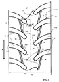
- FIG. 1 shows a partial view in elevation of a tread according to the invention
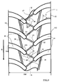
- FIG. 3 shows a partial view in elevation of a tread according to a variant of the invention.
- FIG. 4 shows a partial view in elevation of a tread according to another variant of the invention.
- FIG. 1 shows a partial view in elevation of a part of a tread for a passenger vehicle tire of dimension 195/65 R 15.
- This tire with a radial carcass reinforcement comprises a tread 1 coming into contact of the ground, this band having two lateral edges 12 and 13 spaced from each other by a tread width TW.
- the lateral edges 12 and 13 correspond to the axially outermost points of the tread coming into contact with the roadway, the tire being subjected to nominal pressure and load conditions.
- the tread width TW is defined as being the greatest axial distance of the tire, measured from the footprint of the tire when it is mounted on a given rim and is inflated to a pressure of use under a nominal load; the terms “axial” and “axial” refer to distances taken along or parallel to the axis of rotation of the tire.
- the tread 1 extends beyond its lateral edges 12 and 13 by flanks to beads.
- the tire provided with such a strip has a median circumferential plane (said medial plane X-X ') which is perpendicular to the axis of rotation of the tire and is located midway between the lateral edges 12 and 13 of the strip
- the tread is provided on its radially outer surface with a directional tread formed of main grooves 15 and 16 disposed on each half of the tread (i.e., on each part of the tread strip). rolling on both sides of the median plane X-X ').
- the direction of rotation is indicated by an arrow R in the drawings (this same type of marking may be used on the tire provided with this band to indicate the recommended direction of travel in order to have all the advantages of the invention).
- the main grooves 15 and 16 extend from a medial circumferential portion 17 which is symmetrically disposed on either side of the median plane X-X ', towards a corresponding lateral edge 12 or 13.
- medial circumferential portion of the tread means a portion extending up to at most 28% of the bandwidth TW on each side of the median plane X-X '.
- Each main groove 15 (respectively 16) comprises a first end 151 (respectively 161) and a second end 152 (respectively 162).
- the first ends 151, 161 are located in the middle circumferential portion 17 without being located on the median plane X-X '.
- the axial distance D0 between each of these first ends and the median plane XX ' is equal to 4% of the width TW of the tread (in the example shown, the distances of the first ends of the main grooves both halves of the band are equal).
- the second ends 152, 162 of the main grooves open on the lateral edges 12, 13 of the tread.
- the main grooves 15, 16 have average widths ranging from 5 mm to 8.5 mm and a mean depth equal to 8.5 mm and are arranged to generate generally a V- shaped pattern ; the tip of this V indicating the preferred direction of rotation chosen for this sculpture.
- the geometric shape of each main groove is such that the angle T of the tangent to the ridges formed on the tread by these main grooves with a direction contained in the median plane XX 'increases with the distance between the point of tangency considered and said plane.
- the main grooves 15 of a half of the tread are circumferentially offset from the main grooves 16 of the other half.
- the offset is substantially equal to half the distance between adjacent main grooves on the same tread half.
- the main grooves may not be circumferentially offset from one another.
- this sculpture comprises on each half of the tread and entirely contained in the medial circumferential portion 17, a plurality of additional grooves 20 of width equal to 3 mm and of average orientation A equal in this case to 4 degrees, this orientation being measured with respect to a direction tangent to the circumferential direction.
- Each additional groove 20 comprises a first end 21 and a second end 22, the first end 21 being situated at an axial distance D1 from the median plane XX 'which is here equal to 13% of the width TW of the tread , the second end 22 being located at an axial distance D2 of the median plane XX 'which is equal to 14% of the width TW of the tread.
- each additional groove 20 opens at its two ends in main grooves 15, 16 consecutive of the same half of the tread.
- the angle A of the additional grooves with the circumferential direction is small, that is to say greater than zero degrees and at most equal to 20 degrees; even more preferably, the angle A is at least 4 degrees and at most 15 degrees.
- the figure 2 shows a comparison of the transverse thrust curves Fy recorded with a tire according to the invention (curve Ci) which has just been described and a tire according to the prior art (curve C), the latter being identical to the tire of the invention with the difference that it is provided with additional grooves at an angle of 30 degrees with a tangent to the circumferential direction. It can be seen that for values of drift angle ⁇ greater than the drift giving the maximum thrusts, whereas for the tire of the prior art there is a significant loss of the transverse thrust of the ground on the tire, the tire of the invention records a thrust of almost constant value.
- the variant according to the invention which has just been described with the support of the figure 1 can further be improved by providing the medial circumferential portion 17 with a plurality of oblique grooves 40 connecting the ends 151 of the main grooves 15 of one tread half to the ends 161 of the main grooves 16 on the other tread half as shown with the figure 3 .
- oblique grooves 40 it is essential to provide these oblique grooves 40 with protuberances 41 which prevent the closing of these grooves while transferring in full the transverse forces (parallel to the axis of rotation) on one side of the circumferential central part to the other side of the same part.
- transverse of the medial circumferential portion 17 while benefiting from additional edges useful especially on pavement covered with water.
- the protuberances are arranged on the walls defining the oblique grooves 40 so as to be present regardless of the level of wear of the strip.
- these oblique grooves 40 have widths equal to the widths of the additional grooves 20 and have a depth equal to the depth of the additional grooves.
- the figure 4 shows a variant of sculpture according to the invention for a tread fitted to a tire of the same size as that used for the figure 1 .
- the same references are used to designate the same structural elements.
- the additional grooves 20 open only through a first end 21 in a main groove 15 (or 16).
- the distance H between the second end 22 and the neighboring main groove is less than 50% of the distance D3 measured between two main grooves in the direction of the additional groove and in the variant shown this distance H is equal to 20% of the distance D3.
- the middle portion of the tread is delimited by the main grooves and the additional grooves, the latter being virtually extended to another main groove.
Landscapes
- Engineering & Computer Science (AREA)
- Mechanical Engineering (AREA)
- Tires In General (AREA)
- Toys (AREA)
- Tyre Moulding (AREA)
Applications Claiming Priority (2)
| Application Number | Priority Date | Filing Date | Title |
|---|---|---|---|
| FR0855712A FR2935296B1 (fr) | 2008-08-26 | 2008-08-26 | Bande de roulement de pneu a sculpture directionnelle. |
| PCT/EP2009/060222 WO2010023076A1 (fr) | 2008-08-26 | 2009-08-06 | Bande de roulement de pneu a sculpture directionnelle |
Publications (2)
| Publication Number | Publication Date |
|---|---|
| EP2318219A1 EP2318219A1 (fr) | 2011-05-11 |
| EP2318219B1 true EP2318219B1 (fr) | 2012-04-04 |
Family
ID=40409777
Family Applications (1)
| Application Number | Title | Priority Date | Filing Date |
|---|---|---|---|
| EP09809306A Not-in-force EP2318219B1 (fr) | 2008-08-26 | 2009-08-06 | Bande de roulement de pneu a sculpture directionnelle |
Country Status (9)
Families Citing this family (10)
| Publication number | Priority date | Publication date | Assignee | Title |
|---|---|---|---|---|
| JP5973139B2 (ja) * | 2011-07-26 | 2016-08-23 | 株式会社ブリヂストン | タイヤ |
| FR2998512B1 (fr) * | 2012-11-29 | 2016-07-22 | Michelin & Cie | Bande de roulement de pneumatique a sculpture directionnelle |
| DE102014205515A1 (de) * | 2014-03-25 | 2015-10-01 | Robert Bosch Gmbh | Verfahren und Vorrichtung zum Überprüfen der Reifenmontage an einem Fahrzeug |
| RU2703006C2 (ru) * | 2015-04-03 | 2019-10-15 | Сумитомо Раббер Индастриз, Лтд. | Пневматическая шина |
| CN106827941B (zh) * | 2016-12-20 | 2023-06-16 | 平湖市专博先进技术与转化研究院 | 一种用于童车的车轮 |
| US20200122516A1 (en) * | 2017-06-22 | 2020-04-23 | Bridgestone Corporation | Heavy load tire |
| USD845213S1 (en) | 2017-10-02 | 2019-04-09 | Cooper Tire & Rubber Company | Tire tread |
| JP6648801B1 (ja) * | 2018-10-23 | 2020-02-14 | 横浜ゴム株式会社 | 空気入りタイヤ |
| CN112739554B (zh) * | 2018-11-15 | 2022-12-16 | 米其林集团总公司 | 具有分离胎肩花纹块的带斜花纹条的平均空隙深度卡车轮胎 |
| USD862372S1 (en) * | 2019-05-31 | 2019-10-08 | Omni United (S) Pte Ltd. | Tire tread |
Family Cites Families (24)
| Publication number | Priority date | Publication date | Assignee | Title |
|---|---|---|---|---|
| DE2455130A1 (de) * | 1974-11-21 | 1976-05-26 | Continental Gummi Werke Ag | Luftreifen fuer kraftfahrzeuge |
| US4456046A (en) | 1981-05-11 | 1984-06-26 | Miller Timothy I | High-speed tires |
| DE3470703D1 (en) * | 1984-08-28 | 1988-06-01 | Goodyear Tire & Rubber | A pneumatic tire |
| DE9002986U1 (de) * | 1990-03-12 | 1991-04-04 | Uniroyal Englebert Reifen GmbH, 5100 Aachen | Fahrzeugluftreifen |
| JP2975124B2 (ja) * | 1990-12-19 | 1999-11-10 | 株式会社ブリヂストン | 空気入りタイヤ |
| JP3336512B2 (ja) * | 1994-01-28 | 2002-10-21 | 東洋ゴム工業株式会社 | 空気入りタイヤ |
| JP3467084B2 (ja) * | 1994-08-22 | 2003-11-17 | 株式会社ブリヂストン | 空気入りラジアルタイヤ |
| JPH08104109A (ja) * | 1994-10-06 | 1996-04-23 | Bridgestone Corp | 空気入りタイヤ |
| JPH08104110A (ja) * | 1994-10-06 | 1996-04-23 | Bridgestone Corp | 空気入りタイヤ |
| JP3555777B2 (ja) * | 1994-11-22 | 2004-08-18 | 株式会社ブリヂストン | 方向性傾斜溝を有する高運動性能空気入りタイヤ |
| JPH08188014A (ja) | 1995-01-11 | 1996-07-23 | Bridgestone Corp | 重荷重用空気入りタイヤ |
| JP3542687B2 (ja) * | 1996-06-11 | 2004-07-14 | 株式会社ブリヂストン | 空気入りタイヤ |
| DE19730068C2 (de) * | 1997-07-14 | 2001-12-20 | Continental Ag | Drehsinngebundenes Laufstreifenprofil für Fahrzeugreifen |
| EP0916524A3 (en) * | 1997-11-12 | 2000-11-08 | Bridgestone Corporation | Pneumatic radial tires |
| JP4262813B2 (ja) * | 1998-12-18 | 2009-05-13 | 横浜ゴム株式会社 | スタッドレスタイヤ |
| JP4285617B2 (ja) * | 1999-03-23 | 2009-06-24 | 東洋ゴム工業株式会社 | 空気入りラジアルタイヤ |
| JP4350204B2 (ja) * | 1999-05-14 | 2009-10-21 | 株式会社ブリヂストン | 空気入りタイヤ |
| EP1238827B1 (de) * | 2001-03-06 | 2004-11-03 | Continental Aktiengesellschaft | Reifenprofil |
| JP3999521B2 (ja) * | 2002-01-15 | 2007-10-31 | 株式会社ブリヂストン | 空気入りタイヤ |
| JP3678727B2 (ja) * | 2003-01-07 | 2005-08-03 | 住友ゴム工業株式会社 | 空気入りタイヤ |
| JP4420623B2 (ja) * | 2003-05-28 | 2010-02-24 | 株式会社ブリヂストン | 空気入りタイヤ |
| JP2006137231A (ja) * | 2004-11-10 | 2006-06-01 | Bridgestone Corp | 空気入りタイヤ |
| JP2007055285A (ja) * | 2005-08-22 | 2007-03-08 | Bridgestone Corp | 空気入りタイヤおよび空気入りタイヤの製造方法 |
| JP4486592B2 (ja) * | 2005-12-29 | 2010-06-23 | 住友ゴム工業株式会社 | 重荷重用タイヤ |
-
2008
- 2008-08-26 FR FR0855712A patent/FR2935296B1/fr not_active Expired - Fee Related
-
2009
- 2009-08-06 JP JP2011524298A patent/JP5688018B2/ja not_active Expired - Fee Related
- 2009-08-06 US US13/059,420 patent/US8783313B2/en not_active Expired - Fee Related
- 2009-08-06 CN CN200980133642.6A patent/CN102131656B/zh not_active Expired - Fee Related
- 2009-08-06 EP EP09809306A patent/EP2318219B1/fr not_active Not-in-force
- 2009-08-06 AT AT09809306T patent/ATE552126T1/de active
- 2009-08-06 EA EA201170379A patent/EA018005B1/ru not_active IP Right Cessation
- 2009-08-06 BR BRPI0917162A patent/BRPI0917162A2/pt not_active Application Discontinuation
- 2009-08-06 WO PCT/EP2009/060222 patent/WO2010023076A1/fr active Application Filing
Also Published As
| Publication number | Publication date |
|---|---|
| US8783313B2 (en) | 2014-07-22 |
| CN102131656B (zh) | 2013-09-25 |
| EP2318219A1 (fr) | 2011-05-11 |
| BRPI0917162A2 (pt) | 2015-11-17 |
| EA018005B1 (ru) | 2013-04-30 |
| CN102131656A (zh) | 2011-07-20 |
| WO2010023076A1 (fr) | 2010-03-04 |
| FR2935296A1 (fr) | 2010-03-05 |
| FR2935296B1 (fr) | 2011-07-29 |
| ATE552126T1 (de) | 2012-04-15 |
| JP5688018B2 (ja) | 2015-03-25 |
| US20110168312A1 (en) | 2011-07-14 |
| EA201170379A1 (ru) | 2011-08-30 |
| JP2012500747A (ja) | 2012-01-12 |
Similar Documents
| Publication | Publication Date | Title |
|---|---|---|
| EP2318219B1 (fr) | Bande de roulement de pneu a sculpture directionnelle | |
| EP3102437B1 (fr) | Bande de roulement pour pneu poids lourd | |
| EP2895338B1 (fr) | Bande de roulement et pneu pour poids lourd | |
| EP2834089B1 (fr) | Bande de roulement de pneu pour essieu moteur de poids lourd | |
| EP2925542B1 (fr) | Bande de roulement pour pneumatique neige comportant des incisions et des cavites | |
| EP3102436B1 (fr) | Bande de roulement pour pneu poids lourd | |
| EP2203318B1 (fr) | Bande de roulement de pneu comprenant des plots de gomme pourvus d'encoche. | |
| EP2874829B1 (fr) | Bande de roulement pour pneu d'essieu moteur de poids lourd et pneu | |
| EP3589503B1 (fr) | Bande de roulement de pneu pour vehicule remorque poids lourd | |
| EP2563604B1 (fr) | Bande de roulement de pneu pour vehicule poids lourd de type remorque | |
| EP2661376B1 (fr) | Pneu pour vehicule poids lourd et arrangement de pneus sur essieu moteur et sur essieu directeur | |
| WO2012004285A1 (fr) | Dispositif de protection de bande de roulement | |
| EP3648991B1 (fr) | Pneu dont la bande de roulement comprend des rainures ondulantes | |
| EP2911894B1 (fr) | Bande de roulement évolutive | |
| FR2983780A1 (fr) | Bande de roulement a chanfreins variables | |
| EP2519413B1 (fr) | Bande de roulement de pneu pour vehicule deux roues | |
| WO2014131692A1 (fr) | Bande de roulement améliorée pour pneu de génie civil | |
| EP3898281B1 (fr) | Bande de roulement ayant des cavites cachees prolongees par des ouvertures decalees | |
| EP3383673B1 (fr) | Géométrie de blocs d'une bande de roulement pour pneu |
Legal Events
| Date | Code | Title | Description |
|---|---|---|---|
| PUAI | Public reference made under article 153(3) epc to a published international application that has entered the european phase |
Free format text: ORIGINAL CODE: 0009012 |
|
| 17P | Request for examination filed |
Effective date: 20110328 |
|
| AK | Designated contracting states |
Kind code of ref document: A1 Designated state(s): AT BE BG CH CY CZ DE DK EE ES FI FR GB GR HR HU IE IS IT LI LT LU LV MC MK MT NL NO PL PT RO SE SI SK SM TR |
|
| AX | Request for extension of the european patent |
Extension state: AL BA RS |
|
| GRAP | Despatch of communication of intention to grant a patent |
Free format text: ORIGINAL CODE: EPIDOSNIGR1 |
|
| DAX | Request for extension of the european patent (deleted) | ||
| GRAS | Grant fee paid |
Free format text: ORIGINAL CODE: EPIDOSNIGR3 |
|
| GRAA | (expected) grant |
Free format text: ORIGINAL CODE: 0009210 |
|
| AK | Designated contracting states |
Kind code of ref document: B1 Designated state(s): AT BE BG CH CY CZ DE DK EE ES FI FR GB GR HR HU IE IS IT LI LT LU LV MC MK MT NL NO PL PT RO SE SI SK SM TR |
|
| REG | Reference to a national code |
Ref country code: GB Ref legal event code: FG4D Free format text: NOT ENGLISH |
|
| REG | Reference to a national code |
Ref country code: CH Ref legal event code: EP |
|
| REG | Reference to a national code |
Ref country code: AT Ref legal event code: REF Ref document number: 552126 Country of ref document: AT Kind code of ref document: T Effective date: 20120415 |
|
| REG | Reference to a national code |
Ref country code: IE Ref legal event code: FG4D Free format text: LANGUAGE OF EP DOCUMENT: FRENCH |
|
| REG | Reference to a national code |
Ref country code: DE Ref legal event code: R096 Ref document number: 602009006289 Country of ref document: DE Effective date: 20120531 |
|
| REG | Reference to a national code |
Ref country code: NL Ref legal event code: VDEP Effective date: 20120404 |
|
| REG | Reference to a national code |
Ref country code: AT Ref legal event code: MK05 Ref document number: 552126 Country of ref document: AT Kind code of ref document: T Effective date: 20120404 |
|
| LTIE | Lt: invalidation of european patent or patent extension |
Effective date: 20120404 |
|
| PG25 | Lapsed in a contracting state [announced via postgrant information from national office to epo] |
Ref country code: SE Free format text: LAPSE BECAUSE OF FAILURE TO SUBMIT A TRANSLATION OF THE DESCRIPTION OR TO PAY THE FEE WITHIN THE PRESCRIBED TIME-LIMIT Effective date: 20120404 Ref country code: SI Free format text: LAPSE BECAUSE OF FAILURE TO SUBMIT A TRANSLATION OF THE DESCRIPTION OR TO PAY THE FEE WITHIN THE PRESCRIBED TIME-LIMIT Effective date: 20120404 Ref country code: CY Free format text: LAPSE BECAUSE OF FAILURE TO SUBMIT A TRANSLATION OF THE DESCRIPTION OR TO PAY THE FEE WITHIN THE PRESCRIBED TIME-LIMIT Effective date: 20120404 Ref country code: NO Free format text: LAPSE BECAUSE OF FAILURE TO SUBMIT A TRANSLATION OF THE DESCRIPTION OR TO PAY THE FEE WITHIN THE PRESCRIBED TIME-LIMIT Effective date: 20120704 Ref country code: PL Free format text: LAPSE BECAUSE OF FAILURE TO SUBMIT A TRANSLATION OF THE DESCRIPTION OR TO PAY THE FEE WITHIN THE PRESCRIBED TIME-LIMIT Effective date: 20120404 Ref country code: LT Free format text: LAPSE BECAUSE OF FAILURE TO SUBMIT A TRANSLATION OF THE DESCRIPTION OR TO PAY THE FEE WITHIN THE PRESCRIBED TIME-LIMIT Effective date: 20120404 Ref country code: IS Free format text: LAPSE BECAUSE OF FAILURE TO SUBMIT A TRANSLATION OF THE DESCRIPTION OR TO PAY THE FEE WITHIN THE PRESCRIBED TIME-LIMIT Effective date: 20120804 Ref country code: FI Free format text: LAPSE BECAUSE OF FAILURE TO SUBMIT A TRANSLATION OF THE DESCRIPTION OR TO PAY THE FEE WITHIN THE PRESCRIBED TIME-LIMIT Effective date: 20120404 |
|
| PG25 | Lapsed in a contracting state [announced via postgrant information from national office to epo] |
Ref country code: HR Free format text: LAPSE BECAUSE OF FAILURE TO SUBMIT A TRANSLATION OF THE DESCRIPTION OR TO PAY THE FEE WITHIN THE PRESCRIBED TIME-LIMIT Effective date: 20120404 Ref country code: LV Free format text: LAPSE BECAUSE OF FAILURE TO SUBMIT A TRANSLATION OF THE DESCRIPTION OR TO PAY THE FEE WITHIN THE PRESCRIBED TIME-LIMIT Effective date: 20120404 Ref country code: PT Free format text: LAPSE BECAUSE OF FAILURE TO SUBMIT A TRANSLATION OF THE DESCRIPTION OR TO PAY THE FEE WITHIN THE PRESCRIBED TIME-LIMIT Effective date: 20120806 Ref country code: GR Free format text: LAPSE BECAUSE OF FAILURE TO SUBMIT A TRANSLATION OF THE DESCRIPTION OR TO PAY THE FEE WITHIN THE PRESCRIBED TIME-LIMIT Effective date: 20120705 |
|
| PG25 | Lapsed in a contracting state [announced via postgrant information from national office to epo] |
Ref country code: NL Free format text: LAPSE BECAUSE OF FAILURE TO SUBMIT A TRANSLATION OF THE DESCRIPTION OR TO PAY THE FEE WITHIN THE PRESCRIBED TIME-LIMIT Effective date: 20120404 Ref country code: SK Free format text: LAPSE BECAUSE OF FAILURE TO SUBMIT A TRANSLATION OF THE DESCRIPTION OR TO PAY THE FEE WITHIN THE PRESCRIBED TIME-LIMIT Effective date: 20120404 Ref country code: EE Free format text: LAPSE BECAUSE OF FAILURE TO SUBMIT A TRANSLATION OF THE DESCRIPTION OR TO PAY THE FEE WITHIN THE PRESCRIBED TIME-LIMIT Effective date: 20120404 Ref country code: AT Free format text: LAPSE BECAUSE OF FAILURE TO SUBMIT A TRANSLATION OF THE DESCRIPTION OR TO PAY THE FEE WITHIN THE PRESCRIBED TIME-LIMIT Effective date: 20120404 Ref country code: CZ Free format text: LAPSE BECAUSE OF FAILURE TO SUBMIT A TRANSLATION OF THE DESCRIPTION OR TO PAY THE FEE WITHIN THE PRESCRIBED TIME-LIMIT Effective date: 20120404 Ref country code: DK Free format text: LAPSE BECAUSE OF FAILURE TO SUBMIT A TRANSLATION OF THE DESCRIPTION OR TO PAY THE FEE WITHIN THE PRESCRIBED TIME-LIMIT Effective date: 20120404 Ref country code: RO Free format text: LAPSE BECAUSE OF FAILURE TO SUBMIT A TRANSLATION OF THE DESCRIPTION OR TO PAY THE FEE WITHIN THE PRESCRIBED TIME-LIMIT Effective date: 20120404 |
|
| PLBE | No opposition filed within time limit |
Free format text: ORIGINAL CODE: 0009261 |
|
| STAA | Information on the status of an ep patent application or granted ep patent |
Free format text: STATUS: NO OPPOSITION FILED WITHIN TIME LIMIT |
|
| BERE | Be: lapsed |
Owner name: SOC. DE TECHNOLOGIE MICHELIN Effective date: 20120831 Owner name: MICHELIN RECHERCHE ET TECHNIQUE S.A. Effective date: 20120831 |
|
| 26N | No opposition filed |
Effective date: 20130107 |
|
| PG25 | Lapsed in a contracting state [announced via postgrant information from national office to epo] |
Ref country code: MC Free format text: LAPSE BECAUSE OF NON-PAYMENT OF DUE FEES Effective date: 20120831 |
|
| PG25 | Lapsed in a contracting state [announced via postgrant information from national office to epo] |
Ref country code: ES Free format text: LAPSE BECAUSE OF FAILURE TO SUBMIT A TRANSLATION OF THE DESCRIPTION OR TO PAY THE FEE WITHIN THE PRESCRIBED TIME-LIMIT Effective date: 20120715 |
|
| REG | Reference to a national code |
Ref country code: DE Ref legal event code: R097 Ref document number: 602009006289 Country of ref document: DE Effective date: 20130107 |
|
| REG | Reference to a national code |
Ref country code: IE Ref legal event code: MM4A |
|
| PG25 | Lapsed in a contracting state [announced via postgrant information from national office to epo] |
Ref country code: BE Free format text: LAPSE BECAUSE OF NON-PAYMENT OF DUE FEES Effective date: 20120831 |
|
| PG25 | Lapsed in a contracting state [announced via postgrant information from national office to epo] |
Ref country code: IE Free format text: LAPSE BECAUSE OF NON-PAYMENT OF DUE FEES Effective date: 20120806 Ref country code: BG Free format text: LAPSE BECAUSE OF FAILURE TO SUBMIT A TRANSLATION OF THE DESCRIPTION OR TO PAY THE FEE WITHIN THE PRESCRIBED TIME-LIMIT Effective date: 20120704 |
|
| PG25 | Lapsed in a contracting state [announced via postgrant information from national office to epo] |
Ref country code: MT Free format text: LAPSE BECAUSE OF FAILURE TO SUBMIT A TRANSLATION OF THE DESCRIPTION OR TO PAY THE FEE WITHIN THE PRESCRIBED TIME-LIMIT Effective date: 20120404 |
|
| REG | Reference to a national code |
Ref country code: CH Ref legal event code: PL |
|
| GBPC | Gb: european patent ceased through non-payment of renewal fee |
Effective date: 20130806 |
|
| PG25 | Lapsed in a contracting state [announced via postgrant information from national office to epo] |
Ref country code: TR Free format text: LAPSE BECAUSE OF FAILURE TO SUBMIT A TRANSLATION OF THE DESCRIPTION OR TO PAY THE FEE WITHIN THE PRESCRIBED TIME-LIMIT Effective date: 20120404 Ref country code: LI Free format text: LAPSE BECAUSE OF NON-PAYMENT OF DUE FEES Effective date: 20130831 Ref country code: CH Free format text: LAPSE BECAUSE OF NON-PAYMENT OF DUE FEES Effective date: 20130831 |
|
| PG25 | Lapsed in a contracting state [announced via postgrant information from national office to epo] |
Ref country code: SM Free format text: LAPSE BECAUSE OF FAILURE TO SUBMIT A TRANSLATION OF THE DESCRIPTION OR TO PAY THE FEE WITHIN THE PRESCRIBED TIME-LIMIT Effective date: 20120404 Ref country code: LU Free format text: LAPSE BECAUSE OF NON-PAYMENT OF DUE FEES Effective date: 20120806 |
|
| PG25 | Lapsed in a contracting state [announced via postgrant information from national office to epo] |
Ref country code: GB Free format text: LAPSE BECAUSE OF NON-PAYMENT OF DUE FEES Effective date: 20130806 Ref country code: HU Free format text: LAPSE BECAUSE OF FAILURE TO SUBMIT A TRANSLATION OF THE DESCRIPTION OR TO PAY THE FEE WITHIN THE PRESCRIBED TIME-LIMIT Effective date: 20090806 |
|
| PG25 | Lapsed in a contracting state [announced via postgrant information from national office to epo] |
Ref country code: MK Free format text: LAPSE BECAUSE OF FAILURE TO SUBMIT A TRANSLATION OF THE DESCRIPTION OR TO PAY THE FEE WITHIN THE PRESCRIBED TIME-LIMIT Effective date: 20120404 |
|
| REG | Reference to a national code |
Ref country code: FR Ref legal event code: PLFP Year of fee payment: 8 |
|
| REG | Reference to a national code |
Ref country code: FR Ref legal event code: PLFP Year of fee payment: 9 |
|
| REG | Reference to a national code |
Ref country code: FR Ref legal event code: PLFP Year of fee payment: 10 |
|
| PGFP | Annual fee paid to national office [announced via postgrant information from national office to epo] |
Ref country code: FR Payment date: 20180827 Year of fee payment: 10 Ref country code: IT Payment date: 20180830 Year of fee payment: 10 Ref country code: DE Payment date: 20180823 Year of fee payment: 10 |
|
| REG | Reference to a national code |
Ref country code: DE Ref legal event code: R119 Ref document number: 602009006289 Country of ref document: DE |
|
| PG25 | Lapsed in a contracting state [announced via postgrant information from national office to epo] |
Ref country code: DE Free format text: LAPSE BECAUSE OF NON-PAYMENT OF DUE FEES Effective date: 20200303 Ref country code: FR Free format text: LAPSE BECAUSE OF NON-PAYMENT OF DUE FEES Effective date: 20190831 |
|
| PG25 | Lapsed in a contracting state [announced via postgrant information from national office to epo] |
Ref country code: IT Free format text: LAPSE BECAUSE OF NON-PAYMENT OF DUE FEES Effective date: 20190806 |