EP2318088B1 - Ensembles et systèmes portatifs permettant d'apporter une neurostimulation fonctionnelle ou thérapeutique - Google Patents
Ensembles et systèmes portatifs permettant d'apporter une neurostimulation fonctionnelle ou thérapeutique Download PDFInfo
- Publication number
- EP2318088B1 EP2318088B1 EP09803285.7A EP09803285A EP2318088B1 EP 2318088 B1 EP2318088 B1 EP 2318088B1 EP 09803285 A EP09803285 A EP 09803285A EP 2318088 B1 EP2318088 B1 EP 2318088B1
- Authority
- EP
- European Patent Office
- Prior art keywords
- electrode
- neurostimulation
- power source
- assembly according
- return electrode
- Prior art date
- Legal status (The legal status is an assumption and is not a legal conclusion. Google has not performed a legal analysis and makes no representation as to the accuracy of the status listed.)
- Active
Links
- 230000000712 assembly Effects 0.000 title description 14
- 238000000429 assembly Methods 0.000 title description 14
- 230000001225 therapeutic effect Effects 0.000 title description 13
- 230000000638 stimulation Effects 0.000 claims description 45
- 239000004020 conductor Substances 0.000 claims description 7
- 239000000463 material Substances 0.000 claims description 7
- 238000002513 implantation Methods 0.000 claims description 6
- 239000012811 non-conductive material Substances 0.000 claims description 6
- XLYOFNOQVPJJNP-UHFFFAOYSA-N water Substances O XLYOFNOQVPJJNP-UHFFFAOYSA-N 0.000 claims description 6
- 229920000049 Carbon (fiber) Polymers 0.000 claims description 5
- 239000004917 carbon fiber Substances 0.000 claims description 5
- VNWKTOKETHGBQD-UHFFFAOYSA-N methane Chemical compound C VNWKTOKETHGBQD-UHFFFAOYSA-N 0.000 claims description 5
- 239000000017 hydrogel Substances 0.000 claims description 4
- 230000003387 muscular Effects 0.000 claims description 3
- 230000001537 neural effect Effects 0.000 claims description 3
- 239000004744 fabric Substances 0.000 claims description 2
- 230000003442 weekly effect Effects 0.000 claims 1
- 210000001519 tissue Anatomy 0.000 description 28
- 230000006870 function Effects 0.000 description 16
- 238000004891 communication Methods 0.000 description 12
- 238000000034 method Methods 0.000 description 12
- 238000011282 treatment Methods 0.000 description 12
- 230000001070 adhesive effect Effects 0.000 description 10
- 210000003205 muscle Anatomy 0.000 description 10
- 239000000853 adhesive Substances 0.000 description 8
- 230000008878 coupling Effects 0.000 description 8
- 238000010168 coupling process Methods 0.000 description 8
- 238000005859 coupling reaction Methods 0.000 description 8
- 238000004873 anchoring Methods 0.000 description 7
- 210000004027 cell Anatomy 0.000 description 7
- 210000005036 nerve Anatomy 0.000 description 7
- 238000002560 therapeutic procedure Methods 0.000 description 6
- 230000000007 visual effect Effects 0.000 description 6
- 230000008901 benefit Effects 0.000 description 5
- 239000003990 capacitor Substances 0.000 description 5
- 238000005286 illumination Methods 0.000 description 5
- 230000004936 stimulating effect Effects 0.000 description 5
- 239000004820 Pressure-sensitive adhesive Substances 0.000 description 4
- 238000010276 construction Methods 0.000 description 4
- 229910052751 metal Inorganic materials 0.000 description 4
- 230000002093 peripheral effect Effects 0.000 description 4
- 230000003385 bacteriostatic effect Effects 0.000 description 3
- 230000002051 biphasic effect Effects 0.000 description 3
- 239000007943 implant Substances 0.000 description 3
- 238000009434 installation Methods 0.000 description 3
- 238000012423 maintenance Methods 0.000 description 3
- 239000002184 metal Substances 0.000 description 3
- 230000008569 process Effects 0.000 description 3
- WHXSMMKQMYFTQS-UHFFFAOYSA-N Lithium Chemical compound [Li] WHXSMMKQMYFTQS-UHFFFAOYSA-N 0.000 description 2
- 206010040880 Skin irritation Diseases 0.000 description 2
- 238000005452 bending Methods 0.000 description 2
- 210000000988 bone and bone Anatomy 0.000 description 2
- 230000015556 catabolic process Effects 0.000 description 2
- 210000002808 connective tissue Anatomy 0.000 description 2
- 239000013078 crystal Substances 0.000 description 2
- 230000002354 daily effect Effects 0.000 description 2
- 238000006731 degradation reaction Methods 0.000 description 2
- 238000003745 diagnosis Methods 0.000 description 2
- 238000010586 diagram Methods 0.000 description 2
- 230000004064 dysfunction Effects 0.000 description 2
- 229920001971 elastomer Polymers 0.000 description 2
- 238000005516 engineering process Methods 0.000 description 2
- 230000005284 excitation Effects 0.000 description 2
- 230000035876 healing Effects 0.000 description 2
- 208000015181 infectious disease Diseases 0.000 description 2
- 238000003780 insertion Methods 0.000 description 2
- 230000037431 insertion Effects 0.000 description 2
- 230000033001 locomotion Effects 0.000 description 2
- 238000007726 management method Methods 0.000 description 2
- 239000007769 metal material Substances 0.000 description 2
- 239000004033 plastic Substances 0.000 description 2
- 230000002028 premature Effects 0.000 description 2
- 239000010453 quartz Substances 0.000 description 2
- 238000011084 recovery Methods 0.000 description 2
- 230000004044 response Effects 0.000 description 2
- 239000000565 sealant Substances 0.000 description 2
- VYPSYNLAJGMNEJ-UHFFFAOYSA-N silicon dioxide Inorganic materials O=[Si]=O VYPSYNLAJGMNEJ-UHFFFAOYSA-N 0.000 description 2
- NDVLTYZPCACLMA-UHFFFAOYSA-N silver oxide Chemical compound [O-2].[Ag+].[Ag+] NDVLTYZPCACLMA-UHFFFAOYSA-N 0.000 description 2
- 230000036556 skin irritation Effects 0.000 description 2
- 231100000475 skin irritation Toxicity 0.000 description 2
- 230000002459 sustained effect Effects 0.000 description 2
- 206010049565 Muscle fatigue Diseases 0.000 description 1
- 239000004642 Polyimide Substances 0.000 description 1
- 208000006011 Stroke Diseases 0.000 description 1
- 230000009471 action Effects 0.000 description 1
- 230000004913 activation Effects 0.000 description 1
- 238000004026 adhesive bonding Methods 0.000 description 1
- 230000003466 anti-cipated effect Effects 0.000 description 1
- 230000004888 barrier function Effects 0.000 description 1
- 229920000249 biocompatible polymer Polymers 0.000 description 1
- 230000004397 blinking Effects 0.000 description 1
- 210000000746 body region Anatomy 0.000 description 1
- 210000004556 brain Anatomy 0.000 description 1
- 239000012876 carrier material Substances 0.000 description 1
- 210000003169 central nervous system Anatomy 0.000 description 1
- 230000002490 cerebral effect Effects 0.000 description 1
- 239000003086 colorant Substances 0.000 description 1
- 230000001010 compromised effect Effects 0.000 description 1
- 229920001940 conductive polymer Polymers 0.000 description 1
- 230000007850 degeneration Effects 0.000 description 1
- 238000013461 design Methods 0.000 description 1
- 238000001514 detection method Methods 0.000 description 1
- 230000009977 dual effect Effects 0.000 description 1
- 230000002500 effect on skin Effects 0.000 description 1
- 239000000806 elastomer Substances 0.000 description 1
- 230000003203 everyday effect Effects 0.000 description 1
- 238000001914 filtration Methods 0.000 description 1
- 230000003370 grooming effect Effects 0.000 description 1
- 230000002452 interceptive effect Effects 0.000 description 1
- 230000016507 interphase Effects 0.000 description 1
- 238000003475 lamination Methods 0.000 description 1
- 229910052744 lithium Inorganic materials 0.000 description 1
- 229910001947 lithium oxide Inorganic materials 0.000 description 1
- NUJOXMJBOLGQSY-UHFFFAOYSA-N manganese dioxide Inorganic materials O=[Mn]=O NUJOXMJBOLGQSY-UHFFFAOYSA-N 0.000 description 1
- 229910052960 marcasite Inorganic materials 0.000 description 1
- 230000013011 mating Effects 0.000 description 1
- 230000007246 mechanism Effects 0.000 description 1
- 230000005012 migration Effects 0.000 description 1
- 238000013508 migration Methods 0.000 description 1
- 239000002991 molded plastic Substances 0.000 description 1
- 230000004118 muscle contraction Effects 0.000 description 1
- 230000006855 networking Effects 0.000 description 1
- 230000004007 neuromodulation Effects 0.000 description 1
- 230000002232 neuromuscular Effects 0.000 description 1
- 210000000929 nociceptor Anatomy 0.000 description 1
- 238000011369 optimal treatment Methods 0.000 description 1
- 230000008520 organization Effects 0.000 description 1
- 238000004806 packaging method and process Methods 0.000 description 1
- 239000000123 paper Substances 0.000 description 1
- 239000002985 plastic film Substances 0.000 description 1
- 229920000052 poly(p-xylylene) Polymers 0.000 description 1
- 229920001721 polyimide Polymers 0.000 description 1
- 239000002861 polymer material Substances 0.000 description 1
- 238000012545 processing Methods 0.000 description 1
- 229910052683 pyrite Inorganic materials 0.000 description 1
- 238000011002 quantification Methods 0.000 description 1
- 230000021670 response to stimulus Effects 0.000 description 1
- 238000012552 review Methods 0.000 description 1
- 239000005060 rubber Substances 0.000 description 1
- 238000012163 sequencing technique Methods 0.000 description 1
- 229910001923 silver oxide Inorganic materials 0.000 description 1
- 210000002784 stomach Anatomy 0.000 description 1
- 238000012549 training Methods 0.000 description 1
- 239000012780 transparent material Substances 0.000 description 1
- 238000003466 welding Methods 0.000 description 1
Images


Classifications
-
- A—HUMAN NECESSITIES
- A61—MEDICAL OR VETERINARY SCIENCE; HYGIENE
- A61N—ELECTROTHERAPY; MAGNETOTHERAPY; RADIATION THERAPY; ULTRASOUND THERAPY
- A61N1/00—Electrotherapy; Circuits therefor
- A61N1/02—Details
- A61N1/04—Electrodes
- A61N1/0404—Electrodes for external use
- A61N1/0472—Structure-related aspects
- A61N1/0492—Patch electrodes
- A61N1/0496—Patch electrodes characterised by using specific chemical compositions, e.g. hydrogel compositions, adhesives
-
- A—HUMAN NECESSITIES
- A61—MEDICAL OR VETERINARY SCIENCE; HYGIENE
- A61N—ELECTROTHERAPY; MAGNETOTHERAPY; RADIATION THERAPY; ULTRASOUND THERAPY
- A61N1/00—Electrotherapy; Circuits therefor
- A61N1/02—Details
- A61N1/04—Electrodes
- A61N1/05—Electrodes for implantation or insertion into the body, e.g. heart electrode
- A61N1/0551—Spinal or peripheral nerve electrodes
-
- A—HUMAN NECESSITIES
- A61—MEDICAL OR VETERINARY SCIENCE; HYGIENE
- A61N—ELECTROTHERAPY; MAGNETOTHERAPY; RADIATION THERAPY; ULTRASOUND THERAPY
- A61N1/00—Electrotherapy; Circuits therefor
- A61N1/18—Applying electric currents by contact electrodes
- A61N1/32—Applying electric currents by contact electrodes alternating or intermittent currents
- A61N1/36—Applying electric currents by contact electrodes alternating or intermittent currents for stimulation
- A61N1/36003—Applying electric currents by contact electrodes alternating or intermittent currents for stimulation of motor muscles, e.g. for walking assistance
-
- A—HUMAN NECESSITIES
- A61—MEDICAL OR VETERINARY SCIENCE; HYGIENE
- A61N—ELECTROTHERAPY; MAGNETOTHERAPY; RADIATION THERAPY; ULTRASOUND THERAPY
- A61N1/00—Electrotherapy; Circuits therefor
- A61N1/18—Applying electric currents by contact electrodes
- A61N1/32—Applying electric currents by contact electrodes alternating or intermittent currents
- A61N1/36—Applying electric currents by contact electrodes alternating or intermittent currents for stimulation
- A61N1/36014—External stimulators, e.g. with patch electrodes
- A61N1/36017—External stimulators, e.g. with patch electrodes with leads or electrodes penetrating the skin
-
- A—HUMAN NECESSITIES
- A61—MEDICAL OR VETERINARY SCIENCE; HYGIENE
- A61N—ELECTROTHERAPY; MAGNETOTHERAPY; RADIATION THERAPY; ULTRASOUND THERAPY
- A61N1/00—Electrotherapy; Circuits therefor
- A61N1/18—Applying electric currents by contact electrodes
- A61N1/32—Applying electric currents by contact electrodes alternating or intermittent currents
- A61N1/36—Applying electric currents by contact electrodes alternating or intermittent currents for stimulation
- A61N1/36014—External stimulators, e.g. with patch electrodes
- A61N1/36021—External stimulators, e.g. with patch electrodes for treatment of pain
Definitions
- This invention relates to assemblies for providing neurostimulation to tissue. Background of the Invention.
- Neurostimulation i.e., neuromuscular stimulation (the electrical excitation of nerves and/or muscle to directly elicit the contraction of muscles) and neuromodulation stimulation (the electrical excitation of nerves, often afferent nerves, to indirectly affect the stability or performance of a physiological system) and brain stimulation (the stimulation of cerebral or other central nervous system tissue) can provide functional and/or therapeutic outcomes.
- neuromuscular stimulation the electrical excitation of nerves and/or muscle to directly elicit the contraction of muscles
- neuromodulation stimulation the electrical excitation of nerves, often afferent nerves, to indirectly affect the stability or performance of a physiological system
- brain stimulation the stimulation of cerebral or other central nervous system tissue
- neurostimulators are able to provide treatment therapy to individual portions of the body.
- the operation of these devices typically includes the use of an electrode placed either on the external surface of the skin and/or a surgically implanted electrode.
- surface electrodes and/or percutaneous lead(s) having one or more electrodes are used to deliver electrical stimulation to the select portion(s) of the patient's body.
- WO 01/03768 discloses a miniature, wireless, transcutaneous electrical neuro or muscular stimulation unit.
- the unit comprises a housing, a plurality of electrodes attached to the housing and an electronics module located within the housing.
- WO 2007/136726 discloses a neurostimulation assembly that comprises an electrode, a carrier that is designed to be worn by the user, an electronics pod having stimulation generation circuitry that is removably carried by the carrier, a power input bay for receiving a disposable power source that is carried by the electronics pod, and user interface components.
- the invention provides improved assemblies for providing prosthetic or therapeutic neurostimulation.
- One embodiment of the invention uses portable, percutaneous or surface mounted neurostimulation assemblies that provide electrical connections between muscles or nerves inside the body and stimulus generators and/or recording instruments temporarily mounted/positioned on the surface of the skin or carried outside the body.
- the assemblies may, in use, be coupled by percutaneous leads to electrodes, which are implanted below the skin surface, or, alternatively, may be coupled to surface mounted electrode (s), or both, and positioned at a targeted tissue region or regions.
- the neurostimulation assemblies apply highly selective patterns of +neurostimulation only to the targeted region or regions, to achieve one or more highly selective therapeutic and/or functional and/or diagnostic outcomes.
- the patterns can vary according to desired therapeutic and/or diagnostic objectives.
- the indications can include, e.g., the highly selective treatment of pain or muscle dysfunction, and/or the highly selective promotion of healing of tissue or bone, and/or the highly selective diagnosis of the effectiveness of a prospective functional electrical stimulation treatment by a future, permanently implanted device.
- the controller interface from the user to the neurostimulation assemblies may be wireless or may be manually entered via a user interface on the assembly.
- the neurostimulation assemblies may comprise a disposable patch or carrier.
- the carrier can be readily carried, e.g., by use of a pressure-sensitive adhesive and/or covered by a covering bandage, such as TegadermTM, without discomfort and without affecting body image on, for example, an arm, a leg, or torso of an individual.
- the patch or carrier may also be carried by the patient, such as in a pocket, or secured to clothing, a bed, or to movable devices to allow for patient mobility, or alternatively, the carrier may include a strap to hold the assembly on an arm, a leg, or a torso, for example.
- the carrier carries an electronics pod, which generates the desired electrical current patterns.
- the pod houses microprocessor-based, programmable circuitry that generates stimulus currents, time or sequence stimulation pulses, monitors system status, and logs and monitors usage, for example.
- the electronics pod may be configured, if desired, to accept wireless RF based commands for both wireless programming and wireless patient control.
- the electronics pod may also include one or more connection regions, to physically and electrically couple percutaneous electrode leads and a surface mounted return electrode to the circuitry of the electronics pod, provide access for a programming/communication device, and alternatively provide for networking of multiple assemblies.
- the return electrode and optionally the electronics pod may further include a power source.
- the power source provides power to the electronics pod for the predetermined functional life of the neurostimulation assemblies, which may be hours, days, weeks, months, or up to years.
- the power source may comprise a removable or non-removable, replaceable or non-replaceable, and rechargeable or non-rechargeable power source.
- a communication/programming device may be plugged into a mating communications interface on the electronics pod, or the neurostimulation assemblies may include a wireless interface to an external device. Through this link, a caregiver or clinician can individually program the operation of a given electronics pod. If need be, the caregiver or clinician can modulate various stimulus parameters in real time.
- the electronics pod may also include a visual output, such as a display carried on-board the electronics pod and/or visible through the electronics pod.
- the visual output can also be provided by an illumination source that illuminates at least a portion of the electronics pod.
- the assembly may include instructions prescribing the release and replacement of the return electrode according to a preset schedule, and an electrode connection element carried on-board the carrier that is electrically coupled to the electronics pod, the electrode connection element being sized and configured to electrically engage at least a portion of the connection element of the lead to electrically couple the electrode to the electronics pod to percutaneously apply the stimulation pulse to the tissue region.
- the return electrode is sized and configured to hold the power source.
- the power source may be at least one of a non-removable and non-replaceable and non-rechargeable power source.
- the assembly comprises a surface mounted electrode.
- the electrode comprises a top layer and a bottom layer, the bottom layer adapted to provide electrical contact and adhesion to a patient, a power source positioned between the top layer and the bottom layer, and electrically coupled to the bottom layer and a cable assembly, and a connector electrically coupled to the cable assembly, the cable assembly and connector adapted to provide electrical contact between the power source and a neurostimulation assembly.
- At least one conductor of the cable assembly comprises a carbon-fiber wire.
- the carbon-fiber wire may be adapted to make intimate contact with the bottom layer.
- the power source is adapted to be sandwiched between layers of non-conductive material.
- the layers of non-conductive material and the power source sandwiched there between may also be sandwiched between the top layer and the bottom layer.
- the power source comprises a flexible power source, and may comprises a capacity of about 1mA-hr to about 1000mA-hr.
- the surface mounted electrode further includes non-volatile memory-positioned between the top layer and the bottom layer.
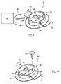
- Fig. 1 shows an exemplary embodiment of neurostimulation assembly 10.
- the neurostimulation assembly 10 is sized and configured so that, in use, it can be conveniently worn on a temporary basis.
- worn it is meant that the assembly 10 may be removably skin mounted (see Fig. 2A ), or may also be carried by the patient (i.e., user), or secured or strapped (see Fig. 2B ) to the patient's arm, leg, waist, clothing, a bed, or to movable devices to allow for patient mobility.
- the assembly 10 may be constructed in a manner to conform to the IPXB standard for water ingress.
- the assembly 10 may be constructed in a manner to conform to lower water ingress standards as well, for limited water contact applications.
- the neurostimulation assembly 10 is, in use, releasably coupled to a lead 12, including an extension lead 12, with the lead 12 coupled to electroce(s) 14 at connector 13.
- the electrodes 14 may be implanted, e.g., percutaneously, below the skin surface in a targeted tissue region or regions. The tissue region or regions are targeted prior to implantation of the electrodes 14 due to their muscular and/or neural morphologies in light of desired therapeutic and/or functional and/or diagnostic objectives.
- the neurostimulation assembly 10 In use, the neurostimulation assembly 10 generates and distributes electrical current patterns through the lead 12 to the electrodes 14 and back to a return electrode. In this way, the neurostimulation assembly 10 applies highly selective patterns of neurostimulation only to the targeted region or regions, to achieve one or more highly selective therapeutic and/or diagnostic outcomes.
- the inputs/stimulation parameters can vary according to desired therapeutic and/or diagnostic objectives.
- the outcomes can comprise the highly selective treatment of pain or muscle dysfunction, and/or the highly selective promotion of healing of tissue or bone, and/or the highly selective diagnosis of the effectiveness of a prospective functional electrical stimulation treatment.
- the neurostimulation assembly 10 will enable a physician to deliver a lead 12 and electrode 14, such as a fine wire percutaneous lead 12 and electrode(s) 14 to target locations via a hypodermic needle and send the patient home with a skin-mounted or carried or strapped miniature neurostimulation assembly 10.
- a lead 12 and electrode 14 such as a fine wire percutaneous lead 12 and electrode(s) 14
- the barriers associated with surface stimulation, including cutaneous pain and unreliable electrode placement are eliminated.
- the use of percutaneous electrodes allows the selective, comfortable, and consistent activation of the muscle(s) (and/or their innervating nerves) into which the electrode(s) 14 are implanted.
- the assembly 10 may enhance the ease of use of electrical stimulation therapy, improving clinical acceptance and patient compliance.
- the neurostimulation assembly 10 can incorporate various technical features to enhance its usability, which will now be described.
- the neurostimulation assembly 10 comprises a disposable patch or carrier 16.
- the carrier 16 desirably is sized and configured as a compact, lightweight, and flexible assembly made, e.g., of an inert, formed or machined plastic or metal material.
- the carrier 16 may be generally oval and measure about 50mm to about 80mm in height, and about 30mm to about 60mm in width, and about 10mm to about 20mm in depth, and more particularly about 60mm to about 70mm in height, and about 40mm to about 50mm in width, and about 12mm to about 18mm in depth, or more or less.
- the neurostimulation assembly 10 may weigh about 30 grams to about 50 grams, and more particularly about 40 grams, or more or less.
- he neurostimulation assembly 10 and associated carrier 16 may comprise a variety of sizes, shapes, and weights, for different applications and/or to increase or decrease the mounting surface area. At this size, the carrier 16 can be readily worn or carried without discomfort and in a cosmetically acceptable way (as Figs. 2A and 2B show).
- the flexible carrier material and shape will allow the neurostimulation assembly 10 to be positioned on curved surfaces of the body, such as an arm, shoulder, leg, stomach, and/or back, for example.
- the undersurface of the carrier 16 may include an adhesive region 17.
- the function of the optional adhesive region 17 is to temporarily secure the neurostimulation assembly 10 to an external skin surface during use.
- an inert, conventional pressure sensitive adhesive or tape can be used.
- the dermal adhesive region contains a bacteriostatic sealant that prevents skin irritation or superficial infection, which could lead to premature removal.
- covering bandage(s) 19 may be used to temporarily secure the neurostimulation assembly 10 in place on the external skin surface. Covering bandages 19 may also be used to temporarily secure an extension lead 12, and the electrode (s) 14 and the extension lead connector 13, to the skin surface. The use of one or more skin-like covering bandages 19 eliminates concerns over lead maintenance and keeps the assembly 10, extension lead 12, and electrodes 14 from snagging during bating, dressing, or personal grooming, for example.
- the assembly 10 may be held in place with the use of a strap 22.
- the strap may incorporate velco and/or elastic, for example, to allow flexibility and comfort when temporarily securing the neurostimulation assembly 10 to the desired body region.
- the carrier 16 carries an electronics pod 20, which generates the desired electrical current patterns and may incorporate a connector 29 for communication/programming with an external programming system or controller 46.
- the electronics pod 20 is removable and replaceable on the carrier 16. Having an electronics pod 20 that can be separated from the carrier 16 may be desired when the need to replace a carrier 16, or the electronics pod 20, during a course of treatment is necessary. For example, replacement of a carrier 16 without replacement of the electronics pod 20 may be desired if the anticipated length of use of the neurostimulation assembly 10 is going to be long enough to expect a degradation of adhesive properties of the adhesive region 17, (if used), or if the adhesive region 17 includes a return electrode, and may undergo, with use, degradation of adhesive properties and/or electrical conductivity.
- the electronics pod 20 houses microprocessor-based (microcontroller) circuitry 24 that generates stimulus waveforms, time or sequence stimulation pulses, logs and monitors usage, monitors system status, and can communicate directly to the clinician or indirectly through the use of an external programmer or controller.
- the stimulation desirably has a biphasic waveform (net DC current less than 10 microAmps), adjustable from about 0mA to about 20mA based on electrode type and the tissue type being stimulated, pulse durations adjustable from about 5 microseconds or less up to about 500 microseconds or more, and a frequency programmable from about 1Hz to about 3.50Hz. Most nuscle stimulation applications will be in the 10Hz to about 20Hz region, and pain management may use the higher frequencies.
- the stimulus current (amplitude) may be user selectable and the pulse duration may be limited to clinician selectable.
- the circuitry 24 desirably includes non-volatile memory, such as a flash memory device or an EEPRON memory chip to carry embedded, programmable code 26.
- the code 26 expresses the pre-programmed rules or algorithms under which the stimulation timing and command signals are generated.
- the circuitry 24 can be carried in a single location or at various locations in and/or on the pod 20, and/or return electrode 70, and may be fabricated on flexible or flex-rigid PC board using a very high density technique.
- the electronics pod 20 also includes one or more connectors 27, 28, 30.
- the function of the lead connector 27 is to physically and electrically couple the terminus of the return electrode 18 to the circuitry 24 of the electronics pod 20.
- the lead connector 27 comprises a pig-tail cable extending off the electronics pod 20 and ending with a connector 29. It is to be appreciated that the pig-tail cable could extend off the carrier 16 as well. It is also to be appreciated that the connector 29 could be integral with the electronics pod 20 or carrier 16 as well, i.e., without the pig-tail cable.
- Connector 28 physically and electrically couples the terminus of the lead 12, or extension if used, to the circuitry 24 of the electronics pod 20.
- the connector 28 is able to distribute the electrical current patterns in channels, i.e., each electrode 14 comprises a channel, so that highly selective stimulation patterns can be applied through multiple electrodes 14.
- One or more channels may be provided, i.e., two electrodes 14.
- Connector 30 may be provided as an option for physically and electrically coupling a communication/programming device 46 to the circuitry 24 of the electronics pod 20, i.e., connector 30 can serve as a communication interface. As Fig. 5 shows, the connector 30 can be used to couple to an external programming device or computer 46. Through this link 58, information and programming input can be exchanged and data can be downloaded from the electronics pod 20. This connector may be normally plugged with a rubber seal and only accessed during device communication/programming.
- a wireless link 59 e.g., RF magnetically coupled, infrared, or RF for example
- RF magnetically coupled, infrared, or RF could be used to place the electronics pod 20 in communication with an external programming device 46 or computer.
- the connectors 28, 29, and 30 may be touch proof and/or water proof connectors to help maintain a consistent and reliable electrical connection.
- Each connector may be labeled with a number or other indicia to identify the channel of the electronics circuitry 24 that is coupled to each connector.
- Coupling the extension lead 12, return electrode 18, 70, and device 46 to the electronics pod 20 or carrier 16 can be accomplished by a locking motion, a button, or a lever arm, or an Allen drive that is pushed, or slid, or pulled, or twisted, for example.
- the power source 32 can be described as a self-contained, limited life power source.
- the power source 32 may comprise one or more known power sources, such as capacitor(s) or battery(ies) 32, e.g., an alkaline, lithium, or Silver Oxide battery to provide the power to the electronics pod 20 (see Fig. 3 ).
- the power source may be selected based on the predetermined functional life of the assembly 10. As non-limiting examples, embodiments of the assembly 10 may be preconfigured for a functional life of one hour, day, week, month, year, two years, five years, or more or less.
- the power source 32 capacity may be sized to match the stimulation output capabilities of the assembly 10 for a predetermined amount of time, such as an hour, day, week, month, or year(s), for example.
- a predetermined amount of time such as an hour, day, week, month, or year(s), for example.
- one embodiment of the assembly 10 may be preconfigured for a functional life of two months.
- the power source 32 capacity would be sized to match the stimulation output capabilities of the assembly 10 for at least the two month period. It is to be appreciated that the neurostimulation assembly 10 may incorporate a wide range of power source capacities to reduce or extend the predetermined functional life of the assembly.
- the circuitry 24 may be used to electronically store information about the power source 32.
- the circuitry 24 may include a non-volatile memory 26 to store the power source and other information.
- the estimated remaining capacity of the power source 32 may be stored.
- the circuitry 24 may also identify the total power usage (service time) provided to date by the power source.
- the power source 32 may be non-replaceable, non-removable, and/or non-rechargeable.
- the neurostimulation assembly 10 may not require or allow the user to replace the power source 32 for the entire length of the temporary therapy, e.g., the power source capacity may be sized to function for the predetermined functional life of the assembly and/or the treatment period.
- Other external stimulators require that the user replace and/or recharge a battery as frequently as once per week. This task can be difficult for post-stroke patients who have compromised hand function on the hemiplegic side.
- the power source 32 may be inaccessible to battery replacement.
- the power source 32 may be secured within the electronics pod 20.
- the electronics pod 20 may comprise a molded plastic housing, the housing may include multiple pieces and may be made inaccessible by sonic welding, gluing, or other permanent fastening methods, to secure the housing together.
- a power budget for the circuitry 24 was developed based on the neurostimulation assembly's performance specifications and expected operating characteristics of the key circuit components (based on component specifications). Based on the power budget, a 500mA-hr to 600MA-hr primary cell battery may provide a service life sufficient for the neurostimulation assembly's performance specifications and expected operating characteristics, although it is to be appreciated that smaller and/or larger capacities may be used, such as from about 10mA-hr to about 1000mA-hr, or more or less. Combined with the desired size and shape of the neurostimulation assembly 10, Lithium primary cell types available from domestic suppliers were considered candidates.
- representative battery configurations include two L92 (AAA) 1.5V Li/FeS 2 cells in series (each cell is 10mm diameter x 44mm long); or four 1/3N (1/3 'N' cell size) 3.0V Li/MnO 2 cells in parallel -(each cell is 11.5mm diameter x 10.6mm long).
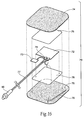
- the return electrode 70 i.e., surface electrode, includes an embedded power source 72, and optionally non-volatile memory, such as flash memory 73.
- the return electrode 70 is adapted to provide power and a return path, and optionally stimulus parameters stored in the memory 73, for the neurostimulation assembly 10.
- the return electrode 70 may be adapted to provide an electrical connection to the patient, and provide power to the neurostimulation assembly 10.
- the return electrode 70 shown in Fig. 16 comprises a top layer 74 and a bottom layer 75.
- the top and bottom layers nay be typical of the construction of TENS/NMES return surface electrodes.
- the top layer 74 may be an adhesive-backed fabric, for example, such as a non-woven (i.e., ncn-porous) medical tape.
- the bottom layer 75 may be a conductive hydrogel, which provides electrical contact and adhesion to the patient. The hydrogel may be selected to provide optimal adhesion and electrical properties for desired applications.
- the power source 72 may comprise a thin flexible power source, such as is available from Solicore (Lakeland, FL). As a non-limiting example, a 25x29x0.5mm flexible power source with a capacity of 10mA-hr may be used, although other dimensions and capacities are within the scope of the invention for a variety of applications (e.g., 1mA-hr to 1000mA-hr).
- the power source 72 and/or the optional flash memory 73 is/are positioned between the top and bottom layers 74, 75.
- the power source 72 and the optional flash memory 73 may also be sandwiched between one layer folded or two separate layers, for example, of non-conductive material 76, such as an envelope of flexible film. This sandwich of two non-conductive layers and the power source, and optional flash memory, may then be positioned between the top and bottom layers 74, 75.
- a cable assembly 77 may be electrically coupled, e.g., soldered, to exposed terminals 70 of the power source 72, which may also be laminated between the non-conductive material 76. Processes such as pressure-sensitive adhesive, overmolding or hot lamination may be used to achieve this state.
- One conductor 79 of the cable assembly 77 may comprise a carbon-fiber wire, for example, and may exit the laminated assembly and make intimate contact with the bottom hydrogel layer 75.
- the cable assembly 77 may also provide the electrical connection in common with the power source's negative contact.
- a connector 80 such as a touch proof and/or water proof connector 80, provides electrical contact between the neurostimulation assembly 10 and the return electrode 70.
- a flash memory chip 73 may be included in the return electrode 70.
- the memory 73 may, for example, provide a predetermined set of stimulus parameters for the neurostimulation assembly 10. This would allow the disposable power source/return electrode 70 to also provide the prescription of the stimulus to be delivered.
- the novel combination of a power source and return electrode allows the neurostimulation assembly 10 to be reduced in size as no internal power source is required for the assembly 10.
- the synergism of integrating the power source 72 with the return electrode 70 is clear as both may be limited life, disposable items.
- embedded memory 73 such as a flash memory chip, may permit the clinician to prescribe a predetermined set of stimulus parameters with just the selection of the proper return electrode.
- the return electrode with embedded power source takes advantage of one example of the usage of the neurostimulation assembly 10, wherein the patient may be changing their return electrode at predetermined periods, such as every day, or days, or week, or weeks, or months, to provide a renewed source of power with each application. This allows the neurostimulation assembly 10 to be used indefinitely, as long as a sufficient supply of return electrodes 70 is prescribed to the patient.
- the assembly 10 as shown in Figs. 1 and 3 desirably includes one or more features that provide an interface mechanism for the patient and/or the clinician.
- the interface feature allows for the input and output of neurostimulation assembly information, such as stimulus regime parameters and system status, and the interface may be manual, audio, or visual, or a combination.
- the electronics pod 20 may include control means 38, e.g., two button controls, to allow the patient to control stimulation amplitude setting or some other stimulus intensity adjustment (up-down; plus-minus; etc.).
- the electronics pod 20 may also be adapted to interface with a programming mode key 37, e.g., a magnet, or a paper clip access switch, for example, to provide control for the clinician to access clinician controllable settings through the control means 38, such as the stimulus pulse duration and/or stimulus frequency and/or stimulus amplitude, for example.
- a programming mode key 37 e.g., a magnet, or a paper clip access switch, for example, to provide control for the clinician to access clinician controllable settings through the control means 38, such as the stimulus pulse duration and/or stimulus frequency and/or stimulus amplitude, for example.
- the assembly 10 may include a slot or recess 39 adapted to accept the programming mode key 37.
- the programming mode key 37 desirably is in place in order to switch the neurostimulation assembly 10 into the programming mode and access clinician controllable settings.
- Table 1 below provides possible stimulus parameter settings. It is to be appreciated that more or less Stimulus Parameters, different ranges of Assembly Capabilities, and optional Methods of Programming are all possible. Table 1 is only intended as an example of possible settings and capabilities of the neurostimulation assembly 10.
- the clinician may be able to program the stimulus intensity by inserting the programming key 37 (e.g., a small magnet) into the slot 39 molded into the electronics pod 20. Once the key 37 is inserted, the clinician may use pushbuttons 38 on the assembly 10 to evaluate the patient's response to stimulus intensity settings preconfigured in the assembly.
- a display 40 e.g., an LCD or LED display on the top of the assembly shows the stimulus intensity being delivered. The clinician then selects the optimal stimulus intensity for the patient from the available settings.
- the neurostimulation assembly 10 When the programming key 37 is not inserted, the neurostimulation assembly 10 is in the patient mode and stimulus is automatically provided at the stimulus intensity programmed by the clinician.
- the patient can use the two pushbuttons 38 on top of the assembly to turn the stimulation off or make minor changes to the stimulus intensity programmed by the clinician.
- the particular setting level can be displayed using the display 40 to visually identify to the patient the setting level, and to allow the patient to record the setting within a therapy diary, which could then be presented to a physician for review.
- the operating modes and stimulus parameters may be entered manually using the control means 38 and/or 37, and easily interpreted via the visual output or feedback display 40.
- the setting level is a combination of pulse duration and amplitude, the specifics of which are unknown to the patient.
- the display 40 may also provide a data read-out function for the clinician. For example, the display 40 may provide information such as the total duration of stimulus provided, the average or median stimulus level selected by the patient, and perhaps the total duration of no stimulation provided.
- the display 40 may also provide status information, such as power source status or system status.
- the stimulation assembly 10 may indicate the power source 32 has limited power remaining, or that the power source has provided its maximum amount of power, as non-limiting examples.
- the stimulation assembly 10 may indicate the electrical connections to the extension lead 12, electrodes 14, or return electrode 18 are not working, as non-limiting examples.
- visual output or feedback may also be provided by an illuminating electronics pod 20, or portions of the electronics pod.
- the pod 20 may comprise a material, e.g., a semi-transparent material, able to allow an illumination source 42, such as one or more LEDs, to create a "glowing" or “illuminated” appearance.
- the illumination source 42 may be coupled to the circuitry 24 within the electronics pod 20.
- Status information can be visually provided to the user by using various blinking or pulsing configurations, illumination brightness, changing colors, or any combination, for example. As with the display 40, status information may include power source status and system status.
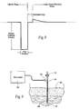
- Fig. 7 shows an embodiment of a block diagram circuit 90 for the neurostimulation assembly 10 that takes into account the desirable technical features of the neurostimulation assembly design discussed above.
- the circuit 90 can be grouped into functional blocks, which generally correspond to the association and interconnection of the electronic components.
- Fig. 7 five functional blocks are shown: (A) the Microprocessor Circuitry 24; (B) the Power Source 32; (C) the VHH Power Supply 94; (D) the Stimulus Output Stage(s) 96; and (E) the Output Multiplexer 98.
- the microcontroller circuitry 24 may be responsible for the following functions:
- microcontroller based circuitry incorporating flash programmable memory allows the operating software of the neurostimulator as well as the stimulus parameters and settings to be stored in non-volatile memory (data remains safely stored even when the power source 32, 72, becomes fully discharged or is removed).
- the non-volatile memory is also used to store usage history information, and may also be located in the return electrode 70.
- microcontroller circuit 24 may be a single component, the firmware may be developed as a number of separate modules that deal with specific needs and hardware peripherals. The functions and routines of these software modules may be executed sequentially; but the execution of these modules may be timed and coordinated so as to effectively function simultaneously. The microcontroller operations that are associated directly with a given hardware functional block are described with that block.
- the Components of the Microcontroller Circuit may include:
- the Power Source 32 and/or 72 may be responsible for the following functions:
- power management controls are generally included with the electronics pod 20.
- the circuitry 24 and/or return electrode 70 contains non-volatile memory, which is adapted to store power source usage information written by and read by the electronic pod 20.
- the VHH power supply 94 is generally responsible for the following functions:
- the Components of the VHH Power Supply might include:
- VHH internal stimulus power supply
- the actual voltage of the internal stimulus power supply (VHH) may be dynamically adjusted by the stimulator to provide a minimum, but adequate operating overhead voltage for the stimulus output stage 96, thus minimizing the battery power consumption.
- the impedance presented by the lead 12, electrode 14, and the electrode to tissue interface varies little over time, the tissue to electrode impedance of the surface mounted return electrode 18 may vary and represents the majority of the electrode circuit impedance.
- a conventional, single inductor, flyback boost converter circuit topology may be used for the identified supply and loading conditions. This component may be the Sipex SP6691, or comparable switch mode power supply.
- the Stimulus Output Stage(s) 96 is generally responsible for the following functions:
- the switched resistors could be replaced by a DAC, if available as an on-chip peripheral at the microcontroller.
- the start and ending of the cathodic phase current is timed by the microcontroller.
- the output multiplexer 98 is required only if more than one electrode circuit is required.
- the output multiplexer is responsible for routing the anode and cathode connections of the Stimulus Output Stage 96 to the appropriate electrode, i.e., electrode(s) 14, and possibly return electrode 18, or both.
- a representative output multiplexer configuration includes:
- the configuration of the electrodes 14 and the manner in which they are implanted can vary. A representative arrangement will be described, with reference to Figs. 9 to 11 .
- Each lead 12 may comprise a thin, flexible component made of a metal and/or polymer-material.
- the lead 12 may not be greater than about 0.75 mm (0.030 inch) in diameter, although the diameter may be larger or smaller.
- the lead 12 can comprise, e.g., one or more coiled metal wires with in an open or flexible elastomer core.
- the wire can be insulated, e.g., with a biocompatible polymer film, such as polyfluorocarbon, polyimide, or parylene.
- the lead 12 are desirably coated with a textured, bacteriostatic material, which helps to stabilize the electrode in a way that still permits easy removal at a later date and increases tolerance.
- the electrode 14 are electrically insulated everywhere except at one (monopolar), or two (bipolar), or three (tripolar), for example, conduction locations near its distal tip. Each of the conduction locations may be connected to one or more conductors that run the length of the lead 12, proving electrical continuity from the conduction location through the lead 12 to the electronics pod 2C.
- the conduction location may comprise a de-insulated area of an otherwise insulated conductor that runs the length of an entirely insulated electrode.
- the de-insulated conduction region of the conductor can be formed differently, e.g., it can be wound with a different pitch, or wound with a larger or smaller diameter, or molded to a different dimension.
- the conduction location of the electrode may comprise a separate material (e.g., metal or a conductive polymer) exposed to the body tissue to which the conductor of the wire is bonded.
- the lead 12 does not utilize an extension 12, rather the lead 12 is electrically connected to the electronics pod 20 or carrier 16 through an automated connection method that connects and terminates the electrode 14.
- the electrode (s) 14 and lead 12 are desirably provided in sterile packages and desirably possess mechanical properties in terms of flexibility and fatigue life that provide an operating life free of mechanical and/or electrical failure, taking into account the dynamics of the surrounding tissue (i.e., stretching, bending, pushing, pulling, crushing, etc.).
- the material of the electrode desirably discourages the in-growth of connective tissue along its length, so as not to inhibit its withdrawal at the end of its use. However, it may be desirable to encourage the in-growth of connective tissue at the distal tip of the electrode, to enhance its anchoring in tissue.
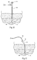
- the desired electrode 14 may also include, at its distal tip, an anchoring element 48 (see Figs. 10 and 11 ).
- the anchoring element 48 takes the form of a simple barb or bend.
- the anchoring element 48 is sized and configured so that, when in contact with tissue, it takes purchase in tissue, to resist dislodgement or migration of the electrode out of the correct location in the surrounding tissue.
- the anchoring element 48 is prevented from fully engaging body tissue until after the electrode 14 has been deployed. The electrode is not deployed until after it has been correctly located during the implantation (installation) process, as will be described in greater detail later.
- the lead 12 can include a metal stylet within its core. Movement of the stylet with respect to the body of the electrode and/or an associated introducer (if used) is used to deploy the electrode by exposing the anchoring element 48 to body tissue. In this arrangement, the stylet is removed once the electrode 14 is located in the desired region.
- an electrode 14 may be percutaneously implanted housed within electrode introducer 50 (i.e., a hypodermic needle).
- the electrode introducer 50 comprises a shaft having sharpened needle-like distal tip, which penetrates skin and tissue leading to the targeted tissue region.
- the lead 12 may be loaded (it may be preloaded and provided in a kit) within a lumen in the introducer 50, with the anchoring element 48 shielded from full tissue contact within the shaft of the introducer 50 (see Fig. 9 ).
- the introducer can be freely manipulated in tissue in search of a desired final electrode implantation site (see Fig. 10 ) before deploying the electrode and withdrawing the introducer 50 (see Fig. 11 ).
- the electrode introducer 50 may be insulated along the length of the shaft, except for those areas that correspond with the exposed conduction surfaces of the electrode 14 housed inside the introducer 50. These surfaces on the outside of the introducer 50 are electrically isolated from each other and from the shaft of the introducer 50. These surfaces may be electrically connected to a connector 64 at the end of the introducer body (sec Figs. 9 and 10 ). This allows connection to a stimulating circuit 66 (see Fig. 9 ) during the implantation process.
- the stimulating circuit 66 may comprise a stand along stimulator, or the neurostimulation assembly 10 may be the stimulating circuit. Applying stimulating current through the outside surfaces of the introducer 50 provides a close approximation to the response that the electrode 14 will provide when it is deployed at the current location of the introducer 50.
- the electrode introducer 50 is sized and configured to be bent by hand prior to its insertion through the skin. This will allow the physician to place an electrode 14 in a location that is not in an unobstructed straight line with the insertion site.
- the construction and materials of the electrode introducer 50 allow bending without interfering with the deployment of the lead 12 and withdrawal of the electrode introducer 50, leaving the electrode 14 in the tissue.
- a clinician Prior to installation, a clinician identifies a particular muscle(s) and/or neural region(s) to which a prescribed therapy using the neurostimulation assembly 10 will be applied. Once the particular muscle(s) and/or nerve(s) and/or tissue region or regions are identified, the clinician proceeds to percutaneously implant one or more electrodes 14 and leads 12, one by one, through the desired skin region 68. While each electrode 14 is implanted, the electrode introducer 50 applies a stimulation signal until a desired response is achieved indicating the desired placement, at which time the electrode 14 is deployed and the introducer 50 is withdrawn.
- the clinician Upon implanting each electrode (see Fig. 4 , for example), the clinician is able to route the extension lead 12, if used, to a lead connector 28 on the electronics pod 20 (or carrier 16).
- the following illustration will describe the use of a neurostimulator assembly 10 that will be carried or worn on the patient's exterior skin surface. It is to be appreciated that the neurostimulator assembly 10 could be carried by the patient or temporarily secured to a bed or other structure and the lead extensions 12 extend to the assembly 10.
- the assembly 10 is placed around an arm or leg (e.g., with the use of a strap), or on the skin in a desirable region, that allows electrical connectivity to the electrode(s) 14, lead 12, and associated connector 28 (see Figs. 2A through 3 ).
- the carrier 16 may be secured in place with pressure sensitive adhesive 18 on the bottom of the carrier 16, or held in place with a covering tape, or with a strap, as previously described.
- the adhesive region desirably contains a bacteriostatic sealant that prevents skin irritation or superficial infection, which could lead to premature removal.
- the clinician After implanting one or more electrodes 14 and placing a return electrode 18, 70, on the skin surface, the clinician would be able to route the lead 12 to the electronics pod 20, and couple the return electrode to the connector 29 to complete the stimulation path.
- the neurostimulation assembly 10 is ready for use.
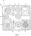
- kit 82 comprises a sterile, wrapped assembly.
- the kit 82 includes an interior tray 86 made, e.g., from die cut cardboard, plastic sheet, or thermo-formed plastic material, which hold the contents.
- Kit 82 also desirably includes instructions for use 56 for using the contents of the kit to carry out a desired therapeutic and/or diagnostic and/or functional objectives.
- the instructions 56 can, of course vary.
- the instructions 56 shall be physically present in the kits, but can also be supplied separately.
- the instructions 56 can be embodied in separate instruction manuals, or in video or audio tapes, CD's, and DVD's.
- the instructions 56 for use can also be available through an internet web page.
- kit 82 The arrangement and contents of the kit 82 can vary.
- Fig. 12 shows a kit 82 containing the neurostimulation assembly 10.
- the instructions for use 56 in the kit 82 may direct a clinician to place the neurostimulation assembly 10, implant the electrode 14, couple the electrode 14 to the lead 12, couple the lead 12 to the assembly 10, and place the return electrode 18 and couple the return electrode to the assembly 10.
- the instructions may also include instructions for the user in the operation of the neurostimulation assembly 10.
- Kit 82 may also include an extension lead 12, and one or more electrodes 14.
- external desktop or handheld (desirably also battery powered) preprogrammed and/or programmable instruments 46 can be used to program stimulus regimes and parameters into the neurostimulation assembly 10, or to download recorded data from the neurostimulation assembly 10 for display and further processing.
- Instructions for use 56 may describe options for the instruments 46 to communicate with the neurostimulation assembly 10, e.g., by a cable connection 58, wireless coupling 59, e.g., by radio frequency magnetic field coupling, by infrared, or by RF wireless, for example.
- the communications cable 58 may be adapted to provide power to the neurostimulation assembly 10 during programming, as well as communications with the circuitry 24 of the neurostimulation assembly 10.
- the external programming instrument 46 can also be a general purpose personal computer or personal digital device fitted with a suitable custom program and a suitable cable or interface box for connection to the communications cable 58.
- the programming instruments 46 allow a clinician one option for customizing the stimulus parameters and regime timing residing in an individual neurostimulation assembly 10 according the specific needs of the user and the treatment goals of the clinician.
- the neurostimulation assembly 10 can, once customized, be disconnected from the programming system, allowing portable, or skin worn operation, as already described.
- the programming instruments also allow the retrieval of usage information allowing the clinician to accurately assess patient compliance with the prescribed treatment course or regime.
- the clinician may use the push buttons 38, display 40, and/or access through the use of the programming mode key 37 to program the stimulus parameters and timing and to retrieve key usage data.
Landscapes
- Health & Medical Sciences (AREA)
- Life Sciences & Earth Sciences (AREA)
- Veterinary Medicine (AREA)
- Public Health (AREA)
- General Health & Medical Sciences (AREA)
- Animal Behavior & Ethology (AREA)
- Engineering & Computer Science (AREA)
- Biomedical Technology (AREA)
- Nuclear Medicine, Radiotherapy & Molecular Imaging (AREA)
- Radiology & Medical Imaging (AREA)
- Heart & Thoracic Surgery (AREA)
- Cardiology (AREA)
- Orthopedic Medicine & Surgery (AREA)
- Neurosurgery (AREA)
- Neurology (AREA)
- Physical Education & Sports Medicine (AREA)
- Biophysics (AREA)
- Chemical & Material Sciences (AREA)
- Chemical Kinetics & Catalysis (AREA)
- General Chemical & Material Sciences (AREA)
- Electrotherapy Devices (AREA)
Claims (15)
- Ensemble de neurostimulation (10) comprenant :au moins une électrode (14) dimensionnée et configurée pour une implantation dans une région cible de tissu neural ou musculaire ;un dispositif portatif (16) dimensionné et configuré pour être porté par le patient ;un module électronique (20) supporté de façon détachable sur le dispositif portatif, le module électronique comprenant des circuits (24) configurés pour générer une impulsion de stimulation ;un fil (12) électriquement couplé à l'électrode et comprenant un élément de connexion (28) adapté pour se coupler électriquement au module électronique ;une électrode de retour montable en surface (70), adaptée pour être couplée électriquement au module électronique, caractérisé en ce que l'électrode de retour montable en surface (70) comprend :une couche supérieure (74) et une couche inférieure (75), la couche inférieure étant adaptée pour fournir un contact électrique et une adhérence à un patient,une source de courant (72) positionnée entre la couche supérieure et la couche inférieure, et électriquement couplée à la couche inférieure et à un ensemble de câble (77), etun connecteur (80) électriquement couplé à l'ensemble de câble, l'ensemble de câble et le connecteur étant adaptés pour fournir un contact électrique entre la source de courant et le module électronique.
- Ensemble de neurostimulation selon la revendication 1, comprenant en outre :des instructions prescrivant le détachement et le remplacement de l'électrode de retour (70) en fonction d'un programme prédéfini ; etun élément de connexion d'électrode supporté sur le dispositif portatif (16), lequel est électriquement couplé au module électronique (20), l'élément de connexion d'électrode étant dimensionné et configuré pour engager électriquement l'élément de connexion de fil (28) pour coupler électriquement l'électrode (14) au module électronique afin d'appliquer de façon percutanée l'impulsion de stimulation à la région de tissu.
- Ensemble de neurostimulation selon la revendication 2, dans lequel le programme prédéfini comprend le remplacement de l'électrode de retour (18) répété au moins chaque jour ou semaine ou mois.
- Ensemble de neurostimulation selon l'une quelconque des revendications 1 à 3, dans lequel le module électronique supporté sur le dispositif portatif (16) est dimensionné et configuré pour être détaché sélectivement du dispositif portatif.
- Ensemble de neurostimulation selon l'une quelconque des revendications précédentes, dans lequel au moins un conducteur (79) de l'ensemble de câble (77) comprend un fil de fibres de carbone.
- Ensemble de neurostimulation selon la revendication 5, dans lequel le fil de fibres de carbone est adapté pour créer un contact étroit avec la couche inférieure (75).
- Ensemble de neurostimulation selon l'une quelconque des revendications précédentes, dans lequel la couche supérieure (74) de l'électrode de retour montable en surface (70) comprend un tissu à envers adhésif.
- Ensemble de neurostimulation selon l'une quelconque des revendications précédentes, dans lequel la couche inférieure (75) de l'électrode de retour montable en surface (70) comprend un matériau hydrogel conducteur, adapté pour être placé sur la peau.
- Ensemble de neurostimulation selon l'une quelconque des revendications précédentes, dans lequel la source de courant (72) de l'électrode de retour montable en surface (70) est prise en sandwich entre des couches de matériau non-conducteur (76).
- Ensemble de neurostimulation selon la revendication 9, dans lequel les couches de matériau non-conducteur (76) et la source de courant (72) prise en sandwich entre celles-ci sont prises en sandwich entre la couche supérieure (74) et la couche inférieure (75).
- Ensemble de neurostimulation selon l'une quelconque des revendications précédentes, dans lequel le connecteur (80) de l'électrode de retour montable en surface (70) est sûr au toucher et/ou imperméable à l'eau.
- Ensemble de neurostimulation selon l'une quelconque des revendications précédentes, dans lequel la source de courant (72) de l'électrode de retour montable en surface (70) comprend une source de courant flexible.
- Ensemble de neurostimulation selon l'une quelconque des revendications précédentes, dans lequel la source de courant (72) de l'électrode de retour montable en surface (70) présente une capacité entre environ 1 mAh et environ 1000 mAh.
- Ensemble de neurostimulation selon l'une quelconque des revendications précédentes, dans lequel la source de courant (72) de l'électrode de retour montable en surface (70) est non-rechargeable.
- Ensemble de neurostimulation selon l'une quelconque des revendications précédentes, comprenant en outre une mémoire non-volatile (73) positionnée entre la couche supérieure (74) et la couche inférieure (75) de l'électrode de retour montable en surface (70).
Applications Claiming Priority (2)
| Application Number | Priority Date | Filing Date | Title |
|---|---|---|---|
| US13765208P | 2008-08-01 | 2008-08-01 | |
| PCT/US2009/004440 WO2010014259A1 (fr) | 2008-08-01 | 2009-08-03 | Ensembles et systèmes portatifs permettant d'apporter une neurostimulation fonctionnelle ou thérapeutique et procédés associés |
Publications (3)
| Publication Number | Publication Date |
|---|---|
| EP2318088A1 EP2318088A1 (fr) | 2011-05-11 |
| EP2318088A4 EP2318088A4 (fr) | 2012-02-08 |
| EP2318088B1 true EP2318088B1 (fr) | 2016-02-17 |
Family
ID=41610659
Family Applications (1)
| Application Number | Title | Priority Date | Filing Date |
|---|---|---|---|
| EP09803285.7A Active EP2318088B1 (fr) | 2008-08-01 | 2009-08-03 | Ensembles et systèmes portatifs permettant d'apporter une neurostimulation fonctionnelle ou thérapeutique |
Country Status (6)
| Country | Link |
|---|---|
| US (2) | US8463383B2 (fr) |
| EP (1) | EP2318088B1 (fr) |
| JP (1) | JP5676445B2 (fr) |
| AU (1) | AU2009277036B2 (fr) |
| CA (1) | CA2732732C (fr) |
| WO (1) | WO2010014259A1 (fr) |
Cited By (8)
| Publication number | Priority date | Publication date | Assignee | Title |
|---|---|---|---|---|
| US9643022B2 (en) | 2013-06-17 | 2017-05-09 | Nyxoah SA | Flexible control housing for disposable patch |
| US9849289B2 (en) | 2009-10-20 | 2017-12-26 | Nyxoah SA | Device and method for snoring detection and control |
| US9855032B2 (en) | 2012-07-26 | 2018-01-02 | Nyxoah SA | Transcutaneous power conveyance device |
| US9943686B2 (en) | 2009-10-20 | 2018-04-17 | Nyxoah SA | Method and device for treating sleep apnea based on tongue movement |
| US10716560B2 (en) | 2012-07-26 | 2020-07-21 | Nyxoah SA | Implant unit delivery tool |
| US10751537B2 (en) | 2009-10-20 | 2020-08-25 | Nyxoah SA | Arced implant unit for modulation of nerves |
| US10814137B2 (en) | 2012-07-26 | 2020-10-27 | Nyxoah SA | Transcutaneous power conveyance device |
| US11253712B2 (en) | 2012-07-26 | 2022-02-22 | Nyxoah SA | Sleep disordered breathing treatment apparatus |
Families Citing this family (98)
| Publication number | Priority date | Publication date | Assignee | Title |
|---|---|---|---|---|
| US7871427B2 (en) | 2005-02-08 | 2011-01-18 | Carewave, Inc. | Apparatus and method for using a portable thermal device to reduce accommodation of nerve receptors |
| ES2827186T3 (es) | 2007-03-09 | 2021-05-20 | Mainstay Medical Ltd | Sistema de estimulación eléctrica neuromuscular |
| US11679261B2 (en) | 2007-03-09 | 2023-06-20 | Mainstay Medical Limited | Systems and methods for enhancing function of spine stabilization muscles associated with a spine surgery intervention |
| US11679262B2 (en) | 2007-03-09 | 2023-06-20 | Mainstay Medical Limited | Systems and methods for restoring muscle function to the lumbar spine |
| US10925637B2 (en) | 2010-03-11 | 2021-02-23 | Mainstay Medical Limited | Methods of implanting electrode leads for use with implantable neuromuscular electrical stimulator |
| US9072897B2 (en) | 2007-03-09 | 2015-07-07 | Mainstay Medical Limited | Systems and methods for restoring muscle function to the lumbar spine |
| US11331488B2 (en) | 2007-03-09 | 2022-05-17 | Mainstay Medical Limited | Systems and methods for enhancing function of spine stabilization muscles associated with a spine surgery intervention |
| US9089707B2 (en) | 2008-07-02 | 2015-07-28 | The Board Of Regents, The University Of Texas System | Systems, methods and devices for paired plasticity |
| US8457757B2 (en) | 2007-11-26 | 2013-06-04 | Micro Transponder, Inc. | Implantable transponder systems and methods |
| US8579953B1 (en) | 2007-12-07 | 2013-11-12 | Peter J. Dunbar | Devices and methods for therapeutic heat treatment |
| US8700177B2 (en) | 2008-08-01 | 2014-04-15 | Ndi Medical, Llc | Systems and methods for providing percutaneous electrical stimulation |
| JP5676445B2 (ja) | 2008-08-01 | 2015-02-25 | エヌディーアイ メディカル, エルエルシー | 機能的または治療的な神経刺激を提供する携帯型アセンブリ、システムおよび方法 |
| US8653365B1 (en) * | 2009-01-23 | 2014-02-18 | Claude W. Mixon | Overfill warning wiring system for tank trucks |
| US20110307042A1 (en) * | 2009-02-26 | 2011-12-15 | Opm Medical Acquisition, Llc | Electrode arrays based on polyetherketoneketone |
| CN103079633B (zh) | 2010-03-11 | 2016-05-04 | 梅恩斯塔伊医疗公司 | 用于治疗背痛的模块式刺激器、植入式rf消融系统及使用方法 |
| US9950159B2 (en) | 2013-10-23 | 2018-04-24 | Mainstay Medical Limited | Systems and methods for restoring muscle function to the lumbar spine and kits for implanting the same |
| US11786725B2 (en) | 2012-06-13 | 2023-10-17 | Mainstay Medical Limited | Systems and methods for restoring muscle function to the lumbar spine and kits for implanting the same |
| US9999763B2 (en) | 2012-06-13 | 2018-06-19 | Mainstay Medical Limited | Apparatus and methods for anchoring electrode leads adjacent to nervous tissue |
| US11684774B2 (en) | 2010-03-11 | 2023-06-27 | Mainstay Medical Limited | Electrical stimulator for treatment of back pain and methods of use |
| EP2563456B1 (fr) * | 2010-04-27 | 2020-06-03 | SPR Therapeutics, Inc. | Systèmes et procédés pour une stimulation électrique percutanée |
| EP2407193A1 (fr) * | 2010-07-12 | 2012-01-18 | Roche Diagnostics GmbH | Dispositif médical doté d'un boîtier en plusieurs parties |
| US8788047B2 (en) | 2010-11-11 | 2014-07-22 | Spr Therapeutics, Llc | Systems and methods for the treatment of pain through neural fiber stimulation |
| US8788046B2 (en) | 2010-11-11 | 2014-07-22 | Spr Therapeutics, Llc | Systems and methods for the treatment of pain through neural fiber stimulation |
| US8788048B2 (en) | 2010-11-11 | 2014-07-22 | Spr Therapeutics, Llc | Systems and methods for the treatment of pain through neural fiber stimulation |
| AU2011336269B2 (en) | 2010-12-03 | 2016-05-12 | Spr Therapeutics, Inc. | Systems and methods for treating shoulder pain related to subacromial impingement syndrome |
| EP2665457B1 (fr) | 2011-01-21 | 2019-06-12 | Carewave Medical, Inc. | Système d'application de stimulation par modules |
| US20130197607A1 (en) | 2011-06-28 | 2013-08-01 | Greatbatch Ltd. | Dual patient controllers |
| US20130006330A1 (en) | 2011-06-28 | 2013-01-03 | Greatbatch, Ltd. | Dual patient controllers |
| US8954148B2 (en) | 2011-06-28 | 2015-02-10 | Greatbatch, Ltd. | Key fob controller for an implantable neurostimulator |
| US8668344B2 (en) | 2011-11-30 | 2014-03-11 | Izi Medical Products | Marker sphere including edged opening to aid in molding |
| US8661573B2 (en) | 2012-02-29 | 2014-03-04 | Izi Medical Products | Protective cover for medical device having adhesive mechanism |
| US10632309B2 (en) | 2012-03-15 | 2020-04-28 | Spr Therapeutics, Inc. | Systems and methods related to the treatment of back pain |
| WO2013162709A1 (fr) | 2012-04-26 | 2013-10-31 | Medtronic, Inc. | Systèmes de stimulation d'essai |
| EP2841156A1 (fr) * | 2012-04-26 | 2015-03-04 | Medtronic, Inc. | Systèmes de stimulation d'essai |
| EP2841150B1 (fr) * | 2012-04-26 | 2020-09-30 | Medtronic, Inc. | Systèmes de stimulation d'essai |
| US8903502B2 (en) * | 2012-05-21 | 2014-12-02 | Micron Devices Llc | Methods and devices for modulating excitable tissue of the exiting spinal nerves |
| US9186501B2 (en) | 2012-06-13 | 2015-11-17 | Mainstay Medical Limited | Systems and methods for implanting electrode leads for use with implantable neuromuscular electrical stimulator |
| US10195419B2 (en) | 2012-06-13 | 2019-02-05 | Mainstay Medical Limited | Electrode leads for use with implantable neuromuscular electrical stimulator |
| AU2013277814B2 (en) * | 2012-06-21 | 2015-09-24 | Neuronano Ab | Medical microelectrode, method for its manufacture, and use thereof |
| US10485972B2 (en) | 2015-02-27 | 2019-11-26 | Thync Global, Inc. | Apparatuses and methods for neuromodulation |
| US9399126B2 (en) | 2014-02-27 | 2016-07-26 | Thync Global, Inc. | Methods for user control of neurostimulation to modify a cognitive state |
| US10537703B2 (en) | 2012-11-26 | 2020-01-21 | Thync Global, Inc. | Systems and methods for transdermal electrical stimulation to improve sleep |
| US10814131B2 (en) | 2012-11-26 | 2020-10-27 | Thync Global, Inc. | Apparatuses and methods for neuromodulation |
| US9440070B2 (en) * | 2012-11-26 | 2016-09-13 | Thyne Global, Inc. | Wearable transdermal electrical stimulation devices and methods of using them |
| US20160184602A1 (en) * | 2013-02-13 | 2016-06-30 | Habalan Med & Beauty Co., Ltd. | Portable high-frequency therapeutic apparatus having internal battery |
| US9962546B2 (en) * | 2013-02-21 | 2018-05-08 | Meagan Medical, Inc. | Cutaneous field stimulation with disposable and rechargeable components |
| US11229789B2 (en) | 2013-05-30 | 2022-01-25 | Neurostim Oab, Inc. | Neuro activator with controller |
| KR102390107B1 (ko) | 2013-05-30 | 2022-04-25 | 그라함 에이치. 크리시 | 국부 신경 자극 |
| EP3007759A4 (fr) * | 2013-06-13 | 2017-03-08 | DyAnsys, Inc. | Méthode et appareil d'électrothérapie de stimulation |
| US10052257B2 (en) | 2013-06-13 | 2018-08-21 | Dyansys, Inc. | Method and apparatus for stimulative electrotherapy |
| US10130275B2 (en) | 2013-06-13 | 2018-11-20 | Dyansys, Inc. | Method and apparatus for autonomic nervous system sensitivity-point testing |
| BR112015031151B1 (pt) * | 2013-06-13 | 2022-09-06 | Dyansys, Inc | Aparelho de teste elétrico e método para teste elétrico |
| US10293161B2 (en) | 2013-06-29 | 2019-05-21 | Thync Global, Inc. | Apparatuses and methods for transdermal electrical stimulation of nerves to modify or induce a cognitive state |
| US20150018911A1 (en) | 2013-07-02 | 2015-01-15 | Greatbatch Ltd. | Apparatus, system, and method for minimized energy in peripheral field stimulation |
| US10610690B2 (en) * | 2013-07-12 | 2020-04-07 | Pacesetter, Inc. | Fully implantable trial neurostimulation system configured for minimally-intrusive implant/explant |
| US9474634B2 (en) | 2013-10-22 | 2016-10-25 | Massachusetts Institute Of Technology | Peripheral neural interface via nerve regeneration to distal tissues |
| EP3148639A4 (fr) | 2014-05-17 | 2018-04-18 | Cerevast Medical Inc. | Méthodes et appareils utilisés pour l'application de formes d'onde par neurostimulation transcutanée |
| KR20170063440A (ko) | 2014-05-25 | 2017-06-08 | 하이인 에쿼티 인베스트먼트 펀드 엘.피. | 웨어러블 경피 신경자극기들 |
| US9802051B2 (en) * | 2014-08-15 | 2017-10-31 | Axonics Modulation Technologies, Inc. | External pulse generator device and associated methods for trial nerve stimulation |
| KR20170047300A (ko) | 2014-08-26 | 2017-05-04 | 아벤트, 인크. | 선택적 신경 섬유 차단 방법 및 시스템 |
| US10471268B2 (en) | 2014-10-16 | 2019-11-12 | Mainstay Medical Limited | Systems and methods for monitoring muscle rehabilitation |
| EP3223904B1 (fr) | 2014-11-26 | 2019-11-27 | SPR Therapeutics, Inc. | Stimulateur électrique pour une stimulation périphérique |
| WO2016109851A1 (fr) | 2015-01-04 | 2016-07-07 | Thync, Inc. | Procédés et appareils de stimulation transdermique de l'oreille externe |
| US11534608B2 (en) | 2015-01-04 | 2022-12-27 | Ist, Llc | Methods and apparatuses for transdermal stimulation of the outer ear |
| US10258788B2 (en) | 2015-01-05 | 2019-04-16 | Thync Global, Inc. | Electrodes having surface exclusions |
| CA2975074C (fr) * | 2015-02-03 | 2020-10-27 | Jongju Na | Appareil de traitement de vaisseaux sanguins dans la peau |
| US11077301B2 (en) | 2015-02-21 | 2021-08-03 | NeurostimOAB, Inc. | Topical nerve stimulator and sensor for bladder control |
| US20220062621A1 (en) | 2015-02-24 | 2022-03-03 | Elira, Inc. | Electrical Stimulation-Based Weight Management System |
| US10118035B2 (en) | 2015-02-24 | 2018-11-06 | Elira, Inc. | Systems and methods for enabling appetite modulation and/or improving dietary compliance using an electro-dermal patch |
| US10376145B2 (en) | 2015-02-24 | 2019-08-13 | Elira, Inc. | Systems and methods for enabling a patient to achieve a weight loss objective using an electrical dermal patch |
| US10335302B2 (en) | 2015-02-24 | 2019-07-02 | Elira, Inc. | Systems and methods for using transcutaneous electrical stimulation to enable dietary interventions |
| US9956393B2 (en) | 2015-02-24 | 2018-05-01 | Elira, Inc. | Systems for increasing a delay in the gastric emptying time for a patient using a transcutaneous electro-dermal patch |
| US10864367B2 (en) | 2015-02-24 | 2020-12-15 | Elira, Inc. | Methods for using an electrical dermal patch in a manner that reduces adverse patient reactions |
| US10765863B2 (en) | 2015-02-24 | 2020-09-08 | Elira, Inc. | Systems and methods for using a transcutaneous electrical stimulation device to deliver titrated therapy |
| CN107847732A (zh) | 2015-05-29 | 2018-03-27 | 赛威医疗公司 | 用于经皮电刺激的方法和装置 |
| WO2017106878A1 (fr) | 2015-12-18 | 2017-06-22 | Thync Global, Inc. | Appareils et procédés de stimulation électrique transdermique de nerfs pour modifier ou induire un état cognitif |
| US9956405B2 (en) | 2015-12-18 | 2018-05-01 | Thyne Global, Inc. | Transdermal electrical stimulation at the neck to induce neuromodulation |
| US11179251B2 (en) | 2016-01-08 | 2021-11-23 | Massachusetts Institute Of Technology | Method and system for providing proprioceptive feedback and functionality mitigating limb pathology |
| CA3014195A1 (fr) * | 2016-02-12 | 2017-08-17 | Axonics Modulation Technologies, Inc. | Dispositif generateur d'impulsions externes et procedes associes pour une stimulation nerveuse d'essai |
| USD775361S1 (en) * | 2016-04-01 | 2016-12-27 | Michael J. Vosch | Electrode patch array |
| US10646708B2 (en) | 2016-05-20 | 2020-05-12 | Thync Global, Inc. | Transdermal electrical stimulation at the neck |
| KR101874921B1 (ko) | 2016-05-31 | 2018-07-05 | 전자부품연구원 | 경골신경 자극술을 위한 배뇨장애 치료기기 |
| US10327810B2 (en) | 2016-07-05 | 2019-06-25 | Mainstay Medical Limited | Systems and methods for enhanced implantation of electrode leads between tissue layers |
| US11540973B2 (en) | 2016-10-21 | 2023-01-03 | Spr Therapeutics, Llc | Method and system of mechanical nerve stimulation for pain relief |
| US11247045B2 (en) | 2017-10-25 | 2022-02-15 | Epineuron Technologies Inc. | Systems and methods for delivering neuroregenerative therapy |
| US10589089B2 (en) | 2017-10-25 | 2020-03-17 | Epineuron Technologies Inc. | Systems and methods for delivering neuroregenerative therapy |
| EP3706856A4 (fr) | 2017-11-07 | 2021-08-18 | Neurostim Oab, Inc. | Activateur de nerf non invasif à circuit adaptatif |
| CN107875514B (zh) * | 2017-12-14 | 2019-04-23 | 苏州大学 | 一种用于缓解术前以及产前焦虑的功能电刺激装置 |
| US10780270B2 (en) | 2018-03-15 | 2020-09-22 | Avent, Inc. | System and method to percutaneously block painful sensations |
| US11278724B2 (en) | 2018-04-24 | 2022-03-22 | Thync Global, Inc. | Streamlined and pre-set neuromodulators |
| USD904629S1 (en) * | 2018-08-16 | 2020-12-08 | Spr Therapeutics, Inc. | Electrical stimulator |
| US11623091B2 (en) | 2019-02-13 | 2023-04-11 | Avent, Inc. | Portable electrical stimulation system and method |
| US11848090B2 (en) | 2019-05-24 | 2023-12-19 | Axonics, Inc. | Trainer for a neurostimulator programmer and associated methods of use with a neurostimulation system |
| ES2798182B2 (es) * | 2019-06-06 | 2021-04-22 | Univ Pablo De Olavide | Sistema para la neuroestimulación |
| CN114126704A (zh) | 2019-06-26 | 2022-03-01 | 神经科学技术有限责任公司 | 具有自适应电路的非侵入性神经激活器 |
| CN110477867A (zh) * | 2019-08-19 | 2019-11-22 | 中山大学 | 一种动物电刺激疼痛评估测试系统及评估测试方法 |
| US11364381B2 (en) | 2019-10-01 | 2022-06-21 | Epineuron Technologies Inc. | Methods for delivering neuroregenerative therapy and reducing post-operative and chronic pain |
| JP2023506713A (ja) | 2019-12-16 | 2023-02-20 | ニューロスティム テクノロジーズ エルエルシー | 昇圧電荷送達を用いた非侵襲性神経アクティベータ |
Family Cites Families (71)
| Publication number | Priority date | Publication date | Assignee | Title |
|---|---|---|---|---|
| US3939841A (en) | 1974-03-06 | 1976-02-24 | Dohring Albert A | Acupuncture needle guide and restraint |
| US3943932A (en) | 1975-01-17 | 1976-03-16 | Yen Kong Woo | Acupuncture needles and holder |
| JPS56501274A (fr) | 1979-10-10 | 1981-09-10 | ||
| US4416276A (en) * | 1981-10-26 | 1983-11-22 | Valleylab, Inc. | Adaptive, return electrode monitoring system |
| US4512351A (en) | 1982-11-19 | 1985-04-23 | Cordis Corporation | Percutaneous lead introducing system and method |
| US5167229A (en) | 1986-03-24 | 1992-12-01 | Case Western Reserve University | Functional neuromuscular stimulation system |
| JPH04102463A (ja) * | 1990-08-21 | 1992-04-03 | Tokyo Electric Co Ltd | 低周波治療器 |
| JP2570823Y2 (ja) * | 1991-12-06 | 1998-05-13 | 久光製薬株式会社 | プラスター形状の低周波治療器 |
| SE9201453L (sv) | 1992-05-08 | 1993-07-12 | Jens Schouenborg | Medicinsk anordning foer lindring av smaerttillstaand innefattande en elektrodplatta |
| US5397338A (en) | 1993-03-29 | 1995-03-14 | Maven Labs, Inc. | Electrotherapy device |
| US5549655A (en) | 1994-09-21 | 1996-08-27 | Medtronic, Inc. | Method and apparatus for synchronized treatment of obstructive sleep apnea |
| JPH08227428A (ja) * | 1995-02-20 | 1996-09-03 | Matsushita Electric Ind Co Ltd | プリント基板cad装置 |
| EP0743533A3 (fr) | 1995-05-16 | 1997-04-16 | Hewlett Packard Co | Dispositif électronique à batterie et à échange d'information avec la boîte aux lettres électronique d'une batterie |
| US5607461A (en) | 1995-10-20 | 1997-03-04 | Nexmed, Inc. | Apparatus and method for delivering electrical stimulus to tissue |
| US5721482A (en) | 1996-01-16 | 1998-02-24 | Hewlett-Packard Company | Intelligent battery and method for providing an advance low battery warning for a battery powered device such as a defibrillator |
| US6108579A (en) | 1996-04-15 | 2000-08-22 | Pacesetter, Inc. | Battery monitoring apparatus and method for programmers of cardiac stimulating devices |
| US6366809B1 (en) | 1997-04-08 | 2002-04-02 | Survivalink Corporation | Defibrillator battery with memory and status indication guage |
| US5861015A (en) | 1997-05-05 | 1999-01-19 | Benja-Athon; Anuthep | Modulation of the nervous system for treatment of pain and related disorders |
| US5861016A (en) | 1997-05-28 | 1999-01-19 | Swing; Fred P. | Method of wound healing using electrical stimulation and acupuncture needles |
| US6016449A (en) | 1997-10-27 | 2000-01-18 | Neuropace, Inc. | System for treatment of neurological disorders |
| US5857968A (en) | 1997-11-24 | 1999-01-12 | Benja-Athon; Anuthep | Coupling device in electroacupuncture |
| US6072299A (en) | 1998-01-26 | 2000-06-06 | Medtronic Physio-Control Manufacturing Corp. | Smart battery with maintenance and testing functions |
| US6020082A (en) | 1998-02-19 | 2000-02-01 | Summit Microelectronics, Inc. | Integrated battery identification system and method for determination of battery type and voltage level operability |
| FR2775592B1 (fr) | 1998-03-06 | 2000-06-16 | Patrick Cazaux | Appareil portable d'acupuncture |
| CN1272798A (zh) | 1998-06-03 | 2000-11-08 | 神经调节公司 | 经皮肌内刺激系统 |
| US6845271B2 (en) | 1998-06-03 | 2005-01-18 | Neurocontrol Corporation | Treatment of shoulder dysfunction using a percutaneous intramuscular stimulation system |
| US6016451A (en) | 1998-06-24 | 2000-01-18 | Sanchez-Rodarte; Salvador | Neurological stabilizer device |
| ATE297786T1 (de) | 1998-08-03 | 2005-07-15 | Amei Technologies Inc | Pemf-vorrichtung zur behandlung der osteoporose und zur stimulation des wachstums von geweben |
| EP1115454B1 (fr) | 1998-08-31 | 2006-10-25 | Travanti Pharma Inc | Systeme d'administration commandee de dose de medicament |
| US5948006A (en) | 1998-10-14 | 1999-09-07 | Advanced Bionics Corporation | Transcutaneous transmission patch |
| US6275737B1 (en) * | 1998-10-14 | 2001-08-14 | Advanced Bionics Corporation | Transcutaneous transmission pouch |
| US20030212440A1 (en) * | 2002-05-09 | 2003-11-13 | Boveja Birinder R. | Method and system for modulating the vagus nerve (10th cranial nerve) using modulated electrical pulses with an inductively coupled stimulation system |
| US6208902B1 (en) | 1998-10-26 | 2001-03-27 | Birinder Bob Boveja | Apparatus and method for adjunct (add-on) therapy for pain syndromes utilizing an implantable lead and an external stimulator |
| US6257906B1 (en) | 1999-02-08 | 2001-07-10 | 3Com Corporation | Functionally illuminated electronic connector with improved light dispersion |
| US6200265B1 (en) | 1999-04-16 | 2001-03-13 | Medtronic, Inc. | Peripheral memory patch and access method for use with an implantable medical device |
| US6445955B1 (en) | 1999-07-08 | 2002-09-03 | Stephen A. Michelson | Miniature wireless transcutaneous electrical neuro or muscular-stimulation unit |
| US6607500B2 (en) | 1999-07-08 | 2003-08-19 | Cyclotec Advanced Medical Technologies, Inc. | Integrated cast and muscle stimulation system |
| US20020019652A1 (en) | 1999-07-08 | 2002-02-14 | Cyclotec Advanced Medical Technologies | Two part tens bandage |
| US6904324B2 (en) | 1999-12-01 | 2005-06-07 | Meagan Medical, Inc. | Method and apparatus for deploying a percutaneous probe |
| JP2001190696A (ja) | 2000-01-07 | 2001-07-17 | Seiko Instruments Inc | 携帯型情報処理装置、情報処理方法およびその方法をコンピュータに実行させるプログラムを記録したコンピュータ読み取り可能な記録媒体 |
| US6974411B2 (en) | 2000-04-03 | 2005-12-13 | Neoguide Systems, Inc. | Endoscope with single step guiding apparatus |
| US6338347B1 (en) | 2000-04-04 | 2002-01-15 | Yun-Yin Chung | Blood circulation stimulator |
| JP2001286569A (ja) | 2000-04-05 | 2001-10-16 | Polytronics Ltd | 経皮投薬装置 |
| US6606519B2 (en) * | 2000-06-16 | 2003-08-12 | Newcare Products, Llc | Microcurrent therapy device components stack and conductive pad |
| US6687538B1 (en) | 2000-06-19 | 2004-02-03 | Medtronic, Inc. | Trial neuro stimulator with lead diagnostics |
| US6544189B2 (en) * | 2000-09-25 | 2003-04-08 | Zargis Medical Corp. | Handheld sensor for acoustic data acquisition |
| US6530914B1 (en) | 2000-10-24 | 2003-03-11 | Scimed Life Systems, Inc. | Deflectable tip guide in guide system |
| DE20200685U1 (de) | 2001-08-17 | 2002-03-28 | Hoeven Martin V D | Vorrichtung zur Elektrostimulation von Muskeln |
| US6955864B1 (en) | 2001-09-21 | 2005-10-18 | Defibtech, Llc | Medical device battery pack with active status indication |
| AU2002334749A1 (en) | 2001-09-28 | 2003-04-07 | Northstar Neuroscience, Inc. | Methods and implantable apparatus for electrical therapy |
| CA2461934A1 (fr) | 2001-09-28 | 2003-04-03 | Meagan Medical, Inc. | Procede et appareil de commande de signaux electriques percutanes |
| CA2408656C (fr) * | 2001-10-17 | 2016-06-21 | Rehabilicare, Inc. | Neurostimulateur electrique |
| EP2308553B1 (fr) * | 2001-10-18 | 2014-01-29 | Uroplasty, Inc. | Système de neurostimulation électrique |
| US20030176908A1 (en) | 2002-03-18 | 2003-09-18 | Hsin-Yi Lin | Water-impregnable electrode for electrical stimulation device |
| US20050165458A1 (en) * | 2002-05-09 | 2005-07-28 | Boveja Birinder R. | Method and system to provide therapy for depression using electroconvulsive therapy(ECT) and pulsed electrical stimulation to vagus nerve(s) |
| AU2003241668A1 (en) * | 2002-06-19 | 2004-01-06 | Matsushita Electric Industrial Co., Ltd. | Flexible ptc heating element and method of manufacturing the heating element |
| US20040230229A1 (en) * | 2003-04-11 | 2004-11-18 | Lovett Eric G. | Hybrid transthoracic/intrathoracic cardiac stimulation devices and methods |
| US20080097564A1 (en) | 2003-07-18 | 2008-04-24 | Peter Lathrop | Electrotherapeutic Device |
| EP1673139A2 (fr) * | 2003-09-10 | 2006-06-28 | Power Paper Ltd. | Bandage electrique |
| US7343202B2 (en) | 2004-02-12 | 2008-03-11 | Ndi Medical, Llc. | Method for affecting urinary function with electrode implantation in adipose tissue |
| US8086318B2 (en) * | 2004-02-12 | 2011-12-27 | Ndi Medical, Llc | Portable assemblies, systems, and methods for providing functional or therapeutic neurostimulation |
| US7120499B2 (en) | 2004-02-12 | 2006-10-10 | Ndi Medical, Llc | Portable percutaneous assemblies, systems and methods for providing highly selective functional or therapeutic neuromuscular stimulation |
| ATE520440T1 (de) | 2004-02-12 | 2011-09-15 | Ndi Medical Llc | Tragbare anordnungen und systeme für die funktionale oder therapeutische neuromuskuläre stimulation |
| US20080161874A1 (en) | 2004-02-12 | 2008-07-03 | Ndi Medical, Inc. | Systems and methods for a trial stage and/or long-term treatment of disorders of the body using neurostimulation |
| AU2005254016A1 (en) | 2004-06-10 | 2005-12-29 | Ndi Medical, Llc | Systems and methods for bilateral stimulation of left and right branches of the dorsal genital nerves to treat dysfunctions, such as urinary incontinence |
| WO2005123181A2 (fr) | 2004-06-10 | 2005-12-29 | Ndi Medical, Llc | Generateur d'impulsions implantable destine a fournir une stimulation fonctionnelle et/ou therapeutique des muscles et/ou des nerfs et/ou des tissus du systeme nerveux central |
| US7654956B2 (en) * | 2004-07-13 | 2010-02-02 | Dexcom, Inc. | Transcutaneous analyte sensor |
| US8244335B2 (en) * | 2006-02-06 | 2012-08-14 | The Board Of Trustees Of The Leland Stanford Junior University | Non-invasive cardiac monitor and methods of using continuously recorded cardiac data |
| JP2009537226A (ja) * | 2006-05-18 | 2009-10-29 | エヌディーアイ メディカル, エルエルシー | 機能的または治療的神経刺激を提供する携帯アッセンブリ、システム、および方法 |
| JP4125339B2 (ja) * | 2006-10-06 | 2008-07-30 | エヌディーアイ メディカル, エルエルシー | 機能的または治療的神経筋刺激を提供するための携帯式アセンブリ、システムおよび方法 |
| JP5676445B2 (ja) | 2008-08-01 | 2015-02-25 | エヌディーアイ メディカル, エルエルシー | 機能的または治療的な神経刺激を提供する携帯型アセンブリ、システムおよび方法 |
-
2009
- 2009-08-03 JP JP2011521131A patent/JP5676445B2/ja active Active
- 2009-08-03 CA CA2732732A patent/CA2732732C/fr active Active
- 2009-08-03 EP EP09803285.7A patent/EP2318088B1/fr active Active
- 2009-08-03 AU AU2009277036A patent/AU2009277036B2/en active Active
- 2009-08-03 US US12/462,384 patent/US8463383B2/en active Active
- 2009-08-03 WO PCT/US2009/004440 patent/WO2010014259A1/fr active Search and Examination
-
2013
- 2013-06-10 US US13/913,798 patent/US20140058495A1/en not_active Abandoned
Cited By (18)
| Publication number | Priority date | Publication date | Assignee | Title |
|---|---|---|---|---|
| US10751537B2 (en) | 2009-10-20 | 2020-08-25 | Nyxoah SA | Arced implant unit for modulation of nerves |
| US11857791B2 (en) | 2009-10-20 | 2024-01-02 | Nyxoah SA | Arced implant unit for modulation of nerves |
| US11273307B2 (en) | 2009-10-20 | 2022-03-15 | Nyxoah SA | Method and device for treating sleep apnea |
| US10898717B2 (en) | 2009-10-20 | 2021-01-26 | Nyxoah SA | Device and method for snoring detection and control |
| US9950166B2 (en) | 2009-10-20 | 2018-04-24 | Nyxoah SA | Acred implant unit for modulation of nerves |
| US9943686B2 (en) | 2009-10-20 | 2018-04-17 | Nyxoah SA | Method and device for treating sleep apnea based on tongue movement |
| US9849289B2 (en) | 2009-10-20 | 2017-12-26 | Nyxoah SA | Device and method for snoring detection and control |
| US10716940B2 (en) | 2009-10-20 | 2020-07-21 | Nyxoah SA | Implant unit for modulation of small diameter nerves |
| US9855032B2 (en) | 2012-07-26 | 2018-01-02 | Nyxoah SA | Transcutaneous power conveyance device |
| US10716560B2 (en) | 2012-07-26 | 2020-07-21 | Nyxoah SA | Implant unit delivery tool |
| US10918376B2 (en) | 2012-07-26 | 2021-02-16 | Nyxoah SA | Therapy protocol activation triggered based on initial coupling |
| US11253712B2 (en) | 2012-07-26 | 2022-02-22 | Nyxoah SA | Sleep disordered breathing treatment apparatus |
| US10814137B2 (en) | 2012-07-26 | 2020-10-27 | Nyxoah SA | Transcutaneous power conveyance device |
| US11730469B2 (en) | 2012-07-26 | 2023-08-22 | Nyxoah SA | Implant unit delivery tool |
| US10512782B2 (en) | 2013-06-17 | 2019-12-24 | Nyxoah SA | Remote monitoring and updating of a medical device control unit |
| US11298549B2 (en) | 2013-06-17 | 2022-04-12 | Nyxoah SA | Control housing for disposable patch |
| US11642534B2 (en) | 2013-06-17 | 2023-05-09 | Nyxoah SA | Programmable external control unit |
| US9643022B2 (en) | 2013-06-17 | 2017-05-09 | Nyxoah SA | Flexible control housing for disposable patch |
Also Published As
| Publication number | Publication date |
|---|---|
| EP2318088A4 (fr) | 2012-02-08 |
| US20140058495A1 (en) | 2014-02-27 |
| CA2732732C (fr) | 2016-04-12 |
| AU2009277036A1 (en) | 2010-02-04 |
| WO2010014259A1 (fr) | 2010-02-04 |
| AU2009277036B2 (en) | 2016-03-03 |
| EP2318088A1 (fr) | 2011-05-11 |
| US8463383B2 (en) | 2013-06-11 |
| JP5676445B2 (ja) | 2015-02-25 |
| CA2732732A1 (fr) | 2010-02-04 |
| JP2011529718A (ja) | 2011-12-15 |
| US20100036445A1 (en) | 2010-02-11 |
Similar Documents
| Publication | Publication Date | Title |
|---|---|---|
| EP2318088B1 (fr) | Ensembles et systèmes portatifs permettant d'apporter une neurostimulation fonctionnelle ou thérapeutique | |
| US8086318B2 (en) | Portable assemblies, systems, and methods for providing functional or therapeutic neurostimulation | |
| EP2563456B1 (fr) | Systèmes et procédés pour une stimulation électrique percutanée | |
| US6381496B1 (en) | Parameter context switching for an implanted device | |
| US7571002B2 (en) | Portable percutaneous assemblies, systems and methods for providing highly selective functional or therapeutic neuromuscular stimulation | |
| CA2652565A1 (fr) | Ensembles portables, systemes et procedes permettant de fournir une neurostimulation fonctionnelle ou therapeutique | |
| CN108697897B (zh) | 用于试验神经刺激的外部脉冲发生器设备和相关联方法 | |
| EP2029219B1 (fr) | Systèmes générateurs d'impulsions implantables | |
| US20070060975A1 (en) | Combination electrode-battery and programming assembly for a miniature wireless transcutaneous electrical neuro or muscular-stimulation unit | |
| CN107427675A (zh) | 患者遥控器及其与神经刺激系统一起使用的相关联方法 | |
| AU2011248594A1 (en) | Systems and methods for percutaneous electrical stimulation | |
| US20020193844A1 (en) | Combination electrode-battery assembly for a miniature wireless transcutaneous electrical neuro or muscular-stimulation unit | |
| US10940313B2 (en) | Methods and systems for treating a chronic low back pain condition using an implantable electroacupuncture device | |
| JP2009519771A (ja) | 埋め込み可能な刺激装置のコンプライアンス電圧を感知および調節するための技術 | |
| CN107427685A (zh) | 与神经刺激充电设备一起使用的附接设备及相关联方法 | |
| WO2011072183A2 (fr) | Système de neurostimulation implantable | |
| WO2008080073A2 (fr) | Système de neuromodulation implantable comprenant un générateur d'impulsions à connexion sans fil et ensemble de rangées d'électrodes | |
| CN116322893A (zh) | 脑刺激疗法 | |
| JP2024508562A (ja) | マイネルト基底核の脳深部刺激のための方法及びシステム |
Legal Events
| Date | Code | Title | Description |
|---|---|---|---|
| PUAI | Public reference made under article 153(3) epc to a published international application that has entered the european phase |
Free format text: ORIGINAL CODE: 0009012 |
|
| 17P | Request for examination filed |
Effective date: 20110228 |
|
| AK | Designated contracting states |
Kind code of ref document: A1 Designated state(s): AT BE BG CH CY CZ DE DK EE ES FI FR GB GR HR HU IE IS IT LI LT LU LV MC MK MT NL NO PL PT RO SE SI SK SM TR |
|
| AX | Request for extension of the european patent |
Extension state: AL BA RS |
|
| RIN1 | Information on inventor provided before grant (corrected) |
Inventor name: STROTHER, ROBERT, B. Inventor name: BENNETT, MARIA, E. Inventor name: RUBIN, STUART, F. Inventor name: RUNDLE, KENNETH, P. Inventor name: THROPE, GEOFFREY, B. Inventor name: BOGGS, JOSEPH, W. II Inventor name: SAKAI, JONATHAN, L. |
|
| DAX | Request for extension of the european patent (deleted) | ||
| A4 | Supplementary search report drawn up and despatched |
Effective date: 20120105 |
|
| RIC1 | Information provided on ipc code assigned before grant |
Ipc: A61N 1/05 20060101AFI20111230BHEP Ipc: A61N 1/36 20060101ALI20111230BHEP |
|
| REG | Reference to a national code |
Ref country code: DE Ref legal event code: R079 Ref document number: 602009036387 Country of ref document: DE Free format text: PREVIOUS MAIN CLASS: A61N0001000000 Ipc: A61N0001050000 |
|
| RIC1 | Information provided on ipc code assigned before grant |
Ipc: A61N 1/04 20060101ALI20150331BHEP Ipc: A61N 1/05 20060101AFI20150331BHEP Ipc: A61N 1/36 20060101ALI20150331BHEP |
|
| GRAP | Despatch of communication of intention to grant a patent |
Free format text: ORIGINAL CODE: EPIDOSNIGR1 |
|
| INTG | Intention to grant announced |
Effective date: 20150804 |
|
| GRAS | Grant fee paid |
Free format text: ORIGINAL CODE: EPIDOSNIGR3 |
|
| GRAA | (expected) grant |
Free format text: ORIGINAL CODE: 0009210 |
|
| AK | Designated contracting states |
Kind code of ref document: B1 Designated state(s): AT BE BG CH CY CZ DE DK EE ES FI FR GB GR HR HU IE IS IT LI LT LU LV MC MK MT NL NO PL PT RO SE SI SK SM TR |
|
| REG | Reference to a national code |
Ref country code: GB Ref legal event code: FG4D |
|
| REG | Reference to a national code |
Ref country code: CH Ref legal event code: EP |
|
| REG | Reference to a national code |
Ref country code: IE Ref legal event code: FG4D |
|
| REG | Reference to a national code |
Ref country code: AT Ref legal event code: REF Ref document number: 775364 Country of ref document: AT Kind code of ref document: T Effective date: 20160315 |
|
| REG | Reference to a national code |
Ref country code: DE Ref legal event code: R096 Ref document number: 602009036387 Country of ref document: DE |
|
| REG | Reference to a national code |
Ref country code: NL Ref legal event code: MP Effective date: 20160217 |
|
| REG | Reference to a national code |
Ref country code: LT Ref legal event code: MG4D |
|
| REG | Reference to a national code |
Ref country code: AT Ref legal event code: MK05 Ref document number: 775364 Country of ref document: AT Kind code of ref document: T Effective date: 20160217 |
|
| PG25 | Lapsed in a contracting state [announced via postgrant information from national office to epo] |
Ref country code: ES Free format text: LAPSE BECAUSE OF FAILURE TO SUBMIT A TRANSLATION OF THE DESCRIPTION OR TO PAY THE FEE WITHIN THE PRESCRIBED TIME-LIMIT Effective date: 20160217 Ref country code: GR Free format text: LAPSE BECAUSE OF FAILURE TO SUBMIT A TRANSLATION OF THE DESCRIPTION OR TO PAY THE FEE WITHIN THE PRESCRIBED TIME-LIMIT Effective date: 20160518 Ref country code: FI Free format text: LAPSE BECAUSE OF FAILURE TO SUBMIT A TRANSLATION OF THE DESCRIPTION OR TO PAY THE FEE WITHIN THE PRESCRIBED TIME-LIMIT Effective date: 20160217 Ref country code: NO Free format text: LAPSE BECAUSE OF FAILURE TO SUBMIT A TRANSLATION OF THE DESCRIPTION OR TO PAY THE FEE WITHIN THE PRESCRIBED TIME-LIMIT Effective date: 20160517 Ref country code: IT Free format text: LAPSE BECAUSE OF FAILURE TO SUBMIT A TRANSLATION OF THE DESCRIPTION OR TO PAY THE FEE WITHIN THE PRESCRIBED TIME-LIMIT Effective date: 20160217 |
|
| REG | Reference to a national code |
Ref country code: FR Ref legal event code: PLFP Year of fee payment: 8 |
|
| PG25 | Lapsed in a contracting state [announced via postgrant information from national office to epo] |
Ref country code: SE Free format text: LAPSE BECAUSE OF FAILURE TO SUBMIT A TRANSLATION OF THE DESCRIPTION OR TO PAY THE FEE WITHIN THE PRESCRIBED TIME-LIMIT Effective date: 20160217 Ref country code: LT Free format text: LAPSE BECAUSE OF FAILURE TO SUBMIT A TRANSLATION OF THE DESCRIPTION OR TO PAY THE FEE WITHIN THE PRESCRIBED TIME-LIMIT Effective date: 20160217 Ref country code: PT Free format text: LAPSE BECAUSE OF FAILURE TO SUBMIT A TRANSLATION OF THE DESCRIPTION OR TO PAY THE FEE WITHIN THE PRESCRIBED TIME-LIMIT Effective date: 20160617 Ref country code: LV Free format text: LAPSE BECAUSE OF FAILURE TO SUBMIT A TRANSLATION OF THE DESCRIPTION OR TO PAY THE FEE WITHIN THE PRESCRIBED TIME-LIMIT Effective date: 20160217 Ref country code: AT Free format text: LAPSE BECAUSE OF FAILURE TO SUBMIT A TRANSLATION OF THE DESCRIPTION OR TO PAY THE FEE WITHIN THE PRESCRIBED TIME-LIMIT Effective date: 20160217 Ref country code: PL Free format text: LAPSE BECAUSE OF FAILURE TO SUBMIT A TRANSLATION OF THE DESCRIPTION OR TO PAY THE FEE WITHIN THE PRESCRIBED TIME-LIMIT Effective date: 20160217 Ref country code: NL Free format text: LAPSE BECAUSE OF FAILURE TO SUBMIT A TRANSLATION OF THE DESCRIPTION OR TO PAY THE FEE WITHIN THE PRESCRIBED TIME-LIMIT Effective date: 20160217 |
|
| PG25 | Lapsed in a contracting state [announced via postgrant information from national office to epo] |
Ref country code: EE Free format text: LAPSE BECAUSE OF FAILURE TO SUBMIT A TRANSLATION OF THE DESCRIPTION OR TO PAY THE FEE WITHIN THE PRESCRIBED TIME-LIMIT Effective date: 20160217 Ref country code: DK Free format text: LAPSE BECAUSE OF FAILURE TO SUBMIT A TRANSLATION OF THE DESCRIPTION OR TO PAY THE FEE WITHIN THE PRESCRIBED TIME-LIMIT Effective date: 20160217 |
|
| REG | Reference to a national code |
Ref country code: DE Ref legal event code: R097 Ref document number: 602009036387 Country of ref document: DE |
|
| PG25 | Lapsed in a contracting state [announced via postgrant information from national office to epo] |
Ref country code: RO Free format text: LAPSE BECAUSE OF FAILURE TO SUBMIT A TRANSLATION OF THE DESCRIPTION OR TO PAY THE FEE WITHIN THE PRESCRIBED TIME-LIMIT Effective date: 20160217 Ref country code: CZ Free format text: LAPSE BECAUSE OF FAILURE TO SUBMIT A TRANSLATION OF THE DESCRIPTION OR TO PAY THE FEE WITHIN THE PRESCRIBED TIME-LIMIT Effective date: 20160217 Ref country code: SK Free format text: LAPSE BECAUSE OF FAILURE TO SUBMIT A TRANSLATION OF THE DESCRIPTION OR TO PAY THE FEE WITHIN THE PRESCRIBED TIME-LIMIT Effective date: 20160217 Ref country code: SM Free format text: LAPSE BECAUSE OF FAILURE TO SUBMIT A TRANSLATION OF THE DESCRIPTION OR TO PAY THE FEE WITHIN THE PRESCRIBED TIME-LIMIT Effective date: 20160217 |
|
| PLBE | No opposition filed within time limit |
Free format text: ORIGINAL CODE: 0009261 |
|
| STAA | Information on the status of an ep patent application or granted ep patent |
Free format text: STATUS: NO OPPOSITION FILED WITHIN TIME LIMIT |
|
| PG25 | Lapsed in a contracting state [announced via postgrant information from national office to epo] |
Ref country code: BE Free format text: LAPSE BECAUSE OF FAILURE TO SUBMIT A TRANSLATION OF THE DESCRIPTION OR TO PAY THE FEE WITHIN THE PRESCRIBED TIME-LIMIT Effective date: 20160217 |
|
| 26N | No opposition filed |
Effective date: 20161118 |
|
| PG25 | Lapsed in a contracting state [announced via postgrant information from national office to epo] |
Ref country code: BG Free format text: LAPSE BECAUSE OF FAILURE TO SUBMIT A TRANSLATION OF THE DESCRIPTION OR TO PAY THE FEE WITHIN THE PRESCRIBED TIME-LIMIT Effective date: 20160517 Ref country code: SI Free format text: LAPSE BECAUSE OF FAILURE TO SUBMIT A TRANSLATION OF THE DESCRIPTION OR TO PAY THE FEE WITHIN THE PRESCRIBED TIME-LIMIT Effective date: 20160217 |
|
| PG25 | Lapsed in a contracting state [announced via postgrant information from national office to epo] |
Ref country code: MC Free format text: LAPSE BECAUSE OF FAILURE TO SUBMIT A TRANSLATION OF THE DESCRIPTION OR TO PAY THE FEE WITHIN THE PRESCRIBED TIME-LIMIT Effective date: 20160217 |
|
| REG | Reference to a national code |
Ref country code: CH Ref legal event code: PL |
|
| PG25 | Lapsed in a contracting state [announced via postgrant information from national office to epo] |
Ref country code: LI Free format text: LAPSE BECAUSE OF NON-PAYMENT OF DUE FEES Effective date: 20160831 Ref country code: CH Free format text: LAPSE BECAUSE OF NON-PAYMENT OF DUE FEES Effective date: 20160831 |
|
| REG | Reference to a national code |
Ref country code: IE Ref legal event code: MM4A |
|
| PG25 | Lapsed in a contracting state [announced via postgrant information from national office to epo] |
Ref country code: IE Free format text: LAPSE BECAUSE OF NON-PAYMENT OF DUE FEES Effective date: 20160803 |
|
| REG | Reference to a national code |
Ref country code: FR Ref legal event code: PLFP Year of fee payment: 9 |
|
| PG25 | Lapsed in a contracting state [announced via postgrant information from national office to epo] |
Ref country code: LU Free format text: LAPSE BECAUSE OF NON-PAYMENT OF DUE FEES Effective date: 20160803 |
|
| REG | Reference to a national code |
Ref country code: DE Ref legal event code: R082 Ref document number: 602009036387 Country of ref document: DE Representative=s name: MUELLER-BORE & PARTNER PATENTANWAELTE PARTG MB, DE Ref country code: DE Ref legal event code: R081 Ref document number: 602009036387 Country of ref document: DE Owner name: SPR THERAPEUTICS, LLC, CLEVELAND, US Free format text: FORMER OWNER: NDI MEDICAL, LLC, CLEVELAND, OHIO, US Ref country code: DE Ref legal event code: R081 Ref document number: 602009036387 Country of ref document: DE Owner name: SPR THERAPEUTICS, INC., CLEVELAND, US Free format text: FORMER OWNER: NDI MEDICAL, LLC, CLEVELAND, OHIO, US |
|
| REG | Reference to a national code |
Ref country code: GB Ref legal event code: 732E Free format text: REGISTERED BETWEEN 20171123 AND 20171129 |
|
| REG | Reference to a national code |
Ref country code: DE Ref legal event code: R082 Ref document number: 602009036387 Country of ref document: DE Representative=s name: MUELLER-BORE & PARTNER PATENTANWAELTE PARTG MB, DE Ref country code: DE Ref legal event code: R081 Ref document number: 602009036387 Country of ref document: DE Owner name: SPR THERAPEUTICS, INC., CLEVELAND, US Free format text: FORMER OWNER: SPR THERAPEUTICS, LLC, CLEVELAND, OHIO, US |
|
| PG25 | Lapsed in a contracting state [announced via postgrant information from national office to epo] |
Ref country code: CY Free format text: LAPSE BECAUSE OF FAILURE TO SUBMIT A TRANSLATION OF THE DESCRIPTION OR TO PAY THE FEE WITHIN THE PRESCRIBED TIME-LIMIT Effective date: 20160217 Ref country code: HU Free format text: LAPSE BECAUSE OF FAILURE TO SUBMIT A TRANSLATION OF THE DESCRIPTION OR TO PAY THE FEE WITHIN THE PRESCRIBED TIME-LIMIT; INVALID AB INITIO Effective date: 20090803 |
|
| PG25 | Lapsed in a contracting state [announced via postgrant information from national office to epo] |
Ref country code: MT Free format text: LAPSE BECAUSE OF NON-PAYMENT OF DUE FEES Effective date: 20160831 Ref country code: HR Free format text: LAPSE BECAUSE OF FAILURE TO SUBMIT A TRANSLATION OF THE DESCRIPTION OR TO PAY THE FEE WITHIN THE PRESCRIBED TIME-LIMIT Effective date: 20160217 Ref country code: MK Free format text: LAPSE BECAUSE OF FAILURE TO SUBMIT A TRANSLATION OF THE DESCRIPTION OR TO PAY THE FEE WITHIN THE PRESCRIBED TIME-LIMIT Effective date: 20160217 Ref country code: TR Free format text: LAPSE BECAUSE OF FAILURE TO SUBMIT A TRANSLATION OF THE DESCRIPTION OR TO PAY THE FEE WITHIN THE PRESCRIBED TIME-LIMIT Effective date: 20160217 Ref country code: IS Free format text: LAPSE BECAUSE OF FAILURE TO SUBMIT A TRANSLATION OF THE DESCRIPTION OR TO PAY THE FEE WITHIN THE PRESCRIBED TIME-LIMIT Effective date: 20160217 |
|
| REG | Reference to a national code |
Ref country code: FR Ref legal event code: PLFP Year of fee payment: 10 |
|
| PGFP | Annual fee paid to national office [announced via postgrant information from national office to epo] |
Ref country code: GB Payment date: 20230927 Year of fee payment: 15 |
|
| PGFP | Annual fee paid to national office [announced via postgrant information from national office to epo] |
Ref country code: FR Payment date: 20230925 Year of fee payment: 15 Ref country code: DE Payment date: 20230927 Year of fee payment: 15 |