EP2318080B1 - Respiratory drug delivery apparatus which provides audio instructions - Google Patents
Respiratory drug delivery apparatus which provides audio instructions Download PDFInfo
- Publication number
- EP2318080B1 EP2318080B1 EP09786947.3A EP09786947A EP2318080B1 EP 2318080 B1 EP2318080 B1 EP 2318080B1 EP 09786947 A EP09786947 A EP 09786947A EP 2318080 B1 EP2318080 B1 EP 2318080B1
- Authority
- EP
- European Patent Office
- Prior art keywords
- drug delivery
- mdi
- delivery apparatus
- housing
- patient
- Prior art date
- Legal status (The legal status is an assumption and is not a legal conclusion. Google has not performed a legal analysis and makes no representation as to the accuracy of the status listed.)
- Active
Links
- 230000000241 respiratory effect Effects 0.000 title claims description 77
- 238000012377 drug delivery Methods 0.000 title claims description 74
- 239000003814 drug Substances 0.000 claims description 42
- 229940079593 drug Drugs 0.000 claims description 40
- 238000000034 method Methods 0.000 claims description 20
- 230000004044 response Effects 0.000 claims description 17
- 206010006322 Breath holding Diseases 0.000 claims description 6
- 230000001755 vocal effect Effects 0.000 claims 8
- 229940071648 metered dose inhaler Drugs 0.000 description 73
- 239000000463 material Substances 0.000 description 21
- 229940112141 dry powder inhaler Drugs 0.000 description 8
- 239000006199 nebulizer Substances 0.000 description 8
- 125000006850 spacer group Chemical group 0.000 description 8
- 238000010586 diagram Methods 0.000 description 6
- 239000000443 aerosol Substances 0.000 description 5
- 230000007246 mechanism Effects 0.000 description 5
- 230000006399 behavior Effects 0.000 description 4
- 210000004072 lung Anatomy 0.000 description 4
- 239000000853 adhesive Substances 0.000 description 3
- 230000001070 adhesive effect Effects 0.000 description 3
- 239000004020 conductor Substances 0.000 description 3
- 208000023504 respiratory system disease Diseases 0.000 description 3
- 239000007921 spray Substances 0.000 description 3
- LVROLHVSYNLFBE-UHFFFAOYSA-N 2,3,6-trichlorobiphenyl Chemical compound ClC1=CC=C(Cl)C(C=2C=CC=CC=2)=C1Cl LVROLHVSYNLFBE-UHFFFAOYSA-N 0.000 description 2
- NDAUXUAQIAJITI-UHFFFAOYSA-N albuterol Chemical compound CC(C)(C)NCC(O)C1=CC=C(O)C(CO)=C1 NDAUXUAQIAJITI-UHFFFAOYSA-N 0.000 description 2
- 208000006673 asthma Diseases 0.000 description 2
- 210000003811 finger Anatomy 0.000 description 2
- 210000005224 forefinger Anatomy 0.000 description 2
- 239000003595 mist Substances 0.000 description 2
- 239000000843 powder Substances 0.000 description 2
- 230000003014 reinforcing effect Effects 0.000 description 2
- 230000029058 respiratory gaseous exchange Effects 0.000 description 2
- 210000002345 respiratory system Anatomy 0.000 description 2
- 229960002052 salbutamol Drugs 0.000 description 2
- 229920002725 thermoplastic elastomer Polymers 0.000 description 2
- 229920002799 BoPET Polymers 0.000 description 1
- 239000005041 Mylar™ Substances 0.000 description 1
- 235000014676 Phragmites communis Nutrition 0.000 description 1
- 230000009471 action Effects 0.000 description 1
- 230000001154 acute effect Effects 0.000 description 1
- 238000007792 addition Methods 0.000 description 1
- 229940124630 bronchodilator Drugs 0.000 description 1
- 230000002596 correlated effect Effects 0.000 description 1
- 230000000875 corresponding effect Effects 0.000 description 1
- 238000012217 deletion Methods 0.000 description 1
- 230000037430 deletion Effects 0.000 description 1
- 201000010099 disease Diseases 0.000 description 1
- 208000037265 diseases, disorders, signs and symptoms Diseases 0.000 description 1
- 229920001971 elastomer Polymers 0.000 description 1
- 239000012530 fluid Substances 0.000 description 1
- 239000006260 foam Substances 0.000 description 1
- 230000036541 health Effects 0.000 description 1
- 238000007726 management method Methods 0.000 description 1
- 238000004519 manufacturing process Methods 0.000 description 1
- 230000007721 medicinal effect Effects 0.000 description 1
- 238000012986 modification Methods 0.000 description 1
- 230000004048 modification Effects 0.000 description 1
- 230000003287 optical effect Effects 0.000 description 1
- 239000000123 paper Substances 0.000 description 1
- 239000004033 plastic Substances 0.000 description 1
- 229920001296 polysiloxane Polymers 0.000 description 1
- 230000008569 process Effects 0.000 description 1
- 238000006467 substitution reaction Methods 0.000 description 1
- 239000013589 supplement Substances 0.000 description 1
- 230000000007 visual effect Effects 0.000 description 1
Images


Classifications
-
- A—HUMAN NECESSITIES
- A61—MEDICAL OR VETERINARY SCIENCE; HYGIENE
- A61M—DEVICES FOR INTRODUCING MEDIA INTO, OR ONTO, THE BODY; DEVICES FOR TRANSDUCING BODY MEDIA OR FOR TAKING MEDIA FROM THE BODY; DEVICES FOR PRODUCING OR ENDING SLEEP OR STUPOR
- A61M15/00—Inhalators
- A61M15/009—Inhalators using medicine packages with incorporated spraying means, e.g. aerosol cans
-
- A—HUMAN NECESSITIES
- A61—MEDICAL OR VETERINARY SCIENCE; HYGIENE
- A61M—DEVICES FOR INTRODUCING MEDIA INTO, OR ONTO, THE BODY; DEVICES FOR TRANSDUCING BODY MEDIA OR FOR TAKING MEDIA FROM THE BODY; DEVICES FOR PRODUCING OR ENDING SLEEP OR STUPOR
- A61M15/00—Inhalators
- A61M15/0001—Details of inhalators; Constructional features thereof
- A61M15/0013—Details of inhalators; Constructional features thereof with inhalation check valves
-
- A—HUMAN NECESSITIES
- A61—MEDICAL OR VETERINARY SCIENCE; HYGIENE
- A61M—DEVICES FOR INTRODUCING MEDIA INTO, OR ONTO, THE BODY; DEVICES FOR TRANSDUCING BODY MEDIA OR FOR TAKING MEDIA FROM THE BODY; DEVICES FOR PRODUCING OR ENDING SLEEP OR STUPOR
- A61M15/00—Inhalators
- A61M15/0001—Details of inhalators; Constructional features thereof
- A61M15/0021—Mouthpieces therefor
- A61M15/0023—Mouthpieces therefor retractable
-
- A—HUMAN NECESSITIES
- A61—MEDICAL OR VETERINARY SCIENCE; HYGIENE
- A61M—DEVICES FOR INTRODUCING MEDIA INTO, OR ONTO, THE BODY; DEVICES FOR TRANSDUCING BODY MEDIA OR FOR TAKING MEDIA FROM THE BODY; DEVICES FOR PRODUCING OR ENDING SLEEP OR STUPOR
- A61M15/00—Inhalators
- A61M15/0086—Inhalation chambers
-
- A—HUMAN NECESSITIES
- A61—MEDICAL OR VETERINARY SCIENCE; HYGIENE
- A61M—DEVICES FOR INTRODUCING MEDIA INTO, OR ONTO, THE BODY; DEVICES FOR TRANSDUCING BODY MEDIA OR FOR TAKING MEDIA FROM THE BODY; DEVICES FOR PRODUCING OR ENDING SLEEP OR STUPOR
- A61M16/00—Devices for influencing the respiratory system of patients by gas treatment, e.g. mouth-to-mouth respiration; Tracheal tubes
- A61M16/0003—Accessories therefor, e.g. sensors, vibrators, negative pressure
- A61M2016/0027—Accessories therefor, e.g. sensors, vibrators, negative pressure pressure meter
-
- A—HUMAN NECESSITIES
- A61—MEDICAL OR VETERINARY SCIENCE; HYGIENE
- A61M—DEVICES FOR INTRODUCING MEDIA INTO, OR ONTO, THE BODY; DEVICES FOR TRANSDUCING BODY MEDIA OR FOR TAKING MEDIA FROM THE BODY; DEVICES FOR PRODUCING OR ENDING SLEEP OR STUPOR
- A61M16/00—Devices for influencing the respiratory system of patients by gas treatment, e.g. mouth-to-mouth respiration; Tracheal tubes
- A61M16/0003—Accessories therefor, e.g. sensors, vibrators, negative pressure
- A61M2016/003—Accessories therefor, e.g. sensors, vibrators, negative pressure with a flowmeter
- A61M2016/0033—Accessories therefor, e.g. sensors, vibrators, negative pressure with a flowmeter electrical
- A61M2016/0039—Accessories therefor, e.g. sensors, vibrators, negative pressure with a flowmeter electrical in the inspiratory circuit
-
- A—HUMAN NECESSITIES
- A61—MEDICAL OR VETERINARY SCIENCE; HYGIENE
- A61M—DEVICES FOR INTRODUCING MEDIA INTO, OR ONTO, THE BODY; DEVICES FOR TRANSDUCING BODY MEDIA OR FOR TAKING MEDIA FROM THE BODY; DEVICES FOR PRODUCING OR ENDING SLEEP OR STUPOR
- A61M2202/00—Special media to be introduced, removed or treated
- A61M2202/06—Solids
- A61M2202/064—Powder
-
- A—HUMAN NECESSITIES
- A61—MEDICAL OR VETERINARY SCIENCE; HYGIENE
- A61M—DEVICES FOR INTRODUCING MEDIA INTO, OR ONTO, THE BODY; DEVICES FOR TRANSDUCING BODY MEDIA OR FOR TAKING MEDIA FROM THE BODY; DEVICES FOR PRODUCING OR ENDING SLEEP OR STUPOR
- A61M2205/00—General characteristics of the apparatus
- A61M2205/18—General characteristics of the apparatus with alarm
- A61M2205/183—General characteristics of the apparatus with alarm the sound being generated pneumatically
-
- A—HUMAN NECESSITIES
- A61—MEDICAL OR VETERINARY SCIENCE; HYGIENE
- A61M—DEVICES FOR INTRODUCING MEDIA INTO, OR ONTO, THE BODY; DEVICES FOR TRANSDUCING BODY MEDIA OR FOR TAKING MEDIA FROM THE BODY; DEVICES FOR PRODUCING OR ENDING SLEEP OR STUPOR
- A61M2205/00—General characteristics of the apparatus
- A61M2205/43—General characteristics of the apparatus making noise when used correctly
-
- A—HUMAN NECESSITIES
- A61—MEDICAL OR VETERINARY SCIENCE; HYGIENE
- A61M—DEVICES FOR INTRODUCING MEDIA INTO, OR ONTO, THE BODY; DEVICES FOR TRANSDUCING BODY MEDIA OR FOR TAKING MEDIA FROM THE BODY; DEVICES FOR PRODUCING OR ENDING SLEEP OR STUPOR
- A61M2205/00—General characteristics of the apparatus
- A61M2205/44—General characteristics of the apparatus making noise when used incorrectly
-
- A—HUMAN NECESSITIES
- A61—MEDICAL OR VETERINARY SCIENCE; HYGIENE
- A61M—DEVICES FOR INTRODUCING MEDIA INTO, OR ONTO, THE BODY; DEVICES FOR TRANSDUCING BODY MEDIA OR FOR TAKING MEDIA FROM THE BODY; DEVICES FOR PRODUCING OR ENDING SLEEP OR STUPOR
- A61M2205/00—General characteristics of the apparatus
- A61M2205/58—Means for facilitating use, e.g. by people with impaired vision
- A61M2205/581—Means for facilitating use, e.g. by people with impaired vision by audible feedback
-
- A—HUMAN NECESSITIES
- A61—MEDICAL OR VETERINARY SCIENCE; HYGIENE
- A61M—DEVICES FOR INTRODUCING MEDIA INTO, OR ONTO, THE BODY; DEVICES FOR TRANSDUCING BODY MEDIA OR FOR TAKING MEDIA FROM THE BODY; DEVICES FOR PRODUCING OR ENDING SLEEP OR STUPOR
- A61M2205/00—General characteristics of the apparatus
- A61M2205/82—Internal energy supply devices
- A61M2205/8206—Internal energy supply devices battery-operated
Definitions
- the present invention pertains to an apparatus for delivering a respiratory drug to a patient, such as, without limitation, a metered dose inhaler (MDI), a valved holding chamber for use with an MDI, a dry powder inhaler (DPI) or a nebulizer, and, in particular, to a respiratory drug delivery apparatus which provides audio instructions to a patient, particularly in situations where the patient is required to regularly self medicate using the respiratory drug delivery apparatus.
- MDI metered dose inhaler
- DPI dry powder inhaler
- nebulizer nebulizer
- a respiratory drug delivery apparatus it is well known to deliver a medication to a patient's respiratory system to treat a medical condition using a respiratory drug delivery apparatus.
- a respiratory drug delivery apparatus to deliver a bronchodilator, such as albuterol (salbutamol), in the form of a fine mist to the patient's respiratory system.
- albuterol salbutamol
- One known respiratory drug delivery apparatus consists of a metered dose inhaler (MDI) and a spacer.
- MDI metered dose inhaler
- the MDI also known simply as an "inhaler”
- canister holder is typically "L" shaped.
- this configuration may not optimize the mixing of the medication with the air because the aerosolized medication is injected directly into the airway. Without adequate mixing of the drug with the air, the medication may not be inhaled into the patient's lungs where it is effective, but may form as droplets that are deposited in the patient's mouth and swallowed without the desired medicinal effect.
- a spacer also commonly referred to as a valved holding chamber, that attaches to the aerosol dispending end of the canister holder.
- the spacer which is typically a small hollow cylinder with a one-way valve at the downstream end, receives the aerosol from the canister and allows it to form into a fine mist for inhalation into the airway of the patient.
- a mask may be provided at the end of the spacer opposite the MDI so that the patient can breath through his or her mouth to receive the medication. Examples of conventional spacers and associated components are shown in U.S. Pat. Nos.
- a medical device such as a respiratory drug delivery apparatus
- Proper use of a medical device is essential, particularly in situations where a patient is required to regularly self-medicate to manage their disease condition. This is often the case in respiratory disease situations where the patient is typically provided with a respiratory drug delivery apparatus and is expected to self-manage their respiratory disease condition using the respiratory drug delivery apparatus.
- a medical professional will provide the initial education to the patient as to how to use the respiratory drug delivery apparatus in order to self-administer the respiratory medication properly.
- the effectiveness of this method of training is largely based on the knowledge and skill level of the medical professional as well as the amount of time that this professional can spend with the patient, which is often limited.
- WO2008/091838 discloses a system including a medicament delivery device and a container configured to receive at least a portion of the medicament delivery device.
- US2006/0243277 discloses signals that may be generated in a drug delivering apparatus through which a person inhales to generate a inhaled airstream to signal to the person to cease inhalation after a pre-set period of time has elapsed from detecting of the commencement breathing by that person.
- EP1407794 discloses an asthma drug inhaler having a whistle attached to a small air opening provided on a mouthpiece.
- US4984158 discloses a visual and auditory biofeedback system for instructing patients in proper techniques of inhalation to administer aerosol drugs.
- EP0667168 discloses an inhalation training device for maximizing the delivery of an airborne medication to receptor sites in a patient's lung.
- medical devices such as respiratory drug delivery apparatuses are typically provided with a set of written instructions.
- such instructions are in many cases never read by the patient and/or not consulted and/or used during use of the device (patients may dispose of the instructions or store the instructions separately from the device itself).
- the invention provides a respiratory drug delivery apparatus that includes a housing for holding a source of a medication, wherein the housing has a patient interface portion for delivering one or more doses of the medication to an airway of a patient, and a sound generator coupled to the housing.
- the sound generator is adapted to generate one or more audible instructions in response to an actuation signal.
- the actuation signal may generated in response to a manual actuation performed by the patient.
- the sound generator is preferably operatively coupled to a manual actuator, and the manual actuation comprises a manual actuation of the manual actuator.
- the manual actuator may be a button that is pressed by the user.
- the apparatus may included a cap structured to be removeably attached to a portion of the housing, and the manual actuation may comprise the removal of the cap from the housing.
- the apparatus preferably includes a mechanism, such as a pressure sensor or a switch, for detecting that the cap has been removed from the housing and in response thereto causing the actuation signal to be generated.
- the manual actuation may comprise causing the source of medication to be held by the housing.
- the source of medication may be adapted to be inserted at least partially within the housing, in which case the causing the source of medication to be held by the housing comprises inserting the source of medication at least partially within the housing.
- the apparatus preferably includes a mechanism, such as a pressure sensor or a switch, for detecting that the source of a medication has been caused to be held by the housing and in response thereto causing the actuation signal to be generated.
- the one or more audible instructions may comprises a set of audible instructions, such as pre-recorded instructions that may be in the voice of the user's caregiver, for proper use of the respiratory drug delivery apparatus.
- the set of audible instructions may include instructions relating to shaking the MDI, actuating the MDI, inhaling, and breath holding.
- the respiratory drug delivery apparatus comprises a valved holding chamber for use with an MDI
- the set of audible instructions may include instructions relating to shaking the MDI, actuating the MDI, inhaling, and breath holding.
- the set of audible instructions may include an instruction instructing the patient to shake the MDI, an instruction instructing the patient to actuate the MDI, an instruction instructing the patient to inhale slowly, and an instruction instructing the patient to hold his or her breath for a predetermined period of time.
- the set of audible instructions may include instructions relating to shaking the MDI, actuating the MDI, and taking and counting a certain number of breaths, or instructions relating to shaking the MDI, actuating the MIDI, and inhaling for a particular period of time.
- the respiratory drug delivery apparatus further includes a sensor for sensing an occurrence of an event relating to the operation of the respiratory drug delivery apparatus.
- the actuation signal is then generated in response to the occurrence of the event being sensed by the sensor.
- the one or more audible instructions may, in this embodiment, comprise an-instruction relating to a technique for proper use of the respiratory drug delivery apparatus that is related to the event that was sensed by the sensor.
- the instruction may comprise a command directed to correcting or preventing a negative behavior relating to use of the respiratory drug delivery apparatus, or, alternatively, a command directed to reinforcing a positive behavior relating to use of the respiratory drug delivery apparatus.
- the event may comprise actuation of the MDI (where the respiratory drug delivery apparatus is the MDI or where the respiratory drug delivery apparatus is a valved holding chamber for holding an MDI).
- the event may also comprises an opening of an inhalation valve of the chamber.
- the instruction may relate to proper inhalation technique or proper breath hold technique.
- the event may also comprise a closing of the inhalation valve and the instruction may relate to proper breath hold technique.
- the valved holding chamber may comprise a noisemaker for indicating that a patient is not inhaling properly, and the event may comprise the noisemaker making a sound.
- the instruction preferably relates to proper inhalation technique.
- the sensor may include a microphone for detecting the sound.
- the sound generator comprises a sound module having a power source and a speaker, and the sound module requires no more than 3 volts to operate and the speaker has a rating of no more than 8 ohms.
- the sound module may include an integrated circuit, such as an ASIC, for storing data relating to the one or more audible instructions and for causing the speaker to generate the one or more audible instructions. At least part of the sound module may also be a MEMS device.
- the sound module may be provided within a second housing that includes written instructions for proper use of the respiratory drug delivery apparatus.
- the second housing may include first and second arms structured to wrap partially around the housing.
- the respiratory drug delivery apparatus is a valved holding chamber having a chamber housing and a mouthpiece assembly including the mouthpiece attached to an end of the housing, and the second housing includes a first flange portion structured to be received between the mouthpiece assembly and the end of the housing to couple the second housing to the housing.
- the valved holding chamber may include a chamber housing and an MDI adapter attached to an end of the chamber housing, and the second housing may include a flange portion structured to be received between the MDI adapter and the end of the housing to couple the second housing to the housing.
- the respiratory drug delivery apparatus is a valved holding chamber having a chamber housing and a mouthpiece assembly attached to an end of the housing, the mouthpiece assembly includes a mouthpiece and first and second hollow legs, and the second housing includes first and second protruding portions structured to be received within the first and second hollow legs, respectively, to couple the second housing to the housing.
- the second housing may further include a loop portion opposite the first and second protruding portions structured to wrap around the chamber housing.
- the second housing may also be structured to snap onto the mouthpiece assembly to couple the second housing to the housing.
- the apparatus includes an MDI adapter having a hole for receiving an MDI therein, the second housing includes a tab actuating member extending partially over the hole, and the actuation signal is generated in response to the tab actuating member being pushed by the MDI when the MDI is inserted into the hole.
- the respiratory drug delivery apparatus may be a valved holding chamber having a cap removeably attached to the mouthpiece, wherein the second housing includes a recess structured to receive and hold the cap, and wherein the actuation signal is generated in response to the cap being received within the recess.
- the respiratory drug delivery apparatus may be a valved holding chamber having a cap removeably attached to the mouthpiece and a tether strap attaching the cap to the second housing, wherein the actuation signal is generated in response to the cap being removed from the mouthpiece and a portion of the tether strap being disengaged from a portion of the second housing.
- the invention also provides a method of encouraging proper use of a respiratory drug delivery apparatus that includes detecting on the respiratory drug delivery apparatus that a predetermined instruction triggering event has occurred, and generating one or more audible instructions relating to proper use of the respiratory drug delivery apparatus from the respiratory drug delivery apparatus in response to the detecting.
- the method may be implemented in the various apparatus embodiment discussed above.
- number shall mean one or an integer greater than one (i.e., a plurality).
- the present invention provides various embodiments of an audio training device that may be selectively coupled to a respiratory drug delivery apparatus, such as, without limitation, a valved holding chamber, that generates and provides one or more audible instructions which encourage proper use of the respiratory drug delivery apparatus by the patient.
- a respiratory drug delivery apparatus such as, without limitation, a valved holding chamber
- FIGS. 1, 2 and 3 are isometric, side elevational and top plan views, respectively, of a valved holding chamber 2 having an audio training device 4 coupled thereto according to a first embodiment of the present invention.
- the valved holding chamber 2 is structured to be used in connection with a metered dose inhaler (MDI) 6 as described elsewhere herein.
- the valved holding chamber 2 includes a generally cylindrical main chamber housing 8 which typically includes a one-way inhalation valve such as an elastomeric valve disk therein.
- a mouthpiece assembly 10 is coupled to the front end of the main chamber housing 8 and includes a mouthpiece 12 structured to be received within the lips of the patient during use of the valved holding chamber 2 and an exhalation valve element 14 operatively coupled thereto.
- the valved holding chamber 2 further includes an MDI adapter 16 which is structured to be removeably attached to the end of the main chamber housing 8 that is opposite the mouthpiece assembly 10.
- the MDI adapter 16 is structured to receive and hold the MDI 6.
- the patient when the valved holding chamber 2 is used by a patient, the patient inserts the mouthpiece 12 into his or her mouth and exhales in order to at least partially empty gas from the patient's lungs.
- the exhaled gasses are, through operation of the exhalation valve element 14, allowed to flow from within the mouthpiece assembly 10 to the ambient atmosphere through one or more exhalation ports that are covered by the exhalation valve element 14.
- Such gasses are not, as a result of the operation of the one-way inhalation valve provided within the main chamber housing 8, permitted to flow into the interior of the main chamber housing 8.
- the patient actuates the MDI 6 in order to cause a dose of medication to be sprayed within the main chamber housing 8, and thereafter begins inhaling.
- the one-way inhalation valve provided within the main chamber housing 8 permits fluid flow from within the main chamber housing 8 into the mouthpiece assembly 10 and out through the mouthpiece 12 so that the medication (mixed with air in the main chamber housing 8) may be deposited within the patient's lungs. This process may be repeated one or more times depending on the needs of the particular patient.
- the audio training device 4 is coupled to the main chamber housing 8 by strap mechanism 18, which may be a single elastic strap sized to fit snugly around the exterior of the main chamber housing 8 or two straps structured to be coupled together beneath the main chamber housing 8 by a suitable fastening mechanism such as, without limitation, Velcro, snaps or an adhesive.
- the audio training device 4 includes a housing 20, which may be made of a flexible material such as, without limitation, silicone, rubber, a thermoplastic elastomer (TPE), Mylar, plastic, paper or foam, among other materials, or a rigid material.
- the housing 20 houses therein a sound module 22 which, as described elsewhere herein, is structured to generate one or more audible instructions which encourage proper use of the valved holding chamber 2 by the patient.
- FIG. 4 is a schematic representation of one particular embodiment of the sound module 22.
- the sound module 22 includes a printed circuit board (PCB) 24, which, as is known in the art, may be made of a rigid or flexible material.
- a sound circuit 26 is mounted on the PCB 24 and includes a controller and a memory that stores audio data including the one or more audible instructions to be provided to the patient according to an aspect of the present invention (which may be prerecorded at the time of manufacture and/or recorded as desired by a patient or a caregiver).
- the sound circuit 26 may be an application specific integrated circuit (ASIC) that includes a microcontroller or a similar suitable processor and internal memory, such as internal EEPROM and/or Flash memory. As seen in FIG.
- ASIC application specific integrated circuit
- the sound module 22 also includes a switch 28 provided on the PCB 24 and operatively coupled to the sound circuit 26, a power source 30, such as a battery or a solar cell, operatively coupled to the switch 28 and, through the switch 28, to the sound circuit 26, and a speaker 32 operatively coupled to the sound circuit 26.
- the sound circuit 26 is powered by the power source 30 to generate sound (the one or more audible instructions) by using the stored audio data to drive the speaker 32.
- the sound module 22 requires no more than 3 volts to operate and the speaker 32 has a rating of no more than 8 ohms.
- part or all of said sound module 22 may be a MEMS device.
- the sound module 22 is housed within the housing 20 of the audio training device 4.
- the sound module 22 is positioned within the housing 20 so that the switch 28 is located in a position in which it may be selectively actuated through actuation of a button 34 or a similar manual actuator that is provided on the housing 20.
- the housing 20 is preferably provided with a plurality of holes 36 which are positioned over the speaker 32 so that sound may be freely transmitted through the housing 20 by the speaker 32.
- the audio training device 4 is preferably adapted to be used as an overall instructional aid which may be employed to provide overall instructions for the proper use of the valved holding chamber 2, especially prior to being used by a patient.
- the button 34 is actuated by, for example, the patient prior to using the valved holding chamber 2
- the switch 28 is actuated which in turns causes the sound circuit 26 to drive the speaker 32 to generate a set of instructions, based on the stored audio data, for the proper use of the valved holding chamber 2.
- Such instructions may, for example and without limitation, include instructions relating to shaking the MDI 6, actuating the MDI 6, inhaling following the actuation of the MDI 6, and breath holding following the inhalation.
- the set of audible instructions may include, without limitation, an instruction instructing the patient to shake the MDI 6 (either prior to or after inserting it into the valved holding chamber 2), an instruction instructing the patient to actuate the MDI 6 after it has been shaken and inserted into the valved-holding chamber 2, an instruction instructing the patient to inhale slowly, for example over predetermined amount of time, and an instruction instructing the patient to hold his or her breath for a predetermined period of time.
- the set of audible instructions may include, without limitation, an instruction instructing the patient to shake the MDI 6 (either prior to or after inserting it into the valved holding chamber 2), an instruction instructing the patient to actuate the MDI 6 after it has been shaken and inserted into the valved holding chamber 2, an instruction instructing the patient to take and count a certain number of breaths (e.g., 5 breaths).
- the set of audible instructions may include, without limitation, an instruction instructing the patient to shake the MDI 6 (either prior to or after inserting it into the valved holding chamber 2), an instruction instructing the patient to actuate the MDI 6 after it has been shaken and inserted into the valved holding chamber 2, an instruction instructing the patient to inhale for a particular period of time, such as ten seconds.
- FIGS. 5, 6 and 7 are isometric, side elevational and top plan views, respectively, of a valved holding chamber 2 having an audio training device 4' coupled thereto according to a second embodiment of the present invention.
- the audio training device 4' is similar to the audio training device 4 except that it includes a housing 20' that is larger than the housing 20.
- the housing 20' houses a sound circuit 22, which is positioned in a manner such that the switch 28 is located in a position in which it may be selectively actuated through actuation of the button 34 and in a manner in which the plurality of holes 36 are positioned over the speaker 32.
- the top surface of the housing 20' includes a portion 38 on which written instructions for proper use of the valved holding chamber 2 may be provided to supplement the one or more audible instructions that are provided through actuation of the button 34.
- FIGS. 8 and 9 are isometric views and FIGS. 10 and 11 are side elevational and bottom plan views, respectively, of a valved holding chamber 2 having an audio training device 40 coupled thereto according to a third embodiment of the present invention.
- the audio training device 40 includes a housing 42 having arms 44 and 46 extending therefrom.
- the housing 42 including the arms 44, 46 have a circular shape when viewed from the front side thereof such that housing 42 including the arms 44, 46 is structured to wrap around the generally cylindrical main chamber housing 8 in order to securely and, preferably removeably, couple the audio training device 40 to the main chamber housing 8.
- the housing 42 may be made of a rigid material such or a flexible material (as described elsewhere herein) and is sized to generally match the size of the main chamber housing 8 so that it may be slid onto the main chamber housing 8 when either of the mouthpiece assembly 10 or the MDI adapter 16 is separated from the main chamber housing 8.
- the audio training device 40 may be coupled to the main chamber housing 8 by pulling the arms 44 and 46 apart and snapping or wrapping them around the main chamber housing, after which they will return to their original shape in order to securely hold the audio training device 40 in place.
- the housing 42 houses a sound circuit 22, which is positioned in a manner such that the switch 28 is located in a position in which it may be selectively actuated through actuation of the button 48 that is provided at the end of the housing 42 that is opposite the arms 44 and 46 and in a manner in which the plurality of holes 50 are positioned over the speaker 32.
- the main portion of the audio training device 40 which houses the sound module 22 is preferably located beneath the main chamber housing 8. Thus, during use, the audio training device 40 will not obscure the patient's and/or the caregiver's view of the exhalation valve element 14.
- FIGS. 12 and 13 are isometric views of a valved holding chamber 2 having an audio training device 52 coupled thereto according to a fourth embodiment of the present invention.
- FIG. 14 is a schematic diagram showing the audio training device 52 and the manner in which it may be coupled to the valved holding chamber 2.
- the audio training device 52 includes a housing 54 having a front flange 56 extending from a first end thereof and a rear flange 58 extending from a second end thereof.
- the front flange 56 and the rear flange 58 are sized and shaped so that they may be received between the mouthpiece assembly 10 and the main chamber housing 8 and the MDI adapter 16 and the main chamber housing 8, respectively (see FIG.
- the front and rear flanges 56, 58 comprise a step down from the top surface of the housing 54 so that, when assembled, the top surface of the housing 54 will be flush with the mouthpiece assembly 10 and the MDI adapter 16.
- the housing 54 may be made of a rigid material such or a flexible material (as described elsewhere herein).
- the housing 54 houses a sound circuit 22, which is positioned in a manner such that the switch 28 is located in a position in which it may be selectively actuated through actuation of the button 60 that is provided adjacent to the front end of the housing 54 and in a manner in which the plurality of holes 62 are positioned over the speaker 32.
- the housing 54 preferably flares outwardly in the manner shown FIGS. 12-14 to provide added room within the housing 54 to accommodate the speaker 32.
- FIGS. 15, 16 and 17 are isometric, side elevational and bottom plan views, respectively, of a valved holding chamber 2 having an audio training device 64 coupled thereto according to a fifth embodiment of the present invention.
- FIG. 18 is an isometric view of the audio training device 64
- FIG. 19 is a rear elevational view of the main body of the mouthpiece assembly 10 used in this embodiment.
- the embodiment of the mouthpiece assembly 10 shown therein included hollow legs 66, the significance of which is described below.
- the audio training device 64 includes a housing 68 having a concave top surface 70 and a generally circular loop portion 72 provided at a rear end thereof.
- the front end of the housing 68 includes protruding portions 74 which are sized and shaped to be received within and held by the hollow legs 66 of the mouthpiece assembly 10.
- the MDI adapter 16 is removed, and the main chamber housing 8 is placed within the concave top surface 70 such that the rear end of the main chamber housing 8 is received within the loop portion 72.
- the protruding portions 74 are inserted within the legs 66 of the mouthpiece assembly 10. Thereafter, the MDI adapter is attached to the rear of the main chamber housing 8.
- the audio training device 64 is securely, and preferably removeably, coupled to the valved holding chamber 2.
- the housing 68 may be made of a rigid material such or a flexible material (as described elsewhere herein). As in the other embodiments, the housing 68 houses a sound circuit 22, which is positioned in a manner such that the switch 28 is located in a position in which it may be selectively actuated through actuation of the button 76 that is provided adjacent to the front end of the housing 68 and in a manner in which the plurality of holes 78 are positioned over the speaker 32.
- FIGS. 20, 21 and 22 are isometric, side elevational and bottom plan views, respectively, of a valved holding chamber 2 having an audio training device 64' coupled thereto according to a sixth embodiment of the present invention.
- FIG. 23 is an isometric view of the audio training device 64'.
- the audio training device 64' is similar to the audio training device 64, except that the audio training device 64' does not include the loop portion 72 that is included in the audio training device 64.
- the audio training device 64' is thus securely, and preferably removeably, coupled to the valved holding chamber 2 as a result of the protruding portions 74 (extending form the housing 68) being received within the legs 66 of the mouthpiece assembly 10 shown in FIG. 19 .
- the audio training device 64' is preferably tapered from front to back to provide a more streamlined shape.
- FIG. 24 is an isometric view of a valved holding chamber 2 having an audio training device 80 coupled thereto according to a seventh embodiment of the present invention.
- the audio training device 80 has a housing 82 that is securely, and preferably removeably, coupled to the valved holding chamber 2 through cooperating snap mechanisms provided on a bottom surface of the front and rear of the housing 82 and correspondingly on the mouthpiece assembly 10 and the MDI adapter 16.
- the audio training device 80 is preferably tapered from front to back to provide a more streamlined shape.
- the housing 82 may be made of a rigid material such or a flexible material (as described elsewhere herein).
- the housing 82 houses a sound circuit 22, which is positioned in a manner such that the switch 28 is located in a position in which it may be selectively actuated through actuation of the button 84 (e.g., by the patient's forefinger) that is provided adjacent to the front end of the housing 82 and in a manner in which the plurality of holes 86 are positioned over the speaker 32.
- FIGS. 25 and 26 are isometric and side elevational views, respectively, of a valved holding chamber 2 having an audio training device 94 coupled thereto according to an eighth embodiment of the present invention.
- the audio training device 94 includes a housing 96 having a generally circular shape (in the form of a loop), with a larger, main portion 98 thereof for housing a sound module 22 being located on a bottom side thereof.
- the housing 96 further includes protruding portions similar to protruding portions 74 ( FIGS. 18 and 23 ) which are sized and shaped to be received within and held by the hollow legs 66 of the mouthpiece assembly 10 employed in this embodiment.
- the MDI adapter 16 is removed, and the main chamber housing 8 is inserted through the looped housing 96.
- the protruding portions are inserted within the legs 66 of the mouthpiece assembly 10.
- the MDI adapter 16 is attached to the rear of the main chamber housing 8.
- the housing 96 may be made of a rigid material such or a flexible material (as described elsewhere herein).
- the housing 96 houses a sound circuit 22.
- the switch 28 is located near the top of the housing 96 in a position in which it may be selectively actuated through actuation of the button 100 (e.g., by the patient's forefinger).
- the speaker 32 is positioned so as to be beneath the plurality of holes provided in the bottom of the housing 96.
- FIG. 27 is a schematic diagram showing how the sound module 22 may be housed within a housing in any of the various embodiment described herein.
- FIG. 27 is an isometric view of one particular embodiment of the audio training device 64' ( FIG. 23 ).
- the housing 68' is molded without a top surface and included a cavity 102 in which the sound module 22 is inserted and mounted.
- a top surface 70 for example in the form of an adhesive backed member, is provided over the cavity and adhered to the remainder of the housing 68' in order to cover and protect the sound module 22.
- the audio training device 64' is shown for illustrative purposes (to show how the sound module 22 may be housed within a housing) and that a similar adhesive backed member may be used to cover a similar cavity for housing the sound module 22 provided in the other audio training device embodiments described herein.
- FIGS. 28 and 29 show an embodiment wherein the act of inserting the MDI 6 into the valved holding chamber 2 is the manual actuation that triggers the generation of the one or more audible instructions.
- FIGS. 28 and 29 are isometric views of a valved holding chamber 2 having an audio training device 104 coupled thereto according to a ninth embodiment of the present invention.
- the audio training device 104 includes a housing 106 having a generally circular interior (in the form of a loop), with a larger, main portion 108 thereof for housing a sound module 22.
- the circular interior of the housing 106 is structured to firmly wrap around the MDI adapter 16 in order to securely couple the audio training device 104 to the valved holding chamber 2.
- the housing 106 may be made of a rigid material such or a flexible material (as described elsewhere herein).
- the housing 106 includes a flexible, resilient tab actuating member 110 extending from the main portion 108 which is structured to extend partially over the receiving hole 112 of the MDI adapter 16.
- the tab actuating member 110 includes a notch 114 which is structured to receive the bottom edge 116 of the outlet 118 of the MDI 6 when it is inserted in the MDI adapter 16. As a result of such action, the tip of the tab actuating member 110 will be pushed downwardly and against the face 120 of the MDI adapter 16.
- the switch 28 of the sound module 22 is located near the face 120 of the MDI adapter 16 in a position in which it will be actuated when the tip of the tab actuating member 110 is pushed downwardly and against the face 120 as just described, thereby causing the audible instructions to be generated.
- the speaker 32 is positioned so as to be beneath the plurality of holes 122 provided in the main portion 108 of the housing 106.
- FIGS. 30, 31 and 32 show an embodiment wherein the act of removing a mouthpiece cap and inserting it into a cap holding recess is the manual actuation that triggers the generation of the one or more audible instructions.
- FIG. 30 is a side elevational view and FIGS. 31 and 32 are isometric views of a valved holding chamber 2 having an audio training device 124 coupled thereto according to a tenth embodiment of the present invention.
- the audio training device 124 includes a housing 126 for housing a sound module 22.
- the housing 126 may be made of a rigid material such or a flexible material (as described elsewhere herein).
- the housing 126 extends for the entire length of the main chamber housing 8 to provide maximum internal space.
- the audio training device 124 may, for example, be securely coupled to the valved holding chamber 2 in the manner shown in, for example, FIGS. 12-14 , or, alternatively, in any other suitable manner, such as, without limitation, in the manners shown in the other embodiments descried herein.
- the valved holding chamber 2 includes a tethered cap 128, which covers the mouthpiece 12 and is tethered to a tether peg 130 of the mouthpiece assembly 10.
- the cap 128 preferably has a shape which follows the outer contour of the mouthpiece assembly 10.
- the housing 126 includes a recess 132 that is structured to receive and hold the cap 128 therein as shown in FIG.
- FIGS. 33 and 34 show an alternative embodiment of the audio training device 124, designated 124', that includes a smaller recess 132' that is structured to receive and securely hold (e.g., by a secure snap-fit) a finger tab 136 provided on the cap 128.
- the switch 28 positioned below the recess 132', will be actuated and the audible instructions will be generated.
- FIGS. 35-38 show various embodiments wherein the act of removing a mouthpiece cap is the manual actuation that triggers the generation of the one or more audible instructions.
- the removal of the mouthpiece cap causes an electrical connection within the sound module 22 to be broken. The breaking of that electrical connection in turn causes the sound module 22 to generate the one or more audible instructions as described elsewhere herein.
- FIG. 35 is an isometric view of a valved holding chamber 2 having an audio training device 138 coupled thereto according to an eleventh embodiment of the present invention.
- the audio training device 138 includes a housing 140 for housing a sound module 22.
- the housing 126 may be made of a rigid material such or a flexible material (as described elsewhere herein).
- the audio training device 138 may, for example, be securely coupled to the valved holding chamber 2 in the manner shown in, for example, FIGS. 20-23 , or, alternatively, in any other suitable manner, such as, without limitation, in the manners shown in the other embodiments descried herein.
- the valved holding chamber 2 includes a tethered cap 142, which covers the mouthpiece 12 and is attached to the housing 140 within a recess 144 by a tether strap 146.
- a tether strap 146 When the tether strap 146 is fully seated within the recess 142, it causes a temporary electrical connection within the sound module 22 to be completed.
- the tether strap 146 may include a conductor that is positioned so as to complete the electrical connection within the sound module 22.
- the tether strap 146 when fully seated within the recess 142, may apply a pressure within the housing 140 that causes the electrical connection within the sound module 22 to be completed.
- FIGS. 36-38 show alternative embodiments wherein the removal of a mouthpiece cap causes an electrical connection within the sound module 22 to be broken, which in turn causes the sound module 22 to generate the one or more audible instructions.
- FIG. 36 is an isometric view of a valved holding chamber 2 having an audio training device 148 coupled thereto according to a twelfth embodiment of the present invention.
- the audio training device 148 is similar to the audio training device 138, except that instead of having a housing 140 having a recess 142, it has a housing 150 having an arm 152 which extends down the mouthpiece assembly 10 to the mouthpiece 12 as shown in FIG. 36 .
- the arm 152 includes conductors which are used to make the temporary electrical connection as described elsewhere herein when the tether strap 156 of the cap 154 is in contact therewith, either as a result of pressure being applied by the tether strap 156 to close a contact or as a result of a conductor provided as part of the strap 156 that completes the connection as described elsewhere herein.
- FIGS. 37 and 38 are isometric and top plan views, respectively, of a valved holding chamber 2 having an audio training device 158 coupled thereto according to a thirteenth embodiment of the present invention.
- the audio training device 158 is similar to the audio training device 148, except that it has a housing 150 having a shorter arm 152' extending therefrom. In this embodiment, the act of removing the cap 154 and rotating it and the tether strap 156 as shown in FIG. 38 will cause the electrical connection within the sound module housed within the housing 150 to be broken, thereby triggering the generation of the one or more audible instructions.
- a respiratory drug delivery apparatus wherein particular audio instructions are provided to a patient in response to a particular event or events which occur during use of the respiratory drug delivery apparatus by the patient.
- particular audio instructions may be provided in response to the MDI being actuated, the inhalation valve opening or closing (indicating the beginning and end of inhalation, respectively), or a noisemaker such as a whistle emitting a sound.
- the particular audio instructions that are provided include one or more instructions relating to a technique for proper use of the respiratory drug delivery apparatus that are specifically related to the particular event that has occurred.
- the instruction(s) may be a command directed to correcting or preventing a negative behavior relating to use of the respiratory drug delivery apparatus, or, alternatively, a command directed to reinforcing a positive behavior relating to use of the respiratory drug delivery apparatus.
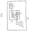
- FIG. 39 is a schematic diagram of an embodiment of a respiratory drug delivery apparatus 160 according to this aspect of the invention.
- the respiratory drug delivery apparatus 160 includes a housing 162 which houses a modified sound module 22' in which the sound circuit 26 directly receives power from the power source 30.
- the housing 162 also houses one or more sensors 164 which are provided for sensing or detecting the occurrence of the events that will trigger the generation of the particular audio instructions described above (for example, as shown in FIG. 39 , one or more of the sensors 164 may be operatively coupled to a valve such as an inhalation to sense opening and closing of the valve).
- the sound circuit 26 will select a data relating to an instruction or set of instructions from its internal memory that corresponds to the actuation signal, and will then drive the speaker 32 to cause it to generate the particular audible instruction or instructions based in the retrieved data.
- the instruction or set of instructions may relate to proper inhalation technique and/or proper breath hold technique.
- the sound module 22' requires no more than 3 volts to operate and the speaker 32 has a rating of no more than 8 ohms.
- the event that is sensed may be the actuation of the MDI by the patient.
- one or more of the sensors 164 may be used to sense the spray of medication within the main chamber housing 8 of a valved holding chamber 2 as shown herein.
- Those sensors 164 may constitute an optical sensor for optically sensing such a spray of medication, and may include a photo-emitter and a photo-detector for such purposes.
- one or more of the sensors 164 may be a pressure sensor or a flow sensor for sensing, for example, the spray of medication and/or the beginning and/or end of inhalation by sensing flow levels or open and closed states of an inhalation valve.
- respiratory drug delivery apparatus such as a valved holding chamber
- an airflow actuated noisemaker integrally formed therein (see FIG. 39 ).
- the noisemaker may be, for example, a whistle or, alternatively, a device including a sound reed which is caused to vibrate by air flowing thereover.
- the noisemaker may, for example, be a high airflow indicator that is structured to generate a noise when the air flowing through the respiratory drug delivery apparatus as a result of patient inhalation exceeds some predetermine level, in which case the noisemaker provides a cautionary indication to the patient that the patient is inhaling too quickly and should slow down.
- One of the sensors 164 may therefore comprise a microphone which will trigger the generation of an instruction instructing the patient to slow his or her breathing down when the noise from the noisemaker is sensed.
- the scenarios just described are merely exemplary, and it will be appreciated that other types of sensors 164 may be employed to detect the occurrence of various events of interest.
- the audio training device 184, 184' may be coupled to a jet nebulizer 182 rather than a valved holding chamber.
- FIG. 40 shows the audio training device 184 as a skirt which is slid down over the jet nebulizer 182.
- FIG. 41 shows the audio training devices 184' as a shell which is slid up onto the jet nebulizer 182.
- these audio trainer devices 184, 184' include a speaker 32 activated by button 186, 186'.
- this embodiment is manually activated through use of button 186, 186', audio training device 184, 184' may alternatively be activated by a sensor, not shown, as described above.
- an audio trainer 194 may be used with a dry powder inhaler 196.
- the dry powder inhaler 196 includes a mouthpiece 198 through which the dry powder is inhaled.
- the audio trainer 194 includes a speaker 32 activated by a button 200.
- the audio trainer 194 may be adhered to the dry powder inhaler 196.
- this embodiment is manually activated through use of button 200, audio training device 194 may alternatively be activated by a sensor, not shown, as described above.
- an audio trainer 204 may be used with an metered dose inhaler 206.
- the metered dose inhaler 206 includes a canister 208 fitted within a boot 210.
- the boot 210 terminates at a mouthpiece 212 through which aerosol is inhaled.
- the audio trainer 204 includes a speaker 32 activated by a button 214.
- the audio trainer 204 is slid over the boot 210.
- the audio trainer may be coupled to the canister 208.
- this embodiment is manually activated through use of button 214, audio training device 204 may alternatively be activated by a sensor, not shown, as described above.
- valved holding chamber 2 a jet nebulizer 182, a dry powder inhaler 196, and a metered dose inhaler (without a valved holding chamber)
- a respiratory drug apparatus of another type may also employ the concepts described herein.
- such devices will typically housing of some type for holding a source of a medication, to which the sound generator describe herein may be coupled, and a patient interface portion, such as a mouthpiece or the like, for delivering one or more doses of the medication to the patient's airway.
Landscapes
- Health & Medical Sciences (AREA)
- Engineering & Computer Science (AREA)
- Life Sciences & Earth Sciences (AREA)
- Animal Behavior & Ethology (AREA)
- Anesthesiology (AREA)
- Biomedical Technology (AREA)
- Heart & Thoracic Surgery (AREA)
- Hematology (AREA)
- Bioinformatics & Cheminformatics (AREA)
- Pulmonology (AREA)
- General Health & Medical Sciences (AREA)
- Public Health (AREA)
- Veterinary Medicine (AREA)
- Measurement Of The Respiration, Hearing Ability, Form, And Blood Characteristics Of Living Organisms (AREA)
- Pharmaceuticals Containing Other Organic And Inorganic Compounds (AREA)
- Instructional Devices (AREA)
- Percussion Or Vibration Massage (AREA)
- Medical Preparation Storing Or Oral Administration Devices (AREA)
Applications Claiming Priority (2)
| Application Number | Priority Date | Filing Date | Title |
|---|---|---|---|
| US9154608P | 2008-08-25 | 2008-08-25 | |
| PCT/IB2009/053604 WO2010023591A2 (en) | 2008-08-25 | 2009-08-15 | Respiratory drug delivery apparatus which provides audio instructions |
Publications (2)
| Publication Number | Publication Date |
|---|---|
| EP2318080A2 EP2318080A2 (en) | 2011-05-11 |
| EP2318080B1 true EP2318080B1 (en) | 2016-08-10 |
Family
ID=41351539
Family Applications (1)
| Application Number | Title | Priority Date | Filing Date |
|---|---|---|---|
| EP09786947.3A Active EP2318080B1 (en) | 2008-08-25 | 2009-08-15 | Respiratory drug delivery apparatus which provides audio instructions |
Country Status (7)
| Country | Link |
|---|---|
| US (1) | US9555202B2 (zh) |
| EP (1) | EP2318080B1 (zh) |
| JP (1) | JP5746625B2 (zh) |
| CN (1) | CN102159268B (zh) |
| AU (1) | AU2009286377A1 (zh) |
| BR (1) | BRPI0912918B8 (zh) |
| WO (1) | WO2010023591A2 (zh) |
Families Citing this family (63)
| Publication number | Priority date | Publication date | Assignee | Title |
|---|---|---|---|---|
| EP2037999B1 (en) | 2006-07-07 | 2016-12-28 | Proteus Digital Health, Inc. | Smart parenteral administration system |
| WO2009055733A1 (en) | 2007-10-25 | 2009-04-30 | Proteus Biomedical, Inc. | Fluid transfer port information system |
| US20110232636A1 (en) * | 2008-12-18 | 2011-09-29 | Koninklijke Philips Electronics, N.V. | Valved holding chamber and mask therefor |
| US20100169260A1 (en) * | 2008-12-30 | 2010-07-01 | Searete Llc | Methods and systems for presenting an inhalation experience |
| US20100163038A1 (en) * | 2008-12-30 | 2010-07-01 | Searete Llc, A Limited Liability Corporation Of The State Of Delaware | Methods and systems for presenting an inhalation experience |
| US20100168525A1 (en) * | 2008-12-30 | 2010-07-01 | Searete Llc, A Limited Liability Corporation Of The State Of Delaware | Methods and systems for presenting an inhalation experience |
| US20100169259A1 (en) * | 2008-12-30 | 2010-07-01 | Searete Llc, A Limited Liability Corporation Of The State Of Delaware | Methods and systems for presenting an inhalation experience |
| US20100163033A1 (en) * | 2008-12-30 | 2010-07-01 | Searete Llc, A Limited Liability Corporation Of The State Of Delaware | Methods and systems for presenting an inhalation experience |
| US8738395B2 (en) * | 2008-12-30 | 2014-05-27 | The Invention Science Fund I, Llc | Methods and systems for presenting an inhalation experience |
| US8694330B2 (en) * | 2008-12-30 | 2014-04-08 | The Invention Science Fund I, Llc | Methods and systems for presenting an inhalation experience |
| US20100168602A1 (en) * | 2008-12-30 | 2010-07-01 | Searete Llc | Methods and systems for presenting an inhalation experience |
| US20100163020A1 (en) * | 2008-12-30 | 2010-07-01 | Searete Llc, A Limited Liability Corporation Of The State Of Delaware | Method for administering an inhalable compound |
| US20100163036A1 (en) * | 2008-12-30 | 2010-07-01 | Searete Llc, A Limited Liability Corporation Of The State Of Delaware | Methods and systems for presenting an inhalation experience |
| US8725529B2 (en) * | 2008-12-30 | 2014-05-13 | The Invention Science Fund I, Llc | Methods and systems for presenting an inhalation experience |
| US8712794B2 (en) * | 2008-12-30 | 2014-04-29 | The Invention Science Fund I, Llc | Methods and systems for presenting an inhalation experience |
| US20100163034A1 (en) * | 2008-12-30 | 2010-07-01 | Searete Llc, A Limited Liability Corporation Of The State Of Delaware | Methods and systems for presenting an inhalation experience |
| US8706518B2 (en) * | 2008-12-30 | 2014-04-22 | The Invention Science Fund I, Llc | Methods and systems for presenting an inhalation experience |
| US20100163025A1 (en) * | 2008-12-30 | 2010-07-01 | Searete Llc | Methods and systems for presenting an inhalation experience |
| US20100168529A1 (en) * | 2008-12-30 | 2010-07-01 | Searete Llc, A Limited Liability Corporation Of The State Of Delaware | Methods and systems for presenting an inhalation experience |
| NZ574666A (en) * | 2009-02-05 | 2009-04-30 | Nexus6 Ltd | A medicament inhaler holder that uses optical means to count and display the number of doses used |
| US20130255678A1 (en) * | 2009-07-01 | 2013-10-03 | Microdose Therapeutx, Inc. | Nebulizer for infants and respiratory compromised patients |
| US9352107B2 (en) | 2010-01-07 | 2016-05-31 | Koninklijke Philips N.V. | Respiratory drug delivery apparatus including a feedback and compliance device |
| WO2011094608A2 (en) | 2010-02-01 | 2011-08-04 | Proteus Biomedical, Inc. | Two-wrist data gathering system |
| KR101798128B1 (ko) | 2010-02-01 | 2017-11-16 | 프로테우스 디지털 헬스, 인코포레이티드 | 데이터 수집 시스템 |
| US8438044B2 (en) | 2011-01-18 | 2013-05-07 | Audiahealth, Llc | Systems and methods combining print and audio technologies to deliver and personalize health information |
| US20140257126A1 (en) * | 2011-10-27 | 2014-09-11 | Koninklijke Philips N.V. | Systems and methods for combined respiratory therapy and respiratory monitoring |
| CA2859925C (en) | 2011-12-27 | 2019-02-19 | Vectura Gmbh | Inhalation device with feedback system |
| WO2014053242A1 (de) * | 2012-10-04 | 2014-04-10 | Boehringer Ingelheim International Gmbh | System, verfahren und verwendung zum trainieren eines inhalationsvorgangs |
| USD735316S1 (en) * | 2013-03-11 | 2015-07-28 | Fsc Laboratories, Inc. | Inhalation spacer |
| CN105163784B (zh) * | 2013-03-21 | 2019-07-26 | 皇家飞利浦有限公司 | 用于监控呼吸药物输送装置使用的系统和方法 |
| US10207065B2 (en) | 2013-07-12 | 2019-02-19 | John H. Silva | Mouthpiece for inhalers |
| CN105492057B (zh) * | 2013-08-30 | 2019-05-14 | 安瑞智能(新西兰)有限公司 | 用于药物吸入器的顺从性监视器 |
| CN104874061A (zh) * | 2014-02-28 | 2015-09-02 | 北京谊安医疗系统股份有限公司 | 呼吸机的喇叭状态的检测方法和检测装置 |
| EP3113817B1 (en) * | 2014-03-03 | 2020-10-28 | Adherium (NZ) Limited | A compliance monitor for a dry powder medicament delivery device |
| EP3116394A4 (en) * | 2014-03-10 | 2017-12-06 | respEQ Inc. | Systems and methods for delivering an agent to a user's lungs and for simultaneously monitoring lung health |
| JP6599890B2 (ja) * | 2014-04-07 | 2019-10-30 | ベーリンガー インゲルハイム インターナショナル ゲゼルシャフト ミット ベシュレンクテル ハフツング | 患者の吸入過程を訓練する吸入トレーニング装置及びシステム |
| EP3129087B1 (en) * | 2014-04-07 | 2020-02-26 | Boehringer Ingelheim International GmbH | Method, electronic device, inhalation training system for practicing and/or controlling an inhalation process of a patient |
| US11273271B2 (en) | 2014-07-01 | 2022-03-15 | Aerami Therapeutics, Inc. | Aerosolization system with flow restrictor and feedback device |
| US10471222B2 (en) | 2014-07-01 | 2019-11-12 | Dance Biopharm Inc. | Aerosolization system with flow restrictor and feedback device |
| US10857313B2 (en) | 2014-07-01 | 2020-12-08 | Aerami Therapeutics, Inc. | Liquid nebulization systems and methods |
| USD748242S1 (en) * | 2014-07-11 | 2016-01-26 | H. Stuart Campbell | Inhaler mouthpiece |
| ES2843262T3 (es) | 2014-08-28 | 2021-07-16 | Norton Waterford Ltd | Módulo de monitorización del cumplimiento de un inhalador |
| WO2016043601A1 (en) | 2014-09-15 | 2016-03-24 | Adherium (Nz) Ltd | Adherence monitor for a dry powder medicament delivery device |
| EP3247434B1 (en) * | 2015-01-22 | 2020-06-24 | Koninklijke Philips N.V. | Feature assigned inhalation aid |
| GB2537150A (en) * | 2015-04-09 | 2016-10-12 | Univ Manchester | Inhaler spacer |
| EP3416711B1 (en) * | 2016-02-17 | 2022-04-06 | Adherium (NZ) Limited | Adherence monitor for a medicament inhaler with tethered cap |
| JP7155010B2 (ja) | 2016-03-24 | 2022-10-18 | トゥルーデル メディカル インターナショナル | 電子インジケータを備えた呼吸治療システム |
| JP7231410B2 (ja) | 2016-04-12 | 2023-03-01 | バイオコープ プロダクション エス.アー. | 定量吸入器用アドオン装置、遵守向上システム、及び定量吸入器における使用の遵守向上のための方法 |
| CA3201693A1 (en) | 2016-05-19 | 2017-11-23 | Trudell Medical International | Smart valved holding chamber |
| DK3463248T3 (da) * | 2016-05-27 | 2022-10-31 | Proveris Scient Corporation | Anordnnger til anvendelse af lægemiddelanordninger |
| ES2894895T3 (es) | 2016-07-08 | 2022-02-16 | Trudell Medical Int | Dispositivo de presión espiratoria positiva oscilante inteligente |
| CA3036631A1 (en) | 2016-12-09 | 2018-06-14 | Trudell Medical International | Smart nebulizer |
| EP3554600B1 (en) | 2016-12-16 | 2020-07-29 | Koninklijke Philips N.V. | Training device for an inhaler, and an inhaler |
| USD835260S1 (en) * | 2017-04-06 | 2018-12-04 | Abithas, Llc | Delivery assist device for metered dose inhaler |
| MX2020007026A (es) | 2018-01-04 | 2020-12-03 | Trudell Medical Int | Dispositivo de presión espiratoria positiva oscilante inteligente. |
| TWM565606U (zh) * | 2018-04-11 | 2018-08-21 | 微邦科技股份有限公司 | Atomizing liquid container and its inlet and exhaust parts |
| CA3101434A1 (en) | 2018-06-04 | 2019-12-12 | Trudell Medical International | Smart valved holding chamber |
| US11577033B2 (en) | 2018-06-05 | 2023-02-14 | Medline Industries, Lp | Valved spacer for inhalation device |
| US11419995B2 (en) | 2019-04-30 | 2022-08-23 | Norton (Waterford) Limited | Inhaler system |
| AU2020278126A1 (en) | 2019-05-17 | 2021-12-16 | Norton (Waterford) Limited | Drug delivery device with electronics |
| US11432776B2 (en) | 2019-06-13 | 2022-09-06 | International Business Machines Corporation | Medical device administration and interaction |
| CA3152072A1 (en) | 2019-08-27 | 2021-03-04 | Trudell Medical International | Smart oscillating positive expiratory pressure device |
| US11749091B2 (en) * | 2021-07-09 | 2023-09-05 | Create To Overcome Llc | Electronic material sleeve for medical devices |
Family Cites Families (37)
| Publication number | Priority date | Publication date | Assignee | Title |
|---|---|---|---|---|
| US4484577A (en) * | 1981-07-23 | 1984-11-27 | Key Pharmaceuticals, Inc. | Drug delivery method and inhalation device therefor |
| US4470412A (en) | 1982-03-19 | 1984-09-11 | Trutek Research, Inc. | Inhalation valve |
| US4809692A (en) * | 1986-01-31 | 1989-03-07 | Trudell Medical | Pediatric asthmatic medication inhaler |
| US4832015A (en) * | 1988-05-19 | 1989-05-23 | Trudell Medical | Pediatric asthmatic inhaler |
| US4984158A (en) * | 1988-10-14 | 1991-01-08 | Hillsman Dean | Metered dose inhaler biofeedback training and evaluation system |
| GB2225474A (en) * | 1988-12-01 | 1990-05-30 | To Ping Kuan | Musical attachment for nursing bottle or other liquid container |
| US5012803A (en) | 1989-03-06 | 1991-05-07 | Trudell Medical | Modular medication inhaler |
| SE466684B (sv) * | 1989-03-07 | 1992-03-23 | Draco Ab | Anordning vid en inhalator samt foerfarande foer att med anordningen registrera medicinering med inhalator |
| US5042467A (en) * | 1990-03-28 | 1991-08-27 | Trudell Medical | Medication inhaler with fitting having a sonic signalling device |
| AU651882B2 (en) | 1991-05-14 | 1994-08-04 | Visiomed Group Limited | Aerosol inhalation device |
| US5363842A (en) * | 1991-12-20 | 1994-11-15 | Circadian, Inc. | Intelligent inhaler providing feedback to both patient and medical professional |
| EP0667168B1 (en) | 1994-02-14 | 2000-06-21 | Aradigm Corporation | An inhalation training device |
| US5809997A (en) * | 1995-05-18 | 1998-09-22 | Medtrac Technologies, Inc. | Electronic medication chronolog device |
| US6359987B1 (en) * | 1997-05-16 | 2002-03-19 | Compaq Computer Corporation | Multimedia speaker detection circuit |
| US5905618A (en) * | 1997-07-07 | 1999-05-18 | International Business Machines Corporation | Voltage protected level shifting of chip driver |
| US5848599A (en) * | 1997-07-28 | 1998-12-15 | Todd; Mark D. | Apparatus for crimping and tattooing hair |
| US6293279B1 (en) | 1997-09-26 | 2001-09-25 | Trudell Medical International | Aerosol medication delivery apparatus and system |
| US6358058B1 (en) * | 1998-01-30 | 2002-03-19 | 1263152 Ontario Inc. | Aerosol dispensing inhaler training device |
| US6202642B1 (en) * | 1999-04-23 | 2001-03-20 | Medtrac Technologies, Inc. | Electronic monitoring medication apparatus and method |
| US6190326B1 (en) * | 1999-04-23 | 2001-02-20 | Medtrac Technologies, Inc. | Method and apparatus for obtaining patient respiratory data |
| US6240917B1 (en) * | 1999-12-20 | 2001-06-05 | Joseph R. Andrade | Aerosol holding chamber for a metered-dose inhaler |
| CA2826724C (en) * | 2000-04-11 | 2016-02-02 | Trudell Medical International | Aerosol delivery apparatus with positive expiratory pressure capacity |
| US7204245B2 (en) | 2000-07-06 | 2007-04-17 | Clinical Technologies, Inc | Aerosol enhancement device |
| US6523536B2 (en) * | 2001-03-12 | 2003-02-25 | Birdsong Medical Devices, Inc. | Dual-canister inhaler having a spacer and easy to operate lever mechanism |
| US20050022806A1 (en) * | 2001-06-11 | 2005-02-03 | Beaumont Gary Robert | Medicament dispenser |
| IL160628A0 (en) * | 2001-09-06 | 2004-07-25 | Microdose Technologies Inc | Adaptors for inhalers to improve performance |
| DK1495746T3 (da) * | 2002-03-07 | 2007-10-01 | Bang & Olufsen Medicom As | En medicinsk dispenser, et blisterkort til anvendelse i dispenseren og en metode til dispensering af medicindoser |
| WO2003092576A2 (en) | 2002-04-29 | 2003-11-13 | Glaxo Group Limited | Alerting system |
| JP2004195191A (ja) | 2002-10-22 | 2004-07-15 | Akihiko Miyamoto | 呼子付喘息治療薬吸入器 |
| GB2395437C (en) * | 2002-11-20 | 2010-10-20 | Profile Respiratory Systems Ltd | Improved inhalation method and apparatus |
| CN1925887B (zh) * | 2004-02-24 | 2010-12-22 | 微计量治疗公司 | 方向流传感器吸入器 |
| WO2005079997A1 (de) * | 2004-02-24 | 2005-09-01 | Boehringer Ingelheim International Gmbh | Zerstäuber |
| DE102004009435A1 (de) * | 2004-02-24 | 2005-12-08 | Boehringer Ingelheim International Gmbh | Zerstäuber |
| US20060130838A1 (en) * | 2004-12-20 | 2006-06-22 | Lee Yong Y | Data logger for monitoring asthmatic conditions |
| ES2396745T3 (es) * | 2005-02-01 | 2013-02-25 | Intelliject, Inc. | Disposirtivos para administración de medicamentos |
| JP4789567B2 (ja) | 2005-10-04 | 2011-10-12 | キヤノン株式会社 | 液体吐出装置 |
| EP2125075A2 (en) | 2007-01-22 | 2009-12-02 | Intelliject, Inc. | Medical injector with compliance tracking and monitoring |
-
2009
- 2009-08-15 EP EP09786947.3A patent/EP2318080B1/en active Active
- 2009-08-15 WO PCT/IB2009/053604 patent/WO2010023591A2/en active Application Filing
- 2009-08-15 US US13/060,319 patent/US9555202B2/en active Active
- 2009-08-15 CN CN200980132986.5A patent/CN102159268B/zh active Active
- 2009-08-15 JP JP2011524486A patent/JP5746625B2/ja active Active
- 2009-08-15 AU AU2009286377A patent/AU2009286377A1/en not_active Abandoned
- 2009-08-15 BR BRPI0912918A patent/BRPI0912918B8/pt active IP Right Grant
Also Published As
| Publication number | Publication date |
|---|---|
| JP2012500702A (ja) | 2012-01-12 |
| BRPI0912918B1 (pt) | 2019-09-17 |
| WO2010023591A3 (en) | 2010-04-22 |
| AU2009286377A1 (en) | 2010-03-04 |
| JP5746625B2 (ja) | 2015-07-08 |
| CN102159268B (zh) | 2015-06-17 |
| US20110226242A1 (en) | 2011-09-22 |
| WO2010023591A2 (en) | 2010-03-04 |
| CN102159268A (zh) | 2011-08-17 |
| EP2318080A2 (en) | 2011-05-11 |
| US9555202B2 (en) | 2017-01-31 |
| BRPI0912918B8 (pt) | 2021-06-22 |
| BRPI0912918A2 (pt) | 2016-07-05 |
Similar Documents
| Publication | Publication Date | Title |
|---|---|---|
| EP2318080B1 (en) | Respiratory drug delivery apparatus which provides audio instructions | |
| EP2521583B1 (en) | A feedback and compliance device for an inhaler | |
| US6718969B1 (en) | Medication dosage inhaler system | |
| US4291688A (en) | Inhalation device | |
| US6260549B1 (en) | Breath-activated metered-dose inhaler | |
| EP3117858B1 (en) | Nebulizer for infants and respiratory compromised patients | |
| US20020104531A1 (en) | Pediatric inhalation device | |
| JP5919277B2 (ja) | バルブ保有システムを含むバルブ付き保持チャンバ | |
| US20050133024A1 (en) | Devices for measuring inspiratory airflow | |
| GB2306891A (en) | Combined inhaler and spirometer | |
| EP1407794B1 (en) | Asthma drug inhaler with whistle | |
| EP0014814A1 (en) | Inhalation device and sounding device for it | |
| EP1747791B1 (en) | Asthma preparation inhaler auxiliary device with reed | |
| US11577033B2 (en) | Valved spacer for inhalation device | |
| CN210844740U (zh) | 一种智能口鼻气雾剂给药装置 | |
| AU2013209385B2 (en) | Nebulizer for infants and respiratory compromised patients | |
| KR20230133993A (ko) | 구강 위생용 에어로졸 흡입기 | |
| WO2021234432A1 (en) | Meted dose inhalers (mdi's) efficiency increasing system (shafadam) |
Legal Events
| Date | Code | Title | Description |
|---|---|---|---|
| PUAI | Public reference made under article 153(3) epc to a published international application that has entered the european phase |
Free format text: ORIGINAL CODE: 0009012 |
|
| 17P | Request for examination filed |
Effective date: 20110325 |
|
| AK | Designated contracting states |
Kind code of ref document: A2 Designated state(s): AT BE BG CH CY CZ DE DK EE ES FI FR GB GR HR HU IE IS IT LI LT LU LV MC MK MT NL NO PL PT RO SE SI SK SM TR |
|
| AX | Request for extension of the european patent |
Extension state: AL BA RS |
|
| DAX | Request for extension of the european patent (deleted) | ||
| RAP1 | Party data changed (applicant data changed or rights of an application transferred) |
Owner name: KONINKLIJKE PHILIPS N.V. |
|
| GRAP | Despatch of communication of intention to grant a patent |
Free format text: ORIGINAL CODE: EPIDOSNIGR1 |
|
| INTG | Intention to grant announced |
Effective date: 20160225 |
|
| GRAS | Grant fee paid |
Free format text: ORIGINAL CODE: EPIDOSNIGR3 |
|
| GRAA | (expected) grant |
Free format text: ORIGINAL CODE: 0009210 |
|
| AK | Designated contracting states |
Kind code of ref document: B1 Designated state(s): AT BE BG CH CY CZ DE DK EE ES FI FR GB GR HR HU IE IS IT LI LT LU LV MC MK MT NL NO PL PT RO SE SI SK SM TR |
|
| REG | Reference to a national code |
Ref country code: GB Ref legal event code: FG4D |
|
| REG | Reference to a national code |
Ref country code: CH Ref legal event code: EP Ref country code: AT Ref legal event code: REF Ref document number: 818416 Country of ref document: AT Kind code of ref document: T Effective date: 20160815 |
|
| REG | Reference to a national code |
Ref country code: FR Ref legal event code: PLFP Year of fee payment: 8 |
|
| REG | Reference to a national code |
Ref country code: IE Ref legal event code: FG4D |
|
| REG | Reference to a national code |
Ref country code: DE Ref legal event code: R096 Ref document number: 602009040304 Country of ref document: DE |
|
| REG | Reference to a national code |
Ref country code: LT Ref legal event code: MG4D |
|
| REG | Reference to a national code |
Ref country code: NL Ref legal event code: MP Effective date: 20160810 |
|
| REG | Reference to a national code |
Ref country code: AT Ref legal event code: MK05 Ref document number: 818416 Country of ref document: AT Kind code of ref document: T Effective date: 20160810 |
|
| PG25 | Lapsed in a contracting state [announced via postgrant information from national office to epo] |
Ref country code: NL Free format text: LAPSE BECAUSE OF FAILURE TO SUBMIT A TRANSLATION OF THE DESCRIPTION OR TO PAY THE FEE WITHIN THE PRESCRIBED TIME-LIMIT Effective date: 20160810 Ref country code: LT Free format text: LAPSE BECAUSE OF FAILURE TO SUBMIT A TRANSLATION OF THE DESCRIPTION OR TO PAY THE FEE WITHIN THE PRESCRIBED TIME-LIMIT Effective date: 20160810 Ref country code: IT Free format text: LAPSE BECAUSE OF FAILURE TO SUBMIT A TRANSLATION OF THE DESCRIPTION OR TO PAY THE FEE WITHIN THE PRESCRIBED TIME-LIMIT Effective date: 20160810 Ref country code: FI Free format text: LAPSE BECAUSE OF FAILURE TO SUBMIT A TRANSLATION OF THE DESCRIPTION OR TO PAY THE FEE WITHIN THE PRESCRIBED TIME-LIMIT Effective date: 20160810 Ref country code: IS Free format text: LAPSE BECAUSE OF FAILURE TO SUBMIT A TRANSLATION OF THE DESCRIPTION OR TO PAY THE FEE WITHIN THE PRESCRIBED TIME-LIMIT Effective date: 20161210 Ref country code: NO Free format text: LAPSE BECAUSE OF FAILURE TO SUBMIT A TRANSLATION OF THE DESCRIPTION OR TO PAY THE FEE WITHIN THE PRESCRIBED TIME-LIMIT Effective date: 20161110 Ref country code: HR Free format text: LAPSE BECAUSE OF FAILURE TO SUBMIT A TRANSLATION OF THE DESCRIPTION OR TO PAY THE FEE WITHIN THE PRESCRIBED TIME-LIMIT Effective date: 20160810 |
|
| PG25 | Lapsed in a contracting state [announced via postgrant information from national office to epo] |
Ref country code: AT Free format text: LAPSE BECAUSE OF FAILURE TO SUBMIT A TRANSLATION OF THE DESCRIPTION OR TO PAY THE FEE WITHIN THE PRESCRIBED TIME-LIMIT Effective date: 20160810 Ref country code: ES Free format text: LAPSE BECAUSE OF FAILURE TO SUBMIT A TRANSLATION OF THE DESCRIPTION OR TO PAY THE FEE WITHIN THE PRESCRIBED TIME-LIMIT Effective date: 20160810 Ref country code: GR Free format text: LAPSE BECAUSE OF FAILURE TO SUBMIT A TRANSLATION OF THE DESCRIPTION OR TO PAY THE FEE WITHIN THE PRESCRIBED TIME-LIMIT Effective date: 20161111 Ref country code: SE Free format text: LAPSE BECAUSE OF FAILURE TO SUBMIT A TRANSLATION OF THE DESCRIPTION OR TO PAY THE FEE WITHIN THE PRESCRIBED TIME-LIMIT Effective date: 20160810 Ref country code: PT Free format text: LAPSE BECAUSE OF FAILURE TO SUBMIT A TRANSLATION OF THE DESCRIPTION OR TO PAY THE FEE WITHIN THE PRESCRIBED TIME-LIMIT Effective date: 20161212 Ref country code: PL Free format text: LAPSE BECAUSE OF FAILURE TO SUBMIT A TRANSLATION OF THE DESCRIPTION OR TO PAY THE FEE WITHIN THE PRESCRIBED TIME-LIMIT Effective date: 20160810 Ref country code: LV Free format text: LAPSE BECAUSE OF FAILURE TO SUBMIT A TRANSLATION OF THE DESCRIPTION OR TO PAY THE FEE WITHIN THE PRESCRIBED TIME-LIMIT Effective date: 20160810 Ref country code: BE Free format text: LAPSE BECAUSE OF NON-PAYMENT OF DUE FEES Effective date: 20160831 |
|
| REG | Reference to a national code |
Ref country code: CH Ref legal event code: PL |
|
| PG25 | Lapsed in a contracting state [announced via postgrant information from national office to epo] |
Ref country code: LI Free format text: LAPSE BECAUSE OF NON-PAYMENT OF DUE FEES Effective date: 20160831 Ref country code: RO Free format text: LAPSE BECAUSE OF FAILURE TO SUBMIT A TRANSLATION OF THE DESCRIPTION OR TO PAY THE FEE WITHIN THE PRESCRIBED TIME-LIMIT Effective date: 20160810 Ref country code: CH Free format text: LAPSE BECAUSE OF NON-PAYMENT OF DUE FEES Effective date: 20160831 Ref country code: EE Free format text: LAPSE BECAUSE OF FAILURE TO SUBMIT A TRANSLATION OF THE DESCRIPTION OR TO PAY THE FEE WITHIN THE PRESCRIBED TIME-LIMIT Effective date: 20160810 |
|
| REG | Reference to a national code |
Ref country code: DE Ref legal event code: R097 Ref document number: 602009040304 Country of ref document: DE |
|
| PG25 | Lapsed in a contracting state [announced via postgrant information from national office to epo] |
Ref country code: SK Free format text: LAPSE BECAUSE OF FAILURE TO SUBMIT A TRANSLATION OF THE DESCRIPTION OR TO PAY THE FEE WITHIN THE PRESCRIBED TIME-LIMIT Effective date: 20160810 Ref country code: BE Free format text: LAPSE BECAUSE OF FAILURE TO SUBMIT A TRANSLATION OF THE DESCRIPTION OR TO PAY THE FEE WITHIN THE PRESCRIBED TIME-LIMIT Effective date: 20160810 Ref country code: SM Free format text: LAPSE BECAUSE OF FAILURE TO SUBMIT A TRANSLATION OF THE DESCRIPTION OR TO PAY THE FEE WITHIN THE PRESCRIBED TIME-LIMIT Effective date: 20160810 Ref country code: BG Free format text: LAPSE BECAUSE OF FAILURE TO SUBMIT A TRANSLATION OF THE DESCRIPTION OR TO PAY THE FEE WITHIN THE PRESCRIBED TIME-LIMIT Effective date: 20161110 Ref country code: DK Free format text: LAPSE BECAUSE OF FAILURE TO SUBMIT A TRANSLATION OF THE DESCRIPTION OR TO PAY THE FEE WITHIN THE PRESCRIBED TIME-LIMIT Effective date: 20160810 Ref country code: CZ Free format text: LAPSE BECAUSE OF FAILURE TO SUBMIT A TRANSLATION OF THE DESCRIPTION OR TO PAY THE FEE WITHIN THE PRESCRIBED TIME-LIMIT Effective date: 20160810 |
|
| REG | Reference to a national code |
Ref country code: IE Ref legal event code: MM4A |
|
| PLBE | No opposition filed within time limit |
Free format text: ORIGINAL CODE: 0009261 |
|
| STAA | Information on the status of an ep patent application or granted ep patent |
Free format text: STATUS: NO OPPOSITION FILED WITHIN TIME LIMIT |
|
| PG25 | Lapsed in a contracting state [announced via postgrant information from national office to epo] |
Ref country code: MC Free format text: LAPSE BECAUSE OF FAILURE TO SUBMIT A TRANSLATION OF THE DESCRIPTION OR TO PAY THE FEE WITHIN THE PRESCRIBED TIME-LIMIT Effective date: 20160810 |
|
| 26N | No opposition filed |
Effective date: 20170511 |
|
| PG25 | Lapsed in a contracting state [announced via postgrant information from national office to epo] |
Ref country code: IE Free format text: LAPSE BECAUSE OF NON-PAYMENT OF DUE FEES Effective date: 20160815 |
|
| REG | Reference to a national code |
Ref country code: FR Ref legal event code: PLFP Year of fee payment: 9 |
|
| PG25 | Lapsed in a contracting state [announced via postgrant information from national office to epo] |
Ref country code: SI Free format text: LAPSE BECAUSE OF FAILURE TO SUBMIT A TRANSLATION OF THE DESCRIPTION OR TO PAY THE FEE WITHIN THE PRESCRIBED TIME-LIMIT Effective date: 20160810 Ref country code: LU Free format text: LAPSE BECAUSE OF NON-PAYMENT OF DUE FEES Effective date: 20160815 |
|
| PG25 | Lapsed in a contracting state [announced via postgrant information from national office to epo] |
Ref country code: CY Free format text: LAPSE BECAUSE OF FAILURE TO SUBMIT A TRANSLATION OF THE DESCRIPTION OR TO PAY THE FEE WITHIN THE PRESCRIBED TIME-LIMIT Effective date: 20160810 Ref country code: HU Free format text: LAPSE BECAUSE OF FAILURE TO SUBMIT A TRANSLATION OF THE DESCRIPTION OR TO PAY THE FEE WITHIN THE PRESCRIBED TIME-LIMIT; INVALID AB INITIO Effective date: 20090815 |
|
| PG25 | Lapsed in a contracting state [announced via postgrant information from national office to epo] |
Ref country code: TR Free format text: LAPSE BECAUSE OF FAILURE TO SUBMIT A TRANSLATION OF THE DESCRIPTION OR TO PAY THE FEE WITHIN THE PRESCRIBED TIME-LIMIT Effective date: 20160810 Ref country code: MK Free format text: LAPSE BECAUSE OF FAILURE TO SUBMIT A TRANSLATION OF THE DESCRIPTION OR TO PAY THE FEE WITHIN THE PRESCRIBED TIME-LIMIT Effective date: 20160810 Ref country code: MT Free format text: LAPSE BECAUSE OF NON-PAYMENT OF DUE FEES Effective date: 20160831 |
|
| REG | Reference to a national code |
Ref country code: FR Ref legal event code: PLFP Year of fee payment: 10 |
|
| PGFP | Annual fee paid to national office [announced via postgrant information from national office to epo] |
Ref country code: GB Payment date: 20230822 Year of fee payment: 15 |
|
| PGFP | Annual fee paid to national office [announced via postgrant information from national office to epo] |
Ref country code: FR Payment date: 20230824 Year of fee payment: 15 Ref country code: DE Payment date: 20230828 Year of fee payment: 15 |