EP2317279A1 - Method and device for measuring thickness of multilayer film - Google Patents
Method and device for measuring thickness of multilayer film Download PDFInfo
- Publication number
- EP2317279A1 EP2317279A1 EP10189336A EP10189336A EP2317279A1 EP 2317279 A1 EP2317279 A1 EP 2317279A1 EP 10189336 A EP10189336 A EP 10189336A EP 10189336 A EP10189336 A EP 10189336A EP 2317279 A1 EP2317279 A1 EP 2317279A1
- Authority
- EP
- European Patent Office
- Prior art keywords
- optical thickness
- thickness
- multilayer film
- optical
- layers
- Prior art date
- Legal status (The legal status is an assumption and is not a legal conclusion. Google has not performed a legal analysis and makes no representation as to the accuracy of the status listed.)
- Withdrawn
Links
Images
Classifications
-
- G—PHYSICS
- G01—MEASURING; TESTING
- G01B—MEASURING LENGTH, THICKNESS OR SIMILAR LINEAR DIMENSIONS; MEASURING ANGLES; MEASURING AREAS; MEASURING IRREGULARITIES OF SURFACES OR CONTOURS
- G01B11/00—Measuring arrangements characterised by the use of optical techniques
- G01B11/02—Measuring arrangements characterised by the use of optical techniques for measuring length, width or thickness
- G01B11/06—Measuring arrangements characterised by the use of optical techniques for measuring length, width or thickness for measuring thickness ; e.g. of sheet material
- G01B11/0616—Measuring arrangements characterised by the use of optical techniques for measuring length, width or thickness for measuring thickness ; e.g. of sheet material of coating
- G01B11/0625—Measuring arrangements characterised by the use of optical techniques for measuring length, width or thickness for measuring thickness ; e.g. of sheet material of coating with measurement of absorption or reflection
Definitions
- the present disclosure relates to a method and device capable of measuring the thicknesses of various kinds of multilayer films.
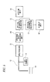
- Fig. 5 shows the structure of a film thickness meter that measures the thickness of a multilayer film.
- white light emitted from a light source 11 is provided to a multilayer film 10 through an optical fiber 12.
- the light reflected by the multilayer film 10 is guided to a spectroscope 13 through the optical fiber 12.
- the spectroscope 13 disperses the reflected light, converts the dispersed light into an electric signal, and generates a spectrum.
- the spectrum is acquired by a spectral data acquiring unit 14 and is then output to an optical thickness calculator 15.
- a setting unit 16 sets a wavelength band for measuring the optical thickness and a peak detection range for detecting the peak of a power spectrum.
- the optical thickness calculator 15 measures the interference fringes and calculates the optical thickness.
- a reflectance spectrum is converted into a wavenumber domain reflectance spectrum in which the wavelength is arranged at equal intervals. Then, Fourier transform is performed on the data of the wavenumber domain reflectance spectrum to calculate the power spectrum in the set wavelength band. The peak of the power spectrum is detected in the peak detection range set by the setting unit 16. The optical thickness is obtained from the position of the peak.
- the optical thickness calculated by the optical thickness calculator 15 is input to a physical thickness calculator 17.
- the physical thickness calculator 17 calculates the physical thickness, which is the actual film thickness, of each layer of the multilayer film 10, based on the optical thickness and the refractive index.
- the physical thickness is displayed on a display unit 18.
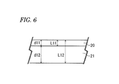
- Fig. 6 is a cross-sectional view illustrating the multilayer film.
- the multilayer film includes two layers 20 and 21, and the physical thicknesses of the two layers 20 and 21 are d11 and d12, respectively.
- the layer 21 is a film and the layer 20 is a coating layer formed on the film 21.
- the physical thicknesses d11 and d12 of the layers 20 and 21 are 1 ⁇ m and 150 ⁇ m, respectively.
- the optical thickness obtained from the light reflected by the boundary surface between the layers 20 and 21 is L11 and the optical thickness obtained from the light reflected by the rear surface of the multilayer film is L12.
- the optical thickness L11 relates to only the layer 20, but the optical thickness L12 relates to both the layer 20 and the layer 21.
- the optical thicknesses corresponding to the number of combinations of the boundary surfaces of the multilayer film.
- the optical thickness that can be actually measured depends on the reflectance or flatness of each boundary surface, it is not necessarily possible to directly detect the optical thickness of the desired layer.
- the optical thickness is the product of the physical thickness and the refractive index. Therefore, when the optical thickness of the desired layer can be directly measured, it is possible to calculate the physical thickness with a simple operation. However, when it is difficult to directly measure the optical thickness of the desired layer, an expression for obtaining the physical thickness needs to be derived from a combination of the optical thicknesses of a plurality of layers.
- JP-A-2008-292473 discloses an example in which the optical thickness is measured in a plurality of wavelength ranges using the relationship between the wavelength and the refractive index depending on the wavelength, which makes it possible to independently measure the physical thickness of each layer even though a plurality of layers have the same film thickness.
- the above-mentioned example will be now described with reference to the multilayer film shown in Fig. 6 .
- d11and d12 are the physical thicknesses
- L11 and L12 are the optical thicknesses.
- the optical thickness L12 relates to both the layer 20 and the layer 21. Therefore, d11 needs to be calculated by Expression (1) and d11 needs to be substituted into Expression (2) to calculate d12.
- the film thickness meter has the following problems.
- Expressions (1) and (2) depend on the optical thickness that can be measured or the structure of the multilayer film to be measured.
- Exemplary embodiments of the present invention address the above disadvantages and other disadvantages not described above.
- the present invention is not required to overcome the disadvantages described above, and thus, an exemplary embodiment of the present invention may not overcome any disadvantages
- a method of measuring a physical thickness of each of layers of a multilayer film, based on an optical thickness thereof includes: (a) setting refractive indexes of the layers; (b) calculating a coefficient matrix using the refractive indexes; (c) providing light to the multilayer film so as to measure the optical thickness based on the light reflected by the multilayer film; and (d) calculating the physical thickness, based on the optical thickness and the coefficient matrix.
- a device that measures a physical thickness of each of layers of a multilayer film, based on an optical thickness thereof.
- the device includes: an optical thickness measuring unit configured to provide light to the multilayer film so as to measure the optical thickness based on the light reflected by the multilayer film; a refractive index setting unit configured to set refractive indexes of the layers; a coefficient matrix calculator configured to calculate a coefficient matrix using the refractive indexes; and a physical thickness calculator configured to calculate the physical thickness based on the optical thickness and the coefficient matrix.
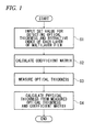
- Fig. 1 is a flowchart illustrating a method of measuring the thickness of a multilayer film according to an embodiment of the invention.
- a preliminary measuring process is performed to determine an optical thickness to be measured.
- the number of optical thicknesses to be measured is equal to the number of layers of the multilayer film.
- step S1 a set value for detecting the optical thickness and the refractive index of each layer of the multilayer film are input.
- the input of the set value and the refractive index will be described below.
- step S2 the input refractive index is used to calculate a coefficient matrix for calculating a physical thickness from the optical thickness.
- the coefficient matrix is used to calculate the physical thickness from the optical thickness.
- step S3 the optical thickness is measured by the same method as that in the related art. That is, white light is provided to the multilayer film, and light reflected by the multilayer film is dispersed to obtain a spectrum. The spectrum is converted into a wavenumber domain reflectance spectrum in which the wavelength is arranged at equal intervals, and Fourier transform is performed on the data of the wavenumber domain reflectance spectrum to calculate the power spectrum in the set wavelength band. Then, the peak of the power spectrum is detected in the peak detection range input in the step S1, and the optical thickness is calculated from the position of the peak.
- step S4 the physical thickness is calculated from the measured optical thickness and the coefficient matrix calculated in the step S2.
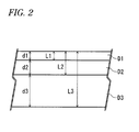
- Fig. 2 is a cross-sectional view illustrating the multilayer film to be measured.
- D1 to D3 are respective layers forming the multilayer film
- d1 to d3 are the respective physical thicknesses of the layers D1 to D3.
- the multilayer film includes three layers D1 to D3.
- the layers D1 to D3 are, for example, plastic films or coating layers on the film.
- the optical thickness L1 to L3 are the measured optical thicknesses.
- the optical thickness L1 is obtained by measuring interference fringes generated by the interference between light reflected from a front surface of the multilayer film and light reflected from the boundary surface between the layers D1 and D2.
- the optical thickness L2 is obtained by measuring interference fringes generated by the interference between the light reflected from the front surface of the multilayer film and light reflected from the boundary surface between D2 and D3.
- the optical thickness L3 is obtained by measuring interference fringes generated by the interference between the light reflected from the front surface of the multilayer film and light reflected from a rear surface of the multilayer film.
- the optical thickness L1 relates to only the layer D1, and the optical thickness L2 relates to the layers D1 and D2.
- the optical thickness L3 relates to all of the layers D1 to D3.
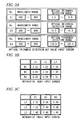
- Figs. 3A to 3C show input screens for data that is input in the step S1.
- Fig. 3A shows a set value input screen for detecting the optical thickness.
- Figs. 3B and 3C show a refractive index input screen.
- a wavelength range (left side) for measuring the optical thickness and an optical thickness search range (right side) for searching for the peak of the power spectrum are input for each of the optical thicknesses L1 to L3.
- the wavelength range of the optical thicknesses L1 and L2 is set in a range of 500 nm to 900 nm
- the wavelength range of the optical thickness L3 is set in a range of 800 nm to 900 nm. Since the refractive indexes of the layers D1 to D3 depend on the optical thicknesses, the wavelength range of the optical thickness L3 is different from that of the other optical thicknesses.
- the optical thickness search ranges are set in a range of 3.0 to 5.0, 10.0 to 15.0, and 110.0 to 120.0 for the optical thicknesses L1 to L3, respectively.
- the wavelength range and the optical thickness search range are set for each multilayer film such that the optical thickness can be accurately measured.
- the entire range may be a target range without setting the wavelength range and the optical thickness search range.
- Fig. 3B shows a screen for inputting the refractive indexes of the layers D1 to D3. Rows D1 to D3 correspond to the layers D1 and D3 and columns L1 to L3 correspond to the optical thicknesses L1 to L3, respectively.
- the refractive index in the wavelength range set in the optical thickness detection value input screen shown in Fig. 3A is input to an input field at the intersection between the row and the column.
- the refractive index of the layer that does not relate to each optical thickness is zero. In this way, the sensitivity of each optical thickness with respect to each layer is set.
- the refractive index, 1.52 of the layer D1 at a wavelength of 500 nm to 900 nm is input to the input field at the intersection between D1 and L 1, and 0.00 is input to the input fields at the intersections between D2 and D3, and L1.
- the optical thickness L2 relates to the layers D1 and D2, but does not relate to the layer D3. Therefore, 1.52 (which is equal to the value input to the input field at the intersection between D1 and L1) is input to the input field at the intersection between D1and L2, and the refractive index, 1.42, of the layer D2 at a wavelength of 500 nm to 900 nm is input to the input field at the intersection between D2 and L2. 0.00 is input to the input field at the intersection between D3 and L2.
- the optical thickness L3 relates to all of the layers D1 to D3.
- the refractive indexes, 1.48, 1.40, and 1.61, of the layers D1 to D3 at a wavelength of 800 nm to 900 nm are input to the input fields at the intersections between L3 and D1 to D3, respectively.
- the inverse matrix n -1 is a coefficient matrix for calculating the physical thickness from the optical thickness.
- the matrix of the refractive index is transposed.
- An inverse matrix of the matrix n may be calculated using an input value as the matrix n.
- the refractive index is not necessarily input using the screen shown in Fig. 3B or 3C .
- the refractive index of the layer related to each optical thickness and the refractive index of each layer in the set wavelength range may be input to generate the matrix n represented by Expression (6).
- L ⁇ L ⁇ 11
- Expression (10) is obtained as follows, and it is possible to calculate the physical thicknesses d11 and d12 from the optical thicknesses L11 and L12 and the refractive indexes n11 and n22.
- ⁇ 11, ..., ⁇ NN are the refractive indexes of each layer and are input by the method described in Figs. 3B and 3C .
- ⁇ ij is the refractive index of a layer j related to an optical thickness i.
- Expression (11) can be rearranged into the following Expression (12).
- L ⁇ 1 L ⁇ 2 ⁇ LN ⁇ ⁇ 11 ⁇ ⁇ 12 ... ⁇ ⁇ 1 ⁇ N ⁇ ⁇ 21 ⁇ ⁇ 22 ... ⁇ ⁇ 2 ⁇ N ⁇ ⁇ ⁇ ⁇ ⁇ N ⁇ 1 ⁇ N ⁇ 2 ... ⁇ NN ⁇ d ⁇ 1 d ⁇ 2 ⁇ dN
- Expression (12) may be transformed into the following Expression (13), and it is possible to calculate the physical thicknesses d1, d2, ..., dN from the optical thicknesses L1, L2, ..., LN.
- the matrix [ ⁇ ij] is a coefficient matrix for calculating the physical thickness from the optical thickness.
- the layers of the multilayer film it is possible to calculate the physical thickness of each layer from the optical thickness only by inputting the refractive index of each layer in the set wavelength range. Therefore, it is not necessary to know in advance the relationship between the optical thickness and the physical thickness of each layer. As a result, even when a new multilayer film is measured, it is not necessary to input the relational expression between the optical thickness and the physical thickness and modify the film thickness measuring device.
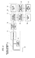
- Fig. 4 is a diagram illustrating a device for measuring the thickness of a multilayer film according to the embodiment.
- the same components as those in Fig. 5 are denoted by the same reference numerals and a description thereof will be omitted herein.
- the device includes an optical thickness measuring unit 30, a refractive index setting unit 31, a coefficient matrix calculator 32, a physical thickness calculator 33, and a display unit 34.
- the optical thickness measuring unit 30 includes a light source 11, an optical fiber 12, a spectroscope 13, a spectral data acquiring unit 14, an optical thickness calculator 15, and a setting unit 16.
- White light emitted from the light source 11 is guided to the optical fiber 12 and is provided to the multilayer film 10.
- Light reflected by the multilayer film 10 is provided to the spectroscope 13 through the optical fiber 12.
- the spectroscope 13 generates a spectrum of the reflected light.
- the spectrum is acquired by the spectrum data acquiring unit 14 and is then output to the optical thickness calculator 15.
- the setting unit 16 displays the screen shown in Fig. 3A on the display unit 34.
- the user uses the screen to set a wavelength range for measuring the optical thickness of each layer of the multilayer film and a power spectrum peak search range.
- the set values are input to the optical thickness calculator 15.
- the optical thickness calculator 15 calculates the optical thickness from the input spectrum and set values.
- the optical thickness calculator 15 converts the spectrum into the wavenumber domain reflectance spectrum in which the wavelength is arranged at equal intervals and performs Fourier transform on the data of the wavenumber domain reflectance spectrum to calculate the power spectrum in the set wavelength band. Then, the optical thickness calculator 15 detects the peak of the power spectrum in the peak detection range set by the setting unit 16 and calculates the optical thickness from the position of the peak.
- Reference numeral 31 indicates a refractive index setting unit and displays the screen shown in Fig. 3B or 3C on the display unit 34.
- the user uses the screen to input the refractive index of each layer of the multilayer film in the wavelength range.
- the refractive index of the layer that does not relate to the targeted optical thickness is set to 0.0.
- the refractive index set by the refractive index setting unit 31 is input to the coefficient matrix calculator 32.
- the coefficient matrix calculator 32 rearranges the input refractive indexes to generate a matrix, calculates an inverse matrix of the matrix to create a coefficient matrix, and outputs the coefficient matrix to the physical thickness calculator 33.
- the physical thickness calculator 33 calculates the physical thickness of each layer based on Expression (13), using the optical thickness measured by the optical thickness measuring unit 30 and the coefficient matrix generated by the coefficient matrix calculator 32, and displays the calculated value on the display unit 34.
- the inverse matrix is not obtained. In this case, it is difficult to obtain the physical thickness from the measured optical thickness. Therefore, in order to obtain the inverse matrix, for example, other measured values of the optical thickness are used and the wavelength range to be measured is changed.
- the value of each component of the inverse matrix is checked, that is, it is checked whether the value is less than a threshold value. In this case, it is possible to stably measure the physical thickness.
- the threshold value depends on a measurement target or desired measurement accuracy. However, the threshold value may be about ten times the average value of the components.
- the device shown in Fig. 4 may further include a monitoring unit that checks each component of the coefficient matrix output from the coefficient matrix calculator 32.
- the monitoring unit may check the absolute value of each component of the coefficient matrix. When there is a component whose value is the threshold value or more, the monitoring unit may display a warning on the display unit 34.
- the intensity of the reflected light is reduced and the peak of the power spectrum is low. In this case, it may be difficult to accurately measure the optical thickness. Therefore, only when the height of the peak of the power spectrum is a threshold value or more, the optical thickness is output, and when the height is less than the threshold value, an invalid value is output.
- the product of the invalid value and 0 is 0, and the product of the invalid value and values other than 0 is an invalid value.
- the sum of the invalid value and a certain value is an invalid value. In this way, the physical thickness is calculated. Therefore, the physical thickness calculated using the optical thickness with an invalid value is an invalid value and the physical thickness calculated using only the optical thickness with a valid value is a correct value.
- the layers in the same wavelength range have the same refractive index.
- the same value needs to be input several times in order to input the refractive index. Therefore, when a given refractive index is input, the fields to which the same value is input are automatically copied. In this way, it is possible to prevent input errors.
- Fig. 4 light is provided to only one side of the multilayer film.
- Fig. 1 of JP-A-2008-292473 light may be provided to both sides of the multilayer film.
- the optical thickness of each layer is measured using the spectrum measured by the spectrum data acquiring unit 14.
- the optical thickness measuring unit 30 may not necessarily have the structure shown in Fig. 4 . That is, the optical thickness measuring unit 30 may be configured so as to measure the optical thickness using light reflected from the multilayer film.
- the light may not be a visible light.
- a plurality of light sources 11 and the spectroscope 13 may be used, and the optical thickness may be measured using visible light and infrared rays.
- the wavelength range of light provided to the multilayer film is widened and is greatly changed each time the optical thickness is measured, the characteristics of the optical thickness are also changed. Therefore, it is possible to increase the amount of information used for measurement. For example, when light in the visible range is used and the widest possible wavelength range is selected, in many cases, it is possible to reliably measure the optical thickness of a thin layer. Infrared rays may be used to measure the optical thickness of a thick layer with high resolution.
- a sensor may be used to detect the amount of attenuation of light by a multilayer film, which is a measurement target, and measure the film thickness.
- the output of the sensor may be used as a pseudo-optical thickness and the sensitivity ratio of the sensor to each layer of the multilayer film may be used as a pseudo-refractive index.
- the physical thickness may be calculated by Expression (13). In this way, it is possible to accurately measure the physical thicknesses of all layers of the multilayer film that could not be detected by the method of measuring the reflected light.
- X-rays are used to measure the physical thickness.
- the X-rays can pass through the ceramic layer, and the amount of attenuation of the X-rays depends on the physical thickness. Therefore, it is possible to measure the physical thickness. Since the X-rays are hardly attenuated by the plastic film, it may be considered that the physical thickness calculated from the amount of attenuation of the X-rays in the multilayer film is substantially equal to the physical thickness of the ceramic layer.
- the X-rays are slightly attenuated in the plastic film, it is difficult to accurately measure the physical thickness of the ceramic layer using the above-mentioned method. In addition, the physical thickness of the plastic film needs to be separately measured.
- the amount of attenuation of the X-rays is used as a pseudo-optical thickness, and the attenuation ratio of the X-rays in the ceramic layer and the plastic film layer is used as a pseudo-refractive index. Then, the pseudo-optical thickness, the pseudo-refractive index, and the optical thickness and the refractive index of the plastic film measured by the method of measuring the reflected light are substituted into Expression (13) to calculate the physical thickness. In this case, it is possible to correct the influence of the plastic film layer and accurately measure the physical thicknesses of all of the layers.
- the embodiment of the present invention has the following advantages, for example. First of all, the refractive index of each layer of the multilayer film is set, and the refractive index is used to calculate the coefficient matrix. Then, the physical thickness is calculated using the measured optical thickness and the coefficient matrix.
- the optical thickness that could not be measured is regarded as an invalid value, and the physical thickness is calculated from the optical thickness considering the invalid value. Therefore, even when there is an optical thickness that could not be measured, it is possible to measure the physical thickness of the layer that does not relate to the optical thickness.
Landscapes
- Physics & Mathematics (AREA)
- General Physics & Mathematics (AREA)
- Length Measuring Devices By Optical Means (AREA)
Applications Claiming Priority (1)
| Application Number | Priority Date | Filing Date | Title |
|---|---|---|---|
| JP2009250260A JP4911437B2 (ja) | 2009-10-30 | 2009-10-30 | 多層膜の膜厚測定装置 |
Publications (1)
| Publication Number | Publication Date |
|---|---|
| EP2317279A1 true EP2317279A1 (en) | 2011-05-04 |
Family
ID=43500144
Family Applications (1)
| Application Number | Title | Priority Date | Filing Date |
|---|---|---|---|
| EP10189336A Withdrawn EP2317279A1 (en) | 2009-10-30 | 2010-10-29 | Method and device for measuring thickness of multilayer film |
Country Status (4)
| Country | Link |
|---|---|
| US (1) | US8279453B2 (zh) |
| EP (1) | EP2317279A1 (zh) |
| JP (1) | JP4911437B2 (zh) |
| CN (1) | CN102052904B (zh) |
Families Citing this family (4)
| Publication number | Priority date | Publication date | Assignee | Title |
|---|---|---|---|---|
| WO2013061417A1 (ja) | 2011-10-26 | 2013-05-02 | 三菱電機株式会社 | 膜厚測定方法 |
| CN108461657B (zh) * | 2014-12-31 | 2019-12-20 | 上海微电子装备(集团)股份有限公司 | 激光辅助的玻璃料封装方法 |
| JP6285597B1 (ja) * | 2017-06-05 | 2018-02-28 | 大塚電子株式会社 | 光学測定装置および光学測定方法 |
| CN109212637B (zh) * | 2018-11-02 | 2020-06-19 | 天津津航技术物理研究所 | 一种球面光学多层膜元件的光学特性获取方法 |
Citations (4)
| Publication number | Priority date | Publication date | Assignee | Title |
|---|---|---|---|---|
| US5587792A (en) * | 1993-06-21 | 1996-12-24 | Nishizawa; Seiji | Apparatus and method for measuring thickness of thin semiconductor multi-layer film |
| US20070008549A1 (en) * | 2003-06-20 | 2007-01-11 | Lg Electronics, Inc. | Technologies for measuring thickness of an optical disc |
| US20080266550A1 (en) * | 2007-04-25 | 2008-10-30 | Yokogawa Electric Corporation | Apparatus and method for measuring film thickness |
| JP2009250260A (ja) | 2008-04-01 | 2009-10-29 | Nsk Ltd | ウォーム減速機およびこれを具備した電動パワーステアリング装置 |
Family Cites Families (3)
| Publication number | Priority date | Publication date | Assignee | Title |
|---|---|---|---|---|
| JP2866559B2 (ja) * | 1993-09-20 | 1999-03-08 | 大日本スクリーン製造株式会社 | 膜厚測定方法 |
| JP2005308394A (ja) * | 2003-04-09 | 2005-11-04 | Mitsubishi Chemical Engineering Corp | 多層薄膜の膜厚測定方法および膜厚測定装置 |
| JP4834847B2 (ja) * | 2007-10-05 | 2011-12-14 | 大塚電子株式会社 | 多層膜解析装置および多層膜解析方法 |
-
2009
- 2009-10-30 JP JP2009250260A patent/JP4911437B2/ja active Active
-
2010
- 2010-10-28 CN CN201010529517.1A patent/CN102052904B/zh active Active
- 2010-10-29 EP EP10189336A patent/EP2317279A1/en not_active Withdrawn
- 2010-10-29 US US12/915,372 patent/US8279453B2/en active Active
Patent Citations (5)
| Publication number | Priority date | Publication date | Assignee | Title |
|---|---|---|---|---|
| US5587792A (en) * | 1993-06-21 | 1996-12-24 | Nishizawa; Seiji | Apparatus and method for measuring thickness of thin semiconductor multi-layer film |
| US20070008549A1 (en) * | 2003-06-20 | 2007-01-11 | Lg Electronics, Inc. | Technologies for measuring thickness of an optical disc |
| US20080266550A1 (en) * | 2007-04-25 | 2008-10-30 | Yokogawa Electric Corporation | Apparatus and method for measuring film thickness |
| JP2008292473A (ja) | 2007-04-25 | 2008-12-04 | Yokogawa Electric Corp | 膜厚測定装置及び方法 |
| JP2009250260A (ja) | 2008-04-01 | 2009-10-29 | Nsk Ltd | ウォーム減速機およびこれを具備した電動パワーステアリング装置 |
Also Published As
| Publication number | Publication date |
|---|---|
| US20110102812A1 (en) | 2011-05-05 |
| US8279453B2 (en) | 2012-10-02 |
| CN102052904B (zh) | 2014-03-19 |
| CN102052904A (zh) | 2011-05-11 |
| JP2011095138A (ja) | 2011-05-12 |
| JP4911437B2 (ja) | 2012-04-04 |
Similar Documents
| Publication | Publication Date | Title |
|---|---|---|
| JP6290637B2 (ja) | 膜厚計測方法及び膜厚計測装置 | |
| US9874527B2 (en) | Removing process-variation-related inaccuracies from scatterometry measurements | |
| JP3440721B2 (ja) | 多点型歪み及び温度センサ | |
| EP2317279A1 (en) | Method and device for measuring thickness of multilayer film | |
| US10281345B2 (en) | Strain sensor and recording medium | |
| CN112629421B (zh) | 一种基于快速傅里叶变换的薄膜厚度测量方法 | |
| US20180180496A1 (en) | Strain sensor and recording medium | |
| JP5423705B2 (ja) | 放射線検査装置 | |
| CN111351442A (zh) | 膜层厚度控制方法、装置、设备及计算机可读存储介质 | |
| US8917398B2 (en) | Method and apparatus for supervision of optical material production | |
| Ye et al. | Improving measurement accuracy of laser triangulation sensor via integrating a diffraction grating | |
| US7999219B2 (en) | Radiographic calibration | |
| TW201414983A (zh) | 膜厚測定方法及膜厚測定裝置 | |
| US20140253928A1 (en) | Thickness change monitor wafer for in situ film thickness monitoring | |
| US6529846B2 (en) | Instrumentation calibration protocol | |
| Ramachandran et al. | Intrinsic short-timescale variability in W3 (OH) hydroxyl masers | |
| JP5056738B2 (ja) | 赤外分光光度計 | |
| CN113532281B (zh) | 一种微小位移检测传感器、装置及方法 | |
| Randall et al. | Mode identification based on time-series spectrophotometry for the bright rapid sdB pulsator EC 01541− 1409 | |
| CN105784270A (zh) | 间接式全光路光谱检测系统的不确定度评估装置和方法 | |
| CN117367296A (zh) | 一种基于复合光路的液膜厚度测量仪及其测量方法 | |
| Eckerle et al. | Measurement assurance program transmittance standards for spectrophotometric linearity testing: preparation and calibration | |
| CN117589299A (zh) | 校准方法、装置、系统及可读介质 | |
| US20030020902A1 (en) | Method for inspection of optical elements | |
| CN103644974A (zh) | 一种光纤布拉格光栅反射谱中心波长位移的计测方法 |
Legal Events
| Date | Code | Title | Description |
|---|---|---|---|
| PUAI | Public reference made under article 153(3) epc to a published international application that has entered the european phase |
Free format text: ORIGINAL CODE: 0009012 |
|
| AK | Designated contracting states |
Kind code of ref document: A1 Designated state(s): AL AT BE BG CH CY CZ DE DK EE ES FI FR GB GR HR HU IE IS IT LI LT LU LV MC MK MT NL NO PL PT RO RS SE SI SK SM TR |
|
| AX | Request for extension of the european patent |
Extension state: BA ME |
|
| 17P | Request for examination filed |
Effective date: 20111026 |
|
| 17Q | First examination report despatched |
Effective date: 20151211 |
|
| STAA | Information on the status of an ep patent application or granted ep patent |
Free format text: STATUS: THE APPLICATION IS DEEMED TO BE WITHDRAWN |
|
| 18D | Application deemed to be withdrawn |
Effective date: 20160422 |