EP2317153A2 - Verbrennungskraftmaschine - Google Patents
Verbrennungskraftmaschine Download PDFInfo
- Publication number
- EP2317153A2 EP2317153A2 EP10159075A EP10159075A EP2317153A2 EP 2317153 A2 EP2317153 A2 EP 2317153A2 EP 10159075 A EP10159075 A EP 10159075A EP 10159075 A EP10159075 A EP 10159075A EP 2317153 A2 EP2317153 A2 EP 2317153A2
- Authority
- EP
- European Patent Office
- Prior art keywords
- chamber
- internal combustion
- combustion engine
- cylinder
- reservoir
- Prior art date
- Legal status (The legal status is an assumption and is not a legal conclusion. Google has not performed a legal analysis and makes no representation as to the accuracy of the status listed.)
- Withdrawn
Links
Images


Classifications
-
- F—MECHANICAL ENGINEERING; LIGHTING; HEATING; WEAPONS; BLASTING
- F01—MACHINES OR ENGINES IN GENERAL; ENGINE PLANTS IN GENERAL; STEAM ENGINES
- F01B—MACHINES OR ENGINES, IN GENERAL OR OF POSITIVE-DISPLACEMENT TYPE, e.g. STEAM ENGINES
- F01B21/00—Combinations of two or more machines or engines
-
- F—MECHANICAL ENGINEERING; LIGHTING; HEATING; WEAPONS; BLASTING
- F01—MACHINES OR ENGINES IN GENERAL; ENGINE PLANTS IN GENERAL; STEAM ENGINES
- F01K—STEAM ENGINE PLANTS; STEAM ACCUMULATORS; ENGINE PLANTS NOT OTHERWISE PROVIDED FOR; ENGINES USING SPECIAL WORKING FLUIDS OR CYCLES
- F01K15/00—Adaptations of plants for special use
- F01K15/02—Adaptations of plants for special use for driving vehicles, e.g. locomotives
-
- F—MECHANICAL ENGINEERING; LIGHTING; HEATING; WEAPONS; BLASTING
- F01—MACHINES OR ENGINES IN GENERAL; ENGINE PLANTS IN GENERAL; STEAM ENGINES
- F01K—STEAM ENGINE PLANTS; STEAM ACCUMULATORS; ENGINE PLANTS NOT OTHERWISE PROVIDED FOR; ENGINES USING SPECIAL WORKING FLUIDS OR CYCLES
- F01K21/00—Steam engine plants not otherwise provided for
- F01K21/04—Steam engine plants not otherwise provided for using mixtures of steam and gas; Plants generating or heating steam by bringing water or steam into direct contact with hot gas
-
- F—MECHANICAL ENGINEERING; LIGHTING; HEATING; WEAPONS; BLASTING
- F01—MACHINES OR ENGINES IN GENERAL; ENGINE PLANTS IN GENERAL; STEAM ENGINES
- F01K—STEAM ENGINE PLANTS; STEAM ACCUMULATORS; ENGINE PLANTS NOT OTHERWISE PROVIDED FOR; ENGINES USING SPECIAL WORKING FLUIDS OR CYCLES
- F01K25/00—Plants or engines characterised by use of special working fluids, not otherwise provided for; Plants operating in closed cycles and not otherwise provided for
- F01K25/06—Plants or engines characterised by use of special working fluids, not otherwise provided for; Plants operating in closed cycles and not otherwise provided for using mixtures of different fluids
-
- F—MECHANICAL ENGINEERING; LIGHTING; HEATING; WEAPONS; BLASTING
- F01—MACHINES OR ENGINES IN GENERAL; ENGINE PLANTS IN GENERAL; STEAM ENGINES
- F01N—GAS-FLOW SILENCERS OR EXHAUST APPARATUS FOR MACHINES OR ENGINES IN GENERAL; GAS-FLOW SILENCERS OR EXHAUST APPARATUS FOR INTERNAL-COMBUSTION ENGINES
- F01N5/00—Exhaust or silencing apparatus combined or associated with devices profiting by exhaust energy
- F01N5/02—Exhaust or silencing apparatus combined or associated with devices profiting by exhaust energy the devices using heat
-
- F—MECHANICAL ENGINEERING; LIGHTING; HEATING; WEAPONS; BLASTING
- F02—COMBUSTION ENGINES; HOT-GAS OR COMBUSTION-PRODUCT ENGINE PLANTS
- F02B—INTERNAL-COMBUSTION PISTON ENGINES; COMBUSTION ENGINES IN GENERAL
- F02B21/00—Engines characterised by air-storage chambers
-
- F—MECHANICAL ENGINEERING; LIGHTING; HEATING; WEAPONS; BLASTING
- F02—COMBUSTION ENGINES; HOT-GAS OR COMBUSTION-PRODUCT ENGINE PLANTS
- F02B—INTERNAL-COMBUSTION PISTON ENGINES; COMBUSTION ENGINES IN GENERAL
- F02B43/00—Engines characterised by operating on gaseous fuels; Plants including such engines
- F02B43/10—Engines or plants characterised by use of other specific gases, e.g. acetylene, oxyhydrogen
- F02B43/12—Methods of operating
-
- F—MECHANICAL ENGINEERING; LIGHTING; HEATING; WEAPONS; BLASTING
- F02—COMBUSTION ENGINES; HOT-GAS OR COMBUSTION-PRODUCT ENGINE PLANTS
- F02B—INTERNAL-COMBUSTION PISTON ENGINES; COMBUSTION ENGINES IN GENERAL
- F02B47/00—Methods of operating engines involving adding non-fuel substances or anti-knock agents to combustion air, fuel, or fuel-air mixtures of engines
- F02B47/02—Methods of operating engines involving adding non-fuel substances or anti-knock agents to combustion air, fuel, or fuel-air mixtures of engines the substances being water or steam
-
- F—MECHANICAL ENGINEERING; LIGHTING; HEATING; WEAPONS; BLASTING
- F02—COMBUSTION ENGINES; HOT-GAS OR COMBUSTION-PRODUCT ENGINE PLANTS
- F02B—INTERNAL-COMBUSTION PISTON ENGINES; COMBUSTION ENGINES IN GENERAL
- F02B61/00—Adaptations of engines for driving vehicles or for driving propellers; Combinations of engines with gearing
-
- F—MECHANICAL ENGINEERING; LIGHTING; HEATING; WEAPONS; BLASTING
- F02—COMBUSTION ENGINES; HOT-GAS OR COMBUSTION-PRODUCT ENGINE PLANTS
- F02B—INTERNAL-COMBUSTION PISTON ENGINES; COMBUSTION ENGINES IN GENERAL
- F02B71/00—Free-piston engines; Engines without rotary main shaft
- F02B71/04—Adaptations of such engines for special use; Combinations of such engines with apparatus driven thereby
- F02B71/045—Adaptations of such engines for special use; Combinations of such engines with apparatus driven thereby with hydrostatic transmission
-
- F—MECHANICAL ENGINEERING; LIGHTING; HEATING; WEAPONS; BLASTING
- F02—COMBUSTION ENGINES; HOT-GAS OR COMBUSTION-PRODUCT ENGINE PLANTS
- F02B—INTERNAL-COMBUSTION PISTON ENGINES; COMBUSTION ENGINES IN GENERAL
- F02B75/00—Other engines
-
- F—MECHANICAL ENGINEERING; LIGHTING; HEATING; WEAPONS; BLASTING
- F02—COMBUSTION ENGINES; HOT-GAS OR COMBUSTION-PRODUCT ENGINE PLANTS
- F02D—CONTROLLING COMBUSTION ENGINES
- F02D41/00—Electrical control of supply of combustible mixture or its constituents
- F02D41/0025—Controlling engines characterised by use of non-liquid fuels, pluralities of fuels, or non-fuel substances added to the combustible mixtures
- F02D41/0027—Controlling engines characterised by use of non-liquid fuels, pluralities of fuels, or non-fuel substances added to the combustible mixtures the fuel being gaseous
-
- F—MECHANICAL ENGINEERING; LIGHTING; HEATING; WEAPONS; BLASTING
- F02—COMBUSTION ENGINES; HOT-GAS OR COMBUSTION-PRODUCT ENGINE PLANTS
- F02G—HOT GAS OR COMBUSTION-PRODUCT POSITIVE-DISPLACEMENT ENGINE PLANTS; USE OF WASTE HEAT OF COMBUSTION ENGINES; NOT OTHERWISE PROVIDED FOR
- F02G5/00—Profiting from waste heat of combustion engines, not otherwise provided for
-
- F—MECHANICAL ENGINEERING; LIGHTING; HEATING; WEAPONS; BLASTING
- F02—COMBUSTION ENGINES; HOT-GAS OR COMBUSTION-PRODUCT ENGINE PLANTS
- F02M—SUPPLYING COMBUSTION ENGINES IN GENERAL WITH COMBUSTIBLE MIXTURES OR CONSTITUENTS THEREOF
- F02M21/00—Apparatus for supplying engines with non-liquid fuels, e.g. gaseous fuels stored in liquid form
- F02M21/02—Apparatus for supplying engines with non-liquid fuels, e.g. gaseous fuels stored in liquid form for gaseous fuels
- F02M21/0203—Apparatus for supplying engines with non-liquid fuels, e.g. gaseous fuels stored in liquid form for gaseous fuels characterised by the type of gaseous fuel
- F02M21/0206—Non-hydrocarbon fuels, e.g. hydrogen, ammonia or carbon monoxide
-
- F—MECHANICAL ENGINEERING; LIGHTING; HEATING; WEAPONS; BLASTING
- F02—COMBUSTION ENGINES; HOT-GAS OR COMBUSTION-PRODUCT ENGINE PLANTS
- F02M—SUPPLYING COMBUSTION ENGINES IN GENERAL WITH COMBUSTIBLE MIXTURES OR CONSTITUENTS THEREOF
- F02M21/00—Apparatus for supplying engines with non-liquid fuels, e.g. gaseous fuels stored in liquid form
- F02M21/02—Apparatus for supplying engines with non-liquid fuels, e.g. gaseous fuels stored in liquid form for gaseous fuels
- F02M21/0218—Details on the gaseous fuel supply system, e.g. tanks, valves, pipes, pumps, rails, injectors or mixers
- F02M21/023—Valves; Pressure or flow regulators in the fuel supply or return system
-
- F—MECHANICAL ENGINEERING; LIGHTING; HEATING; WEAPONS; BLASTING
- F02—COMBUSTION ENGINES; HOT-GAS OR COMBUSTION-PRODUCT ENGINE PLANTS
- F02M—SUPPLYING COMBUSTION ENGINES IN GENERAL WITH COMBUSTIBLE MIXTURES OR CONSTITUENTS THEREOF
- F02M21/00—Apparatus for supplying engines with non-liquid fuels, e.g. gaseous fuels stored in liquid form
- F02M21/02—Apparatus for supplying engines with non-liquid fuels, e.g. gaseous fuels stored in liquid form for gaseous fuels
- F02M21/0218—Details on the gaseous fuel supply system, e.g. tanks, valves, pipes, pumps, rails, injectors or mixers
- F02M21/0287—Details on the gaseous fuel supply system, e.g. tanks, valves, pipes, pumps, rails, injectors or mixers characterised by the transition from liquid to gaseous phase ; Injection in liquid phase; Cooling and low temperature storage
-
- F—MECHANICAL ENGINEERING; LIGHTING; HEATING; WEAPONS; BLASTING
- F02—COMBUSTION ENGINES; HOT-GAS OR COMBUSTION-PRODUCT ENGINE PLANTS
- F02M—SUPPLYING COMBUSTION ENGINES IN GENERAL WITH COMBUSTIBLE MIXTURES OR CONSTITUENTS THEREOF
- F02M27/00—Apparatus for treating combustion-air, fuel, or fuel-air mixture, by catalysts, electric means, magnetism, rays, sound waves, or the like
- F02M27/02—Apparatus for treating combustion-air, fuel, or fuel-air mixture, by catalysts, electric means, magnetism, rays, sound waves, or the like by catalysts
-
- F—MECHANICAL ENGINEERING; LIGHTING; HEATING; WEAPONS; BLASTING
- F02—COMBUSTION ENGINES; HOT-GAS OR COMBUSTION-PRODUCT ENGINE PLANTS
- F02M—SUPPLYING COMBUSTION ENGINES IN GENERAL WITH COMBUSTIBLE MIXTURES OR CONSTITUENTS THEREOF
- F02M31/00—Apparatus for thermally treating combustion-air, fuel, or fuel-air mixture
- F02M31/02—Apparatus for thermally treating combustion-air, fuel, or fuel-air mixture for heating
-
- F—MECHANICAL ENGINEERING; LIGHTING; HEATING; WEAPONS; BLASTING
- F04—POSITIVE - DISPLACEMENT MACHINES FOR LIQUIDS; PUMPS FOR LIQUIDS OR ELASTIC FLUIDS
- F04F—PUMPING OF FLUID BY DIRECT CONTACT OF ANOTHER FLUID OR BY USING INERTIA OF FLUID TO BE PUMPED; SIPHONS
- F04F1/00—Pumps using positively or negatively pressurised fluid medium acting directly on the liquid to be pumped
- F04F1/06—Pumps using positively or negatively pressurised fluid medium acting directly on the liquid to be pumped the fluid medium acting on the surface of the liquid to be pumped
- F04F1/16—Pumps using positively or negatively pressurised fluid medium acting directly on the liquid to be pumped the fluid medium acting on the surface of the liquid to be pumped characterised by the fluid medium being suddenly pressurised, e.g. by explosion
-
- Y—GENERAL TAGGING OF NEW TECHNOLOGICAL DEVELOPMENTS; GENERAL TAGGING OF CROSS-SECTIONAL TECHNOLOGIES SPANNING OVER SEVERAL SECTIONS OF THE IPC; TECHNICAL SUBJECTS COVERED BY FORMER USPC CROSS-REFERENCE ART COLLECTIONS [XRACs] AND DIGESTS
- Y02—TECHNOLOGIES OR APPLICATIONS FOR MITIGATION OR ADAPTATION AGAINST CLIMATE CHANGE
- Y02T—CLIMATE CHANGE MITIGATION TECHNOLOGIES RELATED TO TRANSPORTATION
- Y02T10/00—Road transport of goods or passengers
- Y02T10/10—Internal combustion engine [ICE] based vehicles
- Y02T10/12—Improving ICE efficiencies
-
- Y—GENERAL TAGGING OF NEW TECHNOLOGICAL DEVELOPMENTS; GENERAL TAGGING OF CROSS-SECTIONAL TECHNOLOGIES SPANNING OVER SEVERAL SECTIONS OF THE IPC; TECHNICAL SUBJECTS COVERED BY FORMER USPC CROSS-REFERENCE ART COLLECTIONS [XRACs] AND DIGESTS
- Y02—TECHNOLOGIES OR APPLICATIONS FOR MITIGATION OR ADAPTATION AGAINST CLIMATE CHANGE
- Y02T—CLIMATE CHANGE MITIGATION TECHNOLOGIES RELATED TO TRANSPORTATION
- Y02T10/00—Road transport of goods or passengers
- Y02T10/10—Internal combustion engine [ICE] based vehicles
- Y02T10/30—Use of alternative fuels, e.g. biofuels
Definitions
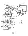
- FIG. 7 shows the internal combustion engine 10 during an initial stage of a new operating cycle.
- the output valving 16, air intake valve 24, fuel injector 26, exhaust valve 34 and fluid admission valves 40, 42 are all closed.
- the control unit 28 sends a signal to cause the air intake valve 24 to be opened and allow fresh aspirant air 200 to flow into the cylinder 12.
- the timing of the opening of the air intake valve 24 is determined by the pressure in the cylinder 12.
- the pressure in the cylinder is determined by reference to temperature indicating signals provided by the temperature sensor 44.
- the cylinder 12 is ready for combustion of the air 200/fuel 206 mixture in the first fluid mass 210.
- Combustion is initiated by the control unit 28 issuing a signal that causes the spark plug 48 to provide a spark 214 in the cylinder 12.
- the combustion taking place in the first fluid mass 210 causes a rapid increase in pressure and expansion of the first fluid mass.
- the expanding first fluid mass 210 acts directly on the second fluid mass 212.
- the pressure in the cylinder 12 is sufficiently high for the second fluid mass 212 to remain in liquid form, although, the rapid temperature increase in the first fluid mass 210 is sufficient to cause the water in the second fluid mass 212 at the interface between the two fluid masses to evaporate so that the interface is predominantly water vapour/steam.
- This evaporation process provides a useful further pressure increase in the cylinder 12 using heat energy that is normally wasted in a conventional internal combustion engine.
- the control unit 28 issues a signal to cause opening of the valve 108 between the heat exchanger and condenser 104 so that exhaust gases can flow from the heat exchanger into the condenser.
- the valve 108 opens, there is a partial vacuum in the condenser 104 so the exhaust gases are drawn into the condenser from the cylinder 12 and heat exchanger 100.
- the exhaust outlet valve 112 opens to allow the condenser to vent to atmosphere.
- the pressure in the cylinder 12, heat exchanger 100 and condenser 104 will rapidly fall to a pressure substantially equal to atmospheric pressure.
- the protector 49 is a shield made of any suitable material (ie a material able to withstand the temperatures and pressures that will exist within the cylinder 12 when the engine is in use) and is positioned to protect the spark plug 48 against splashing that might cause it to become damp and/or corroded in a way that might lead to misfires.
- the protector 49 should be shaped and/or positioned such that it does not impede the flow and mixing of the air and fuel entering the cylinder 12 and to minimise the impedance to the spread of the ignition flame through the fuel-air mixture.
- the best shape and position for a particular cylinder configuration can be determined empirically.
- the exhaust outlet 110 is permanently open to atmosphere.
- closing of the exhaust valve 34 and opening of the air intake valve 24 overlaps so that the inflowing air can scavenge the cylinder.
- the timing of the overlap of the opening of the air intake valve 24 and closing of the exhaust valve 34 can be determined empirically with a view to obtaining a desired level of performance from the internal combustion engine.
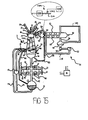
- Figure 15 also illustrates a system 280 for providing a combustible hydrogen containing compound in the steam that is injected into the cylinder 12 via the steam control valve 136.
- This combustible hydrogen containing compound is provided for promoting steam reformation in the cylinder 12.
- the combustible mixture provided in the cylinder 12 is made fuel rich to provide an excess of hydrocarbons for promoting steam reformation in the cylinder 12 when steam is injected into the cylinder via the steam control valve 136.
- the system 280 can be used to provide some or all of the fuel for the steam reformation process.
- the modified internal combustion engine 10 could be provided with a pressure sensor, including a temperature sensor such as a thermocouple, in addition to the infrared sensing temperature device (or other optical temperature sensing device). It will also be appreciated that the internal combustion engine shown in Figures 1 to 12 could be fitted with an infrared temperature sensor (or other optical sensor) instead of or in addition to the pressure sensor already shown and may be provided with a system 280 for adding a combustible hydrogen containing compound to the steam upstream of the steam control valve 136.
- a pressure sensor including a temperature sensor such as a thermocouple, in addition to the infrared sensing temperature device (or other optical temperature sensing device).
- the internal combustion engine shown in Figures 1 to 12 could be fitted with an infrared temperature sensor (or other optical sensor) instead of or in addition to the pressure sensor already shown and may be provided with a system 280 for adding a combustible hydrogen containing compound to the steam upstream of the steam control valve 136.
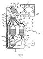
- control unit 728 initiates a new combustion cycle by signalling the air intake valve 724 to open.
- air intake valve 724 opens, aspirant air (indicated by arrows 1042) is sucked into the cylinder 712 to replace the vacuum and form the first fluid mass 1022.
- the air intake valve 724 is closed and the fluid admission control valve 740 is signalled to open and allow water from the second reservoir 790 to flow into the cylinder 712 to form the second fluid mass 1024 and pressurise the first fluid mass 1022.
- the control unit 728 signals the fluid admission control valve 740 to close.
- the air intake valve 724 remains open subsequent to closure of the exhaust valve 734 to allow the supercharger 1060 to deliver a mass of high pressure air to form the first fluid mass 1022 at a pressure sufficiently high for spontaneous ignition to occur when fuel is injected into the cylinder.
- the control unit 728 signals the spark plug 1218 to discharge into the combustible mixture to initiate combustion.
- the mixture combusts there is a rapid pressure increase in the first sub-chamber 1226 that causes the ball 1222 to move away from the valve seat 1220 allowing the hot, rapidly expanding, combustion gases 1236 to rush past into the second sub-chamber 1228 to provide a pressure wave that drives against the water forming the second fluid mass 1024 to provide an engine output in the form of a flow of energised water as previously described.
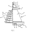
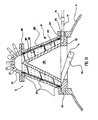
- the ridges 1304 would be arranged to follow the spiral flow path defined by the spiral passages 164, 864. It may also be desirable to provide surface roughening on the parts defining the spiral passages 164, 864. Alternatively, the ridges 1304 could be arranged such that the ridges of adjacent platelets 1302 extend in different directions. This may be beneficial in terms of breaking up the boundary layer and improving fluid flow in the cylinder.
- a second of the two sensors would be located at the level selected as the maximum level beyond which the reservoir should not be filled. In use, while the level of the stored liquid remained below the maximum level, the signal from the second sensor would be different to the reference signal. As soon as the stored liquid level reached the maximum level, the signal would change and substantially the same as the reference signal.
- the walls of the combustion chamber exposed to the moving liquid may, for example, be protected by a ceramic liner or made from stainless steel or similar such material. If an engineering plastics is to be used, it is envisaged the surfaces exposed to the combustion gases will be roughened and/or provided with small recesses, indentations, pockets or the like to promote water retention so as to protect the plastics material from the heat of combustion.
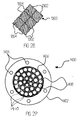
- the surface roughening may, for example, take a form the same as or similar to that shown in Figure 28 .
- the vacuum jacket could be connected with a part of the exhaust system in which a vacuum is to found by ducting fitted with a one-way valve so that if the pressure in the insulating jacket rises above the vacuum in the exhaust system, the one-way valve opens to restore the vacuum.
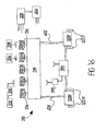
- the engine cylinder(s) of the illustrated embodiments have been described as having one of each valve and one sensor for providing signals indicative of the pressure at each location at which a pressure reading is required. It will be appreciated that multiple valves and/or sensors may be used to provide desired performance levels and/or protection against failure of a single valve or sensor. Thus, for example, there may be twin air intake and/or twin exhaust valves or multiple sensors.
- top ups can be made.
- Various mechanisms may be provided for providing the top up. For example, the level in the first reservoir at start up may be sensed and if the level is found to be insufficient, a top up flow provided from the reservoir. Alternatively, top ups could be made by periodic injection directly into the cylinder(s) from the reservoir 110.
- a free floating separating member disposed between the combustion gases and the working fluid (liquid). It is envisaged that such a separating member, which may be made of any suitable material and is free to reciprocate in the cylinder in response to changes in the respective pressures acting on it, will assist in providing an even transmission of energy from the combustion gases to the liquid across substantially the whole width of the cylinder. Such a separating member may also be desirable to limit contamination of the liquid by the fuel and/or products of combustion of the first fluid mass. It will be appreciated that the separating member can be completely free to move and there is no need to provide sealing between the separating member and the cylinder wall since, in effect, the sealing is provided by the liquid.
- engine manufacturers may supply the engine already filled with the working fluid (liquid) or the working fluid may be added later by a vehicle manufacturer or, for non-vehicular applications, the manufacturer of the equipment with which the internal combustion engine is supplied, or by party who sells the engine or equipment in which it is included, or the end user.
Landscapes
- Engineering & Computer Science (AREA)
- Chemical & Material Sciences (AREA)
- Mechanical Engineering (AREA)
- General Engineering & Computer Science (AREA)
- Combustion & Propulsion (AREA)
- Chemical Kinetics & Catalysis (AREA)
- General Chemical & Material Sciences (AREA)
- Oil, Petroleum & Natural Gas (AREA)
- Output Control And Ontrol Of Special Type Engine (AREA)
- Hydraulic Motors (AREA)
- Engine Equipment That Uses Special Cycles (AREA)
- Hydrogen, Water And Hydrids (AREA)
Applications Claiming Priority (3)
| Application Number | Priority Date | Filing Date | Title |
|---|---|---|---|
| GB0802714A GB2457476A (en) | 2008-02-13 | 2008-02-13 | Internal combustion engine with fluid, eg liquid, output |
| GB0900159.5A GB2457350B (en) | 2008-02-13 | 2009-01-07 | Internal combustion engines |
| EP09710565.4A EP2240670B1 (de) | 2008-02-13 | 2009-02-13 | Verbrennungsmotoren |
Related Parent Applications (2)
| Application Number | Title | Priority Date | Filing Date |
|---|---|---|---|
| EP09710565.4A Division-Into EP2240670B1 (de) | 2008-02-13 | 2009-02-13 | Verbrennungsmotoren |
| EP09710565.4 Division | 2009-02-13 |
Publications (1)
| Publication Number | Publication Date |
|---|---|
| EP2317153A2 true EP2317153A2 (de) | 2011-05-04 |
Family
ID=39247634
Family Applications (6)
| Application Number | Title | Priority Date | Filing Date |
|---|---|---|---|
| EP10159075A Withdrawn EP2317153A2 (de) | 2008-02-13 | 2009-02-13 | Verbrennungskraftmaschine |
| EP09710565.4A Active EP2240670B1 (de) | 2008-02-13 | 2009-02-13 | Verbrennungsmotoren |
| EP10159074A Withdrawn EP2317151A2 (de) | 2008-02-13 | 2009-02-13 | Verbrennungskraftmaschine |
| EP09710632.2A Not-in-force EP2257711B1 (de) | 2008-02-13 | 2009-02-13 | Verbrennungsmotoren |
| EP10159073A Withdrawn EP2317152A2 (de) | 2008-02-13 | 2009-02-13 | Verbrennungskraftmaschine |
| EP09709497A Withdrawn EP2257692A1 (de) | 2008-02-13 | 2009-02-13 | Verbrennungsmotoren |
Family Applications After (5)
| Application Number | Title | Priority Date | Filing Date |
|---|---|---|---|
| EP09710565.4A Active EP2240670B1 (de) | 2008-02-13 | 2009-02-13 | Verbrennungsmotoren |
| EP10159074A Withdrawn EP2317151A2 (de) | 2008-02-13 | 2009-02-13 | Verbrennungskraftmaschine |
| EP09710632.2A Not-in-force EP2257711B1 (de) | 2008-02-13 | 2009-02-13 | Verbrennungsmotoren |
| EP10159073A Withdrawn EP2317152A2 (de) | 2008-02-13 | 2009-02-13 | Verbrennungskraftmaschine |
| EP09709497A Withdrawn EP2257692A1 (de) | 2008-02-13 | 2009-02-13 | Verbrennungsmotoren |
Country Status (10)
| Country | Link |
|---|---|
| US (4) | US8881691B2 (de) |
| EP (6) | EP2317153A2 (de) |
| JP (2) | JP5572792B2 (de) |
| KR (3) | KR101580904B1 (de) |
| CN (1) | CN102007271B (de) |
| BR (1) | BRPI0908081A2 (de) |
| CA (2) | CA2715244C (de) |
| GB (3) | GB2457476A (de) |
| RU (1) | RU2495252C2 (de) |
| WO (4) | WO2009101421A1 (de) |
Families Citing this family (31)
| Publication number | Priority date | Publication date | Assignee | Title |
|---|---|---|---|---|
| US9593625B2 (en) | 2008-02-13 | 2017-03-14 | Nigel A. Buchanan | Internal combustion engines |
| GB2457476A (en) | 2008-02-13 | 2009-08-19 | Nigel Alexander Buchanan | Internal combustion engine with fluid, eg liquid, output |
| WO2010030864A2 (en) * | 2008-09-11 | 2010-03-18 | Will Weldon Mathews | Hybrid combustion energy conversion engines |
| NO332744B1 (no) * | 2009-01-08 | 2013-01-02 | Andersen Erling R | Hydrogendrevet energiomformer |
| US9068743B2 (en) * | 2009-02-26 | 2015-06-30 | 8 Rivers Capital, LLC & Palmer Labs, LLC | Apparatus for combusting a fuel at high pressure and high temperature, and associated system |
| US8986002B2 (en) | 2009-02-26 | 2015-03-24 | 8 Rivers Capital, Llc | Apparatus for combusting a fuel at high pressure and high temperature, and associated system |
| US9416728B2 (en) * | 2009-02-26 | 2016-08-16 | 8 Rivers Capital, Llc | Apparatus and method for combusting a fuel at high pressure and high temperature, and associated system and device |
| GB2472821A (en) | 2009-08-19 | 2011-02-23 | Nigel Alexander Buchanan | Diaphragm IC engine with aqueous barrier and direct hydraulic output |
| WO2011090785A2 (en) * | 2010-01-19 | 2011-07-28 | Marvin Wesley Ward | System, apparatus and method for clean, multi-energy generation |
| JP5494050B2 (ja) * | 2010-03-15 | 2014-05-14 | 株式会社デンソー | 熱機関 |
| US20120006294A1 (en) * | 2010-07-06 | 2012-01-12 | Sam Wolanyk | Isolated cool air intake |
| JP5257713B2 (ja) * | 2011-02-10 | 2013-08-07 | アイシン精機株式会社 | 車両用冷却装置 |
| KR20130063672A (ko) * | 2011-12-07 | 2013-06-17 | 현대자동차주식회사 | 복합 동력 사이클 엔진 |
| RU2527005C1 (ru) * | 2013-03-29 | 2014-08-27 | федеральное государственное бюджетное образовательное учреждение высшего профессионального образования "Российский государственный университет нефти и газа имени И.М. Губкина" | Способ подготовки жидкого топлива к сжиганию в камере сгорания |
| GB201316775D0 (en) * | 2013-09-20 | 2013-11-06 | Rosen Ian K | Internal combustion engines |
| US20150285135A1 (en) * | 2014-04-04 | 2015-10-08 | Nexovation, Inc. | Combustion engine including an air injector, and power generating system including the combustion engine |
| CA2946749C (en) * | 2014-04-23 | 2019-01-15 | American United Energy, Inc. | Fuel control systems for operating gasoline engines based on ethanol-water-hydrogen mixture fuels |
| CN105020058B (zh) * | 2015-08-03 | 2018-11-16 | 湖州新奥利吸附材料有限公司 | 一种内燃机气体混合装置 |
| PL3423700T3 (pl) * | 2016-03-04 | 2024-09-02 | Indopar B.V. | Moduł kondycjonowania płynów gazowych |
| US9957888B2 (en) * | 2016-03-30 | 2018-05-01 | General Electric Company | System for generating syngas and an associated method thereof |
| US10850610B2 (en) * | 2016-09-30 | 2020-12-01 | Tony Matijevich | Alternative fuel system |
| CN110291293B (zh) * | 2017-02-16 | 2021-07-20 | 液体控制有限公司 | 用于输送液体燃料的系统和方法 |
| ES2989187T3 (es) | 2017-03-07 | 2024-11-25 | 8 Rivers Capital Llc | Sistemas y métodos de funcionamiento de una cámara de combustión de combustible flexible para una turbina de gas |
| US10859264B2 (en) | 2017-03-07 | 2020-12-08 | 8 Rivers Capital, Llc | System and method for combustion of non-gaseous fuels and derivatives thereof |
| CN111868368A (zh) * | 2018-01-18 | 2020-10-30 | 热电技术控股公司 | 浮动头活塞组件 |
| CN108427494B (zh) * | 2018-05-15 | 2024-06-28 | 深圳昂湃技术股份有限公司 | 一种液冷散热系统及其水箱 |
| CA3106955A1 (en) | 2018-07-23 | 2020-01-30 | 8 Rivers Capital, Llc | System and method for power generation with flameless combustion |
| KR102856495B1 (ko) | 2019-02-05 | 2025-09-05 | 닛산 가가쿠 가부시키가이샤 | 액정 배향제, 액정 배향막 및 그것을 사용한 액정 표시 소자 |
| GB202013803D0 (en) | 2020-09-02 | 2020-10-14 | Hydro Ject Llc | Catalyst mounting in internal combustion engines |
| DE102021131835B4 (de) * | 2021-03-03 | 2025-05-08 | GM Global Technology Operations LLC | Verbesserte motorzündstrategie |
| CN114263530B (zh) * | 2021-12-30 | 2022-09-27 | 重庆望江摩托车制造有限公司 | 一种混合燃油与氢气的新能源摩托车 |
Citations (1)
| Publication number | Priority date | Publication date | Assignee | Title |
|---|---|---|---|---|
| US5659133A (en) | 1996-04-22 | 1997-08-19 | Astropower, Inc. | High-temperature optical combustion chamber sensor |
Family Cites Families (70)
| Publication number | Priority date | Publication date | Assignee | Title |
|---|---|---|---|---|
| GB190516711A (en) * | 1904-08-17 | Pfannkuche Elten Alfred | An Improved Method of and Means for Obtaining Moist Compressed Air or Gas. | |
| GB191020934A (en) * | 1910-09-08 | 1911-05-25 | Graydon Poore | An Improved Pump for Raising Liquids. |
| US1336392A (en) * | 1918-10-07 | 1920-04-06 | Th Arthur L S | Internal-combustion motor |
| DE590890C (de) | 1931-01-14 | 1934-01-12 | Erwin Mueller Bralitz Dipl Ing | Explosions-Vakuum-Fluessigkeitsheber |
| FR1011313A (fr) * | 1949-01-15 | 1952-06-23 | Brev Tamassy Soc D Expl Des | Dispositif pour provoquer le déplacement de l'eau |
| US2872775A (en) * | 1954-06-17 | 1959-02-10 | Tavannes Watch Co Sa | Watch movement |
| US2872778A (en) * | 1955-12-27 | 1959-02-10 | Harold B Dane | Internal combustion powered fluid motor and hydraulic propulsion system |
| US3361353A (en) * | 1965-10-20 | 1968-01-02 | Mitchell W. Millman | Method and apparatus for injection of liquid fuels |
| GB1191130A (en) * | 1967-01-26 | 1970-05-06 | Cleveland Technical Ct Inc | Liquid Piston Internal Combustion Apparatus |
| US3520279A (en) * | 1967-11-16 | 1970-07-14 | Maurice W Hoover | Continuous vacuum impregnator |
| US3608660A (en) * | 1969-02-03 | 1971-09-28 | Combustion Power | Smog-free automobile and method of operating same |
| US3815555A (en) * | 1971-03-19 | 1974-06-11 | Europ De Propulsion Sa | Hydraulic heat engine |
| US3969899A (en) * | 1972-04-18 | 1976-07-20 | Sadaharu Nakazawa | Fuel burning apparatus and heat engine incorporating the same |
| US3845555A (en) * | 1973-04-26 | 1974-11-05 | Hanson Design Inc | Bottle cutter |
| US3946711A (en) * | 1974-04-08 | 1976-03-30 | Wigal Voorhis F | Hydrogen fired ignition system for internal combustion engines |
| DE2612961C2 (de) * | 1976-03-26 | 1984-07-19 | Hans Joachim Dipl.-Ing. 2150 Buxtehude Wendt | Freikolbenbrennkraftmaschine mit Mitteln zur Leistungsregelung |
| US4087548A (en) * | 1976-05-10 | 1978-05-02 | American Cyanamid Company | Complement inhibitors |
| GB1511863A (en) * | 1976-06-08 | 1978-05-24 | Picken D | Boat propulsion unit |
| US4113589A (en) * | 1977-04-25 | 1978-09-12 | Leach Sam L | High intensity energy transfer technique |
| JPS5439524A (en) * | 1977-09-05 | 1979-03-27 | Hitachi Ltd | Display unit with next screen display function |
| US4380970A (en) * | 1979-08-01 | 1983-04-26 | Davis Roy A | Combustion engines |
| US4567857A (en) * | 1980-02-26 | 1986-02-04 | The United States Of America As Represented By The Administrator Of The National Aeronautics And Space Administration | Combustion engine system |
| US4508064A (en) * | 1981-11-12 | 1985-04-02 | Katsuji Baba | Internal combustion engine of hydrogen gas |
| US4530317A (en) * | 1984-04-20 | 1985-07-23 | Eaton Corporation | Variable displacement free piston engine |
| FR2585769B1 (fr) * | 1985-08-01 | 1990-08-31 | Malherbe Andre | Dispositif de production d'energie mecanique continue par moyens pyrotechniques |
| US4777801A (en) * | 1987-07-13 | 1988-10-18 | Porter David R | Energy conversion apparatus |
| US5016441A (en) * | 1987-10-07 | 1991-05-21 | Pinto Adolf P | Heat regeneration in engines |
| US4873840A (en) * | 1988-02-11 | 1989-10-17 | Swedsteam Ab | Energy co-generation system |
| US5092281A (en) * | 1988-07-26 | 1992-03-03 | Kabushiki Kaisha Toyoda Jidoshokki Seisakusho | Hydrogen engine system |
| US5156114A (en) * | 1989-11-22 | 1992-10-20 | Gunnerman Rudolf W | Aqueous fuel for internal combustion engine and method of combustion |
| JP3116169B2 (ja) * | 1991-04-17 | 2000-12-11 | 本田技研工業株式会社 | 水素エンジンにおける燃料制御方法 |
| US5127369A (en) * | 1991-05-21 | 1992-07-07 | Goldshtik Mikhail A | Engine employing rotating liquid as a piston |
| US5305714A (en) * | 1991-07-03 | 1994-04-26 | Nippon Soken, Inc. | Fuel supply system for an internal combustion engine |
| US5237964A (en) * | 1992-11-30 | 1993-08-24 | Constantin Tomoiu | Internal combustion engine with a new sequence of operation and combustion |
| RU2042844C1 (ru) * | 1993-04-12 | 1995-08-27 | Геннадий Павлович Примов | Двигатель внутреннего сгорания |
| US5387398A (en) * | 1993-12-03 | 1995-02-07 | Aerojet General Corporation | Supercritical water oxidation reactor with wall conduits for boundary flow control |
| US5713202A (en) * | 1994-04-04 | 1998-02-03 | Energy Conservation Partnership, Ltd. | Methods for producing hydro-electric power |
| US5647734A (en) * | 1995-06-07 | 1997-07-15 | Milleron; Norman | Hydraulic combustion accumulator |
| RU2103518C1 (ru) * | 1995-09-19 | 1998-01-27 | Валерий Туркубеевич Пчентлешев | Поршневая машина |
| DE19646754A1 (de) * | 1996-11-04 | 1998-05-07 | Seydlitz Goetz Dieter | Allkraftstoffmotor |
| US6112522A (en) * | 1998-11-10 | 2000-09-05 | Wright; Harlow | Total flow liquid piston engine |
| US6182615B1 (en) * | 1999-03-19 | 2001-02-06 | Charles H. Kershaw | Combustion-driven hydroelectric generating system |
| US6506025B1 (en) * | 1999-06-23 | 2003-01-14 | California Institute Of Technology | Bladeless pump |
| AU2001284386A1 (en) * | 2000-09-11 | 2002-03-22 | Petur Thordarson | Hydrogen motor |
| US6551076B2 (en) * | 2000-12-15 | 2003-04-22 | Jim L. Boulware | Fuel/hydraulic engine system |
| US6835219B2 (en) * | 2001-05-14 | 2004-12-28 | General Motors Corporation | Rapid startup of fuel processor using water adsorption |
| NL1018858C1 (nl) * | 2001-08-30 | 2003-03-03 | Maarten Johannes Van Der Burgt | Inrichting voor het omzetten van potentiele chemische energie in arbeid. |
| US6820706B2 (en) * | 2001-09-25 | 2004-11-23 | Energy Conversion Devices, Inc. | Method and system for hydrogen powered internal combustion engine |
| US6659049B2 (en) * | 2002-02-22 | 2003-12-09 | Proton Energy Systems | Hydrogen generation apparatus for internal combustion engines and method thereof |
| KR100995162B1 (ko) * | 2002-02-28 | 2010-11-17 | 니콜라이 시콜닉 | 연소기관 |
| CN2578534Y (zh) * | 2002-11-04 | 2003-10-08 | 张建稳 | 水燃机 |
| US7416137B2 (en) * | 2003-01-22 | 2008-08-26 | Vast Power Systems, Inc. | Thermodynamic cycles using thermal diluent |
| US7343732B2 (en) * | 2003-03-04 | 2008-03-18 | Aerojet-General Corporation | Rocket engine chamber with layered internal wall channels |
| US20090194042A1 (en) * | 2004-07-13 | 2009-08-06 | Workman Alan J | Fuel Supply System for a Vehicle Including a Vaporization Device for Converting Fuel and Water into Hydrogen |
| JP4003764B2 (ja) * | 2004-08-04 | 2007-11-07 | トヨタ自動車株式会社 | 水素添加内燃機関の制御装置 |
| US7100542B2 (en) * | 2004-11-04 | 2006-09-05 | Ehresoft Technologies, Inc. | Hydrogen oxygen generation system for an internal combustion engine |
| US7089888B2 (en) * | 2004-12-30 | 2006-08-15 | Council Of Scientific And Industrial Research | Device for production of hydrogen from effluents of internal combustion engines |
| US20060196189A1 (en) * | 2005-03-04 | 2006-09-07 | Rabbat Michel G | Rabbat engine |
| JP2006248814A (ja) * | 2005-03-09 | 2006-09-21 | Hitachi Ltd | 水素供給装置および水素供給方法 |
| US7789047B2 (en) * | 2005-05-24 | 2010-09-07 | Toyota Jidosha Kabushiki Kaisha | Hydrogen-fueled internal combustion engine |
| JP4887836B2 (ja) * | 2006-03-01 | 2012-02-29 | 日産自動車株式会社 | 内燃機関 |
| AT503126B1 (de) * | 2006-06-28 | 2007-08-15 | Figl Gerhard | Verbrennungskraftmaschine |
| JP2008014139A (ja) * | 2006-06-30 | 2008-01-24 | Toyota Central Res & Dev Lab Inc | 内燃機関 |
| JP4586780B2 (ja) * | 2006-09-07 | 2010-11-24 | トヨタ自動車株式会社 | 作動ガス循環型エンジン |
| JP4687666B2 (ja) * | 2007-02-28 | 2011-05-25 | 株式会社日立製作所 | エンジンシステム |
| RU2364735C2 (ru) * | 2007-04-23 | 2009-08-20 | Иван Николаевич Шеремет | Способ создания жидкостного двигателя внутреннего сгорания и жидкостной двигатель |
| US8381522B2 (en) * | 2007-05-02 | 2013-02-26 | Christian Hansen, Jr. | Steam powered engine |
| US8635985B2 (en) * | 2008-01-07 | 2014-01-28 | Mcalister Technologies, Llc | Integrated fuel injectors and igniters and associated methods of use and manufacture |
| GB2457476A (en) * | 2008-02-13 | 2009-08-19 | Nigel Alexander Buchanan | Internal combustion engine with fluid, eg liquid, output |
| US8375900B2 (en) * | 2009-04-15 | 2013-02-19 | John Berkyto | External combustion engine and method of converting internal combustion engine thereto |
-
2008
- 2008-02-13 GB GB0802714A patent/GB2457476A/en not_active Withdrawn
-
2009
- 2009-01-07 GB GB0900161.1A patent/GB2457351B/en not_active Expired - Fee Related
- 2009-01-07 GB GB0900159.5A patent/GB2457350B/en not_active Expired - Fee Related
- 2009-02-13 CA CA2715244A patent/CA2715244C/en not_active Expired - Fee Related
- 2009-02-13 JP JP2010546397A patent/JP5572792B2/ja not_active Expired - Fee Related
- 2009-02-13 BR BRPI0908081-3A patent/BRPI0908081A2/pt not_active IP Right Cessation
- 2009-02-13 EP EP10159075A patent/EP2317153A2/de not_active Withdrawn
- 2009-02-13 KR KR1020107010316A patent/KR101580904B1/ko not_active Expired - Fee Related
- 2009-02-13 WO PCT/GB2009/000408 patent/WO2009101421A1/en not_active Ceased
- 2009-02-13 EP EP09710565.4A patent/EP2240670B1/de active Active
- 2009-02-13 EP EP10159074A patent/EP2317151A2/de not_active Withdrawn
- 2009-02-13 WO PCT/GB2009/000413 patent/WO2009101423A1/en not_active Ceased
- 2009-02-13 KR KR1020127033324A patent/KR101739935B1/ko not_active Expired - Fee Related
- 2009-02-13 EP EP09710632.2A patent/EP2257711B1/de not_active Not-in-force
- 2009-02-13 CN CN200980113049.5A patent/CN102007271B/zh not_active Expired - Fee Related
- 2009-02-13 KR KR1020157020244A patent/KR101590325B1/ko not_active Expired - Fee Related
- 2009-02-13 US US12/867,660 patent/US8881691B2/en active Active
- 2009-02-13 US US12/867,674 patent/US8733300B2/en active Active
- 2009-02-13 EP EP10159073A patent/EP2317152A2/de not_active Withdrawn
- 2009-02-13 EP EP09709497A patent/EP2257692A1/de not_active Withdrawn
- 2009-02-13 US US12/864,812 patent/US8985065B2/en active Active
- 2009-02-13 CA CA2715531A patent/CA2715531C/en not_active Expired - Fee Related
- 2009-02-13 RU RU2010137871/06A patent/RU2495252C2/ru not_active IP Right Cessation
- 2009-02-13 WO PCT/GB2009/000407 patent/WO2009101420A1/en not_active Ceased
- 2009-02-13 WO PCT/GB2009/000406 patent/WO2009101419A1/en not_active Ceased
-
2014
- 2014-05-02 JP JP2014095559A patent/JP6100201B2/ja not_active Expired - Fee Related
- 2014-10-24 US US14/522,734 patent/US9371732B2/en not_active Expired - Fee Related
Patent Citations (1)
| Publication number | Priority date | Publication date | Assignee | Title |
|---|---|---|---|---|
| US5659133A (en) | 1996-04-22 | 1997-08-19 | Astropower, Inc. | High-temperature optical combustion chamber sensor |
Also Published As
Similar Documents
| Publication | Publication Date | Title |
|---|---|---|
| EP2240670B1 (de) | Verbrennungsmotoren | |
| US8661816B2 (en) | Hybrid combustion energy conversion engines | |
| US20120279205A1 (en) | Internal combustion engines | |
| WO2023166286A1 (en) | Hydrogen - oxygen powered engine system and associated methods | |
| US9593625B2 (en) | Internal combustion engines |
Legal Events
| Date | Code | Title | Description |
|---|---|---|---|
| PUAI | Public reference made under article 153(3) epc to a published international application that has entered the european phase |
Free format text: ORIGINAL CODE: 0009012 |
|
| AC | Divisional application: reference to earlier application |
Ref document number: 2240670 Country of ref document: EP Kind code of ref document: P |
|
| AK | Designated contracting states |
Kind code of ref document: A2 Designated state(s): AT BE BG CH CY CZ DE DK EE ES FI FR GB GR HR HU IE IS IT LI LT LU LV MC MK MT NL NO PL PT RO SE SI SK TR |
|
| AX | Request for extension of the european patent |
Extension state: AL BA RS |
|
| STAA | Information on the status of an ep patent application or granted ep patent |
Free format text: STATUS: THE APPLICATION IS DEEMED TO BE WITHDRAWN |
|
| 18D | Application deemed to be withdrawn |
Effective date: 20150901 |