EP2316751A1 - Covering device for silos intended for storing solid or liquid products - Google Patents
Covering device for silos intended for storing solid or liquid products Download PDFInfo
- Publication number
- EP2316751A1 EP2316751A1 EP10179626A EP10179626A EP2316751A1 EP 2316751 A1 EP2316751 A1 EP 2316751A1 EP 10179626 A EP10179626 A EP 10179626A EP 10179626 A EP10179626 A EP 10179626A EP 2316751 A1 EP2316751 A1 EP 2316751A1
- Authority
- EP
- European Patent Office
- Prior art keywords
- panels
- returns
- coating device
- panel
- intended
- Prior art date
- Legal status (The legal status is an assumption and is not a legal conclusion. Google has not performed a legal analysis and makes no representation as to the accuracy of the status listed.)
- Granted
Links
- 239000012263 liquid product Substances 0.000 title claims description 5
- 239000012265 solid product Substances 0.000 title claims description 5
- 239000011248 coating agent Substances 0.000 claims abstract description 33
- 238000000576 coating method Methods 0.000 claims abstract description 33
- 229910001220 stainless steel Inorganic materials 0.000 claims abstract description 15
- 239000010935 stainless steel Substances 0.000 claims abstract description 15
- 230000002093 peripheral effect Effects 0.000 claims abstract description 13
- 238000000926 separation method Methods 0.000 claims abstract description 12
- 239000011324 bead Substances 0.000 claims abstract description 11
- 238000000034 method Methods 0.000 claims abstract description 6
- 238000005304 joining Methods 0.000 claims abstract description 5
- XLYOFNOQVPJJNP-UHFFFAOYSA-N water Substances O XLYOFNOQVPJJNP-UHFFFAOYSA-N 0.000 claims description 22
- 238000003466 welding Methods 0.000 claims description 16
- 238000007789 sealing Methods 0.000 claims description 11
- 238000013016 damping Methods 0.000 claims description 9
- 238000003860 storage Methods 0.000 claims description 4
- 239000011261 inert gas Substances 0.000 abstract description 4
- 229910052751 metal Inorganic materials 0.000 abstract description 3
- 239000002184 metal Substances 0.000 abstract description 3
- WFKWXMTUELFFGS-UHFFFAOYSA-N tungsten Chemical compound [W] WFKWXMTUELFFGS-UHFFFAOYSA-N 0.000 abstract description 2
- 229910052721 tungsten Inorganic materials 0.000 abstract description 2
- 239000010937 tungsten Substances 0.000 abstract description 2
- 238000005253 cladding Methods 0.000 description 6
- 238000004873 anchoring Methods 0.000 description 5
- 125000006850 spacer group Chemical group 0.000 description 5
- 230000008901 benefit Effects 0.000 description 4
- 238000009434 installation Methods 0.000 description 4
- 239000000047 product Substances 0.000 description 4
- 238000010276 construction Methods 0.000 description 3
- 230000007797 corrosion Effects 0.000 description 3
- 238000005260 corrosion Methods 0.000 description 3
- 230000007547 defect Effects 0.000 description 3
- 238000002955 isolation Methods 0.000 description 3
- 239000000463 material Substances 0.000 description 3
- 238000011084 recovery Methods 0.000 description 3
- 238000009418 renovation Methods 0.000 description 3
- 239000003351 stiffener Substances 0.000 description 3
- 230000006978 adaptation Effects 0.000 description 2
- 230000015572 biosynthetic process Effects 0.000 description 2
- 230000015556 catabolic process Effects 0.000 description 2
- 239000004567 concrete Substances 0.000 description 2
- 238000006731 degradation reaction Methods 0.000 description 2
- 239000003651 drinking water Substances 0.000 description 2
- 235000020188 drinking water Nutrition 0.000 description 2
- 239000011810 insulating material Substances 0.000 description 2
- 230000003014 reinforcing effect Effects 0.000 description 2
- 239000011347 resin Substances 0.000 description 2
- 229920005989 resin Polymers 0.000 description 2
- 239000003566 sealing material Substances 0.000 description 2
- 239000007787 solid Substances 0.000 description 2
- 241000239290 Araneae Species 0.000 description 1
- ZAMOUSCENKQFHK-UHFFFAOYSA-N Chlorine atom Chemical compound [Cl] ZAMOUSCENKQFHK-UHFFFAOYSA-N 0.000 description 1
- 239000004593 Epoxy Substances 0.000 description 1
- 230000001154 acute effect Effects 0.000 description 1
- 210000003423 ankle Anatomy 0.000 description 1
- 239000011230 binding agent Substances 0.000 description 1
- 230000000740 bleeding effect Effects 0.000 description 1
- 230000000903 blocking effect Effects 0.000 description 1
- 230000005587 bubbling Effects 0.000 description 1
- 210000004027 cell Anatomy 0.000 description 1
- 239000004568 cement Substances 0.000 description 1
- 229910052801 chlorine Inorganic materials 0.000 description 1
- 239000000460 chlorine Substances 0.000 description 1
- 238000004140 cleaning Methods 0.000 description 1
- 238000011109 contamination Methods 0.000 description 1
- 238000010924 continuous production Methods 0.000 description 1
- 230000002542 deteriorative effect Effects 0.000 description 1
- 239000011440 grout Substances 0.000 description 1
- 238000003780 insertion Methods 0.000 description 1
- 230000037431 insertion Effects 0.000 description 1
- 238000004519 manufacturing process Methods 0.000 description 1
- 239000004570 mortar (masonry) Substances 0.000 description 1
- 238000002161 passivation Methods 0.000 description 1
- 238000005554 pickling Methods 0.000 description 1
- 239000011505 plaster Substances 0.000 description 1
- 239000004033 plastic Substances 0.000 description 1
- 239000006223 plastic coating Substances 0.000 description 1
- 238000007747 plating Methods 0.000 description 1
- 238000003825 pressing Methods 0.000 description 1
- 230000001681 protective effect Effects 0.000 description 1
- 239000000126 substance Substances 0.000 description 1
Images


Classifications
-
- B—PERFORMING OPERATIONS; TRANSPORTING
- B65—CONVEYING; PACKING; STORING; HANDLING THIN OR FILAMENTARY MATERIAL
- B65D—CONTAINERS FOR STORAGE OR TRANSPORT OF ARTICLES OR MATERIALS, e.g. BAGS, BARRELS, BOTTLES, BOXES, CANS, CARTONS, CRATES, DRUMS, JARS, TANKS, HOPPERS, FORWARDING CONTAINERS; ACCESSORIES, CLOSURES, OR FITTINGS THEREFOR; PACKAGING ELEMENTS; PACKAGES
- B65D90/00—Component parts, details or accessories for large containers
- B65D90/02—Wall construction
- B65D90/04—Linings
- B65D90/041—Rigid liners fixed to the container
- B65D90/042—Rigid liners fixed to the container fixed pointwise or linewise
- B65D90/043—Rigid liners fixed to the container fixed pointwise or linewise the liners being in the form of tiles or panels
-
- B—PERFORMING OPERATIONS; TRANSPORTING
- B65—CONVEYING; PACKING; STORING; HANDLING THIN OR FILAMENTARY MATERIAL
- B65D—CONTAINERS FOR STORAGE OR TRANSPORT OF ARTICLES OR MATERIALS, e.g. BAGS, BARRELS, BOTTLES, BOXES, CANS, CARTONS, CRATES, DRUMS, JARS, TANKS, HOPPERS, FORWARDING CONTAINERS; ACCESSORIES, CLOSURES, OR FITTINGS THEREFOR; PACKAGING ELEMENTS; PACKAGES
- B65D90/00—Component parts, details or accessories for large containers
- B65D90/02—Wall construction
- B65D90/08—Interconnections of wall parts; Sealing means therefor
-
- E—FIXED CONSTRUCTIONS
- E04—BUILDING
- E04H—BUILDINGS OR LIKE STRUCTURES FOR PARTICULAR PURPOSES; SWIMMING OR SPLASH BATHS OR POOLS; MASTS; FENCING; TENTS OR CANOPIES, IN GENERAL
- E04H7/00—Construction or assembling of bulk storage containers employing civil engineering techniques in situ or off the site
- E04H7/02—Containers for fluids or gases; Supports therefor
- E04H7/18—Containers for fluids or gases; Supports therefor mainly of concrete, e.g. reinforced concrete, or other stone-like material
-
- E—FIXED CONSTRUCTIONS
- E04—BUILDING
- E04H—BUILDINGS OR LIKE STRUCTURES FOR PARTICULAR PURPOSES; SWIMMING OR SPLASH BATHS OR POOLS; MASTS; FENCING; TENTS OR CANOPIES, IN GENERAL
- E04H7/00—Construction or assembling of bulk storage containers employing civil engineering techniques in situ or off the site
- E04H7/22—Containers for fluent solids, e.g. silos, bunkers; Supports therefor
- E04H7/24—Constructions, with or without perforated walls, depending on the use of specified materials
- E04H7/26—Constructions, with or without perforated walls, depending on the use of specified materials mainly of concrete, e.g. reinforced concrete or other stone-like materials
Definitions
- the invention relates to a coating device, preferably made of stainless steel, for sealing all types of structures storing solid or liquid products such as water tower tanks, underground or underground tanks, wine tanks, ponds, silos, etc ...
- the invention will be more particularly described with reference to the casing of a water tower reservoir, without being limited thereto.
- these devices have a limited life, the coating deteriorating over time by the appearance of blistering bubbling, cracks, or tears for the liner, or other degradations that may in particular impact the health requirements.
- the patent application FR 2 769 657 teaches such use.
- the casing described in this document is to have against the entire surface of the tank wall a spider web frame on which are reported by welding flat stainless steel sheets.
- the framework is formed of rectangular section tubes fixed to the concrete tank by fixing lugs which are welded to the tubes on the one hand, and secured to the tank wall by chemical dowels on the other hand.
- the sheets of the latter solution are flat with two opposite general faces. Each sheet is pressed peripherally by one of its faces against several parallelepipedal tubes forming support frame for the sheet. A weld is made at the edge of the sheet and against the faces of the tubes on which the sheet is applied.
- the advantage of this solution is to provide a casing which is not placed on the surface of the tank. No patching is to be performed, and the deformations over time that could undergo the surface of the tank do not affect the tightness of the coating completely disengaged from said surface.
- this structure has the disadvantage of proceeding to the implementation of a preliminary framework, involving the design of the frame by the realization of a multitude of tubes to diversified dimensions to reproduce the internal geometry of the tank, as well as its mounting on site.
- the tubes being pressed against the surface of the tank thus adopting its profile, a significant lack of flatness of the surface can cause an absence of coplanarity between two adjacent sheets and the tube connecting them. Despite a weld seam that will be made consistently to catch the resulting game, the seal may not be guaranteed.
- the sheets being flat, they have a thickness adapted to the resistance required for the type of content of the tank.
- the increase in thickness necessarily implies a higher weight for each of the sheets, not facilitating the handling and welding thereof for installation in the tank.
- the purpose of the invention is therefore to provide a waterproof coating device thus forming a casing for the inside of tanks, in particular water tank tanks, which do not have the drawbacks of the prior art and which provide, in particular, easy to implement on site, the device can further advantageously incorporate an antiseismic anchoring system to adapt to media subjected to high stresses.
- the coating device preferably made of stainless steel, intended to seal a structure capable of storing solid or liquid products, comprises a plurality of covering panels each having a core, one of whose faces is intended for form the coating next to stored products, pieces of fasteners intended to ensure the fixing of these panels away from said structure being attached to the panels on the one hand, and to the surface of the structure to be coated on the other hand, as well as weld seams, and is characterized in that that each wallboard, which is in open box-shaped facing of the structure to parry comprises peripheral return extending substantially perpendicularly or at an angle ⁇ with respect to the core in the direction of the structure and so opposed to the coating face, the panels being joined together by joining their returns, fixed together at said returns with the fasteners and welded together by the weld seams at the joint of the souls and in the alignment of the returns, and in that each fastener comprises adjusting means able to adapt the separation distance of a panel to the surface of the structure .
- the formation of panels in the form of boxes and the establishment of localized fasteners at the peripheral lateral returns of the panels provide an easy assembly of these panels together and a quick attachment thereof to the surface to put on.
- the welding which ensures the strength of the entire coating device, can then be operated to ensure the sealing function of said coating.
- Such a device also makes it possible, thanks to the means for adjusting the separation distance of the panels to the structure, these means being advantageously associated with the fasteners which thus form adjustable spacers, to parry the surface being perfectly in line with this one whatever the nature of its profile.
- the fixing of the panels between them imposes to mount them as and when, ensuring to adjust in real time and easily the plumb of the panels with respect to the surface of the structure, and thus gaining in time of implementation. of the device.
- this form of panel with returns further stiffens the panel a completely flat shape when the thickness is relatively small (about 2 mm) and thus provides a better mechanical strength.
- the joining of the panels via the returns provides a full volume at the rear of the joint to be welded, thereby avoiding any phenomenon of rocking during the welding operation and thus preventing any risk of corrosion.
- each fastener comprises two fixing parts, a first part being intended to be integral with the structure, while the second part is secured to the returns of two butted panels, the two parts being connected by means of link constituting the mobile means for adjusting the separation distance of the panel to the surface of the structure.
- These connecting means are for example a threaded screw combined with a nut and a lock nut.
- the panel returns comprise apertures and orifices receiving means of assembly, of the bolting type, cooperating with the fasteners, the light of at least one panel associated with a fastener having an oblong shape. in order to adjust the coplanarity of the souls of the two adjacent panels and allowing the installation of the panels in staggered rows.
- the device comprises at least one evacuation duct arranged so as to pass through the returns of the panels, the duct being intended to be associated with its free ends to flow pipes.
- the separation space from the surface of the structure to the cores of the cladding panels is thus used to house a duct which serves, for example, by being connected via a drain pipe to the outside of the dome of a storage tank. water tower, the evacuation of rainwater. The rainwater is recovered without being discharged along the outer walls of the water tower, avoiding the degradation of these and even the possible annoyance caused by the sound of water runoff.
- Isolation means for example in the form of pre-cut insulating panels or of the injectable type such as insulating mortar grout, can be housed inside the panel between the core and the returns, and intended to fill the separation space of the panels to the structure, avoiding the presence of condensates.
- the returns of the panels are provided with lights or orifices, which for those not serving to assemble the panels together, constitute a guiding means for the evacuation of the condensates. long and inside the panels opposite the structure.
- the weld beads preferably made by the TIG or MIG welding process, are treated by passivation.
- the device may comprise anti-seismic damping systems associated with the fasteners and intended to be sandwiched between the fasteners and the surface of the structure. These systems advantageously provide additional resistance of the device in seismic zone. Such systems will also be associated with the pipe in the form of a flanged compensator interface sleeve.
- the panels arranged against these pipes or poles comprise bores and / or peripheral cuts whose section or profile corresponds to the passage of a pipe and / or pole, means Sealing being intended to be applied to the junction of the panels and the pipe or the post.
- the multiple panels of coating are manufactured in factory with the desired shapes and dimensions, then the device is fixed on site against the internal surface of the structure, which can in particular be a water tower tank, wine vat, pond, silo.
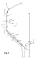
- the figure 1 illustrates a coating device 1 of the invention sealingly sealing the inner surface 2 of a water tank 20.
- the device comprises, according to the invention, cladding panels 10 and fasteners 3, the panels being joined laterally to each other, fixed together and to the surface 2 of the tank via the fasteners 3, and welded to their respective parts. join 4 to obtain the required seal.
- the covering panels 10 are attached at a distance from the surface 2 of the tank. According to the invention, the fasteners 3 allow adjustment of the separation distance of the panels to the surface 2.
- the figure 2a illustrates a schematic enlarged sectional view of the attachment of several adjacent panels, the fasteners 3 being associated on the one hand with the panels 10 by 5A type assembly means bolting, and secondly to the surface 2 of the tank by anchoring means 5.
- This figure 2a has an association with a flat wall, while the figure 2b shows an association with a curved wall.
- the cladding panels 10, the fasteners 3 and their means of assembly and anchoring are made of stainless steel to ensure the durability of the device and avoid any risk of corrosion related to ferric contamination by water intended to be stored in The reservoir.
- the cladding panels 10 are pre-fabricated by being dimensioned such that the arrangement of a multiplicity of panels is adapted to the geometry and the dimensional dimensions of the surface to be covered.
- the panels are transported on site and are ready to be assembled together, attached to the surface 2, and welded at their junction to provide an exposure surface that is flat and sealed in contact with the contents of the tank.
- the figure 3a illustrates in perspective a coating panel 10 of the invention. It has a general box shape with a core 11 and peripheral lateral returns 12.
- the returns 12 extend substantially perpendicularly to the core in the same direction and as illustrated in FIG. figure 3a when it comes to covering a flat surface in accordance with the figure 2a .
- the returns 12 extend relative to the core 15 at an acute angle ⁇ as illustrated in FIG. figure 3b .
- the internal face 13 of the core of the panel delimits with the returns 12 an interior space 14 of the box intended to be disposed facing the surface 2 of the tank in the assembled position of the panel, as visible on the Figures 2a and 2b .
- the opposite outer face 15 of the bottom of the panel is flat and intended to be facing the inside of the tank 20 in contact with the water.
- two adjacent panels 10 are abutted by plating the return 12 of one of the panels against the corresponding return 12 of the other panel and arranging them so that the outer faces 15 of the souls follow the profile of the wall 2 in him being parallel, and form a continuous facing surface facing the water.
- the sealing of the device is obtained by welding beads 40 established at the join 4 of the panels at the outer face 15 of the souls and the initialization of the returns 12 from each of the outer faces.
- Each panel 10 ( figure 3a ) comprises in at least two returns 12 facing each other, on two opposite sides and on a third side, lights 16 preferably arranged at the distal ends of the returns (depending on the free edge of said returns), forming open notches, and intended for cooperate with assembly means of the bolting type for their assembly and their association with fasteners 3.
- the assembly will be better described later with regard to the figure 5 .
- openings 16A which will be intended to cooperate with said lights 16 of an adjacent panel.
- Some orifices are circular in shape, others rather oblong, in ellipse.
- the median and elliptical 16A orifices of the returns allow a staggered assembly of the panels.
- the lights 16 and the orifices 16A are distributed over all the peripheral returns 12 of a panel without all being used for fixing the panel but to facilitate the manufacture of panels by industrial reproducibility, whatever then the method of assembly in staggered or straight.
- the panels can have various geometric shapes.
- the example given in figure 3a proposes a bottom of rectangular section generating a box of parallelepipedic shape rectangle.
- FIG 4a illustrates several examples of embodiment of the section of the core 11 of a panel (square, rectangular, trapezoidal, triangular).
- the triangular and trapezoidal shapes will be especially designed to coat the bottom of the tank.
- the soul of the panels is full to ensure the siding. However, it may have on its surface and in its thickness ( figure 4b ) one or more cuts forming 11A bores, which allows as will be seen later to adapt to the presence of pipes passing through the surface to be coated thus ensuring a facing all around a pipe.
- the perimeter of the core may have one or more specific cuts 11B ( figure 4b ) to fit the outline of posts inherent to the construction of the tank.
- the panels generally have a coverage area of not more than 2 m 2 for the present example of application (water tower) in order to provide a homogeneous recovery of the forces exerted on these panels and facilitate their transport and assembly on site , especially for structures imposing height constraints and access difficulties.
- each panel will be appropriate to the type of casing application.
- the size of the returns 12, in particular their width defining the depth of the box, will also be adapted to the dimensions of the core 11 to ensure adequate recovery of the mechanical loads to which the device is subjected and generated by the type of products stored.
- the returns 12 have indeed not only the support function for fixing the panels but also to provide the recovery of mechanical loads without having to over-size the thickness of the core of the panel.
- the core of the panels has a thickness of the order of 2 mm for a surface area of 2 m by 1 m.
- a stiffener 10A intended to be mounted inside the box medially and transversely, between two returns 12.
- the stiffener will be fixed by bolting for example at its ends 10B via holes 10C cooperating with corresponding holes 17 in the middle of two opposite returns 12a.
- the peripheral lateral returns 12 extend substantially perpendicularly or at an angle ⁇ relative to the core 11.
- the returns 12 are machined by folding the sheet on along a joining edge 18.
- This edge 18 as visible on the figure 3b preferably has a rounded edge with a radius of curvature r chosen from 2 to 3 mm.
- the panels are made of stainless steel; the recommended stainless steel will depend on the type of tank contents. For example, stainless steel called “316L” will be used for a drinking water tank whose water is treated with chlorine.
- the outer face 15 of the core 11 of the panels is preferably covered with a protective film to avoid any risk of damage to this external face during transport and handling of the panels. This film is removed once the panel fixed on site and welded.
- the panels 10 are thus fixed to the surface 2 by means of fixing elements 3 forming adjustable spacers.
- the fasteners 3 are able to provide an adjustment of the distance between the bottom of a panel and the surface 2 so that the panels follow the profile of the surface and be in line with it.
- Each fastener 3 comprises, in more detail on the view of the figure 5 , two removable parts including a first part or leg 30 is anchored in the surface 2, while the second portion 31 is associated with the panel, the two parts being connected by a connecting piece 32 adapted to adjust the separation distance of the two parts.
- the configuration of the fastener forming an adjustable spacer is hereinafter described by way of example. Other adjustable spacer variants may be envisaged without departing from the scope of the invention.
- the first part 30 is of elongated shape and has a first end 33 which cooperates with the surface 2 via the anchoring means 5 so as to make the fastener part of the surface of the tank.
- the anchoring means 5 are adapted to the nature of the surface 2. It will be for example for a concrete surface, pegs 51 housed in the surface 2 and screws or studs 50 passing through the end 33 and s' inserting into the ankles. For a metal surface, it will be more suitable to achieve a weld.
- the tab 30 has a second end 34 with which cooperates the connecting piece 32, itself secured to the second portion 31 of the fastener.
- the second fixing portion 31 is in the form of an angle bracket, one wing 35 of which is associated with the connecting piece 32, and the other wing 36 is associated with the returns 12 of two adjacent panels 10.
- the returns 12 of the panels are each provided with 16A holes for the bottom panel and 16 open-slot light for the top panel.
- a fixing screw 52 is engaged in the type 16A orifice, passes through the wing 36 of the fastener and the type 16 light, and is associated with a nut 53 to lock the assembly.
- the connecting piece 32 consists for example of a threaded rod whose one end 32A is welded to the fixing angle 31 and the opposite end 32B is associated with the second end 34 of the tab 30 via a nut 32C and against - Nut 32D.
- the separation distance of the two parts 30 and 31 of the fastener is adjusted to adjust the distance of the panels to the surface 2.
- the adjustment is obtained by tightening or loosening the nut 32C disposed around the threaded rod 32 and blocking the chosen position by tightening the lock nut 32D.
- the open slot opening 16 has an oblong shape so as to shift one of the panels relative to the other while allowing the passage of the assembly means 5A.
- the device of the invention further comprises welding beads 40 sealing the inner surface of the casing provided by the outer faces 15 of the panels.
- weld beads 40 are established over the entire periphery of the panels at the junction edge 18 of the faces 15 and 12 returns. They fill the gap separating two adjacent panels between two junction edges 18.
- the welding is carried out using a continuous process of the usual type such as the MIG (for "Metal Inert Gas” in English) or TIG (for "Tungsten Inert Gas” in English).
- MIG Metal Inert Gas
- TIG Glass Inert Gas
- a water tower reservoir is usually crossed by pipes such as a pipe for supplying water to the external water network, a pipe for filling the tank, an overflow pipe for the tank, and a drain pipe.
- pipes such as a pipe for supplying water to the external water network, a pipe for filling the tank, an overflow pipe for the tank, and a drain pipe.
- poles participating in the frame of the structure are arranged inside the tank, their section may have various shapes, square, round, rectangular.
- the figure 6 illustrates a partial detail view of a pipe 6 housed inside the tank 20 and passing through its wall.
- the covering panel 10 which is to be traversed by a pipe has a bore 11A in its core 11, of dimension adapted to the section of the pipe.
- it is preferably, in the case of renovation, replaced in or at least partially cut by substituting it, over the length of passage of the wall 20A of the reservoir, to a portion or section 60 of stainless steel pipe.
- the panel 10 is arranged around the pipe section 60 by inserting the end 61 of the section through the bore 11 A of the panel.
- the end 61 is connected with the rest of the pipe inside the tank by a flange 62 made of stainless steel provided with a seal.
- the sealing at the periphery of the bore between the panel and the pipe is established by producing a peripheral weld bead running over the entire perimeter of the bore and by welding mechanical reinforcing gussets 41.
- the arrangement of the panels 10 along the reservoir surface 2 is suitable for forming a slope from the highest point of the reservoir to the lowest point.
- the lights 16 and the orifices 16A provided in the returns 12 that were not used for the assembly of the panels allow the flow of condensate thus running to the back of the panels along the imposed slope.
- an insulating material 7 is disposed between the panels and the surface 2 and is ideally housed in the space 14 of the boxes 10. This material is introduced as the panels are being assembled. injected via the lights 16 which have not been used for assembly.
- the insulating material is in the form of pre-cut panels.
- the separation space between the surface 2 and the core 11 of the boxes 10 can also advantageously be used to house an evacuation pipe 8 ( figure 7 ).
- This pipe is advantageously connected in the upper part of the tank to a sleeve 80 passing through the wall of the dome 21 of the tank, to receive the rain water outside and thus to evacuate it at the low point 22 of the tank to the pipe of overflow 6.
- the device of the invention can also be implemented in seismic zones.
- the figure 8 is a view similar to that of the figure 1 , incorporating earthquake damping means 9.
- a damping system 9 comprising damping means, spring-type for example, is preferably associated with each fastener 3 being sandwiched between the surface 2 of the tank, and the fastener integral with two panels adjacent 10.
- the damping system 9 is, by way of example and in known manner, consisting of two spaced and opposite plates 90 and 91, which are connected by one or more rods 92 around each of which are arranged one or more springs 93.
- the damping system is thus arranged between the surface 2 and the fastener 3.
- One of the plates 90 is fixed against the surface 2 of the tank by fixing means 94, while it is attached integrally against the opposed plate 91 through other fastening means 95, the tab 30 of the fastener 3.
- damping systems are also advantageously associated with the ducts 6 and columns when they are bypassed with the cladding panels, in the form of an interface sleeve 96 with a flanged compensator. Note that the pipes are not sealed to the wall 20A of the structure.
- the pre-sized panels are manufactured in the workshop before being transported to the site.
- the fixing of the panels begins with the vertical wall, from the lower part of the tank until near the upper end, continues with the corbelling and ends with the bottom.
- the panels are staggered with staggered joints or straight with continuous joints.
- the Figures 10 and 11 give an overview of facing in an arrangement respectively straight and staggered.
- the welding operation is performed.
- This operation is preferably carried out as and when fixing, when a plurality of panels have already been fixed in an area of several m 2 .
- scaffolding being necessary to ensure the installation of the panels from the upper part of the tank, it will ensure the welding and thus the finalization of the coating of an upper part to continue lower, and thus reproducing sequentially the laying operations and welding.
- the assembly of the last panel made at the bottom of the tank will be done by inserting it between the adjacent panels and by welding it to these panels, its fixation not bolting not being feasible due to the existence of adjacent panels.
- This last panel will include in particular a stiffener.
Abstract
Description
L'invention concerne un dispositif de revêtement, de préférence en acier inoxydable, pour étanchéifier tous types d'ouvrages stockant des produits solides ou liquides tels que des réservoirs de châteaux d'eau, des réservoirs au sol ou enterrés, des cuves à vin, bassins, silos, etc...The invention relates to a coating device, preferably made of stainless steel, for sealing all types of structures storing solid or liquid products such as water tower tanks, underground or underground tanks, wine tanks, ponds, silos, etc ...
L'invention sera plus particulièrement décrite en regard du cuvelage d'un réservoir de château d'eau, sans toutefois y être limitée.The invention will be more particularly described with reference to the casing of a water tower reservoir, without being limited thereto.
Différentes méthodes sont connues pour étanchéifier l'intérieur d'un ouvrage de stockage de produits liquides ou solides, lors de sa rénovation ou de sa construction :
- l'application sur la surface intérieure de l'ouvrage d'un enduit, en ciment ou à base de produits bitumeux pour les milieux ne contenant pas d'eau potable ;
- la mise en place sur ladite surface intérieure d'un revêtement étanche en matière plastique, dit aussi «liner» ;
- l'application sur ladite surface intérieure d'un revêtement à base de liant hydraulique ou de résines polymérisables du type époxy.
- the application on the interior surface of the structure of a plaster, made of cement or based on bituminous products for environments that do not contain drinking water;
- placing on said inner surface a waterproof plastic coating, also called "liner";
- the application on said inner surface of a coating based on hydraulic binder or polymerizable resins of the epoxy type.
Toutefois, l'emploi de tels matériaux de revêtement, en particulier en matière plastique ou résine, nécessite au préalable de traiter la surface, notamment par un décapage puis un ragréage, afin que celle-ci soit propre et exempte de défauts.However, the use of such coating materials, in particular plastic or resin, requires first to treat the surface, in particular by stripping and patching, so that it is clean and free of defects.
En outre, ces dispositifs présentent une durée de vie limitée, le revêtement se détériorant au cours du temps par l'apparition de cloquage bullage, fissures, ou déchirures pour le liner, ou encore autres dégradations pouvant en particulier impacter sur les exigences sanitaires.In addition, these devices have a limited life, the coating deteriorating over time by the appearance of blistering bubbling, cracks, or tears for the liner, or other degradations that may in particular impact the health requirements.
Une solution à ces inconvénients ci-dessus décrits est de fournir un cuvelage en acier inoxydable, dit «inox» par la suite. L'inox présente l'avantage d'un matériau étanche et pérenne. II est de plus recyclable.A solution to these drawbacks described above is to provide a stainless steel casing, called "stainless steel" thereafter. Stainless steel has the advantage of a waterproof and durable material. It is also recyclable.
La demande de brevet
Les tôles de cette dernière solution sont planes en présentant deux faces générales opposées. Chaque tôle est plaquée en périphérie par l'une de ses faces contre plusieurs tubes parallélépipédiques formant cadre de support pour la tôle. Une soudure est réalisée en bord de la tôle et contre les faces des tubes sur lesquelles est appliquée la tôle.The sheets of the latter solution are flat with two opposite general faces. Each sheet is pressed peripherally by one of its faces against several parallelepipedal tubes forming support frame for the sheet. A weld is made at the edge of the sheet and against the faces of the tubes on which the sheet is applied.
Certes, l'avantage de cette solution est de fournir un cuvelage qui n'est pas posé à même la surface du réservoir. Aucun ragréage n'est à effectuer, et les déformations au cours du temps que pourrait subir la surface du réservoir n'influent pas sur l'étanchéité de ce revêtement totalement désolidarisé de ladite surface.Admittedly, the advantage of this solution is to provide a casing which is not placed on the surface of the tank. No patching is to be performed, and the deformations over time that could undergo the surface of the tank do not affect the tightness of the coating completely disengaged from said surface.
Néanmoins, cette structure présente l'inconvénient de procéder à la mise en oeuvre d'une ossature préalable, impliquant la conception de l'ossature par la réalisation d'une multitude de tubes aux dimensions diversifiées pour reproduire la géométrie intérieure du réservoir, ainsi que son montage sur site.Nevertheless, this structure has the disadvantage of proceeding to the implementation of a preliminary framework, involving the design of the frame by the realization of a multitude of tubes to diversified dimensions to reproduce the internal geometry of the tank, as well as its mounting on site.
Par ailleurs, les tubes étant plaqués contre la surface du réservoir adoptant de la sorte son profil, un défaut important de planéité de la surface peut engendrer une absence de coplanarité entre deux tôles adjacentes et le tube les raccordant. Malgré un cordon de soudure qui sera réalisé de manière conséquente pour rattraper le jeu en résultant, l'étanchéité peut ne pas être garantie.Furthermore, the tubes being pressed against the surface of the tank thus adopting its profile, a significant lack of flatness of the surface can cause an absence of coplanarity between two adjacent sheets and the tube connecting them. Despite a weld seam that will be made consistently to catch the resulting game, the seal may not be guaranteed.
En outre, les tôles étant planes, elles présentent une épaisseur adaptée à la résistance nécessaire au type de contenu du réservoir. L'augmentation d'épaisseur implique nécessairement un poids plus élevé pour chacune des tôles, ne facilitant pas la manutention et le soudage de celles-ci en vue de leur installation dans le réservoir.In addition, the sheets being flat, they have a thickness adapted to the resistance required for the type of content of the tank. The increase in thickness necessarily implies a higher weight for each of the sheets, not facilitating the handling and welding thereof for installation in the tank.
L'invention a donc pour but de fournir un dispositif de revêtement étanche formant ainsi un cuvelage pour l'intérieur de réservoirs, en particulier des réservoirs de château d'eau, ne présentant pas les inconvénients de l'art antérieur et procurant notamment une mise en oeuvre aisée sur site, le dispositif pouvant en outre avantageusement intégrer un système d'ancrage antisismique pour s'adapter à des milieux soumis à de fortes contraintes.The purpose of the invention is therefore to provide a waterproof coating device thus forming a casing for the inside of tanks, in particular water tank tanks, which do not have the drawbacks of the prior art and which provide, in particular, easy to implement on site, the device can further advantageously incorporate an antiseismic anchoring system to adapt to media subjected to high stresses.
Selon l'invention, le dispositif de revêtement, de préférence en acier inoxydable, destiné à étanchéifier une structure apte à stocker des produits solides ou liquides, comprend une pluralité de panneaux de revêtement présentant chacun une âme dont l'une des faces est destinée à former le revêtement en regard des produits stockés, des pièces de fixation destinées à assurer la fixation de ces panneaux à distance de ladite structure en étant fixées aux panneaux d'une part, et à la surface de la structure à revêtir d'autre part, ainsi que des cordons de soudure, et est caractérisé en ce que chaque panneau de revêtement, se présentant sous forme de caisson ouvert en regard de la structure à parer, comporte des retours périphériques s'étendant sensiblement perpendiculairement ou selon un angle α par rapport à l'âme, en direction de la structure et de manière opposée à la face formant revêtement, les panneaux étant aboutés entre eux par accolement de leurs retours, fixés entre eux au niveau desdits retours grâce aux pièces de fixation et soudés entre eux par les cordons de soudure au niveau de la jointure des âmes et dans l'alignement des retours, et en ce que chaque pièce de fixation comporte des moyens de réglage aptes à adapter la distance de séparation d'un panneau à la surface de la structure.According to the invention, the coating device, preferably made of stainless steel, intended to seal a structure capable of storing solid or liquid products, comprises a plurality of covering panels each having a core, one of whose faces is intended for form the coating next to stored products, pieces of fasteners intended to ensure the fixing of these panels away from said structure being attached to the panels on the one hand, and to the surface of the structure to be coated on the other hand, as well as weld seams, and is characterized in that that each wallboard, which is in open box-shaped facing of the structure to parry comprises peripheral return extending substantially perpendicularly or at an angle α with respect to the core in the direction of the structure and so opposed to the coating face, the panels being joined together by joining their returns, fixed together at said returns with the fasteners and welded together by the weld seams at the joint of the souls and in the alignment of the returns, and in that each fastener comprises adjusting means able to adapt the separation distance of a panel to the surface of the structure .
Ainsi, la constitution de panneaux sous forme de caissons et la mise en place de pièces de fixation localisées au niveau des retours latéraux périphériques des panneaux procurent un assemblage facilité de ces panneaux entre eux ainsi qu'une fixation rapide de ceux-ci à la surface à revêtir. Le soudage, qui assure la résistance de l'ensemble du dispositif de revêtement, peut ensuite être opéré pour garantir la fonction d'étanchéité dudit revêtement.Thus, the formation of panels in the form of boxes and the establishment of localized fasteners at the peripheral lateral returns of the panels provide an easy assembly of these panels together and a quick attachment thereof to the surface to put on. The welding, which ensures the strength of the entire coating device, can then be operated to ensure the sealing function of said coating.
Un tel dispositif permet également, grâce aux moyens de réglage de la distance de séparation des panneaux à la structure, ces moyens étant avantageusement associés aux pièces de fixation qui forment ainsi des entretoises réglables, de parer la surface en étant parfaitement à l'aplomb de celle-ci quelle que soit la nature de son profil.Such a device also makes it possible, thanks to the means for adjusting the separation distance of the panels to the structure, these means being advantageously associated with the fasteners which thus form adjustable spacers, to parry the surface being perfectly in line with this one whatever the nature of its profile.
Par ailleurs, la fixation des panneaux entre eux impose de les monter au fur et à mesure, assurant d'ajuster en temps réel et aisément l'aplomb des panneaux par rapport à la surface de la structure, et gagnant ainsi en temps de mise en oeuvre du dispositif.Moreover, the fixing of the panels between them imposes to mount them as and when, ensuring to adjust in real time and easily the plumb of the panels with respect to the surface of the structure, and thus gaining in time of implementation. of the device.
En outre, cette forme de panneau avec retours permet de rigidifier davantage le panneau qu'une forme totalement plane lorsque l'épaisseur est relativement réduite (de l'ordre de 2 mm) et fournit ainsi une meilleure résistance mécanique.In addition, this form of panel with returns further stiffens the panel a completely flat shape when the thickness is relatively small (about 2 mm) and thus provides a better mechanical strength.
Enfin l'aboutement des panneaux via les retours procure un volume plein à l'arrière de la jointure destinée à être soudée, évitant de ce fait tout phénomène de rochage lors de l'opération de soudage et prévenant ainsi tout risque de corrosion.Finally, the joining of the panels via the returns provides a full volume at the rear of the joint to be welded, thereby avoiding any phenomenon of rocking during the welding operation and thus preventing any risk of corrosion.
D'autres avantages peuvent encore être avancés tels que :
- un gain de temps dans la mise en oeuvre en comparaison aux procédés usuels de rénovation car ne nécessitant aucun décapage ou traitement de la surface à revêtir;
- une adaptation aisée quant à la reproduction de la géométrie du réservoir;
- la possibilité de corriger certains défauts liés à la structure initiale du réservoir, tels que la forme des pentes de façon à assurer une vidange complète du réservoir et faciliter son nettoyage;
- limiter le temps de mise en oeuvre sur site et par conséquent abréger le temps d'immobilisation du réservoir, en calculant au préalable les besoins en panneaux et pièces de fixation (quantité, dimensions, formes) et en préparant l'ensemble du dispositif en atelier.
- a saving of time in the implementation in comparison with the usual processes of renovation because requiring no pickling or treatment of the surface to be coated;
- an easy adaptation to the reproduction of the geometry of the tank;
- the possibility of correcting certain defects related to the initial structure of the tank, such as the shape of the slopes so as to ensure complete emptying of the tank and facilitate its cleaning;
- to limit the time of implementation on site and consequently to shorten the time of immobilization of the tank, by calculating in advance the needs in panels and fixing parts (quantity, dimensions, forms) and by preparing the whole device in workshop .
Selon une caractéristique, chaque pièce de fixation comporte deux parties de fixation, une première partie étant destinée à être solidaire de la structure, tandis que la seconde partie est rendue solidaire des retours de deux panneaux aboutés, les deux parties étant reliées par des moyens de liaison constituant les moyens mobiles de réglage de la distance de séparation du panneau à la surface de la structure. Ces moyens de liaison sont par exemple une vis filetée combinée à un écrou et un contre-écrou.According to one characteristic, each fastener comprises two fixing parts, a first part being intended to be integral with the structure, while the second part is secured to the returns of two butted panels, the two parts being connected by means of link constituting the mobile means for adjusting the separation distance of the panel to the surface of the structure. These connecting means are for example a threaded screw combined with a nut and a lock nut.
Selon une autre caractéristique les retours de panneaux comportent des lumières et orifices recevant des moyens d'assemblage, du type par boulonnage, coopérant avec les pièces de fixation, la lumière d'au moins un panneau associé à une pièce de fixation présentant une forme oblongue de façon à ajuster la coplanarité des âmes des deux panneaux adjacents et permettant la pose des panneaux en quinconce.According to another characteristic, the panel returns comprise apertures and orifices receiving means of assembly, of the bolting type, cooperating with the fasteners, the light of at least one panel associated with a fastener having an oblong shape. in order to adjust the coplanarity of the souls of the two adjacent panels and allowing the installation of the panels in staggered rows.
Avantageusement, le dispositif comporte au moins un conduit d'évacuation agencé de manière à traverser les retours des panneaux, le conduit étant destiné à être associé à ses extrémités libres à des tuyaux d'écoulement. L'espace de séparation de la surface de la structure aux âmes des panneaux de revêtement est ainsi employé pour loger un conduit qui sert par exemple, en étant relié via un tuyau d'écoulement à l'extérieur de la coupole d'un réservoir de château d'eau, à l'évacuation des eaux de pluie. Les eaux de pluie sont récupérées sans être déversées le long des parois extérieures du château d'eau, évitant la dégradation de celles-ci et même la gêne éventuelle qu'occasionne le bruit du ruissellement de l'eau.Advantageously, the device comprises at least one evacuation duct arranged so as to pass through the returns of the panels, the duct being intended to be associated with its free ends to flow pipes. The separation space from the surface of the structure to the cores of the cladding panels is thus used to house a duct which serves, for example, by being connected via a drain pipe to the outside of the dome of a storage tank. water tower, the evacuation of rainwater. The rainwater is recovered without being discharged along the outer walls of the water tower, avoiding the degradation of these and even the possible annoyance caused by the sound of water runoff.
Des moyens d'isolation, par exemple sous forme de panneaux isolants prédécoupés ou du type injectable tels que du coulis de mortier isolant, peuvent être logés à l'intérieur du panneau entre l'âme et les retours, et destinés à remplir l'espace de séparation des panneaux à la structure, évitant la présence de condensats.Isolation means, for example in the form of pre-cut insulating panels or of the injectable type such as insulating mortar grout, can be housed inside the panel between the core and the returns, and intended to fill the separation space of the panels to the structure, avoiding the presence of condensates.
Si de tels moyens d'isolation ne sont pas prévus, les retours des panneaux sont pourvus de lumières ou orifices, qui pour ceux ne servant pas à l'assemblage des panneaux entre eux, constituent un moyen de guidage pour l'évacuation des condensats le long et à l'intérieur des panneaux en regard de la structure. Les condensats générés en raison du gradient de température pouvant exister entre l'intérieur et l'extérieur du réservoir et se formant le long de du dispositif mis en place à l'opposé de la face des panneaux en contact des produits stockés tels que de l'eau, peuvent ainsi être évacués vers le point bas du réservoir.If such insulating means are not provided, the returns of the panels are provided with lights or orifices, which for those not serving to assemble the panels together, constitute a guiding means for the evacuation of the condensates. long and inside the panels opposite the structure. The condensates generated due to the temperature gradient that may exist between the inside and the outside of the tank and forming along the device placed opposite the face of the panels in contact with the stored products such as water. water, can thus be evacuated towards the low point of the tank.
Avantageusement, pour limiter de manière accrue, voire annuler, tout risque de corrosion, les cordons de soudure, de préférence réalisés par le procédé de soudage TIG ou MIG, sont traités par passivation.Advantageously, to further limit or even eliminate any risk of corrosion, the weld beads, preferably made by the TIG or MIG welding process, are treated by passivation.
Avantageusement, le dispositif peut comporter des systèmes d'amortissement de type antisismique associés aux pièces de fixation et destinés à être pris en sandwich entre les pièces de fixation et la surface de la structure. Ces systèmes permettent avantageusement d'assurer une résistance supplémentaire du dispositif en zone sismique. De tels systèmes seront également associés aux canalisations sous forme de manchon d'interface à compensateur à brides.Advantageously, the device may comprise anti-seismic damping systems associated with the fasteners and intended to be sandwiched between the fasteners and the surface of the structure. These systems advantageously provide additional resistance of the device in seismic zone. Such systems will also be associated with the pipe in the form of a flanged compensator interface sleeve.
Au niveau des canalisations ou poteaux traversant la structure, les panneaux agencés contre ces canalisations ou poteaux comportent des alésages et/ou découpes périphériques dont la section ou le profil correspond au passage d'une canalisation et/ou d'un poteau, des moyens d'étanchéité étant destinés à être appliqués à la jonction des panneaux et de la canalisation ou du poteau.At the level of the pipes or columns passing through the structure, the panels arranged against these pipes or poles comprise bores and / or peripheral cuts whose section or profile corresponds to the passage of a pipe and / or pole, means Sealing being intended to be applied to the junction of the panels and the pipe or the post.
Après différents relevés dimensionnels de la structure de stockage à cuveler, les multiples panneaux de revêtement sont fabriqués en usine aux formes et dimensions souhaités, puis le dispositif est donc fixé sur site contre la surface intérieure de la structure, celle-ci pouvant notamment être un réservoir de château d'eau, une cuve à vin, un bassin, un silo.After various dimensional readings of the storage structure to be cased, the multiple panels of coating are manufactured in factory with the desired shapes and dimensions, then the device is fixed on site against the internal surface of the structure, which can in particular be a water tower tank, wine vat, pond, silo.
La présente invention est maintenant décrite à l'aide d'exemples uniquement illustratifs et nullement limitatifs de la portée de l'invention, et à partir des illustrations ci-jointes, dans lesquelles :
- La
figure 1 représente une vue schématique partielle en coupe, selon un plan vertical médian, d'un dispositif de revêtement de l'invention formant le cuvelage de la surface interne d'un réservoir de château d'eau; - La
figure 2a est une vue schématique partielle en coupe de l'assemblage de trois panneaux du dispositif et de leur fixation à la paroi plane de la structure de lafigure 1 ; - La
figure 2b est similaire à lafigure 2a sur une partie courbe de la paroi de la structure; - La
figure 3a représente une vue en perspective d'un exemple de réalisation de panneau de revêtement selon l'invention; - La
figure 3b est une vue en coupe d'une variante de réalisation du panneau de revêtement de lafigure 3a ; - La
figure 4a illustre différentes variantes de la section d'un panneau de revêtement; - Les
figures 4b et 4c sont des vues schématiques de dessus d'exemples de réalisation de panneaux avec des découpes; - La
figure 5 est une vue agrandie de la vue de détail A de lafigure 1 ; - La
figure 6 est une vue partielle en coupe du dispositif autour d'une canalisation traversant le réservoir ; - La
figure 7 est une variante de réalisation de lafigure 1 incorporant des moyens d'isolation entre la structure et le cuvelage; - La
figure 8 est une autre variante de lafigure 1 intégrant des moyens d'amortissement antisismique; - La
figure 9 est une vue de détail lafigure 8 intégrant un système antisismique; - Les
figures 10 et 11 sont des vues en perspective de l'intérieur d'un réservoir paré du dispositif de l'invention selon deux variantes d'assemblage des panneaux, respectivement de manière droite et en quinconce.
- The
figure 1 is a partial schematic sectional view, along a median vertical plane, of a coating device of the invention forming the casing of the inner surface of a water tower tank; - The
figure 2a is a partial schematic sectional view of the assembly of three panels of the device and their attachment to the plane wall of the structure of thefigure 1 ; - The
figure 2b is similar to thefigure 2a on a curved part of the wall of the structure; - The
figure 3a represents a perspective view of an exemplary embodiment of a covering panel according to the invention; - The
figure 3b is a sectional view of an alternative embodiment of the coating panel of thefigure 3a ; - The
figure 4a illustrates different variants of the section of a cladding panel; - The
Figures 4b and 4c are schematic top views of exemplary embodiments of panels with cutouts; - The
figure 5 is an enlarged view of the detail view A of thefigure 1 ; - The
figure 6 is a partial sectional view of the device around a pipe passing through the reservoir; - The
figure 7 is an alternative embodiment of thefigure 1 incorporating isolation means between the structure and the casing; - The
figure 8 is another variant of thefigure 1 incorporating anti-seismic damping means; - The
figure 9 is a detail view thefigure 8 incorporating an antiseismic system; - The
Figures 10 and 11 are views in perspective of the interior of a reservoir adorned with the device of the invention according to two variants of assembly of the panels, respectively in a straight and staggered manner.
La
Le dispositif comporte selon l'invention des panneaux de revêtement 10 et des pièces de fixation 3, les panneaux étant aboutés latéralement les uns aux autres, fixés entre eux et à la surface 2 du réservoir via les pièces de fixation 3, et soudés à leur jointure 4 pour obtenir l'étanchéité requise.The device comprises, according to the invention,
Les panneaux de revêtement 10 sont fixés à distance de la surface 2 du réservoir. Selon l'invention, les pièces de fixation 3 autorisent un réglage de la distance de séparation des panneaux à la surface 2.The covering
La
Cette
Les panneaux de revêtement 10, les pièces de fixation 3 et leurs moyens d'assemblage et d'ancrage sont en acier inoxydable pour assurer la pérennité du dispositif et éviter tout risque de corrosion lié une contamination ferrique par l'eau destinée à être stockée dans le réservoir.The
Les panneaux de revêtement 10 sont pré-fabriqués en étant dimensionnés tels que l'agencement d'une multiplicité de panneaux soit adapté à la géométrie et aux cotes dimensionnelles de la surface à couvrir. Les panneaux sont transportés sur site et sont prêts à être assemblés entre eux, fixés à la surface 2, et soudés à leur jonction pour présenter une surface d'exposition qui soit plane et étanche au contact du contenu du réservoir.The
La
Les retours 12 s'étendent sensiblement perpendiculairement à l'âme dans une même direction et tels qu'illustrés sur la
Lorsque la surface à parer est courbe (
La face externe opposée 15 du fond du panneau est plane et destinée à être en regard de l'intérieur du réservoir 20 en contact avec l'eau.The opposite
Tel qu'illustré sur les
L'étanchéité du dispositif est obtenue par des cordons de soudure 40 établis à la jointure 4 des panneaux au niveau de la face externe 15 des âmes et de l'initialisation des retours 12 depuis chacune des faces externes.The sealing of the device is obtained by welding
Chaque panneau 10 (
Sur le quatrième retour, en regard des lumières 16 à échancrure ouverte et réparties régulièrement, sont agencés des orifices 16A qui seront destinés à coopérer avec lesdites lumières 16 d'un panneau adjacent. Certains orifices sont de forme circulaire, d'autres plutôt oblongs, en ellipse. En particulier, les orifices 16A médians et en ellipse des retours autorisent un assemblage en quinconce des panneaux.On the fourth return, opposite the open and regularly distributed
De préférence, les lumières 16 et les orifices 16A sont répartis sur l'ensemble des retours périphériques 12 d'un panneau sans pour autant être tous employés pour la fixation du panneau mais pour faciliter la fabrication des panneaux par reproductibilité industrielle, quel que soit ensuite le mode d'assemblage en quinconce ou droit.Preferably, the
Les panneaux peuvent présenter diverses formes géométriques. L'exemple donné en
Tout type de forme géométrique peut être envisagé selon la géométrie initiale de l'ouvrage et donc le profil de la surface à recouvrir. La
L'âme des panneaux est pleine pour assurer le parement. Toutefois, elle peut présenter sur sa surface et dans son épaisseur (
De manière similaire, le périmètre de l'âme peut présenter une ou des découpes spécifiques 11B (
Les panneaux présentent généralement une aire de couverture n'excédant pas 2 m2 pour l'exemple présent d'application (château d'eau) afin de fournir une reprise homogène des efforts exercés sur ces panneaux et faciliter leur transport et leur montage sur site, notamment pour des ouvrages imposant des contraintes de hauteur et difficultés d'accès.The panels generally have a coverage area of not more than 2 m 2 for the present example of application (water tower) in order to provide a homogeneous recovery of the forces exerted on these panels and facilitate their transport and assembly on site , especially for structures imposing height constraints and access difficulties.
Bien entendu, la surface de l'âme 11 de chaque panneau sera appropriée au type d'application de cuvelage. La dimension des retours 12, en particulier leur largeur définissant la profondeur du caisson, sera également adaptée aux dimensions de l'âme 11 afin d'assurer une reprise adéquate des charges mécaniques auxquelles est soumis le dispositif et engendrées par le type de produits stockés.Of course, the surface of the
Les retours 12 ont en effet non seulement la fonction de support pour la fixation des panneaux mais également de fournir la reprise des charges mécaniques sans devoir ainsi sur-dimensionner l'épaisseur de l'âme du panneau. Typiquement, l'âme des panneaux présente une épaisseur de l'ordre de 2 mm pour une étendue surfacique de 2 m par 1 m.The
En fonction de l'emplacement du panneau, en particulier dans le fond du réservoir, il est envisageable de renforcer sa structure mécanique par l'addition (
Comme déjà vu, les retours latéraux périphériques 12 s'étendent sensiblement perpendiculairement ou selon un angle α par rapport à l'âme 11. Un panneau étant fabriqué à partir d'une seule tôle, les retours 12 sont usinés par pliage de la tôle le long d'une arête de jonction 18. Cette arête 18 telle que visible sur la
Pour assurer la pérennité du dispositif, les panneaux sont en acier inoxydable; l'inox préconisé dépendra du type de contenu du réservoir. A titre d'exemple, l'inox dit «316L» sera utilisé pour un réservoir d'eau potable dont les eaux font l'objet d'un traitement à base de chlore.To ensure the durability of the device, the panels are made of stainless steel; the recommended stainless steel will depend on the type of tank contents. For example, stainless steel called "316L" will be used for a drinking water tank whose water is treated with chlorine.
La face externe 15 de l'âme 11 des panneaux, hormis sur une marge périphérique de quelques millimètres correspondant à la zone d'application des cordons de soudure 40, est de préférence recouverte d'un film de protection visant à éviter tout risque d'endommagement de cette face externe lors du transport et de la manutention des panneaux. Ce film est ôté une fois le panneau fixé sur site et soudé.The
Les panneaux 10 sont donc fixés à la surface 2 grâce à des éléments de fixation 3 formant entretoises réglables.The
En raison des différences de pente ou d'éventuels défauts de la surface 2, les pièces de fixation 3 sont aptes à fournir un ajustement de la distance entre le fond d'un panneau et la surface 2 de sorte que les panneaux suivent le profil de la surface et soient à l'aplomb de celle-ci.Because of the differences in slope or possible defects of the
Chaque pièce de fixation 3 comporte, de manière plus détaillée sur la vue de la
La première partie 30 est de forme allongée et présente une première extrémité 33 qui coopère avec la surface 2 via les moyens d'ancrage 5 de manière à rendre solidaire la pièce de fixation de la surface du réservoir.The
Les moyens d'ancrage 5 sont adaptés à la nature de la surface 2. Il s'agira par exemple pour une surface en béton, de chevilles 51 logées dans la surface 2 et de vis ou goujons 50 traversant l'extrémité 33 et s'insérant dans les chevilles. Pour une surface métallique, il sera plus adapté de réaliser une soudure.The anchoring means 5 are adapted to the nature of the
La patte 30 présente une seconde extrémité 34 avec laquelle coopère la pièce de liaison 32, elle-même solidaire de la seconde partie 31 de la pièce de fixation.The
La seconde partie de fixation 31 se présente sous la forme d'une cornière dont une aile 35 est associée à la pièce de liaison 32 et l'autre aile 36 est associée aux retours 12 de deux panneaux adjacents 10. Les retours 12 des panneaux sont chacun pourvu d'orifices de type 16A pour le panneau inférieur et d'une lumière de type 16 à échancrure ouverte pour le panneau supérieur. Une vis de fixation 52 est engagée dans l'orifice de type 16A, traverse l'aile 36 de la pièce de fixation ainsi que la lumière de type 16, et est associée à un écrou 53 pour verrouiller l'assemblage.The
La pièce de liaison 32 est par exemple constituée d'une tige filetée dont une extrémité 32A est soudée à la cornière de fixation 31 et l'extrémité opposée 32B est associée à la seconde extrémité 34 de la patte 30 via un écrou 32C et un contre-écrou 32D.The connecting
La distance de séparation des deux parties 30 et 31 de la pièce de fixation est ajustée pour régler la distance des panneaux à la surface 2. L'ajustement est obtenu en serrant ou desserrant l'écrou 32C disposé autour de la tige filetée 32 et en bloquant la position choisie par le serrage du contre-écrou 32D.The separation distance of the two
Bien que l'aplomb des panneaux soit établi par le réglage de la pièce de fixation 3, des imperfections de planéité de la surface 2 du réservoir peuvent néanmoins influer sur la coplanarité des faces externes 15 des panneaux 10. Afin d'assurer une coplanarité parfaite, la lumière 16 à échancrure ouverte présente une forme oblongue de manière à pouvoir décaler l'un des panneaux par rapport à l'autre tout en autorisant le passage des moyens d'assemblage 5A.Although the plumbs of the panels is established by the adjustment of the
Le dispositif de l'invention comporte en outre des cordons de soudure 40 assurant l'étanchéité de la surface intérieure du cuvelage fournie par les faces externes 15 des panneaux.The device of the invention further comprises
Ces cordons de soudure 40 sont établis sur toute la périphérie des panneaux au niveau de l'arête de jonction 18 des faces 15 et des retours 12. Ils permettent de combler l'interstice séparant deux panneaux adjacents entre deux arêtes de jonction 18.These
L'intérêt d'abouter les panneaux en plaquant l'un contre l'autre deux retours 12 est de constituer un volume plein à l'arrière de l'interstice séparant deux arêtes de jonction 18. Ce volume plein permet d'éviter la présence d'une zone d'air à l'arrière de la soudure en train d'être effectuée, ne risquant pas ainsi de générer un phénomène de rochage.The advantage of abutting the panels by pressing against each other two
Le soudage est effectué à l'aide d'un procédé en continu de type usuel tel que le procédé MIG (pour "Metal Inert Gas" en anglais) ou TIG (pour "Tungsten Inert Gas" en anglais). Les cordons de soudure ainsi réalisés seront avantageusement nettoyées, décapées et surtout passivées quel que soit le contenu du réservoir.The welding is carried out using a continuous process of the usual type such as the MIG (for "Metal Inert Gas" in English) or TIG (for "Tungsten Inert Gas" in English). The weld seams thus produced will advantageously be cleaned, stripped and especially passivated regardless of the contents of the tank.
II peut être envisagé de contrôler les soudures par des essais du type ressuage, de manière à valider l'étanchéité du dispositif et donc sa pérennité.It may be envisaged to control the welds by tests of the bleeding type, so as to validate the tightness of the device and therefore its durability.
Un réservoir de château d'eau est traversé usuellement par des canalisations telles qu'une canalisation pour l'alimentation en eau du réseau d'eau extérieur, une canalisation de remplissage du réservoir, une canalisation d'évacuation de trop plein du réservoir, et une canalisation de vidange. Eventuellement, des poteaux participant à l'armature de l'ouvrage sont disposés à l'intérieur du réservoir, leur section pouvant présenter diverses formes, carrée, ronde, rectangulaire.A water tower reservoir is usually crossed by pipes such as a pipe for supplying water to the external water network, a pipe for filling the tank, an overflow pipe for the tank, and a drain pipe. Optionally, poles participating in the frame of the structure are arranged inside the tank, their section may have various shapes, square, round, rectangular.
La
L'étanchéité à la périphérie de l'alésage entre le panneau et la canalisation est établie en réalisant un cordon de soudure périphérique cheminant sur la totalité du périmètre de l'alésage et en y soudant des goussets de renfort mécanique 41.The sealing at the periphery of the bore between the panel and the pipe is established by producing a peripheral weld bead running over the entire perimeter of the bore and by welding mechanical reinforcing
II peut être envisagé lors de l'insertion du tronçon 60 de conduite au travers de la paroi 20A du réservoir d'introduire dans cette paroi et autour de la conduite, un matériau de scellement 63 pour garantir le maintien en place de ce tronçon 60 de conduite. A noter que ce matériau de scellement ne sera surtout pas agencé dans le cas d'une construction située dans une zone à contrainte sismique.It may be envisaged during the insertion of the
Pour un poteau existant lié à l'armature du château d'eau, sera alors disposée autour de celui-ci une pluralité de panneaux de dimensions appropriées à leur association avec d'autres panneaux adjacents et à leur adjonction contre le poteau. Le profil du bord de chacun des panneaux venant en butée contre le poteau présentera une découpe appropriée pour épouser la géométrie périphérique du poteau. L'étanchéité sera de même que pour les canalisations réalisée au moyen d'un cordon de soudure périphérique à la jonction du poteau et des panneaux et en y soudant des goussets de renfort.For an existing post related to the frame of the water tower, will then be arranged around it a plurality of panels of dimensions appropriate to their association with other adjacent panels and their addition against the post. The profile of the edge of each of the panels abutting against the post will have a suitable cut to fit the peripheral geometry of the post. Sealing will be the same as for pipes made by means of a peripheral weld seam at the junction of the post and the panels and by welding reinforcing gussets.
L'agencement des panneaux 10 le long de la surface 2 du réservoir est approprié pour former une pente depuis le point le plus haut du réservoir jusqu'au point le plus bas. Les lumières 16 et les orifices 16A prévues dans les retours 12 qui n'ont pas été utilisées pour l'assemblage des panneaux permettent l'écoulement des condensats cheminant ainsi à l'arrière des panneaux en suivant la pente imposée.The arrangement of the
Dans une variante de réalisation telle qu'illustrée sur la
L'espace de séparation entre la surface 2 et l'âme 11 des caissons 10 peut par ailleurs être avantageusement employé pour loger une conduite d'évacuation 8 (
Le dispositif de l'invention peut également être mis en oeuvre dans des zones sismiques. La
Tel qu'illustré sur la
Le système d'amortissement 9 est à titre d'exemple et de manière connue constitué de deux plaques 90 et 91 espacées et en regard, qui sont reliées par une ou plusieurs tiges 92 autour de chacune desquelles sont agencés un ou plusieurs ressorts 93.The damping
Le système d'amortissement est donc agencé entre la surface 2 et la pièce de fixation 3. L'une des plaques 90 est fixée contre la surface 2 du réservoir par des moyens de fixation 94, tandis qu'est rapportée de manière solidaire contre la plaque opposée 91 grâce à d'autres moyens de fixation 95, la patte 30 de la pièce de fixation 3.The damping system is thus arranged between the
De tels systèmes d'amortissement sont également avantageusement associés aux canalisations 6 et poteaux lors de leur contournement avec les panneaux de revêtement, sous forme de manchon d'interface 96 à compensateur à brides. A noter que les canalisations ne sont pas scellées à la paroi 20A de la structure.Such damping systems are also advantageously associated with the
La mise en oeuvre du dispositif de l'invention va à présente être décrite.The implementation of the device of the invention will now be described.
Avant l'installation du dispositif, il importe de mesurer les dimensions de l'intérieur du réservoir, repérer le passage des canalisations et autres éléments traversant la surface à recouvrir tels que des poteaux, et évaluer la pente jusqu'au fond du réservoir de manière à assurer le guidage des condensats en un seul point bas pour les évacuer.Before the installation of the device, it is important to measure the dimensions of the tank interior, identify the passage of the pipes and other elements crossing the surface to be covered such as poles, and evaluate the slope to the bottom of the tank so to ensure the guidance of the condensates at a single low point to evacuate them.
En fonction de ces différents relevés, un plan de réalisation des panneaux (forme et dimensions des panneaux pleins et panneaux alésés ou profilés) est élaboré.According to these different readings, a plan of realization of the panels (shape and dimensions of the solid panels and bored or profiled panels) is elaborated.
Les panneaux pré-dimensionnés sont fabriqués en atelier avant d'être transportés sur le chantier.The pre-sized panels are manufactured in the workshop before being transported to the site.
La fixation des panneaux débute par la paroi verticale, à partir de la partie inférieure du réservoir jusqu'à proximité de l'extrémité supérieure, se poursuit par l'encorbellement puis se termine par le fond.The fixing of the panels begins with the vertical wall, from the lower part of the tank until near the upper end, continues with the corbelling and ends with the bottom.
Les qualificatifs "inférieur" et "supérieur" dans la suite de la description s'entendent par rapport à des éléments qui sont agencés les uns par rapport aux autres selon une orientation verticale.The qualifiers "lower" and "higher" in the following description refer to elements that are arranged relative to each other in a vertical orientation.
La fixation des deux premiers panneaux, l'un dit inférieur et l'autre dit supérieur, est ainsi effectuée :
- Le panneau inférieur est présenté contre la paroi pour positionner correctement la partie 30 de deux pièces de fixation à fixer à la paroi, les deux pièces étant celles associées au retour 12 supérieur du panneau inférieur et au retour 12 inférieur du panneau supérieur.
- Après repérage, la partie 30 des pièces 30 est fixée à la paroi tandis que la cornière 31 des pièces est à l'aplomb et à la distance souhaitée de la paroi en étant serrée à cette partie 30 via la tige filetée 32.
- On positionne le panneau inférieur contre les cornières 31 des pièces en introduisant des vis de serrage 52 dans l'orifice de la cornière et dans les orifices de
type 16A du retour supérieur du panneau. La vis ayant sa tête dirigée vers le bas, elle est par exemple maintenue par soudage. - On adjoint le panneau supérieur en glissant son retour inférieur contre celui du panneau inférieur, les lumières oblongues de
type 16 découpées en bord s'agençant autour des vis de serrage 52. - On introduit les boulons 53 en accédant par l'arrière des panneaux; les boulons sont ensuite serrés autour des vis 52 et contre le retour inférieur du panneau supérieur à l'aide d'un outil du type clé à cardan. La clé est avantageusement introduite via le haut du panneau supérieur et par l'espace séparant la paroi du panneau.
- The lower panel is presented against the wall to properly position the
portion 30 of two fasteners to be fixed to the wall, the two parts being those associated with theupper return 12 of the lower panel and thelower return 12 of the upper panel. - After identification, the
part 30 of theparts 30 is fixed to the wall while the angle of theparts 31 is plumb with and at the desired distance from the wall being tightened to thispart 30 via the threadedrod 32. - The lower panel is positioned against the
angles 31 of the parts by introducing clamping screws 52 in the orifice of the angle and in the orifices oftype 16A of the upper return of the panel. The screw having its head directed downwards, it is for example maintained by welding. - The upper panel is added by sliding its lower return against that of the lower panel, the oblong slots of
type 16 cut at the edge and then being arranged around the clamping screws 52. - The
bolts 53 are introduced by accessing from behind the panels; the bolts are then tightened around thescrews 52 and against the lower return of the upper panel with a tool of the cardan key type. The key is advantageously introduced via the top of the upper panel and the space separating the wall of the panel.
Les panneaux suivants sont des panneaux ajoutés de manière adjacente et sur les deux côtés desdits panneaux déjà fixés et en les fixant de manière similaire. Puis le montage et l'assemblage se poursuit vers le haut de la structure.The following panels are panels added adjacent and on both sides of said already fixed panels and fixing them in a similar manner. Then assembly and assembly continues to the top of the structure.
Les panneaux sont agencés en quinconce à joints décalés ou de manière droite à joints continus. Les
Une fois, les panneaux fixés à la surface 2 via les entretoises réglables 3, l'opération de soudage est effectuée. Cette opération est de préférence réalisée au fur et à mesure de la fixation, lorsqu'une multiplicité de panneaux ont déjà été fixés dans une zone de plusieurs m2. En particulier, des échafaudages étant nécessaires pour assurer la pose des panneaux depuis la partie supérieure du réservoir, on assurera le soudage et donc la finalisation du revêtement d'une partie supérieure pour poursuivre plus bas, et en reproduisant ainsi séquentiellement les opérations de pose et de soudage.Once, the panels attached to the
L'assemblage du dernier panneau réalisé en fond du réservoir s'effectuera en l'insérant entre les panneaux adjacents et en le soudant à ces panneaux, sa fixation pas boulonnage n'étant pas réalisable en raison de l'existence des panneaux adjacents. Ce dernier panneau comprendra en particulier un raidisseur.The assembly of the last panel made at the bottom of the tank will be done by inserting it between the adjacent panels and by welding it to these panels, its fixation not bolting not being feasible due to the existence of adjacent panels. This last panel will include in particular a stiffener.
Le positionnement précis de chaque panneau grâce aux pièces de fixation assurant un réglage de distance, l'assemblage aisé des panneaux par ces seules pièces de fixation en les montant au fur et à mesure sans ossature préalable, contrairement à l'art antérieur, fournit un dispositif de revêtement de mise en oeuvre facilitée, qui est également résistant mécaniquement sans employer de panneaux trop lourds, garantissant un confort de mise en oeuvre. En outre, les panneaux et pièces de fixation en acier inoxydable fournit un dispositif à la fois sécuritaire dans le domaine sanitaire, et pérenne.The precise positioning of each panel thanks to the fasteners ensuring distance adjustment, the easy assembly of the panels by these only fasteners by mounting them as and when without prior structure, unlike the prior art, provides a facilitated coating device which is also mechanically resistant without using too heavy panels, guaranteeing ease of implementation. In addition, stainless steel panels and fasteners provide a device that is both safe in the health sector and durable.
Claims (10)
Applications Claiming Priority (1)
| Application Number | Priority Date | Filing Date | Title |
|---|---|---|---|
| FR0957616A FR2952101B1 (en) | 2009-10-29 | 2009-10-29 | COATING DEVICE FOR SEALING STORAGE TANKS FROM SOLID OR LIQUID PRODUCTS |
Publications (2)
| Publication Number | Publication Date |
|---|---|
| EP2316751A1 true EP2316751A1 (en) | 2011-05-04 |
| EP2316751B1 EP2316751B1 (en) | 2013-11-06 |
Family
ID=42133513
Family Applications (1)
| Application Number | Title | Priority Date | Filing Date |
|---|---|---|---|
| EP20100179626 Active EP2316751B1 (en) | 2009-10-29 | 2010-09-24 | Covering device for silos intended for storing solid or liquid products |
Country Status (4)
| Country | Link |
|---|---|
| EP (1) | EP2316751B1 (en) |
| ES (1) | ES2445705T3 (en) |
| FR (1) | FR2952101B1 (en) |
| PT (1) | PT2316751E (en) |
Cited By (1)
| Publication number | Priority date | Publication date | Assignee | Title |
|---|---|---|---|---|
| CN114275393A (en) * | 2020-09-27 | 2022-04-05 | 湖南梨树园涂料有限公司 | Storage device is used in water proof coating production |
Citations (3)
| Publication number | Priority date | Publication date | Assignee | Title |
|---|---|---|---|---|
| FR2262177A1 (en) * | 1974-02-25 | 1975-09-19 | Bignier Schmid Laurent | Back-to-back angle-iron fix sheeting to concrete walls - adjusting for un-eveness by weld between angles |
| DE2927164A1 (en) * | 1979-07-05 | 1981-01-08 | Hesa Alu Bauelemente Herbert S | Modular panel facade cladding mounting - involves opposite sloped flanges screwed to vertical bars and locking behind tongues |
| FR2769657A1 (en) | 1997-10-15 | 1999-04-16 | Torrione Et Associes | Stainless steel casing for water tanks |
-
2009
- 2009-10-29 FR FR0957616A patent/FR2952101B1/en not_active Expired - Fee Related
-
2010
- 2010-09-24 PT PT10179626T patent/PT2316751E/en unknown
- 2010-09-24 EP EP20100179626 patent/EP2316751B1/en active Active
- 2010-09-24 ES ES10179626T patent/ES2445705T3/en active Active
Patent Citations (3)
| Publication number | Priority date | Publication date | Assignee | Title |
|---|---|---|---|---|
| FR2262177A1 (en) * | 1974-02-25 | 1975-09-19 | Bignier Schmid Laurent | Back-to-back angle-iron fix sheeting to concrete walls - adjusting for un-eveness by weld between angles |
| DE2927164A1 (en) * | 1979-07-05 | 1981-01-08 | Hesa Alu Bauelemente Herbert S | Modular panel facade cladding mounting - involves opposite sloped flanges screwed to vertical bars and locking behind tongues |
| FR2769657A1 (en) | 1997-10-15 | 1999-04-16 | Torrione Et Associes | Stainless steel casing for water tanks |
Cited By (2)
| Publication number | Priority date | Publication date | Assignee | Title |
|---|---|---|---|---|
| CN114275393A (en) * | 2020-09-27 | 2022-04-05 | 湖南梨树园涂料有限公司 | Storage device is used in water proof coating production |
| CN114275393B (en) * | 2020-09-27 | 2023-02-28 | 湖南梨树园涂料有限公司 | Storage device is used in water proof coating production |
Also Published As
| Publication number | Publication date |
|---|---|
| ES2445705T3 (en) | 2014-03-04 |
| PT2316751E (en) | 2014-02-24 |
| EP2316751B1 (en) | 2013-11-06 |
| FR2952101A1 (en) | 2011-05-06 |
| FR2952101B1 (en) | 2011-12-02 |
Similar Documents
| Publication | Publication Date | Title |
|---|---|---|
| EP3631283A1 (en) | Sealed and thermally insulating tank | |
| FR2908801A1 (en) | Absorptive form construction block for vertical wall, has plates connected by separating structure, and including conical shaped ribs and grooves on respective sides for assembling block and sides that are independent from one another | |
| WO2011030043A1 (en) | Height adjustment system for gutters of perimeter overflow pools of the reflecting pool type, gutter assembly, adjusting system, and reflecting pool associated therewith | |
| CA2014141C (en) | Fluid transmission line | |
| EP2316751B1 (en) | Covering device for silos intended for storing solid or liquid products | |
| FR2982626A1 (en) | Modular element for constructing panel for forming e.g. floor, has adjacent element presenting edge or superimposable longitudinal shoulder with another edge or shoulder, at state juxtaposed of element with adjacent element | |
| WO2017017357A1 (en) | Method for manufacturing a sealed, thermally insulating tank-wall element | |
| FR3017140A1 (en) | LOST FORMWORK WALLS BETON ARMS | |
| FR2818998A1 (en) | PROCESS FOR THE PRODUCTION OF CIVIL ENGINEERING WORKS, AND PARTICULARLY POOLS OR WATER-RETAINING PONDS, AND MEANS FOR IMPLEMENTING SAME | |
| FR2687711A1 (en) | Method for constructing a building, such as an underground shelter, by assembly of prefabricated elements | |
| EP0767881B1 (en) | Fluid circulation pipe | |
| FR2939817A1 (en) | Prefabricated elementary block for constructing e.g. outer insulating wall of building, has connection elements connecting reinforcement structures to fix inner bearing wall and outer protective shell to maintain constant transversal gap | |
| FR2958574A1 (en) | METHOD FOR PRODUCING PREFABRICATED WOOD-CONCRETE COLLABORATION CONSTRUCTION PANELS AND PANELS OBTAINED THEREBY | |
| FR3005670A1 (en) | PANEL OF CONSTRUCTION BOIS-BETON | |
| WO1994016175A1 (en) | Composite sheet for construction work such as swimming pools, construction method using same, and resulting constructions | |
| EP1231337B1 (en) | Humid space and its mounting method | |
| FR2479878A1 (en) | Shingles secured by asymmetric U=section rails - are rebated to half house onto shingle below which are fixed via rebate groove housing onto lesser rail leg | |
| EP2563975B1 (en) | Molded wall having prefabricated cladding | |
| EP1571273A1 (en) | Base strip for protecting a wall or partition and method for its manufacturing | |
| EP1921227A1 (en) | Modular structure for producing a wall subjected to horizontal pressure when in use, in particular the peripheral wall of a pond | |
| FR3011567A1 (en) | BUILDING AND CONSTRUCTION METHOD | |
| EP0619405A1 (en) | System for protection and reinforcement of the bases of partition walls in industial buidings | |
| WO2019135170A1 (en) | Cyclone protection construction comprising a roof resistant to strong winds | |
| FR2991363A1 (en) | Swimming pool, has floor, and four side panels that delimits interior space that is able to be filled with water, where side panels are tightened by set of rigid fixing units, and side panels form water-tight continuous barrier | |
| FR2874225A1 (en) | Wooden wall for forming above ground enclosure of e.g. swimming pool, has lower girding rails rigidly fixed to slab, and vertical corner posts embedded in upper girding forming sundeck of swimming pool |
Legal Events
| Date | Code | Title | Description |
|---|---|---|---|
| PUAI | Public reference made under article 153(3) epc to a published international application that has entered the european phase |
Free format text: ORIGINAL CODE: 0009012 |
|
| AK | Designated contracting states |
Kind code of ref document: A1 Designated state(s): AL AT BE BG CH CY CZ DE DK EE ES FI FR GB GR HR HU IE IS IT LI LT LU LV MC MK MT NL NO PL PT RO SE SI SK SM TR |
|
| AX | Request for extension of the european patent |
Extension state: BA ME RS |
|
| 17P | Request for examination filed |
Effective date: 20110720 |
|
| GRAP | Despatch of communication of intention to grant a patent |
Free format text: ORIGINAL CODE: EPIDOSNIGR1 |
|
| RIC1 | Information provided on ipc code assigned before grant |
Ipc: E04H 7/18 20060101ALI20130621BHEP Ipc: B65D 90/04 20060101AFI20130621BHEP Ipc: B65D 90/08 20060101ALI20130621BHEP Ipc: E04H 7/26 20060101ALI20130621BHEP |
|
| INTG | Intention to grant announced |
Effective date: 20130715 |
|
| GRAS | Grant fee paid |
Free format text: ORIGINAL CODE: EPIDOSNIGR3 |
|
| GRAA | (expected) grant |
Free format text: ORIGINAL CODE: 0009210 |
|
| AK | Designated contracting states |
Kind code of ref document: B1 Designated state(s): AL AT BE BG CH CY CZ DE DK EE ES FI FR GB GR HR HU IE IS IT LI LT LU LV MC MK MT NL NO PL PT RO SE SI SK SM TR |
|
| REG | Reference to a national code |
Ref country code: GB Ref legal event code: FG4D Free format text: NOT ENGLISH |
|
| REG | Reference to a national code |
Ref country code: CH Ref legal event code: EP |
|
| REG | Reference to a national code |
Ref country code: AT Ref legal event code: REF Ref document number: 639299 Country of ref document: AT Kind code of ref document: T Effective date: 20131215 |
|
| REG | Reference to a national code |
Ref country code: IE Ref legal event code: FG4D Free format text: LANGUAGE OF EP DOCUMENT: FRENCH |
|
| REG | Reference to a national code |
Ref country code: DE Ref legal event code: R096 Ref document number: 602010011439 Country of ref document: DE Effective date: 20140102 |
|
| REG | Reference to a national code |
Ref country code: PT Ref legal event code: SC4A Free format text: AVAILABILITY OF NATIONAL TRANSLATION Effective date: 20140217 |
|
| REG | Reference to a national code |
Ref country code: ES Ref legal event code: FG2A Ref document number: 2445705 Country of ref document: ES Kind code of ref document: T3 Effective date: 20140304 |
|
| REG | Reference to a national code |
Ref country code: NL Ref legal event code: VDEP Effective date: 20131106 |
|
| REG | Reference to a national code |
Ref country code: CH Ref legal event code: NV Representative=s name: MEYER AND KOLLEGEN, CH |
|
| REG | Reference to a national code |
Ref country code: AT Ref legal event code: MK05 Ref document number: 639299 Country of ref document: AT Kind code of ref document: T Effective date: 20131106 |
|
| REG | Reference to a national code |
Ref country code: LT Ref legal event code: MG4D |
|
| PG25 | Lapsed in a contracting state [announced via postgrant information from national office to epo] |
Ref country code: FI Free format text: LAPSE BECAUSE OF FAILURE TO SUBMIT A TRANSLATION OF THE DESCRIPTION OR TO PAY THE FEE WITHIN THE PRESCRIBED TIME-LIMIT Effective date: 20131106 Ref country code: NO Free format text: LAPSE BECAUSE OF FAILURE TO SUBMIT A TRANSLATION OF THE DESCRIPTION OR TO PAY THE FEE WITHIN THE PRESCRIBED TIME-LIMIT Effective date: 20140206 Ref country code: LT Free format text: LAPSE BECAUSE OF FAILURE TO SUBMIT A TRANSLATION OF THE DESCRIPTION OR TO PAY THE FEE WITHIN THE PRESCRIBED TIME-LIMIT Effective date: 20131106 Ref country code: SE Free format text: LAPSE BECAUSE OF FAILURE TO SUBMIT A TRANSLATION OF THE DESCRIPTION OR TO PAY THE FEE WITHIN THE PRESCRIBED TIME-LIMIT Effective date: 20131106 Ref country code: IS Free format text: LAPSE BECAUSE OF FAILURE TO SUBMIT A TRANSLATION OF THE DESCRIPTION OR TO PAY THE FEE WITHIN THE PRESCRIBED TIME-LIMIT Effective date: 20140306 Ref country code: NL Free format text: LAPSE BECAUSE OF FAILURE TO SUBMIT A TRANSLATION OF THE DESCRIPTION OR TO PAY THE FEE WITHIN THE PRESCRIBED TIME-LIMIT Effective date: 20131106 Ref country code: HR Free format text: LAPSE BECAUSE OF FAILURE TO SUBMIT A TRANSLATION OF THE DESCRIPTION OR TO PAY THE FEE WITHIN THE PRESCRIBED TIME-LIMIT Effective date: 20131106 |
|
| PG25 | Lapsed in a contracting state [announced via postgrant information from national office to epo] |
Ref country code: LV Free format text: LAPSE BECAUSE OF FAILURE TO SUBMIT A TRANSLATION OF THE DESCRIPTION OR TO PAY THE FEE WITHIN THE PRESCRIBED TIME-LIMIT Effective date: 20131106 Ref country code: AT Free format text: LAPSE BECAUSE OF FAILURE TO SUBMIT A TRANSLATION OF THE DESCRIPTION OR TO PAY THE FEE WITHIN THE PRESCRIBED TIME-LIMIT Effective date: 20131106 |
|
| PG25 | Lapsed in a contracting state [announced via postgrant information from national office to epo] |
Ref country code: EE Free format text: LAPSE BECAUSE OF FAILURE TO SUBMIT A TRANSLATION OF THE DESCRIPTION OR TO PAY THE FEE WITHIN THE PRESCRIBED TIME-LIMIT Effective date: 20131106 |
|
| REG | Reference to a national code |
Ref country code: DE Ref legal event code: R097 Ref document number: 602010011439 Country of ref document: DE |
|
| PG25 | Lapsed in a contracting state [announced via postgrant information from national office to epo] |
Ref country code: SK Free format text: LAPSE BECAUSE OF FAILURE TO SUBMIT A TRANSLATION OF THE DESCRIPTION OR TO PAY THE FEE WITHIN THE PRESCRIBED TIME-LIMIT Effective date: 20131106 Ref country code: PL Free format text: LAPSE BECAUSE OF FAILURE TO SUBMIT A TRANSLATION OF THE DESCRIPTION OR TO PAY THE FEE WITHIN THE PRESCRIBED TIME-LIMIT Effective date: 20131106 Ref country code: RO Free format text: LAPSE BECAUSE OF FAILURE TO SUBMIT A TRANSLATION OF THE DESCRIPTION OR TO PAY THE FEE WITHIN THE PRESCRIBED TIME-LIMIT Effective date: 20131106 Ref country code: CZ Free format text: LAPSE BECAUSE OF FAILURE TO SUBMIT A TRANSLATION OF THE DESCRIPTION OR TO PAY THE FEE WITHIN THE PRESCRIBED TIME-LIMIT Effective date: 20131106 |
|
| PLBE | No opposition filed within time limit |
Free format text: ORIGINAL CODE: 0009261 |
|
| STAA | Information on the status of an ep patent application or granted ep patent |
Free format text: STATUS: NO OPPOSITION FILED WITHIN TIME LIMIT |
|
| PG25 | Lapsed in a contracting state [announced via postgrant information from national office to epo] |
Ref country code: DK Free format text: LAPSE BECAUSE OF FAILURE TO SUBMIT A TRANSLATION OF THE DESCRIPTION OR TO PAY THE FEE WITHIN THE PRESCRIBED TIME-LIMIT Effective date: 20131106 |
|
| 26N | No opposition filed |
Effective date: 20140807 |
|
| REG | Reference to a national code |
Ref country code: DE Ref legal event code: R097 Ref document number: 602010011439 Country of ref document: DE Effective date: 20140807 |
|
| PG25 | Lapsed in a contracting state [announced via postgrant information from national office to epo] |
Ref country code: SI Free format text: LAPSE BECAUSE OF FAILURE TO SUBMIT A TRANSLATION OF THE DESCRIPTION OR TO PAY THE FEE WITHIN THE PRESCRIBED TIME-LIMIT Effective date: 20131106 |
|
| REG | Reference to a national code |
Ref country code: IE Ref legal event code: MM4A |
|
| PG25 | Lapsed in a contracting state [announced via postgrant information from national office to epo] |
Ref country code: IE Free format text: LAPSE BECAUSE OF NON-PAYMENT OF DUE FEES Effective date: 20140924 |
|
| REG | Reference to a national code |
Ref country code: FR Ref legal event code: PLFP Year of fee payment: 6 |
|
| PG25 | Lapsed in a contracting state [announced via postgrant information from national office to epo] |
Ref country code: SM Free format text: LAPSE BECAUSE OF FAILURE TO SUBMIT A TRANSLATION OF THE DESCRIPTION OR TO PAY THE FEE WITHIN THE PRESCRIBED TIME-LIMIT Effective date: 20131106 |
|
| PG25 | Lapsed in a contracting state [announced via postgrant information from national office to epo] |
Ref country code: MT Free format text: LAPSE BECAUSE OF FAILURE TO SUBMIT A TRANSLATION OF THE DESCRIPTION OR TO PAY THE FEE WITHIN THE PRESCRIBED TIME-LIMIT Effective date: 20131106 Ref country code: BG Free format text: LAPSE BECAUSE OF FAILURE TO SUBMIT A TRANSLATION OF THE DESCRIPTION OR TO PAY THE FEE WITHIN THE PRESCRIBED TIME-LIMIT Effective date: 20131106 Ref country code: CY Free format text: LAPSE BECAUSE OF FAILURE TO SUBMIT A TRANSLATION OF THE DESCRIPTION OR TO PAY THE FEE WITHIN THE PRESCRIBED TIME-LIMIT Effective date: 20131106 Ref country code: GR Free format text: LAPSE BECAUSE OF FAILURE TO SUBMIT A TRANSLATION OF THE DESCRIPTION OR TO PAY THE FEE WITHIN THE PRESCRIBED TIME-LIMIT Effective date: 20140207 |
|
| PG25 | Lapsed in a contracting state [announced via postgrant information from national office to epo] |
Ref country code: HU Free format text: LAPSE BECAUSE OF FAILURE TO SUBMIT A TRANSLATION OF THE DESCRIPTION OR TO PAY THE FEE WITHIN THE PRESCRIBED TIME-LIMIT; INVALID AB INITIO Effective date: 20100924 |
|
| REG | Reference to a national code |
Ref country code: FR Ref legal event code: PLFP Year of fee payment: 7 |
|
| REG | Reference to a national code |
Ref country code: FR Ref legal event code: PLFP Year of fee payment: 8 |
|
| PG25 | Lapsed in a contracting state [announced via postgrant information from national office to epo] |
Ref country code: MK Free format text: LAPSE BECAUSE OF FAILURE TO SUBMIT A TRANSLATION OF THE DESCRIPTION OR TO PAY THE FEE WITHIN THE PRESCRIBED TIME-LIMIT Effective date: 20131106 |
|
| REG | Reference to a national code |
Ref country code: FR Ref legal event code: PLFP Year of fee payment: 9 |
|
| PG25 | Lapsed in a contracting state [announced via postgrant information from national office to epo] |
Ref country code: AL Free format text: LAPSE BECAUSE OF FAILURE TO SUBMIT A TRANSLATION OF THE DESCRIPTION OR TO PAY THE FEE WITHIN THE PRESCRIBED TIME-LIMIT Effective date: 20131106 |
|
| PGFP | Annual fee paid to national office [announced via postgrant information from national office to epo] |
Ref country code: TR Payment date: 20200907 Year of fee payment: 11 |
|
| PGFP | Annual fee paid to national office [announced via postgrant information from national office to epo] |
Ref country code: MC Payment date: 20230927 Year of fee payment: 14 Ref country code: LU Payment date: 20230926 Year of fee payment: 14 Ref country code: IT Payment date: 20230926 Year of fee payment: 14 Ref country code: GB Payment date: 20230928 Year of fee payment: 14 |
|
| PGFP | Annual fee paid to national office [announced via postgrant information from national office to epo] |
Ref country code: PT Payment date: 20230908 Year of fee payment: 14 Ref country code: FR Payment date: 20230927 Year of fee payment: 14 Ref country code: DE Payment date: 20230926 Year of fee payment: 14 Ref country code: BE Payment date: 20230926 Year of fee payment: 14 |
|
| PGFP | Annual fee paid to national office [announced via postgrant information from national office to epo] |
Ref country code: ES Payment date: 20231004 Year of fee payment: 14 |
|
| PGFP | Annual fee paid to national office [announced via postgrant information from national office to epo] |
Ref country code: CH Payment date: 20231004 Year of fee payment: 14 |