EP2316693A1 - Spiegelkopf mit überlappendem Sichtfeld - Google Patents
Spiegelkopf mit überlappendem Sichtfeld Download PDFInfo
- Publication number
- EP2316693A1 EP2316693A1 EP10188300A EP10188300A EP2316693A1 EP 2316693 A1 EP2316693 A1 EP 2316693A1 EP 10188300 A EP10188300 A EP 10188300A EP 10188300 A EP10188300 A EP 10188300A EP 2316693 A1 EP2316693 A1 EP 2316693A1
- Authority
- EP
- European Patent Office
- Prior art keywords
- mirror
- main
- additional
- view
- mirrors
- Prior art date
- Legal status (The legal status is an assumption and is not a legal conclusion. Google has not performed a legal analysis and makes no representation as to the accuracy of the status listed.)
- Granted
Links
Images


Classifications
-
- B—PERFORMING OPERATIONS; TRANSPORTING
- B60—VEHICLES IN GENERAL
- B60R—VEHICLES, VEHICLE FITTINGS, OR VEHICLE PARTS, NOT OTHERWISE PROVIDED FOR
- B60R1/00—Optical viewing arrangements; Real-time viewing arrangements for drivers or passengers using optical image capturing systems, e.g. cameras or video systems specially adapted for use in or on vehicles
- B60R1/02—Rear-view mirror arrangements
- B60R1/08—Rear-view mirror arrangements involving special optical features, e.g. avoiding blind spots, e.g. convex mirrors; Side-by-side associations of rear-view and other mirrors
- B60R1/081—Rear-view mirror arrangements involving special optical features, e.g. avoiding blind spots, e.g. convex mirrors; Side-by-side associations of rear-view and other mirrors avoiding blind spots, e.g. by using a side-by-side association of mirrors
Definitions
- the invention relates to a mirror head according to the preamble of claim 1 or 5 and an exterior mirror with such a mirror head according to claim 9.
- Such an exterior mirror is for example from the EP 1020327 B1 known.
- the main mirror is manually or motor-adjustable. Due to the adjustability of the main mirror, it may happen in unfavorable adjustment of the main mirror, that results in between the field of view of the main mirror and the field of view of the additional mirror not visible through the two mirrors field of view gap. Since both mirrors are arranged directly next to one another, a user implicitly assumes that an object that disappears from the primary mirror in the common border area of the two mirrors appears directly in the adjacent additional mirror and vice versa. The user is usually not aware that due to an unfavorable position of the main mirror in relation to the additional mirror, a non-visible field of view gap between the fields of view of the main mirror and the additional game can arise. The user is therefore not aware that under certain circumstances an obstacle in this field of view field is not visible to him. This is even more true if, in addition, the additional mirror is motor or manually adjustable.
- the additional mirror is automatically adjusted with an adjustment of the main mirror and in addition can be different main and additional mirrors combine with each other in a simple manner.
- the main mirror housing is preferably designed such that the primary mirror can also be used without additional mirrors mounted thereon.
- the arrangement of the main and additional mirrors in their rigid connection is chosen so that their fields of view overlap or adjoin one another directly. This prevents that in the common border area between the two mirrors can not arise visible to the user field of view.
- the detachable connection between the main and additional mirrors can be done by screwing - claim 2.
- the connection is made by a releasable positive connection - claim 3 - and in particular by a clip connection - claim 4.
- the detachable positive connection simplifies the replacement of the additional mirror ,
- Fig. 1 to 3 show a first embodiment of a mirror head according to the invention in the form of a head adjuster.
- the mirror head comprises a main mirror 2 with a trapezoidal main mirror surface 1 with rounded corners and an additional mirror 4 with an additional mirror disk 3, which adjoins directly to one of the narrow sides of the main mirror 2.
- the main mirror 2 is arranged in a housing 6 and the additional mirror 4 in a housing 7.
- the main mirror housing 6 is connected by means of a screw 5 rigidly connected to the additional mirror housing.
- Additional mirror disk 3 and main mirror disk 1 are rigidly arranged in their respective housings 6, 7.
- To the housing 6 of the main mirror 2 engages an electromotive adjusting device 8 and due to the rigid connection between the main mirror 2 and additional mirror 4 8 main mirror 2 and additional mirror 4 is adjusted common when operating the adjustment.
- Fig. 4 schematically shown in plan view of a tractor 10 having a left side mirror 12 and a right side mirror 14, each provided with a mirror head according to the first embodiment of the present invention.
- the main mirror 2 has a main mirror field of view 16 and the additional mirror 4 has an additional mirror field of view 18.
- the size and location of these fields of view 16, 18 is in Fig. 4 shown.
- the two mirrors 2, 4 are screwed together so that the fields of view 16, 18 of the two mirrors overlap in a section area 17, so that there is no blind field of view between the fields of view 16 and 18 of the two mirrors 2, 4.
- Fig. 5 shows a perspective view of an alternative releasable connection between the main and auxiliary mirror housings 6, 7 in the FIGS. 1 and 3 shown mirror head by means of positive locking.
- Fig. 5 shows main and auxiliary mirror housing 6, 7 open, ie without inserted main and auxiliary mirror disc 1, 3.
- the substantially trough-shaped main mirror housing 6 has at the boundary wall 20 to the additional mirror housing 7 more mounting slots 22.
- the additional mirror housing 7 has on its side facing the boundary wall 20 of the main mirror housing 6 side fastening elements 24 which engage by means of positive engagement in the mounting slots 22.
- the fasteners 24 are T-shaped members with a neck portion 26 and a cross member 28.
- the thickness of the neck portion 26 of the fasteners approximately corresponds to the width of the mounting slots 22 so that the neck portion 26 can be inserted into the mounting slots 22.
- the cross member 28 prevents removal of the auxiliary mirror housing 7 in the longitudinal direction of the neck portion 26.
- the mounted after mounting the auxiliary mirror housing 7 on the main mirror housing 6 main mirror disc 1 prevents removal of the additional mirror housing 7 in the longitudinal direction of the mounting slots 22nd
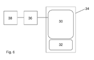
- FIG. 6 in the form of a block diagram, a main mirror 30 and an additional mirror 32 arranged in a common housing 34 arranged directly above one another.
- the main mirror 30 is adjustable by means of an electromotive main mirror adjustment device 36.
- the additional mirror 32 is rigidly connected in a certain position with the common housing 34.
- the adjusting device 36 is connected to a control device 38. In the control device 38 all possible adjustment positions of the main mirror 30 are stored digitized in a memory. For each of these possible positions, a value is stored whether this position is allowed or not.
- Whether the respective position is allowed or not depends on whether, when setting this respective position, there is a field of view gap between main mirror 20 and additional mirror 22 or not. If there is a field of view gap, this adjustment position is not allowed. If there is no field of view gap, this position is allowed.
- Fig. 7 schematically shows a third embodiment of the invention in an analogous representation to Fig. 6 that differs from the embodiment Fig. 6 only differs in that in addition an additional mirror adjustment device 37 is provided by means of which the additional mirror is adjustable.
- the additional-mirror adjusting device 37 is also connected to the control device 38.
- the control device 38 all possible positions W Hn of the main mirror 30 and all possible positions W Zm of the additional mirror 32 are stored in the form of a matrix, as shown in the table of FIG Fig. 8 is shown. Ie. the main mirror positions W Hn form the column designation and the additional mirror positions W Zm form the row designations of this matrix.
Landscapes
- Engineering & Computer Science (AREA)
- Multimedia (AREA)
- Mechanical Engineering (AREA)
- Rear-View Mirror Devices That Are Mounted On The Exterior Of The Vehicle (AREA)
- Mirrors, Picture Frames, Photograph Stands, And Related Fastening Devices (AREA)
Abstract
Description
- Die Erfindung betrifft einen Spiegelkopf gemäß dem Oberbegriff des Anspruchs 1 bzw. 5 sowie einen Außenspiegel mit einem solchen Spiegelkopf gemäß Anspruch 9.
- Aufgrund gesetzlicher Anforderungen für die Sichtfelder von Außenspiegeln an Nutzfahrzeugen sind häufig Hauptspiegel und wenigstens ein Zusatzspiegel mit unterschiedlichen Sichtfeldern in einem gemeinsamen Gehäuse angeordnet. Ein solcher Außenspiegel ist beispielsweise aus der
EP 1020327 B1 bekannt. - In aller Regel ist zumindest der Hauptspiegel manuell oder motorisch verstellbar. Aufgrund der Verstellbarkeit des Hauptspiegels kann es bei ungünstiger Einstellung des Hauptspiegels dazu kommen, dass sich zwischen dem Sichtfeld des Hauptspiegels und das Sichtfeld des Zusatzspiegels eine durch die beiden Spiegel nicht einsehbare Sichtfeldlücke ergibt. Da beide Spiegel unmittelbar nebeneinander angeordnet sind, geht ein Nutzer implizit davon aus, dass ein Objekt, dass im gemeinsamen Randbereich der beiden Spiegel aus dem Hauptspiegel verschwindet unmittelbar im benachbarten Zusatzspiegel auftaucht und umgekehrt. Dem Nutzer ist in der Regel nicht bewusst, dass aufgrund einer ungünstigen Stellung des Hauptspiegels in Relation zu dem Zusatzspiegel eine nicht einsehbare Sichtfeldlücke zwischen den Sichtfeldern des Hauptspiegels und des Zusatzspiel entstehen kann. Dem Nutzer ist also nicht bewusst, dass unter Umständen ein Hindernis in dieser Sichtfeldlücke für ihn nicht einsehbar ist. Dies gilt umso mehr, wenn zusätzlich auch der Zusatzspiegel motorisch oder manuell verstellbar ist.
- Aus der
DE-OS 2158258 DE 102007013028 B4 und derDE 3931485 A1 sind Außenspiegel mit sich zum Teil überlappenden Sichtfeldern bekannt. Nachteilig hierbei ist es, dass durch die starre Verbindung zwischen den Spiegelflächen mit den überlappenden Sichtfeldern keinerlei Variabilität und Anpassungsfähigkeit gegeben ist. - Ausgehend von der
DE-OS 2158258 - Die Lösung dieser Aufgaben erfolgt durch die Merkmale der Ansprüche 1, 5 bzw. 9.
- Dadurch, dass der Haupt- und der Zusatzspiegel über deren jeweiliges Gehäuse lösbar miteinander verbunden sind, wird zum einen bei Verstellung des Hauptspiegels automatisch der Zusatzspiegel mit verstellt und zusätzlich lassen sich unterschiedliche Haupt- und Zusatzspiegel auf einfache Weise miteinander kombinieren. Es ergibt sich somit ein modulares Spiegelsystem, in dem sich unterschiedliche Zusatzspiegel mit dem Hauptspiegel kombinieren lassen. Das Hauptspiegelgehäuse ist vorzugsweise so ausgestaltet, dass der Hauptspiegel auch ohne daran montierten Zusatzspiegel eingesetzt werden kann. Die Anordnung von Haupt- und Zusatzspiegel in ihrer starren Verbindung ist so gewählt, dass deren Sichtfelder sich überlappen oder unmittelbar aneinander angrenzen. Damit wird verhindert, dass im gemeinsamen Grenzbereich zwischen den beiden Spiegeln eine für den Nutzer nicht einsehbare Sichtfeldlücke entstehen kann.
- Die lösbare Verbindung zwischen Haupt- und Zusatzspiegel kann mittels Verschraubung erfolgen - Anspruch 2. Vorzugsweise erfolgt die Verbindung jedoch durch eine lösbare Formschlussverbindung - Anspruch 3 - und insbesondere durch eine Clips-Verbindung - Anspruch 4. Durch die lösbare Formschlussverbindung wird der Austausch des Zusatzspiegels vereinfacht.
- An Stelle einer mechanischen starren Verbindung von Haupt- und Zusatzspiegel ist es auch möglich, quasi eine elektronische Kopplung der Positionen von Haupt- und Zusatzspiegel zu erzwingen. In einer Steuereinrichtung, die mit der Verstelleinrichtung des Hauptspiegels verbunden ist, sind erlaubte und nicht erlaubte Positionen für den Hauptspiegel abgespeichert. Wenn der Hauptspiegel in eine Position verstellt werden soll, die nicht erlaubt ist, wird diese Verstellung nicht ausgeführt bzw. nur bis zu der Position ausgeführt, an der noch eine Sichtfeldüberlappung vorliegt oder die beiden Sichtfelder gerade aneinander angrenzen - Anspruch 5.
- In gleicher Weise werden in der Steuereinrichtung erlaubte und nicht erlaubte Positionen abgespeichert werden, wenn auch der Zusatzspiegel elektronisch bzw. elektromotorisch verstellbar ist - Anspruch 6.
- Weitere Einzelheiten, Merkmale und Vorteile der Erfindung ergeben sich aus der nachfolgenden Beschreibung bevorzugter Ausführungsformen anhand der Zeichnungen.
- Es zeigt:
-
Fig. 1 eine Aufsicht auf die Spiegelflächen ein ersten Ausführungsform der Erfindung mit einem Hauptspiegel und einem Zusatzspiegel; -
Fig. 2 eine Schnittdarstellung entlang der Linie A-A inFig. 1 ; -
Fig. 3 eine Rückansicht der ersten Ausführungsform; -
Fig. 4 eine schematische Darstellung der Sichtfelder von Haupt- und Zusatzspiegel; -
Fig. 5 eine perspektivische Darstellung einerzweiten Ausführungsform der Erfindung; -
Fig. 6 eine schematische Darstellung einer dritten Ausführungsform der Erfindung; -
Fig. 7 eine schematische Darstellung einer vierten Ausführungsform der Erfindung; -
Fig. 8 eine Tabelle zur Erläuterung einer vierten Ausführungsform der Erfindung. -
Fig. 1 bis 3 zeigen eine erste Ausführungsform eines erfindungsgemäßen Spiegelkopfes in Form eines Kopfverstellers. Der Spiegelkopf umfasst einen Hauptspiegel 2 mit einer trapezförmigen Hauptspiegelfläche 1 mit gerundeten Ecken sowie einen Zusatzspiegel 4 mit einer Zusatzspiegelscheibe 3, der sich unmittelbar an eine der schmalen Seiten des Hauptspiegels 2 anschließt. Der Hauptspiegel 2 ist in einem Gehäuse 6 und der Zusatzspiegel 4 in einem Gehäuse 7 angeordnet. Das Hauptspiegelgehäuse 6 ist mittels einer Schraubverbindung 5 starr mit dem Zusatzspiegelgehäuse verbunden. Zusatzspiegelscheibe 3 und Hauptspiegelscheibe 1 sind starr in ihren jeweiligen Gehäusen 6, 7 angeordnet. An das Gehäuse 6 des Hauptspiegels 2 greift eine elektromotorische Verstelleinrichtung 8 an und aufgrund der starren Verbindung zwischen Hauptspiegel 2 und Zusatzspiegel 4 wird bei Betätigung der Verstelleinrichtung 8 immer Hauptspiegel 2 und Zusatzspiegel 4 gemeinsame verstellt. - In
Fig. 4 ist schematisch in Aufsicht ein Traktor 10 dargestellt, der einen linken Außenspiegel 12 und einen rechten Außenspiegel 14 aufweist, die jeweils mit einem Spiegelkopf gemäß der ersten Ausführungsform der vorliegenden Erfindung versehen sind. Der Hauptspiegel 2 weist ein Hauptspiegelsichtfeld 16 und der Zusatzspiegel 4 weist ein Zusatzspiegelsichtfeld 18 auf. Die Größe und Lage dieser Sichtfelder 16, 18 ist inFig. 4 dargestellt. 16' bezeichnet das Sichtfeld, das in der Vergangenheit gesetzlich gefordert war, 16 bezeichnet das größere aktuell geforderte Sichtfeld eines Hauptspiegels. Die beiden Spiegel 2, 4 sind so miteinander verschraubt, dass sich die Sichtfelder 16, 18 der beiden Spiegel sich in einem Schnittbereich 17 überlappen, so dass keine uneinsehbare Sichtfeldlücke zwischen den Sichtfeldern 16 und 18 der beiden Spiegel 2, 4 vorliegt. -
Fig. 5 zeigt eine perspektivische Darstellung einer alternativen lösbaren Verbindung zwischen Haupt- und Zusatzspiegelgehäuse 6, 7 des in denFiguren 1 und 3 gezeigten Spiegelkopfes mittels Formschluss.Fig. 5 zeigt Haupt- und Zusatzspiegelgehäuse 6, 7 offen, d. h. ohne eingesetzte Haupt- und Zusatzspiegelscheibe 1, 3. Das im wesentlichen wannenförmige Hauptspiegelgehäuse 6 weist an an der Grenzwand 20 zu dem Zusatzspiegelgehäuse 7 mehrere Befestigungsschlitze 22 auf. Das Zusatzspiegelgehäuse 7 weist an seiner der Grenzwand 20 des Hauptspiegelgehäuses 6 zugewandten Seite Befestigungselemente 24 auf, die mittels Formschluss in die Befestigungsschlitze 22 eingreifen. Die Befestigungselemente 24 sind T-förmige Elemente mit einem Halsteil 26 und einem Querteil 28. Die Dicke des Halsteils 26 der Befestigungselemente entspricht in etwa der Breite der Befestigungsschlitze 22, so dass das Halsteil 26 in die Befestigungsschlitze 22 eingeführt werden kann. Das Querteil 28 verhindert ein Abziehen des Zusatzspiegelgehäuses 7 in Längsrichtung des Halsteils 26. Die nach Montage des Zusatzspiegelgehäuses 7 an dem Hauptspiegelgehäuse 6 eingesetzte Hauptspiegelscheibe 1 verhindert ein Abziehen des Zusatzspiegelgehäuses 7 in Längsrichtung der Befestigungsschlitze 22. - Anstelle der starren mechanischen Kopplung zwischen Haut- und Zusatzspiegel kann gemäß einer dritten Ausführungsform der Erfindung die Kopplung der beiden Spiegel auch elektronisch erfolgen. Hierzu ist
Fig. 6 in Form eines Blockschaltbildes ein Hauptspiegel 30 und ein Zusatzspiegel 32 in einem gemeinsamen Gehäuse 34 angeordnet unmittelbar übereinander angeordnet. Der Hauptspiegel 30 ist mittels einer elektromotorischen Hauptspiegel-Verstelleinrichtung 36 verstellbar. Der Zusatzspiegel 32 ist in einer bestimmten Lage starr mit dem gemeinsamen Gehäuse 34 verbunden. Die Verstelleinrichtung 36 ist mit einer Steuereinrichtung 38 verbunden. In der Steuereinrichtung 38 sind in einem Speicher alle möglichen Verstellpositionen des Hauptspiegels 30 digitalisiert abgespeichert. Zu jedem dieser möglichen Positionen ist ein Wert gespeichert, ob diese Position erlaubt ist oder nicht. Ob die jeweilige Position erlaubt ist oder nicht richtet sich danach, ob bei Einstellung dieser jeweiligen Position sich zwischen Hauptspiegel 20 und Zusatzspiegels 22 eine Sichtfeldlücke ergibt oder nicht. Ergibt sich eine Sichtfeldlücke, ist diese Verstellposition nicht erlaubt. Ergibt sich keine Sichtfeldlücke, ist diese Position erlaubt. -
Fig. 7 zeigt schematisch eine dritte Ausführungsform der Erfindung in analoger Darstellung zuFig. 6 , die sich von der Ausführungsform nachFig. 6 lediglich dadurch unterscheidet, dass zusätzlich eine Zusatzspiegel-Verstelleinrichtung 37 vorgesehen ist, mittels der der Zusatzspiegel verstellbar ist. Die Zusatzspiegel-Verstelleinrichtung 37 ist ebenfalls mit der Steuereinrichtung 38 verbunden. In der Steuereinrichtung 38 sind alle möglichen Positionen WHn des Hauptspiegels 30 und alle möglichen Positionen WZm des Zusatzspiegels 32 in Form einer Matrix abgespeichert, wie dies in der Tabelle vonFig. 8 dargestellt ist. D. h. die Hauptspiegelpositionen WHn bilden die Spaltenbenennung und die Zusatzspiegelpositionen WZm bilden die Zeilenbenennungen dieser Matrix. In den einzelnen Zellen dieser Matrix ist lediglich vermerkt, ob die jeweilige Positionskombination WHi/ WZj zulässig ist - ok - oder nicht - x -. Wiederum ist eine Position der beiden Spiegel erlaubt, wenn sich für den gemeinsamen Grenzbereich keine Sichtfeldlücke ergibt. Nicht erlaubt ist die Position, wenn sich eine Sichtfeldlücke ergibt. -
- 1
- Hauptspiegelscheibe
- 2
- Hauptspiegel
- 3
- Zusatzspiegelscheibe
- 4
- Zusatzspiegel
- 5
- Schraubverbindung
- 6
- Gehäuse Hauptspiegel
- 7
- Gehäuse Zusatzspiegel
- 8
- gemeinsame Verstelleinrichtung
- 10
- Traktor
- 12
- linker Außenspiegel
- 14
- rechter Außenspiegel
- 16
- Sichtfeld Hauptspiegel (aktuell)
- 16'
- Sichtfeld Hauptspiegel (Vergangenheit)
- 17
- Überlappbereich
- 18
- Sichtfeld Zusatzspiegel
- 20
- Grenzwand
- 22
- Befestigungsschlitze
- 24
- Befestigungselemente
- 26
- Halsteil von 24
- 28
- Querteil von 24
- 30
- Hauptspiegel
- 32
- Zusatzspiegel
- 34
- gemeinsames Gehäuse
- 36
- Hauptspiegel -Verstelleinrichtung
- 37
- Zusatzspiegel -Verstelleinrichtung
- 38
- Steuereinrichtung
Claims (9)
- Spiegelkopf, mit
einem verstellbaren Hauptspiegel (2; ), der eine Hauptspiegelscheibe (1) und ein Hauptspiegelgehäuse (6) umfasst,
wenigstens einem Zusatzspiegel (4), der eine Zusatzspiegelscheibe (3) und eine Zusatzspiegelgehäuse (7) umfasst,
wobei Haupt- und Zusatzspiegel unmittelbar neben- oder übereinander angeordnet sind, und wobei der Hauptspiegel (2) ein Hauptspiegelsichtfeld (16) und der Zusatzspiegel (4) ein Zusatzspiegelsichtfeld (18) aufweist, und
einer Spiegelverstelleinrichtung (8) zur Verstellung des Hauptspiegels, dadurch gekennzeichnet,
dass das Hauptspiegelgehäuse (6) und das Zusatzspiegelgehäuse (7) des wenigstens einen Zusatzspiegels (4; ) derart starr miteinander verbunden sind, dass die Sichtfelder (16, 18) von Haupt- und Zusatzspiegel unmittelbar aneinander angrenzend sind oder in einem Teilbereich (17) überlappen, und
dass Haupt- und Zusatzspiegel (2, 4) lösbar miteinander verbunden sind. - Spiegelkopf nach Anspruch 1, dadurch gekennzeichnet, dass die Gehäuse (6, 7) von Haupt- und Zusatzspiegel miteinander verschraubt sind.
- Spiegelkopf nach Anspruch 1 oder 2, dadurch gekennzeichnet, dass Haupt- (2) und Zusatzspiegel (4) über eine lösbare Formschlussverbindung (22, 24) miteinander verbunden sind.
- Spiegelkopf nach einem der vorhergehenden Ansprüche, dadurch gekennzeichnet, dass Haupt- und Zusatzspiegel über eine lösbare Clips-Verbindung miteinander verbunden sind.
- Spiegelkopf, mit
einem verstellbaren Hauptspiegel (30) und wenigstens einem Zusatzspiegel (32), die unmittelbar neben- oder übereinander angeordnet sind, wobei der Hauptspiegel (30) ein Hauptspiegelsichtfeld (16) und der Zusatzspiegel (32) ein Zusatzspiegelsichtfeld (18) aufweist, und einer Verstelleinrichtung (36) zur Verstellung des Hauptspiegels (30) gekennzeichnet durch
eine Steuereinrichtung (38), die mit der Hauptspiegel-Verstelleinrichtung (36) verbunden ist und die eine Verstellung der des Hauptspiegels (30) nur derart zulässt, dass die Sichtfelder (16, 18) von dem Hauptspiegel (30) und dem wenigstens einen Zusatzspiegel (32) unmittelbar aneinander angrenzend sind oder in einem Teilbereich (17) überlappen. - Spiegelkopf nach Anspruch 5, dadurch gekennzeichnet, dass der wenigstens eine Zusatzspiegel (32) mittels wenigstens einer Zusatzspiegel-Verstelleinrichtung (37) verstellbar ist, und dass die Steuereinrichtung (38) eine Verstellung der Spiegel (30, 32) nur derart zulässt, dass deren Sichtfelder (16, 18) unmittelbar aneinander angrenzend sind oder in einem Teilbereich (17) überlappen.
- Spiegelkopf nach einem der vorhergehenden Ansprüche, dadurch gekennzeichnet, dass der Hauptspiegel (2; 30) und der wenigstens eine Zusatzspiegel (4; 32) unterschiedliche Wölbungsradien aufweisen.
- Spiegelkopf nach einem der vorhergehenden Ansprüche, dadurch gekennzeichnet, dass der Hauptspiegel (2; 30) und/oder der wenigstens eine Zusatzspiegel (4; 32) ein asphärischer Spiegel ist.
- Außenspiegel für Kraft- und Nutzfahrzeuge mit einem Spiegelkopf nach einem der vorhergehenden Ansprüche.
Priority Applications (1)
| Application Number | Priority Date | Filing Date | Title |
|---|---|---|---|
| PL10188300T PL2316693T3 (pl) | 2009-10-29 | 2010-10-21 | Głowica lusterka z zachodzącym polem widzenia |
Applications Claiming Priority (1)
| Application Number | Priority Date | Filing Date | Title |
|---|---|---|---|
| DE102009046174A DE102009046174A1 (de) | 2009-10-29 | 2009-10-29 | Spiegelkopf mit überlappendem Sichtfeld |
Publications (2)
| Publication Number | Publication Date |
|---|---|
| EP2316693A1 true EP2316693A1 (de) | 2011-05-04 |
| EP2316693B1 EP2316693B1 (de) | 2013-03-27 |
Family
ID=41694253
Family Applications (1)
| Application Number | Title | Priority Date | Filing Date |
|---|---|---|---|
| EP10188300A Active EP2316693B1 (de) | 2009-10-29 | 2010-10-21 | Spiegelkopf mit überlappendem Sichtfeld |
Country Status (9)
| Country | Link |
|---|---|
| US (1) | US20110102923A1 (de) |
| EP (1) | EP2316693B1 (de) |
| JP (1) | JP2011093522A (de) |
| CN (1) | CN102085829B (de) |
| BR (1) | BRPI1004163B1 (de) |
| DE (2) | DE102009046174A1 (de) |
| EA (1) | EA201001562A1 (de) |
| ES (1) | ES2404357T3 (de) |
| PL (1) | PL2316693T3 (de) |
Families Citing this family (4)
| Publication number | Priority date | Publication date | Assignee | Title |
|---|---|---|---|---|
| DE102014214128B4 (de) * | 2014-07-21 | 2016-02-04 | Mekra Lang Gmbh & Co. Kg | Trägervorrichtung für die Befestigung einer bildgebenden Einrichtung eines indirekten Sichtsystems an einem Fahrzeug sowie indirektes Sichtsystem hiermit |
| GB2539471B (en) * | 2015-06-17 | 2018-06-27 | Ford Global Tech Llc | A method for adjusting a mirror |
| DE102016105668A1 (de) † | 2016-03-29 | 2017-10-05 | Ficosa International Gmbh | Fahrzeugspiegel und Verfahren zu dessen Herstellung |
| CN110753190B (zh) * | 2019-11-22 | 2025-04-25 | 北京星岩未来传媒有限公司 | 一种用于智能移动设备的双角度采集附加镜头 |
Citations (10)
| Publication number | Priority date | Publication date | Assignee | Title |
|---|---|---|---|---|
| DE2158258A1 (de) | 1971-11-24 | 1973-05-30 | Jack Donaldson | Rueckspiegel |
| US3826563A (en) * | 1972-03-27 | 1974-07-30 | B Davis | Side view mirror attachment for motor vehicle |
| DE2537876A1 (de) * | 1975-08-26 | 1977-03-03 | Reitter & Schefenacker Kg | Rueckblickspiegelanordnung fuer fahrzeuge, insbesondere kraftfahrzeuge |
| US4678294A (en) * | 1985-12-03 | 1987-07-07 | Nostrand Willard R Van | Mirror assembly for determining distance to passed vehicle |
| DE3931485A1 (de) | 1989-09-21 | 1991-04-04 | Seefluth Uwe Christian | Aussenrueckspiegel fuer kraftfahrzeuge |
| DE4132962C1 (en) * | 1991-10-04 | 1992-10-29 | Metallwarenfabrik Wilke Gmbh & Co Kg, 3340 Wolfenbuettel, De | External car rear view mirror - has holder and first housing part with identical connectors on facing sides for selective fitting |
| US5210655A (en) * | 1992-02-10 | 1993-05-11 | Mishali Moti M | Multi-vision mirror for a rearview mirror in a motor vehicle |
| US20010000443A1 (en) * | 1994-11-14 | 2001-04-26 | Galicia Joseph R. | Side rear view mirror for a vehicle |
| EP1020327B1 (de) | 1999-01-13 | 2004-06-09 | MEKRA Lang GmbH & Co. KG | Hornförmige Rückblickspiegelanordnung für Nutzfahrzeuge, insbesondere für Omnibusse |
| DE102007013028B4 (de) | 2007-03-19 | 2009-04-09 | Mekra Lang Gmbh & Co. Kg | Außenspiegelanordnung für Kraftfahrzeuge |
Family Cites Families (25)
| Publication number | Priority date | Publication date | Assignee | Title |
|---|---|---|---|---|
| JPS5456838U (de) * | 1977-09-29 | 1979-04-19 | ||
| JPS5555447U (de) * | 1978-10-11 | 1980-04-15 | ||
| JPS5825251U (ja) * | 1981-08-12 | 1983-02-17 | 西 伯士 | 自動車のサイドバツクミラ− |
| JPH0323876Y2 (de) * | 1985-03-23 | 1991-05-24 | ||
| DE3600869A1 (de) * | 1986-01-10 | 1987-07-16 | Miroslaw Janowicz | Aussenspiegel fuer lastkraftwagen od.dgl. |
| JPS63119444U (de) * | 1987-01-30 | 1988-08-02 | ||
| BR8900142A (pt) * | 1989-01-10 | 1990-08-14 | Metagal Industria E Comercio Ltda. | Aperfeicoamentos em espelho retrovisor externo para veiculos |
| JP2564822Y2 (ja) * | 1992-11-06 | 1998-03-11 | 市光工業株式会社 | 自動車用補助ミラーの取付構造 |
| JP3006816U (ja) * | 1993-07-16 | 1995-01-31 | ブー ブュン ジュン | 前・後方観察機能を有する自動車用ミラー |
| JPH0722849U (ja) * | 1993-08-19 | 1995-04-25 | 貴典 長坂 | 車両用補助ミラー及びこの補助ミラーを用いたサイドミラー |
| US5500766A (en) * | 1995-05-04 | 1996-03-19 | Stonecypher; Bob | Blind spot side mirror |
| CN2237572Y (zh) * | 1995-07-12 | 1996-10-16 | 梁庆杉 | 汽车后视镜的广角辅助镜 |
| US6962422B1 (en) * | 1996-01-16 | 2005-11-08 | Roscoe, Inc. | Single shell, double view mirror for vehicles |
| US6126289A (en) * | 1996-05-20 | 2000-10-03 | Nagayama; Koukichi | Wide angle mirror attachable to an existing rear view mirror |
| US5796176A (en) * | 1996-07-11 | 1998-08-18 | Donnelly Corporation | Memory mirror system for vehicles |
| US6511192B1 (en) * | 1999-12-17 | 2003-01-28 | Britax Vision Systems (North America) Inc. | Side view mirror with integral lighting |
| US6536908B2 (en) * | 2001-06-20 | 2003-03-25 | Janchy Enterprise Co., Ltd. | Car rearview mirror structure |
| KR100858406B1 (ko) * | 2001-10-30 | 2008-09-11 | 쉐프네커 비젼 시스템즈 오스트레일리아 프로프라이어터리 리미티드 | 파워 텔레스코핑 차량 미러 조립체 |
| EP1393974A1 (de) * | 2002-08-29 | 2004-03-03 | MEKRA Lang GmbH & Co. KG | Aussenrückspiegelaufbau für Nutzfahrzeuge |
| JP3781714B2 (ja) * | 2002-11-01 | 2006-05-31 | 株式会社アトラスオート | ドアミラー |
| JP2005059822A (ja) * | 2002-12-20 | 2005-03-10 | Murakami Corp | アウターミラー |
| JP2004196224A (ja) * | 2002-12-20 | 2004-07-15 | Murakami Corp | アウターミラー |
| US20060181790A1 (en) * | 2005-02-17 | 2006-08-17 | Jones Harry C Iii | Rearview mirror system |
| JP2006232150A (ja) * | 2005-02-25 | 2006-09-07 | Ichikoh Ind Ltd | 車両用アウトサイドミラー装置 |
| US7857469B2 (en) * | 2008-01-03 | 2010-12-28 | Smr Patents S.A.R.L. | Exterior rearview mirror for motor vehicles |
-
2009
- 2009-10-29 DE DE102009046174A patent/DE102009046174A1/de not_active Ceased
- 2009-11-06 DE DE202009015138U patent/DE202009015138U1/de not_active Expired - Lifetime
-
2010
- 2010-10-21 ES ES10188300T patent/ES2404357T3/es active Active
- 2010-10-21 EP EP10188300A patent/EP2316693B1/de active Active
- 2010-10-21 PL PL10188300T patent/PL2316693T3/pl unknown
- 2010-10-28 US US12/913,930 patent/US20110102923A1/en not_active Abandoned
- 2010-10-28 BR BRPI1004163-0A patent/BRPI1004163B1/pt active IP Right Grant
- 2010-10-28 EA EA201001562A patent/EA201001562A1/ru unknown
- 2010-10-28 JP JP2010241858A patent/JP2011093522A/ja not_active Withdrawn
- 2010-10-29 CN CN201010600627.2A patent/CN102085829B/zh active Active
Patent Citations (10)
| Publication number | Priority date | Publication date | Assignee | Title |
|---|---|---|---|---|
| DE2158258A1 (de) | 1971-11-24 | 1973-05-30 | Jack Donaldson | Rueckspiegel |
| US3826563A (en) * | 1972-03-27 | 1974-07-30 | B Davis | Side view mirror attachment for motor vehicle |
| DE2537876A1 (de) * | 1975-08-26 | 1977-03-03 | Reitter & Schefenacker Kg | Rueckblickspiegelanordnung fuer fahrzeuge, insbesondere kraftfahrzeuge |
| US4678294A (en) * | 1985-12-03 | 1987-07-07 | Nostrand Willard R Van | Mirror assembly for determining distance to passed vehicle |
| DE3931485A1 (de) | 1989-09-21 | 1991-04-04 | Seefluth Uwe Christian | Aussenrueckspiegel fuer kraftfahrzeuge |
| DE4132962C1 (en) * | 1991-10-04 | 1992-10-29 | Metallwarenfabrik Wilke Gmbh & Co Kg, 3340 Wolfenbuettel, De | External car rear view mirror - has holder and first housing part with identical connectors on facing sides for selective fitting |
| US5210655A (en) * | 1992-02-10 | 1993-05-11 | Mishali Moti M | Multi-vision mirror for a rearview mirror in a motor vehicle |
| US20010000443A1 (en) * | 1994-11-14 | 2001-04-26 | Galicia Joseph R. | Side rear view mirror for a vehicle |
| EP1020327B1 (de) | 1999-01-13 | 2004-06-09 | MEKRA Lang GmbH & Co. KG | Hornförmige Rückblickspiegelanordnung für Nutzfahrzeuge, insbesondere für Omnibusse |
| DE102007013028B4 (de) | 2007-03-19 | 2009-04-09 | Mekra Lang Gmbh & Co. Kg | Außenspiegelanordnung für Kraftfahrzeuge |
Also Published As
| Publication number | Publication date |
|---|---|
| DE102009046174A1 (de) | 2011-05-05 |
| CN102085829B (zh) | 2017-04-26 |
| US20110102923A1 (en) | 2011-05-05 |
| ES2404357T3 (es) | 2013-05-27 |
| PL2316693T3 (pl) | 2013-08-30 |
| BRPI1004163A2 (pt) | 2013-02-26 |
| EP2316693B1 (de) | 2013-03-27 |
| DE202009015138U1 (de) | 2010-02-18 |
| JP2011093522A (ja) | 2011-05-12 |
| BRPI1004163B1 (pt) | 2019-11-12 |
| CN102085829A (zh) | 2011-06-08 |
| EA201001562A1 (ru) | 2011-06-30 |
Similar Documents
| Publication | Publication Date | Title |
|---|---|---|
| EP2269909B1 (de) | Vorrichtung zum Festlegen von Gegenständen | |
| DE102007019539A1 (de) | Luftzufuhrvorrichtung für die Klimatisierung von Passagierräumen in Flugzeugen | |
| DE69719691T2 (de) | Befestigung für Aussenhautteile einer Fahrzeugkarosserie | |
| DE102007013904A1 (de) | Spaltabdeckvorrichtung | |
| EP2316693A1 (de) | Spiegelkopf mit überlappendem Sichtfeld | |
| EP1977927A2 (de) | Fahrzeugsitz | |
| EP2315681B1 (de) | Sitzanordnung | |
| DE102007056168B4 (de) | Anordnung zum Verkleiden von Fahrzeuginnenräumen | |
| DE19919256A1 (de) | Halterung für einen Scheinwerfer eines Fahrzeuges | |
| DE102017110654B4 (de) | Fahrzeugsitz und kopfstütze mit dynamischem aufprallenergieverwaltungssystem | |
| EP3110666B1 (de) | Befestigungsanordnung einer kühlerverkleidung und eines stossfängers an einem frontendträger eines kraftwagens | |
| DE102013213822B4 (de) | Bauteilanordnung für ein Lenkrad | |
| DE102018120708B4 (de) | System zum Verbinden eines Befestigungsprofils für eine Sitzvorrichtung eines Fahrzeuges mit einem Halteelement eines Fahrzeugbodens | |
| EP2273638A2 (de) | Klammer für Kabelkanäle zur Kaschierung von Schnittkanten | |
| DE102018107555B4 (de) | Tragrahmenquerstrukturanordnung eines Kraftfahrzeugs | |
| DE602004006073T2 (de) | Armaturenbrett-Überdeckung für Kraftfahrzeuge | |
| EP1651835B1 (de) | Getriebe-antriebseinheit | |
| EP4051559B1 (de) | Baukastensystem und verbindungseinrichtung für kraftfahrzeug-luftleitelemente | |
| EP4275963B1 (de) | Kraftfahrzeug-seitenwandkonstruktion, seitenwandelemente für eine kraftfahrzeug-seitenwandkonstruktion sowie montageverfahren | |
| DE102009029850B4 (de) | Klemmvorrichtung zum Ausgleich einer entgegengesetzten Abweichung in einem dreigeteilten Verkleidungsaufbau | |
| DE102020112235B3 (de) | Montageeinheit für einen Antrieb einer Spoilervorrichtung eines Fahrzeugs | |
| DE102019103456B4 (de) | Versteifungsbauteil für eine lokale Versteifung einer Tragstruktur eines Fahrzeugs | |
| DE102010056065A1 (de) | Montageträger | |
| DE102010052960A1 (de) | Kraftfahrzeug mit einer bodenseitigen Befestigungsanordnung zur Befestigung eines Fahrzeugsitzes | |
| EP4091932A1 (de) | Befestigungssystem zur befestigung von verkleidungselementen in einem flugzeug, insbesondere von seitenwand- und dado-paneelen |
Legal Events
| Date | Code | Title | Description |
|---|---|---|---|
| PUAI | Public reference made under article 153(3) epc to a published international application that has entered the european phase |
Free format text: ORIGINAL CODE: 0009012 |
|
| AK | Designated contracting states |
Kind code of ref document: A1 Designated state(s): AL AT BE BG CH CY CZ DE DK EE ES FI FR GB GR HR HU IE IS IT LI LT LU LV MC MK MT NL NO PL PT RO RS SE SI SK SM TR |
|
| AX | Request for extension of the european patent |
Extension state: BA ME |
|
| 17P | Request for examination filed |
Effective date: 20110808 |
|
| GRAP | Despatch of communication of intention to grant a patent |
Free format text: ORIGINAL CODE: EPIDOSNIGR1 |
|
| GRAS | Grant fee paid |
Free format text: ORIGINAL CODE: EPIDOSNIGR3 |
|
| GRAA | (expected) grant |
Free format text: ORIGINAL CODE: 0009210 |
|
| AK | Designated contracting states |
Kind code of ref document: B1 Designated state(s): AL AT BE BG CH CY CZ DE DK EE ES FI FR GB GR HR HU IE IS IT LI LT LU LV MC MK MT NL NO PL PT RO RS SE SI SK SM TR |
|
| REG | Reference to a national code |
Ref country code: GB Ref legal event code: FG4D Free format text: NOT ENGLISH |
|
| REG | Reference to a national code |
Ref country code: CH Ref legal event code: EP |
|
| REG | Reference to a national code |
Ref country code: AT Ref legal event code: REF Ref document number: 603163 Country of ref document: AT Kind code of ref document: T Effective date: 20130415 |
|
| REG | Reference to a national code |
Ref country code: SE Ref legal event code: TRGR |
|
| REG | Reference to a national code |
Ref country code: IE Ref legal event code: FG4D Free format text: LANGUAGE OF EP DOCUMENT: GERMAN |
|
| REG | Reference to a national code |
Ref country code: DE Ref legal event code: R096 Ref document number: 502010002697 Country of ref document: DE Effective date: 20130523 |
|
| REG | Reference to a national code |
Ref country code: ES Ref legal event code: FG2A Ref document number: 2404357 Country of ref document: ES Kind code of ref document: T3 Effective date: 20130527 |
|
| PG25 | Lapsed in a contracting state [announced via postgrant information from national office to epo] |
Ref country code: NO Free format text: LAPSE BECAUSE OF FAILURE TO SUBMIT A TRANSLATION OF THE DESCRIPTION OR TO PAY THE FEE WITHIN THE PRESCRIBED TIME-LIMIT Effective date: 20130627 Ref country code: BG Free format text: LAPSE BECAUSE OF FAILURE TO SUBMIT A TRANSLATION OF THE DESCRIPTION OR TO PAY THE FEE WITHIN THE PRESCRIBED TIME-LIMIT Effective date: 20130627 Ref country code: LT Free format text: LAPSE BECAUSE OF FAILURE TO SUBMIT A TRANSLATION OF THE DESCRIPTION OR TO PAY THE FEE WITHIN THE PRESCRIBED TIME-LIMIT Effective date: 20130327 |
|
| REG | Reference to a national code |
Ref country code: LT Ref legal event code: MG4D |
|
| PG25 | Lapsed in a contracting state [announced via postgrant information from national office to epo] |
Ref country code: LV Free format text: LAPSE BECAUSE OF FAILURE TO SUBMIT A TRANSLATION OF THE DESCRIPTION OR TO PAY THE FEE WITHIN THE PRESCRIBED TIME-LIMIT Effective date: 20130327 Ref country code: GR Free format text: LAPSE BECAUSE OF FAILURE TO SUBMIT A TRANSLATION OF THE DESCRIPTION OR TO PAY THE FEE WITHIN THE PRESCRIBED TIME-LIMIT Effective date: 20130628 Ref country code: SI Free format text: LAPSE BECAUSE OF FAILURE TO SUBMIT A TRANSLATION OF THE DESCRIPTION OR TO PAY THE FEE WITHIN THE PRESCRIBED TIME-LIMIT Effective date: 20130327 |
|
| REG | Reference to a national code |
Ref country code: PL Ref legal event code: T3 |
|
| REG | Reference to a national code |
Ref country code: NL Ref legal event code: VDEP Effective date: 20130327 |
|
| PG25 | Lapsed in a contracting state [announced via postgrant information from national office to epo] |
Ref country code: HR Free format text: LAPSE BECAUSE OF FAILURE TO SUBMIT A TRANSLATION OF THE DESCRIPTION OR TO PAY THE FEE WITHIN THE PRESCRIBED TIME-LIMIT Effective date: 20130327 |
|
| PG25 | Lapsed in a contracting state [announced via postgrant information from national office to epo] |
Ref country code: PT Free format text: LAPSE BECAUSE OF FAILURE TO SUBMIT A TRANSLATION OF THE DESCRIPTION OR TO PAY THE FEE WITHIN THE PRESCRIBED TIME-LIMIT Effective date: 20130729 Ref country code: EE Free format text: LAPSE BECAUSE OF FAILURE TO SUBMIT A TRANSLATION OF THE DESCRIPTION OR TO PAY THE FEE WITHIN THE PRESCRIBED TIME-LIMIT Effective date: 20130327 Ref country code: CZ Free format text: LAPSE BECAUSE OF FAILURE TO SUBMIT A TRANSLATION OF THE DESCRIPTION OR TO PAY THE FEE WITHIN THE PRESCRIBED TIME-LIMIT Effective date: 20130327 Ref country code: RO Free format text: LAPSE BECAUSE OF FAILURE TO SUBMIT A TRANSLATION OF THE DESCRIPTION OR TO PAY THE FEE WITHIN THE PRESCRIBED TIME-LIMIT Effective date: 20130327 Ref country code: SK Free format text: LAPSE BECAUSE OF FAILURE TO SUBMIT A TRANSLATION OF THE DESCRIPTION OR TO PAY THE FEE WITHIN THE PRESCRIBED TIME-LIMIT Effective date: 20130327 Ref country code: NL Free format text: LAPSE BECAUSE OF FAILURE TO SUBMIT A TRANSLATION OF THE DESCRIPTION OR TO PAY THE FEE WITHIN THE PRESCRIBED TIME-LIMIT Effective date: 20130327 Ref country code: IS Free format text: LAPSE BECAUSE OF FAILURE TO SUBMIT A TRANSLATION OF THE DESCRIPTION OR TO PAY THE FEE WITHIN THE PRESCRIBED TIME-LIMIT Effective date: 20130727 |
|
| PG25 | Lapsed in a contracting state [announced via postgrant information from national office to epo] |
Ref country code: CY Free format text: LAPSE BECAUSE OF FAILURE TO SUBMIT A TRANSLATION OF THE DESCRIPTION OR TO PAY THE FEE WITHIN THE PRESCRIBED TIME-LIMIT Effective date: 20130327 |
|
| PG25 | Lapsed in a contracting state [announced via postgrant information from national office to epo] |
Ref country code: DK Free format text: LAPSE BECAUSE OF FAILURE TO SUBMIT A TRANSLATION OF THE DESCRIPTION OR TO PAY THE FEE WITHIN THE PRESCRIBED TIME-LIMIT Effective date: 20130327 |
|
| PLBE | No opposition filed within time limit |
Free format text: ORIGINAL CODE: 0009261 |
|
| STAA | Information on the status of an ep patent application or granted ep patent |
Free format text: STATUS: NO OPPOSITION FILED WITHIN TIME LIMIT |
|
| 26N | No opposition filed |
Effective date: 20140103 |
|
| REG | Reference to a national code |
Ref country code: DE Ref legal event code: R097 Ref document number: 502010002697 Country of ref document: DE Effective date: 20140103 |
|
| BERE | Be: lapsed |
Owner name: MEKRA LANG G.M.B.H. & CO. KG Effective date: 20131031 |
|
| PG25 | Lapsed in a contracting state [announced via postgrant information from national office to epo] |
Ref country code: MC Free format text: LAPSE BECAUSE OF FAILURE TO SUBMIT A TRANSLATION OF THE DESCRIPTION OR TO PAY THE FEE WITHIN THE PRESCRIBED TIME-LIMIT Effective date: 20130327 |
|
| REG | Reference to a national code |
Ref country code: IE Ref legal event code: MM4A |
|
| PG25 | Lapsed in a contracting state [announced via postgrant information from national office to epo] |
Ref country code: BE Free format text: LAPSE BECAUSE OF NON-PAYMENT OF DUE FEES Effective date: 20131031 |
|
| PG25 | Lapsed in a contracting state [announced via postgrant information from national office to epo] |
Ref country code: IE Free format text: LAPSE BECAUSE OF NON-PAYMENT OF DUE FEES Effective date: 20131021 |
|
| PG25 | Lapsed in a contracting state [announced via postgrant information from national office to epo] |
Ref country code: SM Free format text: LAPSE BECAUSE OF FAILURE TO SUBMIT A TRANSLATION OF THE DESCRIPTION OR TO PAY THE FEE WITHIN THE PRESCRIBED TIME-LIMIT Effective date: 20130327 |
|
| REG | Reference to a national code |
Ref country code: CH Ref legal event code: PL |
|
| PG25 | Lapsed in a contracting state [announced via postgrant information from national office to epo] |
Ref country code: MK Free format text: LAPSE BECAUSE OF FAILURE TO SUBMIT A TRANSLATION OF THE DESCRIPTION OR TO PAY THE FEE WITHIN THE PRESCRIBED TIME-LIMIT Effective date: 20130327 Ref country code: HU Free format text: LAPSE BECAUSE OF FAILURE TO SUBMIT A TRANSLATION OF THE DESCRIPTION OR TO PAY THE FEE WITHIN THE PRESCRIBED TIME-LIMIT; INVALID AB INITIO Effective date: 20101021 Ref country code: CH Free format text: LAPSE BECAUSE OF NON-PAYMENT OF DUE FEES Effective date: 20141031 Ref country code: RS Free format text: LAPSE BECAUSE OF FAILURE TO SUBMIT A TRANSLATION OF THE DESCRIPTION OR TO PAY THE FEE WITHIN THE PRESCRIBED TIME-LIMIT Effective date: 20130627 Ref country code: LU Free format text: LAPSE BECAUSE OF NON-PAYMENT OF DUE FEES Effective date: 20131021 Ref country code: LI Free format text: LAPSE BECAUSE OF NON-PAYMENT OF DUE FEES Effective date: 20141031 |
|
| PG25 | Lapsed in a contracting state [announced via postgrant information from national office to epo] |
Ref country code: MT Free format text: LAPSE BECAUSE OF FAILURE TO SUBMIT A TRANSLATION OF THE DESCRIPTION OR TO PAY THE FEE WITHIN THE PRESCRIBED TIME-LIMIT Effective date: 20130327 |
|
| REG | Reference to a national code |
Ref country code: FR Ref legal event code: PLFP Year of fee payment: 6 |
|
| REG | Reference to a national code |
Ref country code: FR Ref legal event code: PLFP Year of fee payment: 7 |
|
| REG | Reference to a national code |
Ref country code: AT Ref legal event code: MM01 Ref document number: 603163 Country of ref document: AT Kind code of ref document: T Effective date: 20151021 |
|
| PG25 | Lapsed in a contracting state [announced via postgrant information from national office to epo] |
Ref country code: AT Free format text: LAPSE BECAUSE OF NON-PAYMENT OF DUE FEES Effective date: 20151021 |
|
| REG | Reference to a national code |
Ref country code: FR Ref legal event code: PLFP Year of fee payment: 8 |
|
| REG | Reference to a national code |
Ref country code: FR Ref legal event code: PLFP Year of fee payment: 9 |
|
| PG25 | Lapsed in a contracting state [announced via postgrant information from national office to epo] |
Ref country code: AL Free format text: LAPSE BECAUSE OF FAILURE TO SUBMIT A TRANSLATION OF THE DESCRIPTION OR TO PAY THE FEE WITHIN THE PRESCRIBED TIME-LIMIT Effective date: 20130327 |
|
| P01 | Opt-out of the competence of the unified patent court (upc) registered |
Effective date: 20230510 |
|
| PGFP | Annual fee paid to national office [announced via postgrant information from national office to epo] |
Ref country code: PL Payment date: 20230921 Year of fee payment: 14 |
|
| PGFP | Annual fee paid to national office [announced via postgrant information from national office to epo] |
Ref country code: DE Payment date: 20251009 Year of fee payment: 16 |
|
| PGFP | Annual fee paid to national office [announced via postgrant information from national office to epo] |
Ref country code: GB Payment date: 20251024 Year of fee payment: 16 |
|
| PGFP | Annual fee paid to national office [announced via postgrant information from national office to epo] |
Ref country code: FI Payment date: 20251022 Year of fee payment: 16 Ref country code: IT Payment date: 20251031 Year of fee payment: 16 |
|
| PGFP | Annual fee paid to national office [announced via postgrant information from national office to epo] |
Ref country code: FR Payment date: 20251029 Year of fee payment: 16 |
|
| PGFP | Annual fee paid to national office [announced via postgrant information from national office to epo] |
Ref country code: TR Payment date: 20251017 Year of fee payment: 16 |
|
| PGFP | Annual fee paid to national office [announced via postgrant information from national office to epo] |
Ref country code: SE Payment date: 20251023 Year of fee payment: 16 |
|
| PGFP | Annual fee paid to national office [announced via postgrant information from national office to epo] |
Ref country code: ES Payment date: 20251114 Year of fee payment: 16 |
|
| PG25 | Lapsed in a contracting state [announced via postgrant information from national office to epo] |
Ref country code: PL Free format text: LAPSE BECAUSE OF NON-PAYMENT OF DUE FEES Effective date: 20241021 |