EP2314985A1 - Optical tomographic image generating apparatus and optical tomographic image generating method - Google Patents
Optical tomographic image generating apparatus and optical tomographic image generating method Download PDFInfo
- Publication number
- EP2314985A1 EP2314985A1 EP10188406A EP10188406A EP2314985A1 EP 2314985 A1 EP2314985 A1 EP 2314985A1 EP 10188406 A EP10188406 A EP 10188406A EP 10188406 A EP10188406 A EP 10188406A EP 2314985 A1 EP2314985 A1 EP 2314985A1
- Authority
- EP
- European Patent Office
- Prior art keywords
- frames
- tomographic image
- synthesizing
- complex number
- image generating
- Prior art date
- Legal status (The legal status is an assumption and is not a legal conclusion. Google has not performed a legal analysis and makes no representation as to the accuracy of the status listed.)
- Withdrawn
Links
- 230000003287 optical effect Effects 0.000 title claims abstract description 33
- 238000000034 method Methods 0.000 title claims abstract description 24
- 230000002194 synthesizing effect Effects 0.000 claims abstract description 34
- 230000009466 transformation Effects 0.000 claims abstract description 10
- 238000006073 displacement reaction Methods 0.000 claims description 32
- 238000012935 Averaging Methods 0.000 claims description 9
- 238000004590 computer program Methods 0.000 claims description 4
- 230000015572 biosynthetic process Effects 0.000 claims description 2
- 238000003786 synthesis reaction Methods 0.000 claims 1
- 238000003384 imaging method Methods 0.000 abstract description 10
- 238000012545 processing Methods 0.000 description 18
- 238000006243 chemical reaction Methods 0.000 description 17
- 238000012014 optical coherence tomography Methods 0.000 description 10
- 230000014509 gene expression Effects 0.000 description 9
- 210000001525 retina Anatomy 0.000 description 9
- 238000010586 diagram Methods 0.000 description 7
- 238000005259 measurement Methods 0.000 description 7
- 239000006185 dispersion Substances 0.000 description 6
- 239000000835 fiber Substances 0.000 description 6
- 230000006870 function Effects 0.000 description 5
- 239000011521 glass Substances 0.000 description 5
- 230000007246 mechanism Effects 0.000 description 4
- 230000008569 process Effects 0.000 description 3
- 238000004364 calculation method Methods 0.000 description 2
- 210000004087 cornea Anatomy 0.000 description 2
- 230000000694 effects Effects 0.000 description 2
- 206010025421 Macule Diseases 0.000 description 1
- 238000007796 conventional method Methods 0.000 description 1
- 238000013500 data storage Methods 0.000 description 1
- 230000002708 enhancing effect Effects 0.000 description 1
- 229910052736 halogen Inorganic materials 0.000 description 1
- 150000002367 halogens Chemical class 0.000 description 1
- 230000009467 reduction Effects 0.000 description 1
- 238000005070 sampling Methods 0.000 description 1
- 230000002269 spontaneous effect Effects 0.000 description 1
- 238000012546 transfer Methods 0.000 description 1
Images


Classifications
-
- A—HUMAN NECESSITIES
- A61—MEDICAL OR VETERINARY SCIENCE; HYGIENE
- A61B—DIAGNOSIS; SURGERY; IDENTIFICATION
- A61B3/00—Apparatus for testing the eyes; Instruments for examining the eyes
- A61B3/10—Objective types, i.e. instruments for examining the eyes independent of the patients' perceptions or reactions
- A61B3/102—Objective types, i.e. instruments for examining the eyes independent of the patients' perceptions or reactions for optical coherence tomography [OCT]
-
- A—HUMAN NECESSITIES
- A61—MEDICAL OR VETERINARY SCIENCE; HYGIENE
- A61B—DIAGNOSIS; SURGERY; IDENTIFICATION
- A61B5/00—Measuring for diagnostic purposes; Identification of persons
- A61B5/0059—Measuring for diagnostic purposes; Identification of persons using light, e.g. diagnosis by transillumination, diascopy, fluorescence
- A61B5/0062—Arrangements for scanning
- A61B5/0066—Optical coherence imaging
-
- A—HUMAN NECESSITIES
- A61—MEDICAL OR VETERINARY SCIENCE; HYGIENE
- A61B—DIAGNOSIS; SURGERY; IDENTIFICATION
- A61B5/00—Measuring for diagnostic purposes; Identification of persons
- A61B5/0059—Measuring for diagnostic purposes; Identification of persons using light, e.g. diagnosis by transillumination, diascopy, fluorescence
- A61B5/0073—Measuring for diagnostic purposes; Identification of persons using light, e.g. diagnosis by transillumination, diascopy, fluorescence by tomography, i.e. reconstruction of 3D images from 2D projections
-
- A—HUMAN NECESSITIES
- A61—MEDICAL OR VETERINARY SCIENCE; HYGIENE
- A61B—DIAGNOSIS; SURGERY; IDENTIFICATION
- A61B5/00—Measuring for diagnostic purposes; Identification of persons
- A61B5/72—Signal processing specially adapted for physiological signals or for diagnostic purposes
- A61B5/7235—Details of waveform analysis
- A61B5/7253—Details of waveform analysis characterised by using transforms
- A61B5/7257—Details of waveform analysis characterised by using transforms using Fourier transforms
-
- G—PHYSICS
- G01—MEASURING; TESTING
- G01B—MEASURING LENGTH, THICKNESS OR SIMILAR LINEAR DIMENSIONS; MEASURING ANGLES; MEASURING AREAS; MEASURING IRREGULARITIES OF SURFACES OR CONTOURS
- G01B9/00—Measuring instruments characterised by the use of optical techniques
- G01B9/02—Interferometers
- G01B9/02041—Interferometers characterised by particular imaging or detection techniques
- G01B9/02044—Imaging in the frequency domain, e.g. by using a spectrometer
-
- G—PHYSICS
- G01—MEASURING; TESTING
- G01B—MEASURING LENGTH, THICKNESS OR SIMILAR LINEAR DIMENSIONS; MEASURING ANGLES; MEASURING AREAS; MEASURING IRREGULARITIES OF SURFACES OR CONTOURS
- G01B9/00—Measuring instruments characterised by the use of optical techniques
- G01B9/02—Interferometers
- G01B9/02083—Interferometers characterised by particular signal processing and presentation
- G01B9/02085—Combining two or more images of different regions
-
- G—PHYSICS
- G01—MEASURING; TESTING
- G01B—MEASURING LENGTH, THICKNESS OR SIMILAR LINEAR DIMENSIONS; MEASURING ANGLES; MEASURING AREAS; MEASURING IRREGULARITIES OF SURFACES OR CONTOURS
- G01B9/00—Measuring instruments characterised by the use of optical techniques
- G01B9/02—Interferometers
- G01B9/02083—Interferometers characterised by particular signal processing and presentation
- G01B9/02087—Combining two or more images of the same region
-
- G—PHYSICS
- G01—MEASURING; TESTING
- G01B—MEASURING LENGTH, THICKNESS OR SIMILAR LINEAR DIMENSIONS; MEASURING ANGLES; MEASURING AREAS; MEASURING IRREGULARITIES OF SURFACES OR CONTOURS
- G01B9/00—Measuring instruments characterised by the use of optical techniques
- G01B9/02—Interferometers
- G01B9/0209—Low-coherence interferometers
- G01B9/02091—Tomographic interferometers, e.g. based on optical coherence
Definitions
- the present invention relates to an optical tomographic image generating apparatus and an optical tomographic image generating method.
- OCT optical coherence tomography
- Japanese Patent Application Laid-Open No. 2008-237238 discloses an optical image measurement apparatus for enhancing the image quality of the formed images.
- This apparatus forms a plurality of tomographic images of the fundus of an eye, and stores the formed images. Then, the optical image measurement apparatus performs an arithmetic operation using one of the tomographic images and the tomographic images adjacent thereto, thus enabling the formation of another tomographic image. Consequently, the image quality of formed images can be enhanced.
- the image quality enhancement may be limited because the noise components are not efficiently removed.
- the present invention has been made to solve the above problem, and an object of the present invention is to further enhance the image quality of tomographic images by efficiently removing noise components.
- the present inventors have discovered that when an arithmetic operation is performed using a plurality of tomographic images as in Japanese Patent Application Laid-Open No. 2008-237238 , efficient noise-reduction is not performed because the arithmetic operation is conventionally performed after conversion of the pixel values of the tomographic images into real numbers. Therefore, the present inventors verified that more efficient noise-reduction can be provided by performing the arithmetic operation with the pixel values kept in complex number form and then converting the complex numbers into real numbers after the arithmetic operation, thereby completing the present invention.
- an optical tomographic image generating method is an optical tomographic image generating method for generating a tomographic image of an object, the method including: obtaining signals for a plurality of frames obtained by applying a light beam to the object; obtaining respective complex number data by performing Fourier transformation of the signals for the plurality of frames; synthesizing the plurality of frames in complex number form using the respective complex number data; and generating a tomographic image based on the synthesized data.
- an optical tomographic image generating apparatus is an optical tomographic image generating apparatus in which a light beam from a light source is divided into a measuring beam and a reference beam, the measuring beam is guided to an object via a measuring beam path, and the reference beam is guided to a reference mirror via a reference beam path, and a tomographic image of the object is generated using a combined beam of a return beam that is the measuring beam reflected or scattered by the object, and the reference beam reflected by the reference mirror
- the optical tomographic image generating apparatus including: a detecting unit that detects the combined beam; a memory that stores signals for a plurality of frames detected by the detecting unit; a unit that obtains respective complex number data by performing Fourier transformation of the signals for the plurality of frames; a synthesizing unit that performs synthesizing of the plurality of frames in complex number form using the respective complex number data; and a generating unit that generates a tomographic image based on the synthesized data.
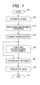
- FIG. 1 is a diagram illustrating signal processing in Example 1 of the present invention.
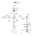
- FIG. 2 is a diagram illustrating a Michelson-type OCT apparatus in Example 1 of the present invention.
- FIGS. 3A, 3B and 3C are diagrams illustrating a time chart in Example 1 of the present invention.
- FIG. 4 is a diagram illustrating a Mach-Zehnder-type OCT apparatus in Example 2 of the present invention.
- FIG. 5 is a diagram illustrating signal processing in Example 2 of the present invention.
- An embodiment of the present invention provides an optical tomographic image generating method for generating a tomographic image of an object, the method including: obtaining signals for a plurality of frames obtained by applying a light beam to the object; obtaining respective complex number data by performing Fourier transformation of the signals for the plurality of frames; synthesizing the plurality of frames in complex number form using the respective complex number data; generating a tomographic image based on the synthesized data.
- the displacement of the frames may be computed before synthesizing the signals, to synthesize the plurality of frames based on such information.
- Example 1 of the present invention will be described.
- an imaging apparatus that can be used for the present invention is not limited to this apparatus, and any type of interferometer, such as a Mach-Zehnder interferometer, for example, can be employed.
- a displacement computation is performed based on real number data, which is different from Example 2 described later.
- FIG. 2 is a schematic diagram illustrating an imaging apparatus using a Michelson-type optical system (Michelson interferometer) according to the present example.
- the measuring beam 214 enters an eye 217, which is an object, via an XY scanner 208 and objective lenses 205-1 and 205-2. Then, the measuring beam 214 that has entered the eye passes through a cornea 216 and then reaches a retina 218.
- the return beam 215 reflected and scattered by the retina 218 of the eye 217 returns to the objective lens 205-2 and 205-1, the XY scanner 208 and the beam splitter 204 in this order. Furthermore, the return beam 215 is guided to a spectroscope 211 via a lens 203-2.
- the spectroscope 211 includes, e.g., a lens, a grating and an image sensor. For the image sensor, a CCD or CMOS line sensor may be used. Signals obtained by the line sensor in the spectroscope 211 are sent to a computer 212 and stored in a memory, and the later-described processing is performed on the signals.
- the reference beam 213 is reflected by a reference mirror 209 via a dispersion compensation glass 207, and passes through the dispersion compensation glass 207 again and returns to the beam splitter 204.
- the dispersion compensation glass 207 is provided for compensating for dispersion caused by the eye 217 and the objective lenses 205-1 and 205-2.
- the reference mirror 209 can adjust the length of the optical path of the reference beam by means of a mirror adjustment mechanism 210.
- the reference beam 213 and the return beam 215 are combined by the beam splitter 204. Then, this combined beam is guided to the spectroscope 211 and detected by the spectroscope 211.
- a portion with its length coincident with that of the reference beam is referred to as a coherence gate.
- the position of the reference mirror 209 is adjusted so that the coherence gate is close to the retina 218.
- a superluminescent diode which is a typical low-coherence light source
- a light beam from the light source 201 has, for example, a central wavelength of 840 nm and a bandwidth of 50 nm. It should be noted that a band width is an important parameter because it affects the resolution in the optical axis direction of an obtained tomographic image.
- the type of the light source 201 is an SLD, here, any light source that can emit low-coherence light may be employed, and, e.g., amplified spontaneous emission (ASE) may be used. It should be understood that depending on the nature of the object, another light source such as a halogen lump may be used.
- the wavelength affects the resolution in the traverse direction of an obtained tomographic image, the wavelength is desirably short where emphasizing the resolution in the traverse direction.
- the computer 212 controls the spectroscope 211, the XY scanner 208, the mirror adjustment mechanism 210, and a focusing mechanism 206, in addition to computing and controlling described later. It should be understood that the computer 212 can also perform, e.g., data input, image processing, image display and data storage.
- Measurement is started in step A1.
- the OCT apparatus is activated and an eye of interest is set in place. Furthermore, necessary adjustments have been made by an operator and measurement has been started.
- step A2 signals are obtained.
- a three-dimensional image is obtained by two-dimensionally scanning the retina 218 by means of the XY scanner 208 while applying the measuring beam 214 to the retina 218 of a fundus.
- an X direction perpendicular to the optical axis of an eye is a fast scan direction
- a Y direction is a slow scan direction.
- FIGS. 3A, 3B and 3C are timing charts illustrating X position, Y position and recording timing, respectively.
- FIGS. 3A, 3B and 3C illustrate obtainment of three frames to be synthesized, a first frame 301, a second frame 302 and a third frame 303, from among the 500 frames.
- the time between the frame recordings is used for, e.g., displacement of the scanner in the X and Y directions for recording in the next position, and data transfer to the computer 212.
- the scan pattern is not limited thereto, and images of a plurality of frames having the same Y position may be taken to subsequently synthesize the images. Also, data may be obtained not only by movement of the scanner in a linear direction such as the X direction or the Y direction, but also by rotating the scanner like circle scanning.
- the positional difference in the Y direction is desirably no more than several times the traverse resolution of the OCT apparatus (which is generally determined by the beam diameter of the measuring beam on the object to be measured). In the case of the present example, where the beam diameter of the measuring beam on the object to be measured is around 5 micrometers, the positional difference is around a few tens of micrometers in the Y direction.
- wavelength-wavenumber conversion is performed.
- data from the spectroscope 211 includes wavelengths and the intensities in the wavelengths.
- the wavelengths are usually sampled at regular intervals.
- a function of the intensity data relative to the wavelengths is created.
- the respective wavelengths are converted into wavenumbers to create a function of the intensity data relative to the wavenumbers. Since a wavenumber is the reciprocal of a wavelength, the wavenumbers do not have regular intervals if they are used as they are. So, wavenumbers are newly allocated so that the 1024 wavenumbers have regular intervals.
- intensity data corresponding to these wavenumbers is computed.
- the computation method may be, for example, interpolation such as general linear interpolation or spline interpolation.
- the computation is desirably a linear operation. Consequently, a two-dimensional array of 1024 x 512 elements, which include wavenumbers with regular intervals and the intensities for the wavenumbers, is obtained for each frame. It should be understood that where the spectroscope 211 can perform sampling of the wavenumbers at regular intervals, or where an error due to the wavelength-wavenumber conversion causes no problem, step A3 can be skipped.
- step A4 a Fourier transformation is performed.
- the discrete Fourier transformation of intensity data having regular intervals relative to the wavenumbers is performed for the respective columns. Consequently, a two-dimensional array of 1024 x 512 complex numbers is obtained for each frame.
- the m-th row and the (1024-m)-th row in each column have the same intensity. Accordingly, the 0th to 511th rows are extracted to obtain a two-dimensional array of 512 x 512 complex numbers, and such data are sent to the following step.
- step A5 the displacement between frames of which signals are to be synthesized is computed.
- computation of the displacement of the image of the second frame 302 and the image of the third frame 303 relative to the image of the first frame 301 will be described.
- 512 x 512 complex number data for each frame is converted into real numbers.
- an i column (512 elements) in the image of the second frame 302 is selected relative to the 128th column (384 elements in 65th to 448th rows) of the first frame 301, and the difference between the 384 elements of the first frame 301 and the consecutive 384 elements from a j row in the i column is computed to obtain a one-dimensional array.
- the mean square of the elements in the one-dimensional array and the elements selected in the first frame is obtained. This calculation is performed for necessary i columns and j rows, and from among the i columns and j rows, i 1 and j 1 having the smallest mean square are determined.
- the displacement of the image of the third frame 303 is obtained relative to the image of the first frame 301 in a similar manner. Then, the information on the computed displacements is sent to step M.
- the above method may be repeated to enhance the accuracy of the information on the displacements, or the displacements of subpixels may be computed by performing interpolation for each column. It should be understood that another method may be employed for the displacement computation.
- step M the signals are synthesized.
- the two-dimensional complex number data obtained in step A4 are averaged based on the information on the displacements obtained in step A5.
- the complex number data for the second frame 302, which is a result of parallel or rotational displacement, is added to the complex number data for the first frame 301. It should be understood that since the array is a discrete one, necessary interpolation processing has been applied to the image of the second frame 302.
- the complex number data for the third frame 303 which is also a result of parallel or rotational displacement, is further added to the complex number data 301 with the complex number data for the second frame 302 added thereto. Then, the synthesized complex number data is converted into real numbers and sent to step A6.
- weighted averaging may be employed for the averaging, the effect of noise-reduction may vary if different weights are provided to the complex numbers. It should be noted that frame data determined to have a measurement error may be taken out.
- step A6 the data is shown in a display screen of the computer 212 as one tomographic image.
- step A7 the processing ends in step A7.
- an image with its noise reduced may be obtained by applying the above-described processing to data for a plurality of frames obtained via a network.
- step M in the present example frame images are added up in complex number form and subsequently the complex numbers are converted into real numbers, while in conventional techniques, after conversion into real numbers, frame images are added up to synthesize the signals.
- the difference in principle between these methods boils down to the difference between the case where two complex numbers are added up after they are converted into real numbers, and the case where two complex numbers are added up before conversion into real numbers, and subsequently converted into real numbers.
- Expressions 2 and 3 have the relationship expressed by Expression 4 when Expressions 2 and 3 are raised to the second power and the common term is deducted from Expressions 2 and 3. (The relationship can easily be proven when both sides are further raised to the second power.)
- the value of Expression 2 is no more than the value of Expression 3. This is important in noise-reduction. That is, in the case of random noise, the noise includes positive components and negative components. If the elements are added up in complex number form, the positive components and the negative components of the noise cancel each other out, and thus, more efficient averaging can be performed. Using linear transformation in the respective steps of the signal processing, the same result can be obtained even if data before conversion into complex numbers are superimposed on another data.
- Table 1 indicates comparison of signal/noise ratios (SNR). This result is somewhat different from the result obtained by the process in the present example because as in Example 2, which will be described later, the lines in frames are synthesized. However, the table provides data sufficient for comparison of SNRs in terms of the timing of conversion of pixel values into real numbers. For the recording object, the range of around 6 mm of the retina of a normal eye with the macula as its center was measured. The number of lines is 2048.
- the 2048 lines were reduced to 512 lines by extracting a line every four lines from the 2048 lines to generate a tomographic image for one frame, which has not been objected to synthesizing
- the 2048 lines were reduced to 1024 lines by extracting a line every two lines, and adjacent two lines are synthesized to generate a tomographic image for one frame, which has 512 lines
- consecutive four lines in the 2048 lines were synthesized to generate a tomographic image for one frame, which has 512 lines.
- the table indicates comparison between the SNR where synthesizing was performed before conversion from complex numbers to real numbers, and the SNR after conversion into real numbers.
- a SNR is the ratio of the smallest value among the root mean square (RMS) of noise in each line to the largest value among the pixels.
- Table 1 Comparison of SNRs [dB] Synthesizing before conversion into real numbers Synthesizing after conversion into real numbers 512 (No averaging performed) 40.22 40.22 1024 (Two lines averaged) 42.84 40.27 2048 (Four lines averaged) 45.74 40.35
- Example 2 of the present invention will be described. Here, the description will be given especially for differences from Example 1.
- a tomographic image is generated by means of an imaging apparatus using a Mach-Zehnder interferometer.
- an imaging apparatus that can be used in the present invention is not limited to this interferometer, and for example, any interferometer, such as a Michelson interferometer, can be employed.
- signal processing in the present example includes synthesizing signals of a frame in the frame, and computing a displacement including phase components. Although a mode including both of these features will be described below, the present invention is not limited to the below description, and the present invention may be applied to a mode including only one of the features.
- FIG. 4 is a schematic diagram illustrating an imaging apparatus using a Mach-Zehnder-type optical system in the present example. The same components as those in FIG. 2 are provided with the same symbols, and a part of the description will be omitted.
- a light beam emitted from a light source 201 is transmitted via a fiber 202 and divided into a measuring beam 214 and a reference beam 213 by a fiber coupler 401-1.
- the measuring beam 214 enters a port 1 of a circulator 402-2 and exits from a port 2 of the circulator 402-2, and reaches a lens 403-2. Furthermore, the measuring beam 214 reaches a retina 218 via an XY scanner 208, objective lenses 205-1 and 205-2, and a cornea 216. A return beam 215 scattered and reflected by the retina 218 returns to the objective lenses 205-2 and 205-1 and the XY scanner 208, enters the port 2 of the circulator 402-2 and exits from a port 3 of the circulator 402-2, and reaches a fiber coupler 401-2.
- the reference beam 213 enters a port 1 of a circulator 402-1 and exits from a port 2 of the circulator 402-1, and is transmitted via a lens 403-1 and a dispersion compensation glass 207 and reflected by a reference mirror 209.
- the reflected reference beam 213 returns to the lens 403-1 and the port 2 of the circulator 402-1 via the dispersion compensation glass 207, and exits from the port 3 of the circulator 402-1, and reaches the fiber coupler 401-2.
- the reference mirror 209 can adjust the optical path length by means of a mirror adjustment mechanism 210.
- the reference beam 213 and the return beam 215 are combined by the fiber coupler 401-2, and the combined beam is guided to a spectroscope 211 and detected, and sent to a computer 212.
- Example 2 signal processing in Example 2, which is performed by the OCT apparatus illustrated in FIG. 4 , will be described.
- the same symbols as those in FIG. 1 represent similar processing.
- step A2 An image with 2048 lines is obtained for one frame, and 500 such frames are obtained. Consequently, data of 1024 x 2048 elements is obtained per frame.
- one of the features of the present example is that signals are synthesized in the respective frames.
- the effect of noise-reduction is the same in principle if an object does not move.
- the problem is not simple where the object is a moving one like an eye.
- the line rate is 20 kHz
- the time required for obtaining data for one frame is 26 msec for 512 lines, and 102 msec for 2048 lines.
- the frame intervals are around 30 msec and 106 msec, respectively.
- the difference in position between the obtained lines is desirably not more than several times the beam diameter.
- step S adjacent lines in each frame are synthesized. Every four adjacent lines in 2048 lines are synthesized to obtain data having 1024 x 512 elements for each frame.
- step A3 wavelength-to-wavenumber conversion is performed.
- step A4 Fourier transform is performed. Then, necessary parts are clipped to obtain a two-dimensional-array data of 512 x 512 complex numbers for each frame, and the data is sent to the next step.
- step A5-1 the displacement is computed.
- the displacement computation has been performed after conversion into real numbers
- the displacement computation is performed in complex number form.
- the difference between the data is computed in complex number form, and the displacement for the case where the mean square of the computation result is the smallest is extracted. Consequently, the displacement including phases can be computed.
- the computation may be performed after converting the complex number data into polar coordinates.
- step M averaging of the two-dimensional array data of complex numbers obtained in step A4 is performed based on the information relating to the displacement including phases obtained in step A5-1. Then, the result is converted into real numbers and such data is sent to step A6.
- step A6 one tomographic image is obtained.
- step A7 the processing ends.
- the displacement including phases can be computed, enabling further image quality enhancement to be expected.
- the present invention can be practiced by performing the following processing.
- software (computer program) providing the functions provided by the above-described embodiments is supplied to a system or an apparatus via a network or a recording medium of various types, and a computer (or a CPU or MPU or the like) in the system or the apparatus reads and executes the program.
- the computer program includes obtaining signals for a plurality of frames by applying a light beam to an object; obtaining respective complex number data by performing Fourier transformation of the signals for the plurality of frames; synthesizing the plurality of frames in complex number form using the respective complex number data; and generating a tomographic image based on the synthesized data.
- the computer program may further include obtaining frame displacement information, and synthesizing signals for a frame within the frame.
- aspects of the present invention can also be realized by a computer of a system or apparatus (or devices such as a CPU or MPU) that reads out and executes a program recorded on a memory device to perform the functions of the above-described embodiment(s), and by a method, the steps of which are performed by a computer of a system or apparatus by, for example, reading out and executing a program recorded on a memory device to perform the functions of the above-described embodiment(s).
- the program is provided to the computer for example via a network or from a recording medium of various types serving as the memory device (e.g., computer-readable medium).
- the system or apparatus, the program, and the recording medium where the program is stored are included as being within the scope of the present invention.
Landscapes
- Health & Medical Sciences (AREA)
- Life Sciences & Earth Sciences (AREA)
- Physics & Mathematics (AREA)
- Engineering & Computer Science (AREA)
- General Health & Medical Sciences (AREA)
- Biomedical Technology (AREA)
- Biophysics (AREA)
- Radiology & Medical Imaging (AREA)
- Veterinary Medicine (AREA)
- Heart & Thoracic Surgery (AREA)
- Medical Informatics (AREA)
- Molecular Biology (AREA)
- Surgery (AREA)
- Animal Behavior & Ethology (AREA)
- Nuclear Medicine, Radiotherapy & Molecular Imaging (AREA)
- Public Health (AREA)
- General Physics & Mathematics (AREA)
- Pathology (AREA)
- Signal Processing (AREA)
- Ophthalmology & Optometry (AREA)
- Mathematical Physics (AREA)
- Artificial Intelligence (AREA)
- Computer Vision & Pattern Recognition (AREA)
- Physiology (AREA)
- Psychiatry (AREA)
- Investigating Or Analysing Materials By Optical Means (AREA)
- Eye Examination Apparatus (AREA)
Applications Claiming Priority (1)
| Application Number | Priority Date | Filing Date | Title |
|---|---|---|---|
| JP2009244678A JP4902721B2 (ja) | 2009-10-23 | 2009-10-23 | 光断層画像生成装置及び光断層画像生成方法 |
Publications (1)
| Publication Number | Publication Date |
|---|---|
| EP2314985A1 true EP2314985A1 (en) | 2011-04-27 |
Family
ID=43498496
Family Applications (1)
| Application Number | Title | Priority Date | Filing Date |
|---|---|---|---|
| EP10188406A Withdrawn EP2314985A1 (en) | 2009-10-23 | 2010-10-21 | Optical tomographic image generating apparatus and optical tomographic image generating method |
Country Status (4)
| Country | Link |
|---|---|
| US (2) | US8504141B2 (enExample) |
| EP (1) | EP2314985A1 (enExample) |
| JP (1) | JP4902721B2 (enExample) |
| CN (1) | CN102038486B (enExample) |
Families Citing this family (24)
| Publication number | Priority date | Publication date | Assignee | Title |
|---|---|---|---|---|
| JP5306075B2 (ja) * | 2008-07-07 | 2013-10-02 | キヤノン株式会社 | 光干渉断層法を用いる撮像装置及び撮像方法 |
| JP5627260B2 (ja) | 2009-05-22 | 2014-11-19 | キヤノン株式会社 | 撮像装置および撮像方法 |
| JP4902721B2 (ja) * | 2009-10-23 | 2012-03-21 | キヤノン株式会社 | 光断層画像生成装置及び光断層画像生成方法 |
| JP5036785B2 (ja) * | 2009-10-23 | 2012-09-26 | キヤノン株式会社 | 光断層画像生成方法及び光断層画像生成装置 |
| JP5808119B2 (ja) | 2010-04-13 | 2015-11-10 | キヤノン株式会社 | 模型眼、光断層画像撮像装置の調整方法、及び評価方法 |
| JP2011257160A (ja) | 2010-06-04 | 2011-12-22 | Canon Inc | 光干渉断層撮像装置、光干渉断層撮像方法、およびプログラム |
| JP2012042348A (ja) | 2010-08-19 | 2012-03-01 | Canon Inc | 断層画像表示装置およびその制御方法 |
| JP5733960B2 (ja) | 2010-11-26 | 2015-06-10 | キヤノン株式会社 | 撮像方法および撮像装置 |
| US8517537B2 (en) | 2011-01-20 | 2013-08-27 | Canon Kabushiki Kaisha | Optical coherence tomographic imaging method and optical coherence tomographic imaging apparatus |
| US9161690B2 (en) | 2011-03-10 | 2015-10-20 | Canon Kabushiki Kaisha | Ophthalmologic apparatus and control method of the same |
| JP5901124B2 (ja) | 2011-03-10 | 2016-04-06 | キヤノン株式会社 | 撮像装置およびその制御方法 |
| JP5955163B2 (ja) | 2011-09-06 | 2016-07-20 | キヤノン株式会社 | 画像処理装置および画像処理方法 |
| KR101862354B1 (ko) | 2012-01-09 | 2018-05-30 | 삼성전자주식회사 | 단층 영상 생성 방법 및 그 방법을 수행하는 단층 영상 생성 장치 |
| JP6101048B2 (ja) | 2012-02-20 | 2017-03-22 | キヤノン株式会社 | 画像処理装置及び画像処理方法 |
| JP6184114B2 (ja) * | 2013-01-31 | 2017-08-23 | キヤノン株式会社 | 光干渉断層撮像装置およびその制御方法 |
| JP5689499B2 (ja) * | 2013-05-17 | 2015-03-25 | ファナック株式会社 | 防錆機能を有するワイヤ放電加工機 |
| US9267783B1 (en) | 2014-09-10 | 2016-02-23 | Carl Zeiss Meditec, Inc. | Split integration mode acquisition for optimized OCT imaging at multiple speeds |
| EP3588061B1 (en) | 2014-12-23 | 2023-04-19 | Apple Inc. | Optical inspection system and method including accounting for variations of optical path length within a sample |
| KR102615932B1 (ko) | 2015-09-01 | 2023-12-21 | 애플 인크. | 물질의 비접촉 감지를 위한 레퍼런스 스위치 아키텍처 |
| JP2017099759A (ja) * | 2015-12-03 | 2017-06-08 | キヤノン株式会社 | 光音響測定装置の評価用ファントムおよびパッケージファントム |
| EP4589271A3 (en) | 2016-04-21 | 2025-07-30 | Apple Inc. | Optical system for reference switching |
| EP3688446A2 (en) | 2017-09-29 | 2020-08-05 | Apple Inc. | Resolve path optical sampling architectures |
| CN114545550B (zh) | 2018-02-13 | 2024-05-28 | 苹果公司 | 具有集成边缘外耦合器的集成光子装置 |
| US11852318B2 (en) | 2020-09-09 | 2023-12-26 | Apple Inc. | Optical system for noise mitigation |
Citations (4)
| Publication number | Priority date | Publication date | Assignee | Title |
|---|---|---|---|---|
| WO2003011764A2 (en) * | 2001-08-03 | 2003-02-13 | Volker Westphal | Real-time imaging system and method |
| US20080175465A1 (en) * | 2007-01-19 | 2008-07-24 | Thorlabs, Inc. | Optical Coherence Tomography Imaging System and Method |
| US20080234972A1 (en) * | 2007-03-23 | 2008-09-25 | Kabushi Kaisha Topcon | Optical image measurement device and image processing device |
| US20080273783A1 (en) * | 2007-05-04 | 2008-11-06 | Bioptigen, Inc. | Methods, Systems and Computer Program Products For Mixed-Density Optical Coherence Tomography (OCT) Imaging |
Family Cites Families (13)
| Publication number | Priority date | Publication date | Assignee | Title |
|---|---|---|---|---|
| JP2989364B2 (ja) * | 1992-03-12 | 1999-12-13 | シャープ株式会社 | 画像処理装置及び画像処理方法 |
| US7222961B2 (en) * | 2002-08-05 | 2007-05-29 | Kestrel Corporation | Method for detecting a functional signal in retinal images |
| JP4850495B2 (ja) * | 2005-10-12 | 2012-01-11 | 株式会社トプコン | 眼底観察装置及び眼底観察プログラム |
| US8711144B2 (en) * | 2006-08-01 | 2014-04-29 | Siemens Medical Solutions Usa, Inc. | Perception-based artifact quantification for volume rendering |
| JP4461259B2 (ja) * | 2006-08-09 | 2010-05-12 | 国立大学法人 筑波大学 | 光断層画像の処理方法 |
| JP2008142443A (ja) * | 2006-12-13 | 2008-06-26 | Fujifilm Corp | 光断層画像化装置 |
| US8000774B2 (en) * | 2007-01-03 | 2011-08-16 | Infraredx, Inc. | Method and system for intra luminal thrombus detection |
| JP5448353B2 (ja) | 2007-05-02 | 2014-03-19 | キヤノン株式会社 | 光干渉断層計を用いた画像形成方法、及び光干渉断層装置 |
| JP5199031B2 (ja) * | 2008-11-05 | 2013-05-15 | 株式会社ニデック | 眼科撮影装置 |
| JP5339934B2 (ja) | 2009-01-22 | 2013-11-13 | キヤノン株式会社 | 光断層撮像装置および光断層撮像方法 |
| JP5605999B2 (ja) | 2009-03-06 | 2014-10-15 | キヤノン株式会社 | 光干渉断層撮像方法および装置 |
| JP5605998B2 (ja) | 2009-03-06 | 2014-10-15 | キヤノン株式会社 | 光干渉断層撮像方法および装置 |
| JP4902721B2 (ja) * | 2009-10-23 | 2012-03-21 | キヤノン株式会社 | 光断層画像生成装置及び光断層画像生成方法 |
-
2009
- 2009-10-23 JP JP2009244678A patent/JP4902721B2/ja not_active Expired - Fee Related
-
2010
- 2010-09-29 US US12/893,439 patent/US8504141B2/en not_active Expired - Fee Related
- 2010-10-21 EP EP10188406A patent/EP2314985A1/en not_active Withdrawn
- 2010-10-22 CN CN201010515565.5A patent/CN102038486B/zh not_active Expired - Fee Related
-
2013
- 2013-06-18 US US13/920,180 patent/US20130278897A1/en not_active Abandoned
Patent Citations (5)
| Publication number | Priority date | Publication date | Assignee | Title |
|---|---|---|---|---|
| WO2003011764A2 (en) * | 2001-08-03 | 2003-02-13 | Volker Westphal | Real-time imaging system and method |
| US20080175465A1 (en) * | 2007-01-19 | 2008-07-24 | Thorlabs, Inc. | Optical Coherence Tomography Imaging System and Method |
| US20080234972A1 (en) * | 2007-03-23 | 2008-09-25 | Kabushi Kaisha Topcon | Optical image measurement device and image processing device |
| JP2008237238A (ja) | 2007-03-23 | 2008-10-09 | Topcon Corp | 光画像計測装置、画像処理装置及びプログラム |
| US20080273783A1 (en) * | 2007-05-04 | 2008-11-06 | Bioptigen, Inc. | Methods, Systems and Computer Program Products For Mixed-Density Optical Coherence Tomography (OCT) Imaging |
Also Published As
| Publication number | Publication date |
|---|---|
| CN102038486B (zh) | 2013-05-08 |
| CN102038486A (zh) | 2011-05-04 |
| US20130278897A1 (en) | 2013-10-24 |
| JP4902721B2 (ja) | 2012-03-21 |
| US20110098560A1 (en) | 2011-04-28 |
| US8504141B2 (en) | 2013-08-06 |
| JP2011087813A (ja) | 2011-05-06 |
Similar Documents
| Publication | Publication Date | Title |
|---|---|---|
| EP2314985A1 (en) | Optical tomographic image generating apparatus and optical tomographic image generating method | |
| JP5036785B2 (ja) | 光断層画像生成方法及び光断層画像生成装置 | |
| US20130003077A1 (en) | Tomographic imaging apparatus and control apparatus for tomographic imaging apparatus | |
| US8836952B2 (en) | Optical coherence tomographic imaging method and optical coherence tomographic imaging apparatus | |
| JP5605999B2 (ja) | 光干渉断層撮像方法および装置 | |
| US9058652B2 (en) | Method for reducing noise in tomographic image and recording medium having noise reducing program stored therein | |
| US20120075640A1 (en) | Tomography apparatus and tomogram correction processing method | |
| US10420462B2 (en) | Image processing apparatus that generates a tomographic image of a subject based on phase-adjusted measurement signals from which a background signal is subtracted, and related imaging apparatus, image processing method, and computer readable storage medium | |
| JP2011257160A (ja) | 光干渉断層撮像装置、光干渉断層撮像方法、およびプログラム | |
| US20190290117A1 (en) | Interferometric fundus imaging method | |
| JP5506504B2 (ja) | 撮像装置及び撮像方法 | |
| JP5637721B2 (ja) | 断層撮像装置および断層撮像装置の制御装置 | |
| JP2007127425A (ja) | 光断層画像化法における補正方法 | |
| JP5530241B2 (ja) | 信号処理方法、信号処理デバイス及び光画像計測装置 | |
| JP2022524547A (ja) | 高速歯科用光コヒーレンストモグラフィシステム | |
| JP5451822B2 (ja) | 光断層画像生成方法及び光断層画像生成装置 | |
| JP6047202B2 (ja) | 光干渉断層撮像装置、光干渉断層撮像方法、およびプログラム | |
| JP5746741B2 (ja) | 画像生成装置、画像生成システム及び画像生成方法 | |
| JP5395888B2 (ja) | 画像生成装置、画像生成システム及び画像生成方法 | |
| JP5637720B2 (ja) | 断層撮像方法および断層撮像装置の制御装置 | |
| JP2018073138A (ja) | 画像生成方法、画像生成システムおよびプログラム |
Legal Events
| Date | Code | Title | Description |
|---|---|---|---|
| PUAI | Public reference made under article 153(3) epc to a published international application that has entered the european phase |
Free format text: ORIGINAL CODE: 0009012 |
|
| AK | Designated contracting states |
Kind code of ref document: A1 Designated state(s): AL AT BE BG CH CY CZ DE DK EE ES FI FR GB GR HR HU IE IS IT LI LT LU LV MC MK MT NL NO PL PT RO RS SE SI SK SM TR |
|
| AX | Request for extension of the european patent |
Extension state: BA ME |
|
| 17P | Request for examination filed |
Effective date: 20111027 |
|
| STAA | Information on the status of an ep patent application or granted ep patent |
Free format text: STATUS: THE APPLICATION HAS BEEN WITHDRAWN |
|
| 18W | Application withdrawn |
Effective date: 20160802 |