EP2314412B2 - Laser machining apparatus and method for forming a surface on an unfinished product - Google Patents
Laser machining apparatus and method for forming a surface on an unfinished product Download PDFInfo
- Publication number
- EP2314412B2 EP2314412B2 EP10188598.6A EP10188598A EP2314412B2 EP 2314412 B2 EP2314412 B2 EP 2314412B2 EP 10188598 A EP10188598 A EP 10188598A EP 2314412 B2 EP2314412 B2 EP 2314412B2
- Authority
- EP
- European Patent Office
- Prior art keywords
- blank
- pulse
- laser
- laser beam
- produced
- Prior art date
- Legal status (The legal status is an assumption and is not a legal conclusion. Google has not performed a legal analysis and makes no representation as to the accuracy of the status listed.)
- Active
Links
- 238000000034 method Methods 0.000 title claims description 40
- 238000003754 machining Methods 0.000 title claims description 16
- 239000000463 material Substances 0.000 claims description 60
- 238000005520 cutting process Methods 0.000 claims description 50
- 238000004519 manufacturing process Methods 0.000 claims description 8
- 239000000126 substance Substances 0.000 claims 4
- 229910003460 diamond Inorganic materials 0.000 description 6
- 239000010432 diamond Substances 0.000 description 6
- 238000001208 nuclear magnetic resonance pulse sequence Methods 0.000 description 5
- 238000002679 ablation Methods 0.000 description 4
- 238000010586 diagram Methods 0.000 description 3
- 238000006073 displacement reaction Methods 0.000 description 3
- 238000000227 grinding Methods 0.000 description 2
- 238000000608 laser ablation Methods 0.000 description 2
- 238000012986 modification Methods 0.000 description 2
- 230000004048 modification Effects 0.000 description 2
- 238000005229 chemical vapour deposition Methods 0.000 description 1
- 239000000109 continuous material Substances 0.000 description 1
- 230000006735 deficit Effects 0.000 description 1
- 230000001419 dependent effect Effects 0.000 description 1
- 238000000605 extraction Methods 0.000 description 1
- 239000002184 metal Substances 0.000 description 1
- 230000003287 optical effect Effects 0.000 description 1
- 238000003672 processing method Methods 0.000 description 1
- 230000005855 radiation Effects 0.000 description 1
- 238000000859 sublimation Methods 0.000 description 1
- 230000008022 sublimation Effects 0.000 description 1
- 239000013589 supplement Substances 0.000 description 1
- 239000002699 waste material Substances 0.000 description 1
Images


Classifications
-
- B—PERFORMING OPERATIONS; TRANSPORTING
- B23—MACHINE TOOLS; METAL-WORKING NOT OTHERWISE PROVIDED FOR
- B23K—SOLDERING OR UNSOLDERING; WELDING; CLADDING OR PLATING BY SOLDERING OR WELDING; CUTTING BY APPLYING HEAT LOCALLY, e.g. FLAME CUTTING; WORKING BY LASER BEAM
- B23K26/00—Working by laser beam, e.g. welding, cutting or boring
- B23K26/36—Removing material
-
- B—PERFORMING OPERATIONS; TRANSPORTING
- B23—MACHINE TOOLS; METAL-WORKING NOT OTHERWISE PROVIDED FOR
- B23K—SOLDERING OR UNSOLDERING; WELDING; CLADDING OR PLATING BY SOLDERING OR WELDING; CUTTING BY APPLYING HEAT LOCALLY, e.g. FLAME CUTTING; WORKING BY LASER BEAM
- B23K26/00—Working by laser beam, e.g. welding, cutting or boring
- B23K26/08—Devices involving relative movement between laser beam and workpiece
- B23K26/0823—Devices involving rotation of the workpiece
-
- B—PERFORMING OPERATIONS; TRANSPORTING
- B23—MACHINE TOOLS; METAL-WORKING NOT OTHERWISE PROVIDED FOR
- B23K—SOLDERING OR UNSOLDERING; WELDING; CLADDING OR PLATING BY SOLDERING OR WELDING; CUTTING BY APPLYING HEAT LOCALLY, e.g. FLAME CUTTING; WORKING BY LASER BEAM
- B23K26/00—Working by laser beam, e.g. welding, cutting or boring
- B23K26/08—Devices involving relative movement between laser beam and workpiece
- B23K26/083—Devices involving movement of the workpiece in at least one axial direction
-
- B—PERFORMING OPERATIONS; TRANSPORTING
- B23—MACHINE TOOLS; METAL-WORKING NOT OTHERWISE PROVIDED FOR
- B23K—SOLDERING OR UNSOLDERING; WELDING; CLADDING OR PLATING BY SOLDERING OR WELDING; CUTTING BY APPLYING HEAT LOCALLY, e.g. FLAME CUTTING; WORKING BY LASER BEAM
- B23K26/00—Working by laser beam, e.g. welding, cutting or boring
- B23K26/08—Devices involving relative movement between laser beam and workpiece
- B23K26/0869—Devices involving movement of the laser head in at least one axial direction
- B23K26/0876—Devices involving movement of the laser head in at least one axial direction in at least two axial directions
Definitions
- the invention relates to a laser machining device and a method for producing a surface on a blank.
- one or more cutting edges, rake faces and flanks should be formed on the blank.
- the surface to be produced can be, for example, a cutting surface or a free surface.
- the edge, in particular the cutting edge can be formed at the same time. In this way, a cutting tool can be produced from the blank.
- the blank can also be made up of several layers of material or of several elements joined together.
- laser processing machines are also known in which the laser is moved relative to the blank via machine axes. It is true that a higher level of accuracy and a higher quality of the surfaces and edges produced on the blank can be achieved in this way, but the removal rates that can be achieved are low. This is due to the fact that the dynamics and the speed of the machine axes are limited. Great effort is required to increase the dynamics of the machine axes, which makes the laser processing machine very expensive.
- a method and a device for laser machining a blank are, for example, from DE 299 08 585 U1 known.
- the device has a laser for generating laser beam pulses.
- the laser and/or the workpiece holder is/are moved in the direction and transversely to the optical axis of the laser via a drive unit.
- the laser beam is moved in several parallel or overlapping lines over the entire width of the surface to be removed.
- the material is therefore removed in punctiform form at the impact points of the laser beam pulse.
- the impact points overlap by between 5 and 25 percent.
- the removal rate is low with this procedure and the processing times are correspondingly long.
- WO 2006/038017 A2 two different embodiments of a laser processing device are described.
- a pulse area is formed from a plurality of impingement points of the laser beam pulses arranged next to one another with the aid of a laser scanner.
- the material is removed at the points of impact of the laser beam pulses in the pulse area.
- the blank is drilled through. After piercing, a feed motion begins to cut through the blank in one go. This corresponds to the two variants of laser processing already described at the outset.
- a method is known in which the impact points of the laser beam pulses are placed along a grid using a scanner.
- the scanner is designed to allow rapid and accurate offsetting of the laser beam pulses with a predetermined overlap.
- the scanner has two of the scanners two beam guides which, for example, cause deflection movements of the laser beam pulses aligned at right angles to one another. The offset between two consecutive laser beam pulses can be increased as a result.
- DE 10 2007 012 816 A1 describes a method for machining workpieces using a laser beam.
- the laser beam is guided over the workpiece surface within a maximum achievable working window by means of a beam guide.
- the beam guide and the workpiece can be displaced relative to one another in a displacement direction by a displacement distance such that they can assume a first and a second relative working position relative to one another.
- the working windows to be set one after the other by different relative positioning of the workpiece and beam guide overlap. In the overlapping area, locations of the workpiece can be machined either from one working window of the first relative working position or from the other working window of the second relative working position.
- the end WO 2005/044505 A1 known method provides that different laser heads are used on a workpiece depending on the shape to be produced (bore or die).
- the two laser heads are operated with different parameters, such as pulse frequency, pulse duration, pulse peak power, etc. of the laser.
- a pulsed laser that generates laser beam pulses with a predetermined pulse frequency.
- the laser beam pulses are directed in a fixed, predetermined sequence onto a large number of impact points on the surface of the blank. These predetermined impact points form a two-dimensional pulse area on the surface of the blank.
- a sequence of laser beam pulses is thus generated, which are directed to different predetermined impact points in the pulse area. This sequence is repeated over and over again in a predetermined order. Meanwhile, there is continued relative movement between the blank and the pulse area. The relative movement takes place without the pulse area standing still on the surface of the blank.
- a positioning device moves the blank and/or the deflection device, optionally together with the laser, in a direction of relative movement along the edge or surface to be produced.
- the pulse area moves along the surface of the blank at the speed specified by the positioning device for the relative movement. In this way, material is removed in the area of the pulse surface, which is moved relative to the blank like a tool.
- the invention combines the two previously used alternative laser processing methods.
- the fast scanner optics are used to form the pulse area.
- the scanner optics do not position the laser beam impulses along the desired contour of the surface or edge to be produced, but direct the laser beam impulses to the impact points of the pulse area.
- the simultaneous relative movement of the pulse area in relation to the blank via machine axes ensures the desired accuracy in order to obtain surface and edge profiles with small deviations from the specified profile.
- the positioning device sets an angle of inclination greater than zero between the emission direction of the laser beam pulses and a surface to be produced on the blank.
- the laser beam pulses preferably run at right angles to the direction of relative movement.
- the pulse area is aligned transversely to the area to be generated.
- the angle of inclination can be equal to zero and can be increased during manufacture after a predetermined process state has been reached.
- Pulsed lasers with a frequency between 1 and 10 MHz are preferably used.
- the angle of inclination to be set depends on the blank material to be machined.
- the angle of inclination can range between 0 degrees and 45 degrees, preferably between 5 degrees and 25 degrees.
- the angle of inclination can also be changed during the machining of the blank and set to a desired value via the positioning device. In particular, if the blank consists of several layers of different material and the material to be processed changes as a result in the course of processing, the specified angle of inclination can be adjusted between different values to the respective material.
- the pulse area can have an essentially rectangular contour.
- the impact points forming the pulse area are arranged next to one another within a rectangular contour, so that several of the craters formed at the impact points by the laser beam pulses touch the rectangular contour.
- the outer impact points of the pulse area are arranged on a rectangular line.
- other polygonal areas, elliptical or circular areas or areas in the form of ring segments can also be specified.
- the shape of the pulse area can be adapted to the material removal to be achieved and the desired contour profile to be achieved of the workpiece to be produced from the blank.
- the deflection device directs the laser beam pulses onto impact points which are arranged along a predetermined pulse path.
- the pulse path depends on the shape of the pulse area and preferably has a meandering or spiral course.
- the pulse path can have an impact point as the starting point and an impact point as the end point, where the end point is arranged at the edge of the pulse area which is assigned to the contour to be produced.
- the path end section of the pulse path that has the end point is preferably aligned parallel or tangential to the direction of relative movement. During the reset movement from the end point to the starting point, a relatively large adjustment path is covered, which is significantly greater than the other adjustment paths between two consecutive impact points along the pulse path.
- the direction of movement of the return movement is directed away from the edge and/or surface to be produced. As a result, qualitative impairments of the contour to be produced can be avoided.
- the distance between two consecutive points of impact along the pulse path can be specified as desired, in particular by selecting or adjusting the pulse frequency of the laser and the adjustment speed of the deflection device.
- Two consecutive laser beam pulses can be directed to different impact points in the pulse area.
- the energy of the single impulse or of the impulse sequence aimed at an impact point is predetermined and distributed according to the number of impulses used. The greater the number of laser beam pulses contained in a pulse train, the lower the energy contained in a single laser beam pulse.
- the removal of the material part of the blank that covers the area to be produced and is to be removed is carried out layer by layer in a plurality of removal layers running essentially parallel to the pulse area.
- the thickness of the ablation layer - viewed in the direction of emission of the laser beam pulses - depends on the pulse frequency of the laser and the relative speed of the pulse surface compared to the blank. Layer thicknesses of several hundredths of a millimeter can be achieved.
- the removal layers run transversely in front of the surface to be produced.
- a cutting tool with at least one cutting edge can be produced from the blank.
- the blank preferably has a cutting material layer or a cutting material element which is arranged on a carrier layer or a carrier element.
- the part of material to be removed extends over both layers.
- the positioning device can set a first angle of inclination for removing the material of the cutting material layer and a second angle of inclination for removing the material of the carrier layer. In this way, optimal removal rates can be achieved depending on the material to
- the focus position of the laser beam pulses is preferably adjusted or adjusted via focusing optics or the positioning device.
- the intensity of the laser pulses during the removal of the material of the cutting material layer can be different from the intensity during the removal of the material of the carrier layer. As a result, deviations between the desired shape of the cutting edge or the surface to be produced can be reduced.
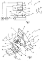
- a laser processing device 20 is shown schematically.
- the laser processing device 20 has a pulsed laser 21 which generates a pulsed laser beam 22 and feeds it to a laser head 19 with a deflection device 23 .
- the deflection device 23 can change the orientation of emitted laser beam pulses 24 and thereby direct the laser beam pulse 24 to a predetermined impingement point 25 on a surface 26 of a blank 27 .
- the deflection device 23 can also be referred to as a scanner device. It also includes focusing optics 28 .
- the blank 27 is held in a receiving area 47 on a workpiece holder 18 .
- the laser processing device 20 has a control device 29 .
- the number of linear axes and rotary axes of the positioning device 30 can vary.
- the positioning device 30 has a first adjustment drive 31, by means of which the laser head 19 can be moved in a first direction 32. This is preferably a linear movement in the first direction 32.
- the first adjustment drive 31 has, for example, a first carriage 33 which is mounted on a first carriage carrier 34 in a linearly displaceable manner. The laser head 19 is fastened on the first carriage 33 .
- the positioning device 30 can have further adjustment drives.
- a second carriage carrier 35 is provided, on which a second carriage 36 is mounted so as to be displaceably guided in a second direction 37 .
- the first carriage carrier 34 is mounted on this second carriage 36 .
- the second direction 37 runs at right angles to the first direction 32.
- the first and second directions 32, 37 span a plane which runs essentially transversely to an emission direction R of the laser beam pulses 24.
- a third direction 38 runs at right angles to the other two directions 32, 37.
- a third carriage 39 is mounted on a third carriage carrier 40 so that it can be displaced linearly in this third direction 38.
- the workpiece carrier 18 can be displaced in the third direction 38 via this carriage arrangement 39, 40, as a result of which the distance between the workpiece holder 18 and thus the blank 27 from the laser head 19 can be adjusted.
- the third direction 38 corresponds to the emission direction R, for example figure 2 the direction of radiation R is aligned essentially horizontally, with a vertical alignment also being possible as an alternative.
- the positioning device 30 can therefore bring about the relative movement between the laser head 19 and the workpiece holder 18 or blank 27 in a relative movement direction V.
- the direction of relative movement V does not have to be spatially constant, but can describe any desired path in relation to the three directions 32, 37, 38.
- the workpiece holder 18 is arranged on the third carriage 39 via a pivoting drive 41, which can execute a pivoting movement of the workpiece holder 18 about a first pivot axis 42a and/or a second pivot axis 42b.
- the first pivot axis 42a runs in the second direction 37, while the second pivot axis 42b extends in the first direction 32.
- an angle at which the laser beam pulse 24 impinges on the blank 27 can be changed and adjusted as desired.
- the positioning device 30 can have additional adjustment drives or swivel or rotary drives for setting the relative position between the blank 27 and the laser beam pulse 24 .
- additional adjustment drives or swivel or rotary drives for setting the relative position between the blank 27 and the laser beam pulse 24 .
- the relative position between the laser head 19 and the workpiece holder 18 to be set by the positioning device 30 is specified by the control device 29 .
- the control device 29 controls the laser head 19 in order to set or change processing parameters before or during the processing of the blank 27 .
- the processing parameters are, for example, the intensity I of the laser beam pulses and/or the pulse frequency f of the laser 21 in a frequency range of preferably 1 MHz to 10 MHz and/or the focal length of the focusing optics 28 and/or the like.
- the laser processing device 20 has a process gas supply 45 and a process gas suction device 46, which are arranged on both sides of the receiving region 47 as viewed in the second direction 37 ( 1 ). In the preferred exemplary embodiment, this creates a process gas flow P in the second direction 37.
- a process gas flow P can be set in the area of the surface 26 to be processed in order to remove the plasma produced during laser ablation by sublimation of the material from the area to be processed to be transported away on blank 27.
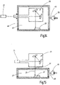
- a vacuum chamber 48 is provided as an alternative to generating the process gas flow P, with the workpiece holder 18 and the receiving area 47 for the blank 27 being located within the vacuum chamber 48 .
- the vacuum chamber 48 is connected to a vacuum pump 50 via a suction line 49 so that a vacuum can be created in the receiving area 47 .
- the deflection device 23 can either be arranged inside the vacuum chamber 48 ( figure 14 ) or alternatively located outside of the vacuum chamber 48, as is the case, for example, in FIGS figures 2 and 15 is shown. In this case the vacuum chamber 48 in the area of the entry point 51 of the laser beam pulse 24 must be transparent for the laser wavelength used.
- the laser beam pulses 24 are aligned with the surface 26 of the blank 27 in the area of a pulse area 55 with the aid of the deflection device 23 .
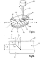
- a laser beam pulse 24 strikes the surface 26 at the point of impact 25 and causes material removal there, as a result of which a funnel-shaped crater 56 is formed, as is shown in figure 6 is illustrated schematically.
- the center point or the central axis of the crater 56 is referred to here as the point of impact 25 .
- a large number of predetermined, spaced impact points 25 form the pulse area 55.
- the control device 29 provides the deflection device 23 with a pulse path B for arranging successive impact points 25 .
- the deflection device 23 directs the laser beam pulses 24 one after the other onto the points of impact 25 of the pulse path B.
- the course of the pulse path B depends on the shape of the pulse area 55 and is evident from the rectangular pulse area 55 figure 3 a meandering course, which is made up of rectilinear partial courses.
- An impact point 25 in one of the corner points of the pulse surface 55 forms a starting point S, which is spaced from the edge 60 or surface 62 to be produced. Starting from the starting point S, the laser beam pulses 24 are placed along the pulse path B up to the point of impact 25 in the diagonally opposite corner of the pulse area, which marks the end point E of the pulse path B.
- the track end section 57 of the pulse track B having the end point E runs, for example, parallel to the surface 62 or edge 60 to be produced. This track end section 57 directly adjoins the surface 62 or edge 60 to be produced.
- a reset movement takes place in the deflection device 23 and the laser beam pulses 24 are then placed on the pulse path B again, beginning at the starting point S.
- the restoring movement is directed away from the contour 60, 62 to be produced. She is in the Figures 3 to 5 each illustrated by a dashed arrow.
- the distance A between two consecutive points of impact 25 along the pulse path B is specified via the pulse frequency f of the laser 21 and the adjustment speed of the deflection device 23 . With changes in direction in the pulse path B, the distance can also vary.
- the path end section 57 having the end point E can also run tangentially to the contour 60, 62 to be produced ( figure 4 ).
- the pulse path B is spiral-shaped.
- the pulse area 55 can also have the shape of a ring segment ( figure 5 ).
- other pulse paths specified in the control device 29 can also be selected, in which all impact points 25 defining the pulse area 55 are passed through in succession from the starting point S to the end point E.
- the starting point S and the end point E are preferably as far apart from one another in the direction of the process gas flow P, with the process gas flowing from the end point E to the starting point S.
- only one laser beam pulse 24 is directed at each impingement point 25, while the next laser beam pulse 24 is directed at another impingement point 25 of the pulse area 55.
- the time interval between two successive laser beam pulses 24 results from the reciprocal of the current pulse frequency f of the laser 21.
- the pulsed laser 21 can be configured as a picosecond laser or femptosecond laser.
- successive laser beam pulses 24 are directed at different impingement points 25, then these laser beam pulses 24 have the intensity I1.
- two or more laser beam pulses 24 can also be directed at an impact point 25 before the next impact point 25 is controlled.
- the deflection device 23 first directs a pulse sequence 65 of a plurality of laser beam pulses 24 onto an impact point 25 before the subsequent pulse sequence 65 is directed onto another impact point 25 .
- the energy contained in a pulse sequence 65 acting on an impact point 25 should correspond to a single laser beam pulse 24 with the intensity I1. Therefore, the intensity I of a single laser beam pulse 24 of a pulse train 65 is reduced.
- the total intensity I of a pulse train 65 is constant. Therefore, the intensity I of a single laser beam pulse 24 in a pulse train 65 corresponds to the quotient of the intensity I1 divided by the number of laser beam pulses 24 contained in the pulse train 65.
- the diameter D of the craters 56 depends on the effective diameter of the laser beam pulses 24 at the point of impact 25, which can be predetermined and preferably adjusted via the focusing optics 28 and, in particular, can also be changed during processing.
- the positioning device 30 simultaneously causes a relative movement of the pulse surface 55 along an edge 60 or surface 62 to be produced on the surface 26 of the blank 27.
- the through the Pulse surface 55 with the large number of impingement points 25 of the laser beam pulses 24 formed material removal area with a predetermined relative speed vrel in the direction of relative movement V, laterally along the edge 60 to be produced or Area 62.
- the relative speed vrel is always not equal to zero as long as at least part of the pulse area 55 strikes the surface 26 of the blank.
- edges or surfaces can be produced from the blank 27 with only a very small deviation from the desired course of the edges or surfaces. This is particularly relevant when manufacturing a cutting tool, on which one or more cutting edges 60 are to be produced, which are delimited by a cutting surface 61 and a flank 62 .
- An angle of inclination ⁇ is set via the positioning device 30 and, for example, the pivoting device 41 .
- the angle of inclination ⁇ is defined between the emission direction R of the laser beam pulses 24 and a plane F in which the surface 62 to be machined from the blank 27 is located in relation to the current position of the pulse surface 55 .
- the plane F represents a tangential plane to the location currently being machined.
- the angle of inclination ⁇ to be set is specified by the control device 29 and can change during the machining of the blank 27 .
- the angle of inclination ⁇ is adapted to the material of the blank 27 to be removed. In the case of blanks 27 that are made up of several different parts or layers of material, an angle of inclination ⁇ that is optimally matched to the material is always ensured in this way, as a result of which the process efficiency is significantly increased.
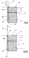
- the blank 27 consists of a cutting material layer, which is formed by a cutting element 70 and consists, for example, of polycrystalline diamond (PCD) or CVD diamond.
- the cutting element 70 is applied to a carrier element 71, which represents a carrier layer and consists of hard metal, for example.
- the two elements 70, 71 are firmly connected to one another via a connecting layer 72, e.g.
- a layer of cutting material could also be applied directly to a carrier layer, for example by a method such as PVD.
- the upper side of the blank 27 forms the rake face 61 of the cutting tool.
- a free face 62 is to be machined out of the blank 27, the desired course of which is illustrated by the line 73.
- the wedge angle to be produced is 90°, for example.
- the first flank section 62a adjoining the cutting edge 60 to be produced encloses the wedge angle with the rake face 61 .
- a material part 63 of the blank In order to produce the free surface 62 and thus also the cutting edge 60, a material part 63 of the blank must be completely removed, which completely covers the free surface 62 to be produced and includes both parts of the cutting element 70 and the carrier element 71.
- the material part 63 contains a side surface of the blank 27 adjoining the cutting face 61. This material part 63 is preferably almost completely sublimated during the removal, so that only a small residual part 64 remains as a piece of waste.
- the remainder comprises less than 10% of the volume of the material portion 63 and preferably less than 5%.
- the laser beam pulses 24 impinging on the surface 26 in the area of the pulse surface 55 lead to a material removal.
- the laser head 19 is moved during the generation of the laser beam pulses 24 in the relative direction of movement V, in the Figures 9 to 13 perpendicular to the image plane, so that the pulse area 55 shifts along the surface 26 of the blank 27.
- the relative speed vrel for this relative movement is a few millimeters per minute and is several orders of magnitude smaller than the adjustment speed of the deflection device 23 for moving the impact points 25 along the pulse path B, which is in the order of meters per second.
- the material is removed in layers along the free surface 62 to be produced.
- a removal layer is removed.
- the contour pass K1 . . . Kn is repeated n times until the material part 63 has been completely removed and the open area 62 has been produced.
- the wear layers have a thickness dS of a few hundredths of a millimeter.
- the depth of material removal increases due to the relative movement in the area of the pulse area 55 counter to the direction of relative movement.
- the material removal depth is greatest at the rear end of the pulse area 55, viewed in the direction of relative movement V, and determines the layer thickness dS of the removal layer, because the front area of the pulse area 55 has already been displaced over this point on the surface 26 of the blank 27 by the continued relative movement.
- the material removal depth in the surface area of the surface 26, which the front end of the pulse area 55 has just reached is still small.
- the angle of inclination ⁇ between the first surface section 62b and the emission direction R is set equal to zero and only increased in terms of amount after the removal of one or more ablation layers following the cutting edge 60 .
- the angle of inclination ⁇ can be positive or negative in the mathematical sense. By determining the appropriate angle of inclination ⁇ , the wedge angle and the cutting edge 60 can be manufactured very precisely. As an alternative to this, an angle of inclination ⁇ not equal to zero can also be set right at the beginning.
- a first angle of inclination ⁇ 1 of approximately 5° to 10° is set.
- the intensity I of the laser beam pulses 24 has a first intensity value IK.
- the intensity of the laser beam pulses 24 can be changed to a second intensity value IG (symbolized by a thick line of the laser beam pulses 24), which is at the example shown here is greater than the first intensity value IK (symbolized by a thin line of the laser beam pulses 24): IK ⁇ IG.
- the intensity I is changed to the second intensity value IG when the material part 63 has been removed in the area of the cutting element 70 and the connecting layer 72 has been reached.
- the control device 29 also causes the angle of inclination ⁇ to change from the first angle of inclination ⁇ 1 to the second angle of inclination ⁇ 2, with the second angle of inclination ⁇ 2 being greater, for example, than the first angle of inclination ⁇ 1.
- the second angle of inclination ⁇ 2 for removing material from the carrier element 71 is approximately 10 to 25° ( figure 12 ).
- the angle of inclination ⁇ is always measured relative to the surface section 62a, 62b to be produced. If the surface 62 to be produced describes an angled or curved course, the positioning device 30 changes the relative position between the laser head 19 and the blank 27 in order to maintain the desired angle of inclination ⁇ .
- the invention relates to a method and a device for laser machining a blank 27.
- a cutting tool with a cutting edge 60 and a flank 62 is to be produced from the blank 27.
- Laser beam pulses 24 are generated by a laser and directed onto a surface 26 of the blank 27 via a deflection device 23 .
- a laser beam pulse 24 hits the surface 26 of the blank 27 at an impact point 25 at an angle of inclination ⁇ between the emission direction R of the laser beam pulse 24 and the surface 62 to be produced on the blank 27.
- the angle of inclination ⁇ can be changed by a positioning device 30 before and during the material removal and adapted to changing working conditions or working parameters.
- the deflection device 23 is controlled in such a way that the laser beam pulses 24 impinge on impingement points 25 lying next to one another.
- a predetermined number of impingement points 25 forms a pulse area 55.
- Laser beam pulses 24 are repeatedly directed onto each impingement point 25 of the pulse area 55 in a predetermined sequence.
- a positioning device 30 causes a relative movement at a constant speed between the pulse area 55 and the blank 27, so that the pulse area 55 formed by the predetermined impact points 25 moves along the surface 26 of the blank 27 and removes an ablation layer with each contour pass.
- the material removal generated in the area of the pulse area 55 thus moves continuously along the surface 26. In this way, very precise edge and surface profiles can be generated in or on the blank 27 with high removal rates at the same time.
Description
Die Erfindung betrifft eine Laserbearbeitungsvorrichtung sowie ein Verfahren zur Herstellung einer Fläche an einem Rohling. Insbesondere sollen an dem Rohling eine oder mehrere Schneidkanten, Spanflächen und Freiflächen gebildet werden. Die herzustellende Fläche kann beispielsweise eine Span- oder Freifläche sein. Bei der Herstellung der Fläche kann gleichzeitig die Kante, insbesondere Schneidkante gebildet werden. Auf diese Weise kann aus dem Rohling ein Schneidwerkzeug hergestellt werden. Der Rohling kann auch aus mehrere Materialschichten oder aus mehreren aneinander gefügten Elementen aufgebaut sein.The invention relates to a laser machining device and a method for producing a surface on a blank. In particular, one or more cutting edges, rake faces and flanks should be formed on the blank. The surface to be produced can be, for example, a cutting surface or a free surface. When producing the surface, the edge, in particular the cutting edge, can be formed at the same time. In this way, a cutting tool can be produced from the blank. The blank can also be made up of several layers of material or of several elements joined together.
Zur Bearbeitung solcher Rohlinge sind verschiedene Abtragungsverfahren bekannt, z.B. Schleifen. Das Schleifen von sehr harten Werkstoffen, wie etwa polykristalliner Diamant (PKD) oder CVD-Diamant (Chemical Vapor Deposition) stößt allerdings sowohl technisch als auch wirtschaftlich gesehen an seine Grenzen. Die Laserablation mit Hilfe von kurzgepulsten Lasern bietet neue Möglichkeiten diese Werkstoffe wirtschaftlich zu bearbeiten, um beispielsweise Werkzeuge herzustellen.Various removal methods are known for machining such blanks, e.g. grinding. However, the grinding of very hard materials such as polycrystalline diamond (PCD) or CVD diamond (Chemical Vapor Deposition) has its limits both technically and economically. Laser ablation with the help of short-pulsed lasers offers new possibilities for processing these materials economically, for example to produce tools.
Die Erzeugung qualitativ hochwertiger Schneidkanten wirft allerdings Probleme auf. Nach dem heutigen Stand der Technik sind Lasersysteme bekannt, welche die Werkstückkontur mit Hilfe eines Laserscanners abfahren, wobei der Rohling gegenüber dem Scanner stationär angeordnet ist. Zwar erlauben die Laserscanner sehr hohe Bahngeschwindigkeiten, mit denen die einzelnen Laserstrahlimpulse auf dem Rohling entlang bewegt werden können. Jedoch entspricht die dabei erreichbare Genauigkeit nicht den heutigen Anforderungen. Zudem weichen die hergestellten Flächen und Kanten vom geradlinigen Verlauf ab und weisen einen unebenen gezackten Verlauf auf.However, the production of high-quality cutting edges raises problems. According to the current state of the art, laser systems are known which traverse the workpiece contour with the aid of a laser scanner, with the blank being arranged in a stationary manner in relation to the scanner. The laser scanners allow very high web speeds, with which the individual laser beam pulses can be moved along the blank. However, the accuracy that can be achieved in this way does not meet today's requirements. In addition, the surfaces and edges produced deviate from the straight line and have an uneven jagged course.
Weiter sind auch Laserbearbeitungsmaschinen bekannt, bei denen der Laser über Maschinenachsen relativ zum Rohling bewegt wird. Zwar kann hierbei eine höhere Genauigkeit und eine höhere Qualität der am Rohling erzeugten Flächen und Kanten erreicht werden, aber die erreichbaren Abtragsraten sind gering. Dies ist darauf zurückzuführen, dass die Dynamik und die Geschwindigkeit der Maschinenachsen begrenzt ist. Zur Erhöhung der Dynamik der Maschinenachsen muss ein sehr großer Aufwand betrieben werden, was die Laserbearbeitungsmaschine sehr teuer macht.Furthermore, laser processing machines are also known in which the laser is moved relative to the blank via machine axes. It is true that a higher level of accuracy and a higher quality of the surfaces and edges produced on the blank can be achieved in this way, but the removal rates that can be achieved are low. This is due to the fact that the dynamics and the speed of the machine axes are limited. Great effort is required to increase the dynamics of the machine axes, which makes the laser processing machine very expensive.
Ein Verfahren und eine Vorrichtung zur Laserbearbeitung eines Rohlings sind beispielsweise aus der
In
Aus
Das aus
Bei dem aus
Ausgehend von diesen bekannten Verfahren und Vorrichtungen kann es als Aufgabe der vorliegenden Erfindung angesehen werden, ein Verfahren und eine Laserbearbeitungsvorrichtung bereit zu stellen, das bzw. die das Erzeugen von genauen Flächen- und Kantenverläufen gewährleistet und dabei dennoch wirtschaftlich ist.Proceeding from these known methods and devices, it can be regarded as the object of the present invention to provide a method and a laser processing device which ensure the production of precise surface and edge profiles and is nevertheless economical.
Diese Aufgabe wird durch ein Verfahren mit den Merkmalen des Patentanspruches 1 sowie eine Vorrichtung mit den Merkmalen des Patentanspruches 12 gelöst.This object is achieved by a method having the features of patent claim 1 and a device having the features of patent claim 12 .
Erfindungsgemäß ist es vorgesehen, einen gepulsten Laser zu verwenden, der mit einer vorgegebenen Impulsfrequenz Laserstrahlimpulse erzeugt. Über eine Ablenkeinrichtung werden die Laserstrahlimpulse in einer fest vorgegebenen Reihenfolge auf eine Vielzahl von Auftreffstellen auf der Oberfläche des Rohlings gerichtet. Diese vorgegebenen Auftreffstellen bilden eine zweidimensionale Pulsfläche auf der Oberfläche des Rohlings. Es wird damit eine Sequenz von Laserstrahlimpulsen erzeugt, die auf voneinander verschiedene vorgegebene Auftreffstellen in der Pulsfläche gerichtet sind. Diese Sequenz wird in einer vorgegebenen Reihenfolge immer wieder wiederholt. Währenddessen findet eine fortgesetzte Relativbewegung zwischen dem Rohling und der Pulsfläche statt. Die Relativbewegung erfolgt ohne Stillstand der Pulsfläche auf der Oberfläche des Rohlings. Ergeben sich beispielsweise im Rahmen einer Richtungsumkehr der Relativbewegung kurze Stillstandsphasen, so befindet sich die Pulsfläche während dieser Stillstandsphasen außerhalb des Rohlings. Sobald auch nur ein Abschnitt der Pulsfläche auf die Oberfläche des Rohlings trifft, wird die Relativbewegung stillstandslos ausgeführt. Eine Positioniereinrichtung bewegt den Rohling und/oder die Ablenkeinrichtung gegebenenfalls zusammen mit dem Laser in eine Relativbewegungsrichtung entlang der zu erzeugenden Kante oder Fläche. Dabei bewegt sich die Pulsfläche mit der durch die Positionseinrichtung für die Relativbewegung vorgegebenen Geschwindigkeit auf der Oberfläche des Rohlings entlang. Auf diese Weise erfolgt ein Materialabtrag im Bereich der Pulsfläche, die wie ein Werkzeug relativ zum Rohling bewegt wird. Dadurch wird zum einen eine hohe Abtragsrate erreicht und zum anderen können auf diese Weise sehr exakte Kanten- oder Flächenverläufe mit geringen Abweichungen oder Ungenauigkeiten von der gewünschten Verlaufslinie hergestellt werden. Die Erfindung kombiniert die beiden bisher alternativ verwendeten Laserbearbeitungsverfahren. Die schnelle Scanneroptik wird verwendet um die Pulsfläche zu bilden. Die Scanneroptik positioniert die Laserstrahlimpulse dabei nicht entlang der gewünschten Kontur der herzustellenden Fläche oder Kante, sondern richtet die Laserstrahlimpulse auf die Auftreffstellen der Pulsfläche. Die gleichzeitige Relativbewegung der Pulsfläche gegenüber dem Rohling über Maschinenachsen gewährleistet die gewünschte Genauigkeit, um Flächen- und Kantenverläufe mit geringen Abweichungen vom vorgegebenen Verlauf zu erhalten.According to the invention, it is provided to use a pulsed laser that generates laser beam pulses with a predetermined pulse frequency. Using a deflection device, the laser beam pulses are directed in a fixed, predetermined sequence onto a large number of impact points on the surface of the blank. These predetermined impact points form a two-dimensional pulse area on the surface of the blank. A sequence of laser beam pulses is thus generated, which are directed to different predetermined impact points in the pulse area. This sequence is repeated over and over again in a predetermined order. Meanwhile, there is continued relative movement between the blank and the pulse area. The relative movement takes place without the pulse area standing still on the surface of the blank. If, for example, short standstill phases occur as part of a direction reversal of the relative movement, then the pulse area is outside of the blank during these standstill phases. As soon as even a section of the pulse area hits the surface of the blank, the relative movement is carried out without standstill. A positioning device moves the blank and/or the deflection device, optionally together with the laser, in a direction of relative movement along the edge or surface to be produced. The pulse area moves along the surface of the blank at the speed specified by the positioning device for the relative movement. In this way, material is removed in the area of the pulse surface, which is moved relative to the blank like a tool. As a result, on the one hand, a high removal rate is achieved and, on the other hand, very precise edge or surface profiles with small deviations or inaccuracies from the desired profile line can be produced in this way. The invention combines the two previously used alternative laser processing methods. The fast scanner optics are used to form the pulse area. The scanner optics do not position the laser beam impulses along the desired contour of the surface or edge to be produced, but direct the laser beam impulses to the impact points of the pulse area. The simultaneous relative movement of the pulse area in relation to the blank via machine axes ensures the desired accuracy in order to obtain surface and edge profiles with small deviations from the specified profile.
Die Positioniereinrichtung stellt zumindest zeitweise einen Neigungswinkel mit einem Betrag größer als Null zwischen der Abstrahlrichtung der Laserstrahlimpulse und einer am Rohling zu erzeugenden Fläche ein. Die Laserstrahlimpulse verlaufen dabei bevorzugt rechtwinkelig zur Relativbewegungsrichtung. Die Pulsfläche ist quer zu der zu erzeugenden Fläche ausgerichtet. Durch die um den Neigungswinkel schräg zur erzeugenden Fläche ausgerichteten Laserstrahlimpulse wird beim Materialabtrag ein zusätzlicher Freiraum geschaffen, der das Entfernen des entstehenden Plasmas im Abtragungsbereich verbessert. Zu Beginn des Verfahrens kann der Neigungswinkel gleich Null sein und nach dem Erreichen eines vorgegebenen Verfahrenszustandes während der Herstellung vergrößert werden.At least temporarily, the positioning device sets an angle of inclination greater than zero between the emission direction of the laser beam pulses and a surface to be produced on the blank. The laser beam pulses preferably run at right angles to the direction of relative movement. The pulse area is aligned transversely to the area to be generated. The laser beam pulses, which are aligned at an angle of inclination to the surface to be generated, create additional free space during material removal, which improves the removal of the plasma generated in the removal area. At the beginning of the process, the angle of inclination can be equal to zero and can be increased during manufacture after a predetermined process state has been reached.
Vorzugsweise werden gepulste Laser mit einer Frequenz zwischen 1 und 10 MHz verwendet.Pulsed lasers with a frequency between 1 and 10 MHz are preferably used.
Der einzustellende Neigungswinkel hängt vom zu bearbeitenden Material des Rohlings ab. Der Neigungswinkel kann Beträge im Bereich zwischen 0 Grad und 45 Grad, vorzugsweise im Bereich von 5 Grad bis 25 Grad annehmen. Über die Positioniereinrichtung kann der Neigungswinkel auch während der Bearbeitung des Rohlings verändert und auf einen gewünschten Wert eingestellt werden. Insbesondere, wenn der Rohling aus mehreren Schichten unterschiedlichen Materials besteht und sich das zu bearbeitende Material dadurch im Laufe der Bearbeitung ändert, kann der vorgegebene Neigungswinkel zwischen unterschiedlichen Werten an das jeweilige Material angepasst werden.The angle of inclination to be set depends on the blank material to be machined. The angle of inclination can range between 0 degrees and 45 degrees, preferably between 5 degrees and 25 degrees. The angle of inclination can also be changed during the machining of the blank and set to a desired value via the positioning device. In particular, if the blank consists of several layers of different material and the material to be processed changes as a result in the course of processing, the specified angle of inclination can be adjusted between different values to the respective material.
Die Pulsfläche kann eine im Wesentlichen rechteckförmige Kontur aufweisen. Die die Pulsfläche bildenden Auftreffstellen sind dabei innerhalb einer Rechteckkontur nebeneinander angeordnet, so dass mehrere der an den Auftreffstellen durch die Laserstrahlimpulse gebildeten Krater die Rechteckkontur berühren. Anders ausgedrückt sind die äußeren Auftreffstellen der Pulsfläche auf einer Rechtecklinie angeordnet. Anstelle einer rechteckförmigen Pulsfläche können auch andere Polygonflächen, elliptische oder kreisrunde Flächen oder ringsegmentförmige Flächen vorgegeben sein. Die Form der Pulsfläche kann an den zu erreichenden Materialabtrag und den zu erreichenden gewünschten Konturverlauf des aus dem Rohling zu erzeugenden Werkstücks angepasst werden.The pulse area can have an essentially rectangular contour. The impact points forming the pulse area are arranged next to one another within a rectangular contour, so that several of the craters formed at the impact points by the laser beam pulses touch the rectangular contour. In other words, the outer impact points of the pulse area are arranged on a rectangular line. Instead of a rectangular pulse area, other polygonal areas, elliptical or circular areas or areas in the form of ring segments can also be specified. The shape of the pulse area can be adapted to the material removal to be achieved and the desired contour profile to be achieved of the workpiece to be produced from the blank.
Die Ablenkeinrichtung richtet die Laserstrahlimpulse auf Auftreffstellen, die entlang einer vorgegebenen Pulsbahn angeordnet sind. Die Pulsbahn hängt dabei von der Form der Pulsfläche ab und weist vorzugsweise einen mäanderförmigen oder spiralförmigen Verlauf auf. Dabei kann die Pulsbahn eine Auftreffstelle als Startpunkt und eine Auftreffstelle als Endpunkt aufweisen, wobei der Endpunkt an dem Rand der Pulsfläche angeordnet ist, der der herzustellenden Kontur zugeordnet ist. Der den Endpunkt aufweisende Bahnendabschnitt der Pulsbahn ist bevorzugt parallel oder tangential zur Relativbewegungsrichtung ausgerichtet. Bei der Rückstellbewegung vom Endpunkt zum Startpunkt wird ein relativ großer Verstellweg zurückgelegt, der deutlich größer ist, als die anderen Verstellwege zwischen zwei aufeinanderfolgenden Auftreffstellen entlang der Pulsbahn. Da die Genauigkeit der Positionierung der Laserstrahlimpulse durch die Ablenkeinrichtung begrenzt ist und die Ablenkeinrichtung zum Überschwingen neigt, ist die Bewegungsrichtung der Rückstellbewegung von der herzustellenden Kante und/oder Fläche weg gerichtet. Dadurch können qualitative Beeinträchtigungen der herzustellenden Kontur vermieden werden.The deflection device directs the laser beam pulses onto impact points which are arranged along a predetermined pulse path. The pulse path depends on the shape of the pulse area and preferably has a meandering or spiral course. The pulse path can have an impact point as the starting point and an impact point as the end point, where the end point is arranged at the edge of the pulse area which is assigned to the contour to be produced. The path end section of the pulse path that has the end point is preferably aligned parallel or tangential to the direction of relative movement. During the reset movement from the end point to the starting point, a relatively large adjustment path is covered, which is significantly greater than the other adjustment paths between two consecutive impact points along the pulse path. Since the accuracy of the positioning of the laser beam pulses is limited by the deflection device and the deflection device tends to overshoot, the direction of movement of the return movement is directed away from the edge and/or surface to be produced. As a result, qualitative impairments of the contour to be produced can be avoided.
Der Abstand zwischen zwei aufeinanderfolgenden Auftreffstellen entlang der Pulsbahn kann wunschgemäß vorgegeben werden, insbesondere durch Wahl oder Einstellung der Impulsfrequenz des Lasers und der Verstellgeschwindigkeit der Ablenkeinrichtung.The distance between two consecutive points of impact along the pulse path can be specified as desired, in particular by selecting or adjusting the pulse frequency of the laser and the adjustment speed of the deflection device.
Zwei aufeinander folgende Laserstrahlimpulse können auf unterschiedliche Auftreffstellen in der Pulsfläche gerichtet sein. Alternativ hierzu ist es auch möglich, eine Impulsfolge mit zwei oder mehr Laserstrahlimpulsen auf dieselbe Auftreffstelle zu richten und erst die nächste Impulsfolge auf eine davon verschiedene Auftreffstelle zu richten. Die Energie des Einzelimpulses oder der auf eine Auftreffstelle gerichtete Impulsfolge ist vorgegeben und verteilt sich entsprechend der Anzahl der verwendeten Impulse. Je größer die Anzahl der in eine Impulsfolge enthaltenen Laserstrahlimpulse ist, desto geringer ist die in einem einzelnen Laserstrahlimpuls enthaltene Energie.Two consecutive laser beam pulses can be directed to different impact points in the pulse area. As an alternative to this, it is also possible to direct a pulse sequence with two or more laser beam pulses onto the same impact point and only direct the next pulse sequence onto a different impact point. The energy of the single impulse or of the impulse sequence aimed at an impact point is predetermined and distributed according to the number of impulses used. The greater the number of laser beam pulses contained in a pulse train, the lower the energy contained in a single laser beam pulse.
Das Entfernen des die zu erzeugende Fläche bedeckenden, abzutragenden Materialteils des Rohlings erfolgt schichtweise in mehreren im Wesentlichen parallel zur Pulsfläche verlaufenden Abtragsschichten. Die Dicke der Abtragsschicht - in Abstrahlrichtung der Laserstrahlimpulse gesehen - hängt ab von der Impulsfrequenz des Lasers und der Relativgeschwindigkeit der Pulsfläche gegenüber dem Rohling. Es können Schichtdicken von mehreren Hunderstel Millimetern erreicht werden. Die Abtragsschichten verlaufen quer vor der herzustellenden Fläche. Aus dem Rohling kann ein Schneidwerkzeug mit wenigstens einer Schneidkante hergestellt werden. Der Rohling weist dabei vorzugsweise eine Schneidstoffschicht oder ein Schneidstoffelement auf, die bzw. das auf einer Trägerschicht oder einem Trägerelement angeordnet ist. Der abzutragende Materialteil erstreckt sich über beide Schichten. Die Positioniereinrichtung kann dabei für das Abtragen des Materials der Schneidstoffschicht einen ersten Neigungswinkel und für das Abtragen des Materials der Trägerschicht einen zweiten Neigungswinkel einstellen. Auf diese Weise können optimale Abtragsraten abhängig vom zu bearbeitenden Material erreicht werden.The removal of the material part of the blank that covers the area to be produced and is to be removed is carried out layer by layer in a plurality of removal layers running essentially parallel to the pulse area. The thickness of the ablation layer - viewed in the direction of emission of the laser beam pulses - depends on the pulse frequency of the laser and the relative speed of the pulse surface compared to the blank. Layer thicknesses of several hundredths of a millimeter can be achieved. The removal layers run transversely in front of the surface to be produced. A cutting tool with at least one cutting edge can be produced from the blank. The blank preferably has a cutting material layer or a cutting material element which is arranged on a carrier layer or a carrier element. The part of material to be removed extends over both layers. The positioning device can set a first angle of inclination for removing the material of the cutting material layer and a second angle of inclination for removing the material of the carrier layer. In this way, optimal removal rates can be achieved depending on the material to be processed.
Bevorzugt erfolgt nach dem Abtragen jeder Abtragsschicht eine Anpassung bzw. Justierung der Fokuslage der Laserstrahlimpulse über eine Fokussieroptik oder die Positioniereinrichtung.After the removal of each removal layer, the focus position of the laser beam pulses is preferably adjusted or adjusted via focusing optics or the positioning device.
Es ist auch möglich, weitere Bearbeitungsparameter materialabhängig vorzugeben. Beispielsweise kann die Intensität der Laserimpulse während des Abtragens des Materials der Schneidstoffschicht verschieden sein von der Intensität während des Abtragens des Materials der Trägerschicht. Dadurch können Abweichungen zwischen dem gewünschten Verlauf der Schneidkante oder herzustellenden Fläche reduziert werden.It is also possible to specify further processing parameters depending on the material. For example, the intensity of the laser pulses during the removal of the material of the cutting material layer can be different from the intensity during the removal of the material of the carrier layer. As a result, deviations between the desired shape of the cutting edge or the surface to be produced can be reduced.
Vorteilhafte Merkmale der Erfindung ergeben sich aus den abhängigen Patentansprüchen und der Beschreibung. Die Beschreibung beschränkt sich dabei auf wesentliche Merkmale der Erfindung sowie sonstiger Gegebenheiten. Die Zeichnung ist ergänzend heranzuziehen. Es zeigen:
-
Figur 1 ein Blockschaltbild eines Ausführungsbeispiels einer Laserbearbeitungsvorrichtung, -
Figur 2 -
Figuren 3-5 verschiedene Formen von Pulsflächen, -
Figur 6 eine schematische Schnittdarstellung durch zwei Auftreffstellen, -
Figur 7 die Intensität von Laserstrahlimpulsen bzw. Impulsfolgen über der Zeit, -
Figur 8a eine perspektivische schematische Ansicht des Rohlings mit der Pulsfläche, -
Figur 8b eine schematische Detaildarstellung des durch die Relativbewegung zwischen Pulsfläche und Rohling erzeugten Materialabtrags, -
Figuren 9-13 schematische, quer zur Relativbewegungsrichtung geschnittene Teildarstellungen des Rohlings in unterschiedlichen Stadien der Bearbeitung, -
Figur 14 eine schematische, blockschaltbildähnliche Darstellung eines weiteren Ausführungsbeispiels der Laserbearbeitungsvorrichtung mit einer Vakuumkammer und -
Figur 15 eine schematische, blockschaltbildähnliche Darstellung einer Abwandlung des Ausführungsbeispiels nachFigur 14 .
-
figure 1 a block diagram of an embodiment of a laser processing device, -
figure 2 a schematic perspective view of an embodiment of a laser processing device, -
Figures 3-5 different shapes of pulse areas, -
figure 6 a schematic sectional view through two impact points, -
figure 7 the intensity of laser beam pulses or pulse trains over time, -
Figure 8a a perspective schematic view of the blank with the pulse area, -
Figure 8b a schematic detailed representation of the material removal generated by the relative movement between the pulse area and the blank, -
Figures 9-13 schematic partial representations of the blank in different stages of processing, cut transversely to the direction of relative movement, -
figure 14 a schematic, block diagram-like representation of a further embodiment of the laser processing device with a vacuum chamber and -
figure 15 a schematic, block diagram-like representation of a modification of the embodimentfigure 14 .
In
Die Laserbearbeitungsvorrichtung 20 weist eine Steuereinrichtung 29 auf. Diese steuert eine Positioniereinrichtung 30, über die eine Relativposition zwischen dem Laserkopf 19 und dem Rohling 27 eingestellt und verändert werden kann. Die Anzahl der linearen Achsen und Drehachsen der Positioniereinrichtung 30 kann variieren. Beim bevorzugten Ausführungsbeispiel weist die Positioniereinrichtung 30 einen ersten Verstellantrieb 31 auf, mittels dem der den Laserkopf 19 in eine erste Richtung 32 bewegt werden kann. Vorzugsweise handelt es sich dabei um eine lineare Bewegung in die erste Richtung 32. Der erste Verstellantrieb 31 weist beispielsweise einen ersten Schlitten 33 auf, der auf einem ersten Schlittenträger 34 linear verschiebbar geführt gelagert ist. Auf dem ersten Schlitten 33 ist der Laserkopf 19 befestigt.The
Zur linearen Verschiebung des Werkstückhalters 18 bzw. des Rohlings 27 sowie des Laserkopfes 19 kann die Positioniereinrichtung 30 weitere Verstellantriebe aufweisen. Beispielsgemäß ist ein zweiter Schlittenträger 35 vorgesehen, an dem ein zweiter Schlitten 36 in einer zweiten Richtung 37 verschiebbar geführt gelagert ist. Auf diesem zweiten Schlitten 36 ist der erste Schlittenträger 34 montiert. Die zweite Richtung 37 verläuft rechtwinklig zur ersten Richtung 32. Die erste und zweite Richtung 32, 37 spannen eine Ebene auf, die im Wesentlichen quer zu einer Abstrahlrichtung R der Laserstrahlimpulse 24 verläuft.For the linear displacement of the
Eine dritte Richtung 38 verläuft rechtwinklig zu den beiden anderen Richtungen 32, 37. Ein dritter Schlitten 39 ist auf einem dritten Schlittenträger 40 in dieser dritten Richtung 38 linear verschiebbar gelagert. Über diese Schlittenanordnung 39, 40 ist der Werkstückträger 18 in der dritten Richtung 38 verschiebbar, wodurch der Abstand der Werkstückhalterung 18 und damit des Rohlings 27 zum Laserkopf 19 eingestellt werden kann. Die dritte Richtung 38 entspricht beispielsgemäß der Abstrahlrichtung R. Beim Ausführungsbeispiel nach
Die Positioniereinrichtung 30 kann daher die Relativbewegung zwischen Laserkopf 19 und Werkstückhalterung 18 bzw. Rohling 27 in einer Relativbewegungsrichtung V bewirken. Die Relativbewegungsrichtung V muss räumlich nicht konstant sein, sondern kann eine beliebeige Bahn bezogen auf die drei Richtungen 32, 37, 38 beschreiben.The
Der Werkstückhalterung 18 ist über einen Schwenkantrieb 41 auf dem dritten Schlitten 39 angeordnet, der eine Schwenkbewegung der Werkstückhalterung 18 um eine erste Schwenkachse 42a und/oder eine zweite Schwenkachse 42b ausführen kann. Die erste Schwenkachse 42a verläuft in die zweite Richtung 37, während sich die zweite Schwenkachse 42b in die erste Richtung 32 erstreckt. Mit Hilfe des Schwenkantriebs 41 kann ein Winkel, unter dem der Laserstrahlimpuls 24 auf den Rohling 27 auftrifft, verändert und wunschgemäß eingestellt werden.The
Die Positioniereinrichtung 30 kann zusätzliche weitere Verstellantriebe oder Schwenk- bzw. Drehantriebe zur Einstellung der Relativlage zwischen Rohling 27 und Laserstrahlimpuls 24 aufweisen. In Abwandlung zum dargestellten Ausführungsbeispiel ist es auch möglich, den Laserkopf 19 unbeweglich anzuordnen und lediglich die Werkstückhalterung 18 für den Rohling 27 verschiebbar und schwenkbar auszugestalten. Für die Realisierung der Positioniereinrichtung 30 bestehen viele Variationsmöglichkeiten. Die durch die Positioniereinrichtung 30 einzustellende Relativlage zwischen Laserkopf 19 und Werkstückhalterung 18 wird durch die Steuereinrichtung 29 vorgegeben.The
Die Steuereinrichtung 29 steuert den Laserkopf 19 an, um Bearbeitungsparameter vor oder während der Bearbeitung des Rohlings 27 einzustellen oder zu verändern. Bei den Bearbeitungsparametern handelt es sich beispielsweise um die Intensität I der Laserstrahlimpulse und/oder die Impulsfrequenz f des Lasers 21 in einem Frequenzbereich von vorzugsweise 1 Mhz bis 10 MHz und/oder die Brennweite der Fokussieroptik 28 und/oder dergleichen.The
Die Laserbearbeitungsvorrichtung 20 weist eine Prozessgaszufuhr 45 sowie eine Prozessgasabsaugung 46 auf, die in der zweiten Richtung 37 gesehen zu beiden Seiten des Aufnahmebereichs 47 angeordnet sind (
Bei den in den
Mit Hilfe der Ablenkeinrichtung 23 werden die Laserstrahlimpulse 24 im Bereich einer Pulsfläche 55 auf die Oberfläche 26 des Rohlings 27 ausgerichtet. Ein Laserstrahlimpuls 24 trifft an der Auftreffstelle 25 auf die Oberfläche 26 auf und verursacht dort einen Materialabtrag, wodurch sich ein trichterförmiger Krater 56 bildet, wie dies in
Die Steuereinrichtung 29 gibt der Ablenkeinrichtung 23 eine Pulsbahn B für das Anordnen aufeinanderfolgender Auftreffstellen 25 vor. Die Ablenkeinrichtung 23 richtet die Laserstrahlimpulse 24 nacheinander auf die Auftreffstellen 25 der Pulsbahn B. Der Verlauf der Pulsbahn B hängt von der Form der Pulsfläche 55 ab und weist bei der rechteckigen Pulsfläche 55 nach
Der Abstand A zwischen zwei aufeinanderfolgenden Auftreffstellen 25 entlang der Pulsbahn B wird über die Impulsfrequenz f des Lasers 21 und die Verstellgeschwindigkeit der Ablenkeinrichtung 23 vorgegeben. Bei Richtungsänderungen in der Pulsbahn B kann der Abstand auch variieren.The distance A between two consecutive points of
Bei einer Pulsfläche 55 mit runder, elliptischer oder einer anderen gekrümmten Form kann der den Endpunkt E aufweisende Bahnendabschnitt 57 auch tangential zur herzustellenden Kontur 60, 62 verlaufen (
Alternativ zum Ausrichten der aufeinander folgenden Laserstrahlimpulse 24 entlang einer mäander- oder schlangenförmigen Bahn können auch andere in der Steuereinrichtung 29 vorgegebene Pulsbahnen gewählt werden, bei denen nacheinander alle die Pulsfläche 55 definierenden Auftreffstellen 25 vom Startpunkt S zum Endpunkt E durchlaufen werden. Vorzugsweise sind der Startpunkt S und der Endpunkt E in Richtung des Prozessgasstromes P möglichst weit voneinander beabstandet, wobei das Prozessgas vom Endpunkt E zum Startpunkt S strömt.As an alternative to aligning the successive
Beim bevorzugten Ausführungsbeispiel wird auf jede Auftreffstelle 25 lediglich ein Laserstrahlimpuls 24 gerichtet, während der nächste Laserstrahlimpuls 24 auf eine andere Auftreffstelle 25 der Pulsfläche 55 gerichtet wird. Ein solches Verfahren ist in
Werden aufeinander folgende Laserstrahlimpulse 24 auf unterschiedliche Auftreffstellen 25 gerichtet, so haben diese Laserstrahlimpulse 24 die Intensität I1. Wie in den beiden anderen Diagrammen in
Der Durchmesser D der Krater 56 hängt vom wirksamen Durchmesser der Laserstrahlimpulse 24 an der Auftreffstelle 25 ab, der über die Fokussieroptik 28 vorgegeben und vorzugsweise eingestellt und insbesondere auch während der Bearbeitung verändert werden kann.The diameter D of the
Während nun über die Ablenkeinrichtung 23 eine zweidimensionale, räumlich begrenzte Pulsfläche 55 bearbeitet wird, veranlasst die Positioniereinrichtung 30 gleichzeitig eine Relativbewegung der Pulsfläche 55 entlang einer herzustellenden Kante 60 oder Fläche 62 auf der Oberfläche 26 des Rohlings 27. Mit anderen Worten bewegt sich der durch die Pulsfläche 55 mit der Vielzahl von Auftreffstellen 25 der Laserstrahlimpulse 24 gebildete Materialabtragsbereich mit einer vorgegebenen Relativgeschwindigkeit vrel in Relativbewegungsrichtung V, seitlich entlang der herzustellenden Kante 60 bzw. Fläche 62. Die Relativgeschwindigkeit vrel ist stets ungleich Null, solange zumindest ein Teil der Pulsfläche 55 auf die Oberfläche 26 des Rohlings trifft. Dadurch können aus dem Rohling 27 Kanten bzw. Flächen mit lediglich sehr geringer Abweichung vom gewünschten Kanten- bzw. Flächenverlauf hergestellt werden. Dies ist insbesondere bei der Herstellung eines Schneidwerkzeugs relevant, an dem eine oder mehrere Schneidkanten 60 erzeugt werden sollen, die von einer Spanfläche 61 und einer Freifläche 62 begrenzt wird.While a two-dimensional, spatially
Über die Positioniereinrichtung 30 und beispielsgemäß die Schwenkeinrichtung 41 wird ein Neigungswinkel α eingestellt. Der Neigungswinkel α ist definiert zwischen der Abstrahlrichtung R der Laserstrahlimpulse 24 und einer Ebene F, in der sich die aus dem Rohling 27 herauszuarbeitende Fläche 62 bezogen auf die aktuelle Position der Pulsfläche 55 befindet. Bei einem gekrümmten Flächenverlauf stellt die Ebene F eine Tangentialebene an die aktuell bearbeitete Stelle dar. Die einzustellende Neigungswinkel α wird durch die Steuereinrichtung 29 vorgegeben und kann sich während der Bearbeitung des Rohlings 27 ändern. Um einen jeweils optimale Abtragsrate zu erzielen, wird der Neigungswinkel α an das abzutragende Material des Rohlings 27 angepasst. Bei Rohlingen 27, die aus mehreren verschiedenen Teilen oder Materialschichten aufgebaut sind, wird auf diese Weise stets ein optimal auf das Material abgestimmter Neigungswinkel α gewährleistet, wodurch sich die Prozesseffizienz deutlich erhöht.An angle of inclination α is set via the
Anhand der
Der Rohling 27 besteht aus einer Schneidstoffschicht, die von einem Scheidelement 70 gebildet ist und beispielsweise aus polykristallinem Diamant (PKD) oder CVD-Diamant besteht. Das Scheidelement 70 ist auf eine Trägerelement 71 aufgebracht, das eine Trägerschicht darstellt und beispielsweise aus Hartmetall besteht. Die beiden Elemente 70, 71 sind über eine Verbindungsschicht 72, z.B. Lötschicht, fest miteinander verbunden. Alternativ hierzu könnte eine Schneidstoffschicht auch direkt auf eine Trägerschicht aufgebracht werden, beispielsweise durch ein Verfahren wie PVD.The blank 27 consists of a cutting material layer, which is formed by a cutting
Die obere Seite des Rohlings 27 bildet beim fertig bearbeiteten Rohling 27 die Spanfläche 61 des Schneidwerkzeugs. Im Anschluss an die Spanfläche 61 soll eine Freifläche 62 aus dem Rohling 27 herausgearbeitet werden, deren gewünschter Verlauf durch die Line 73 veranschaulicht ist. Der herzustellende Keilwinkel beträgt beispielhaft 90°. Der an die herzustellende Schneidkante 60 angrenzende erste Freiflächenabschnitt 62a schließt mit der Spanfläche 61 den Keilwinkel ein. An den ersten Freiflächenabschnitt 62a soll sich ein zweiter Freiflächenabschnitt 62b anschließen, der mit der Spanfläche 61 einen Winkel kleiner als der Keilwinkel einschließt. Um die Freifläche 62 und damit auch die Schneidkante 60 herzustellen, muss ein Materialteil 63 des Rohlings vollständig abgetragen werden, der die herzustellende Freifläche 62 vollständig überdeckt und sowohl Teile des Schneidelements 70 als auch des Trägerelements 71 umfasst. Das Materialteil 63 enthält eine an die Spanfläche 61 angrenzende Seitenfläche des Rohlings 27. Vorzugsweise wird dieses Materialteil 63 während des Abtragens nahezu vollständig sublimiert, so dass lediglich ein kleiner Restteil 64 als Abfallstück verbleibt. Der Restteil umfasst weniger als 10% des Volumens des Materialteils 63 und vorzugsweise weniger als 5%.In the case of the finished blank 27, the upper side of the blank 27 forms the
Die auf die Oberfläche 26 im Bereich der Pulsfläche 55 auftreffenden Laserstrahlimpulse 24 führen zu einem Materialabtrag. Der Laserkopf 19 wird während des Erzeugens der Laserstrahlimpulse 24 in die Relativbewegungsrichtung V bewegt, in den
Wie in
Nach jedem Konturdurchgang Ki (i=l...n) wird die Fokuslage der Laserstrahlimpulse 24 automatisch angepasst, da sich die Entfernung der Oberfläche 26 zum Laserkopf 19 um die Schichtdicke dS der Abtragsschicht geändert hat. Dies wird durch Justierung der Fokuslage mit Hilfe der Fokussieroptik 28 und/oder der Positioniereinrichtung 30 nach jedem Konturdurchgang Ki (i=l...n) ausgeglichen.After each contour pass Ki (i=l...n), the focal position of the
Zu Beginn des Verfahrens kann der Neigungswinkel α zwischen dem ersten Flächenabschnitt 62b und der Abstrahlrichtung R gleich null eingestellt und erst nach dem Abtragen einer oder mehrere Abtragsschichten im Anschluss an die Schneidkante 60 betragsmäßig vergrößert werden. Der Neigungswinkel α kann im mathematischen Sinn positiv oder negativ sein. Durch die Festlegung des geeigneten Neigungswinkels α lässt sich der Keilwinkel und die Schneidkante 60 sehr genau fertigen. Alternativ hierzu kann auch gleich zu Beginn ein Neigungswinkel α ungleich Null eingestellt werden.At the beginning of the process, the angle of inclination α between the
Zur Erzeugung dieses ersten Flächenabschnitts 62a wird ein erster Neigungswinkel α1 von etwa 5° bis 10° eingestellt. Die Intensität I der Laserstrahlimpulse 24 weist einen ersten Intensitätswert IK auf. Sobald ein ausreichend großer Bereich der Freifläche 62 hergestellt wurde und somit ein Mindestabstand der Pulsfläche 55 von der Schneidkante 60 erreicht ist, kann die Intensität der Laserstrahlimpulse 24 auf einen zweiten Intensitätswert IG (symbolisiert durch eine dicke Linie der Laserstrahlimpulse 24) geändert werden, der bei dem hier dargestellten Beispiel größer ist, als der erste Intensitätswert IK (symbolisiert durch eine dünne Linie der Laserstrahlimpulse 24): IK < IG.To produce this
Beim Ausführungsbeispiel wird die Intensität I auf den zweiten Intensitätswert IG geändert, wenn das Materialteil 63 im Bereich des Schneidelements 70 abgetragen wurde die Verbindungsschicht 72 erreicht ist. Zu diesem Zeitpunkt veranlasst die Steuereinrichtung 29 auch eine Veränderung des Neigungswinkels α vom ersten Neigungswinkel α1 zum zweiten Neigungswinkel a2, wobei der zweite Neigungswinkel α2 beispielsgemäß größer ist, als der erste Neigungswinkel α1. Beim Ausführungsbeispiel beträgt der zweite Neigungswinkel α2 für den Materialabtrag am Trägerelement 71 in etwa 10 bis 25° (
Die Erfindung betrifft ein Verfahren und eine Vorrichtung zur Laserbearbeitung eines Rohlings 27. Aus dem Rohling 27 soll insbesondere ein Schneidwerkzeug mit einer Schneidkante 60 und einer Freifläche 62 hergestellt werden. Von einem Laser werden Laserstrahlimpulse 24 erzeugt und über eine Ablenkeinrichtung 23 auf eine Oberfläche 26 des Rohlings 27 gerichtet. Ein Laserstrahlimpuls 24 trifft an einer Auftreffstelle 25 unter einem Neigungswinkel α zwischen der Abstrahlrichtung R des Laserstrahlimpulses 24 und der am Rohling 27 zu erzeugenden Fläche 62 auf die Oberfläche 26 des Rohlings 27. Der Neigungswinkel α kann über eine Positioniereinrichtung 30 vor und während des Materialabtrags verändert und an sich ändernde Arbeitsbedingungen oder Arbeitsparameter angepasst werden. Die Ablenkeinrichtung 23 wird dabei so gesteuert, dass die Laserstrahlimpulse 24 an nebeneinander liegenden Auftreffstellen 25 auftreffen. Eine vorgegebene Anzahl von Auftreffstellen 25 bildet eine Pulsfläche 55. Auf jede Auftreffstelle 25 der Pulsfläche 55 werden Laserstrahlimpulse 24 in einer vorgegebenen Reihenfolge wiederholt gerichtet. Über eine Positioniereinrichtung 30 wird eine Relativbewegung mit konstanter Geschwindigkeit zwischen der Pulsfläche 55 und dem Rohling 27 hervorgerufen, so dass die durch die vorgegebenen Auftreffstellen 25 gebildete Pulsfläche 55 entlang der Oberfläche 26 des Rohlings 27 bewegt und bei jedem Konturdurchgang eine Abtragsschicht entfernt. Der im Bereich der Pulsfläche 55 erzeugte Materialabtrag bewegt sich somit kontinuierlich entlang der Oberfläche 26. Auf diese Weise können sehr exakte Kanten- und Flächenverläufe in oder an dem Rohling 27 bei gleichzeitig hohen Abtragsraten erzeugt werden.The invention relates to a method and a device for laser machining a blank 27. In particular, a cutting tool with a
- 1818
- Werkstückhalterungworkpiece holder
- 1919
- Laserkopflaser head
- 2020
- Laserbearbeitungsmaschinelaser processing machine
- 2121
- gepulster Laserpulsed laser
- 2222
- gepulster Laserstrahlpulsed laser beam
- 2323
- Ablenkeinrichtungdeflection device
- 2424
- Laserstrahlimpulslaser beam pulse
- 2525
- Auftreffstellepoint of impact
- 2626
- Oberfläche v. 27surface of 27
- 2727
- Rohlingblank
- 2828
- Fokussieroptikfocusing optics
- 2929
- Steuereinrichtungcontrol device
- 3030
- Positioniereinrichtungpositioning device
- 3131
- erster Verstellantriebfirst adjustment drive
- 3232
- erste Richtungfirst direction
- 3333
- erster Schlittenfirst sled
- 3434
- erster Schlittenträgerfirst sled carrier
- 3535
- zweiter Schlittenträgersecond carriage carrier
- 3636
- zweiter Schlittensecond sled
- 3737
- zweite Richtungsecond direction
- 3838
- dritte Richtungthird direction
- 3939
- dritter Schlittenthird slide
- 4040
- dritter Schlittenträgerthird carriage carrier
- 4141
- Schwenkantriebslewing drive
- 42a42a
- erste Schwenkachsefirst pivot axis
- 42b42b
- zweite Schwenkachsesecond pivot axis
- 4545
- Prozessgaszufuhrprocess gas supply
- 4646
- Prozessgasabsaugungprocess gas extraction
- 4747
- Aufnahmebereichrecording area
- 4848
- Vakuumkammervacuum chamber
- 4949
- Absaugleitungsuction line
- 5050
- Vakuumpumpevacuum pump
- 5151
- Eintrittsstelleentry point
- 5555
- Pulsflächepulse area
- 5656
- Kratercrater
- 5757
- Bahnendabschnitttail section
- 6060
- Schneidkantecutting edge
- 6161
- Spanflächerake face
- 6262
- Freiflächeopen space
- 62a62a
- erster Flächenabschnittfirst area section
- 62b62b
- zweiter Flächenabschnittsecond area section
- 6363
- Materialteilmaterial part
- 6464
- Restteilremaining part
- 6565
- Impulsfolgepulse train
- 7070
- Schneidelementcutting element
- 7171
- Trägerelementcarrier element
- 7272
- Verbindungsschichtconnection layer
- 7373
- Linieline
- αa
- Neigungswinkeltilt angle
- AA
- AbstandDistance
- BB
- Pulsbahnpulse track
- DD
- Durchmesserdiameter
- dSdS
- Schichtdickelayer thickness
- EE
- Endpunktendpoint
- ff
- Impulsfrequenzpulse frequency
- Ff
- Ebenelevel
- II
- Intensitätintensity
- KiKi
- Konturdurchgang (i=l bis n)Contour pass (i=l to n)
- PP
- Prozessgasstromprocess gas flow
- RR
- Abstrahlrichtungbeam direction
- SS
- Startpunktstarting point
- VV
- Relativbewegungsrichtungdirection of relative movement
- vrelvrel
- Relativgeschwindigkeitrelative speed
Claims (12)
- Method for the production of at least one cutting edge (60) which is delimited by a rake face (61) and a flank face (62), in which a blank (27) is provided for production of a cutting tool, by use of a laser processing device with a laser which produces laser beam impulses (22, 24), with a laser head (19) which has a deflection device (23) with focusing optics (28), with a positioning device (30) which is configured to cause a relative movement between a workpiece holder (18) holding the blank (27) and the laser head (19), and with a control device (29) which controls the positioning device (30) for adjusting and changing a relative position between the laser head (19) and the blank (27) and controls the laser head (19) for adjusting and changing machining parameters before or during machining of the blank (27), characterized by the following steps:- producing laser beam impulses (22, 24) and repeated directing the laser beam impulses (24) onto predefined and mutually spaced impingement sites (25) along a pulse track (B) in a predetermined order within a predefined two-dimensional pulse surface (55) on the blank (27) by means of the deflection device (23),- performing a relative movement between the workpiece holder (18) holding the blank (27) and the laser head (19), wherein the relative movement extends in a relative movement direction (V) along the surface (62) and cutting edge (60) to be produced and the pulse surface (55) moves without stopping along the surface of the blank (27) with the relative speed (vrel) predefined by the positioning device (30) for the relative movement,
wherein the material part (63) of the blank (27) covering the cutting edge (60) and surface (62) to be produced is removed in layers, in several removal layers extending substantially parallel to the pulse surface (55) and extending transversely to the surface (62) to be produced in the blank (27), such that a removal layer is removed on each complete movement of the pulse surface (55) in the relative movement direction (V) along the cutting edge (60) and/or surface (62) to be produced. - Method according to claim 1, characterized in that the positioning device (30) predefines and adjusts an inclination angle (α) between the emission direction (R) of the laser beam impulses (24) and a surface (62) to be produced on the blank (27).
- Method according to claim 2, characterized in that the positioning device (30) changes the inclination angle (α) during machining of the blank (27).
- Method according to claim 2, characterized in that the blank (27) has a cutting substance layer (70) arranged on a carrier layer (71), and the material part (63) to be removed extends over both layers (70, 71), wherein the positioning device (30) adjusts a first inclination angle (α1) for removal of the material of the cutting substance layer (70) and a second inclination angle (α2) for removal of the material of the carrier layer (71).
- Method according to claim 4, characterized in that the intensity (I) of the laser impulses (24) during removal of the material of the cutting substance layer (70) differs from the intensity (I) during removal of the material of the carrier layer (71).
- Method according to claim 4, characterized in that the cutting substance layer is configured as a cutting element (70) and the carrier layer is configured as a carrier element (71) which are non-releasably connected together.
- Method according to claim 2, characterized in that the amount of the inclination angle (α) is in the range from 0° to 45°, in particular in the range from 5° to 25°.
- Method according to claim 1, characterized in that the pulse track (B) has a starting point (S) and an end point (E), wherein the impingement site (25) marking the end point (E) is arranged at the edge of the pulse surface (55) assigned to the edge (60) and/or surface (62) to be produced.
- Method according to claim 1, characterized in that the distance (A) between two successive impingement sites (25) along the pulse track (B) is predefined by the impulse frequency (f) of the laser (21) and the adjustment speed of the deflection device (23).
- Method according to claim 1, characterized in that the deflection device (23) directs two directly successive laser beam impulses (24) onto different impingement sites (25) of the pulse surface (55).
- Method according to claim 1, characterized in that the deflection device (23) directs two directly successive impulse sequences (65) with at least two laser beam impulses (24) onto different impingement sites (25) of the pulse surface (55).
- Laser processing device for production of at least one cutting edge (60) on a blank (27), the cutting edge (60) being delimited by a rake face (61) and a flank face (62),with a laser (21) which generates laser beam impulses (22, 24),with a laser head (19) which has a deflection device (23) with focusing optics (28),with a positioning device (30) which is configured to cause a relative movement between a workpiece holder (18) holding the blank (27) and the laser head (19),with a control device (29) which controls the positioning device (30) for adjusting and changing a relative position between the laser head (19) and the blank (27) and controls the laser head (19) for adjusting and changing machining parameters before or during machining of the blank (27),characterized in that the control device (29) is configured to execute the following method:- producing laser beam impulses (22, 24) and repeated directing the laser beam impulses (24) onto predefined and mutually spaced impingement sites (25) along a pulse track (B) within a predefined two-dimensional pulse surface (55) on a blank (27) by means of the deflection device (23),- performing a relative movement between the workpiece holder (18) holding the blank (27) and the laser head (19), wherein the relative movement extends in a relative movement direction (V) along the surface (62) and cutting edge (60) to be produced, and the pulse surface (55) moves without stopping along the surface of the blank (27) with the relative speed (vrel) predefined by the positioning device (30) for the relative movement,wherein the material part (63) of the blank (27) to be removed and covering the cutting edge (60) and surface (62) to be produced is removed in layers, in several removal layers extending substantially parallel to the pulse surface (55) and extending transversely to the surface (62) to be produced in the blank (27), such that a removal layer is removed on each complete movement of the pulse surface (55) in the relative movement direction (V) along the cutting edge (60) and/or surface (62) to be produced.
Priority Applications (1)
| Application Number | Priority Date | Filing Date | Title |
|---|---|---|---|
| SI201031833T SI2314412T2 (en) | 2009-10-22 | 2010-10-22 | Laser machining apparatus and method for forming a surface on an unfinished product |
Applications Claiming Priority (1)
| Application Number | Priority Date | Filing Date | Title |
|---|---|---|---|
| DE200910044316 DE102009044316B4 (en) | 2009-10-22 | 2009-10-22 | Method for producing a surface and / or edge on a blank and laser processing device for carrying out the method |
Publications (4)
| Publication Number | Publication Date |
|---|---|
| EP2314412A2 EP2314412A2 (en) | 2011-04-27 |
| EP2314412A3 EP2314412A3 (en) | 2015-05-13 |
| EP2314412B1 EP2314412B1 (en) | 2018-12-19 |
| EP2314412B2 true EP2314412B2 (en) | 2022-09-07 |
Family
ID=43502607
Family Applications (1)
| Application Number | Title | Priority Date | Filing Date |
|---|---|---|---|
| EP10188598.6A Active EP2314412B2 (en) | 2009-10-22 | 2010-10-22 | Laser machining apparatus and method for forming a surface on an unfinished product |
Country Status (7)
| Country | Link |
|---|---|
| US (1) | US8969758B2 (en) |
| EP (1) | EP2314412B2 (en) |
| JP (1) | JP6137767B2 (en) |
| CN (1) | CN102091875B (en) |
| DE (1) | DE102009044316B4 (en) |
| ES (1) | ES2709696T5 (en) |
| SI (1) | SI2314412T2 (en) |
Families Citing this family (23)
| Publication number | Priority date | Publication date | Assignee | Title |
|---|---|---|---|---|
| US9463531B2 (en) * | 2009-10-23 | 2016-10-11 | Kennametal Inc. | Three-dimensional surface shaping of rotary cutting tool edges with lasers |
| DE102010011508B4 (en) * | 2010-03-15 | 2015-12-10 | Ewag Ag | Method for producing at least one flute and at least one cutting edge and laser processing device |
| DE102011078825B4 (en) | 2011-07-07 | 2018-07-19 | Sauer Gmbh Lasertec | Method and laser processing machine for processing a workpiece |
| KR101341001B1 (en) * | 2011-11-17 | 2013-12-13 | 주식회사 아이엠티 | Apparatus for large-area mask cleaning using laser and large-area mask cleaning system comprising the same |
| DE102012111771B4 (en) | 2012-12-04 | 2020-12-03 | Ewag Ag | Method for machining a workpiece using a laser machining device for manufacturing a cutting tool |
| JP5764181B2 (en) | 2013-10-31 | 2015-08-12 | ユニオンツール株式会社 | Hard film coated cutting tool |
| DE102014109613A1 (en) * | 2014-07-09 | 2014-09-04 | Ewag Ag | Producing workpiece surface at workpiece using processing machine (10) comprising laser with laser head and machine drive device, comprises e.g. positioning and/or aligning the workpiece relative to the laser head |
| CN104625416B (en) * | 2014-12-29 | 2016-06-22 | 北京理工大学 | Based on square hole auxiliary electron dynamic regulation crystal silicon surface periodic micro-nano structure method |
| WO2016209818A1 (en) | 2015-06-22 | 2016-12-29 | Electro Scientific Industries, Inc. | Multi-axis machine tool and methods of controlling the same |
| DE102016225602B3 (en) * | 2016-12-20 | 2018-05-09 | Sauer Gmbh | Method for processing a cutting plate and corresponding device for machining an insert |
| PL3398709T3 (en) * | 2017-05-03 | 2021-06-28 | Agathon AG, Maschinenfabrik | Laser machining system with a thermo-concept |
| DE102018001570A1 (en) * | 2018-02-28 | 2019-08-29 | Vollmer Werke Maschinenfabrik Gmbh | Apparatus and method for processing a workpiece by means of a laser beam |
| DE102018125436A1 (en) * | 2018-10-15 | 2020-04-16 | Ewag Ag | Process for material-removing laser processing of a workpiece |
| DE102018221365A1 (en) * | 2018-12-10 | 2020-06-10 | Trumpf Laser Gmbh | Process for removing material from a workpiece and laser processing system |
| US11559856B2 (en) * | 2019-10-28 | 2023-01-24 | Robert Bosch Gmbh | Laser cutter adapted to cut rotating workpieces |
| CN111331259B (en) * | 2020-02-26 | 2021-11-12 | 上海交通大学 | Method and device for processing high-precision monocrystal diamond arc cutter by using laser |
| EP4132740A1 (en) | 2020-04-10 | 2023-02-15 | Alphanov | Laser turning system, laser turning method, and part obtained by using such a system |
| WO2021205030A1 (en) | 2020-04-10 | 2021-10-14 | Rolex Sa | Laser turning system, laser turning method using such a system, and part obtained by such a method |
| CN112710572A (en) * | 2021-01-19 | 2021-04-27 | 广东百达检测技术服务有限公司 | Building material hardness detection system and method |
| KR20230153460A (en) * | 2021-03-10 | 2023-11-06 | 어플라이드 머티어리얼스 이탈리아 에스.알.엘. | Apparatus and method for laser machining of substrates |
| WO2022199725A1 (en) * | 2021-10-12 | 2022-09-29 | Hofmeister S.R.O. | Method of surface layer removal from the surface of geometrically complex edges of cutting tools using laser stripping method |
| EP4265369A1 (en) * | 2022-04-21 | 2023-10-25 | Rollomatic S.A. | Method for laser-based machining of a workpiece |
| EP4265365A1 (en) * | 2022-04-21 | 2023-10-25 | Rollomatic S.A. | Method for the laser-based processing of a workpiece and laser processing tool for carrying out the method |
Citations (1)
| Publication number | Priority date | Publication date | Assignee | Title |
|---|---|---|---|---|
| DE19860585A1 (en) † | 1998-12-29 | 2000-07-20 | Laserpluss Ag | Device for laser-processing workpieces containing diamond |
Family Cites Families (28)
| Publication number | Priority date | Publication date | Assignee | Title |
|---|---|---|---|---|
| DE2241850C3 (en) | 1972-08-25 | 1978-06-29 | European Rotogravure Association, 8000 Muenchen | Process for the production of printing forms by means of an energy beam |
| DE8906578U1 (en) | 1989-05-29 | 1990-09-27 | Siemens Ag, 1000 Berlin Und 8000 Muenchen, De | |
| EP0407969B1 (en) | 1989-07-14 | 1993-10-06 | MAHO Aktiengesellschaft | Process and device for manufacturing hollow spaces in workpieces using a laser beam |
| DE3923356C1 (en) * | 1989-07-14 | 1991-02-07 | Maho Ag | |
| US5841099A (en) * | 1994-07-18 | 1998-11-24 | Electro Scientific Industries, Inc. | Method employing UV laser pulses of varied energy density to form depthwise self-limiting blind vias in multilayered targets |
| JPH10278279A (en) * | 1997-02-10 | 1998-10-20 | Toshiba Corp | Manufacture of print head |
| DE19745280A1 (en) | 1997-10-15 | 1999-04-22 | Daimler Chrysler Ag | Method for fine or micro-machining of workpieces using laser beams |
| US6664498B2 (en) * | 2001-12-04 | 2003-12-16 | General Atomics | Method and apparatus for increasing the material removal rate in laser machining |
| CN1299873C (en) | 2002-01-11 | 2007-02-14 | 电子科学工业公司 | Method for laser machining a workpiece with laser spot enlargement |
| JP3607259B2 (en) * | 2002-04-16 | 2005-01-05 | ヤマザキマザック株式会社 | 3D linear processing equipment |
| DE10321123A1 (en) | 2003-05-09 | 2004-11-25 | Lpkf Laser & Electronics Ag | Device and working method for laser processing |
| US7351241B2 (en) | 2003-06-02 | 2008-04-01 | Carl Zeiss Meditec Ag | Method and apparatus for precision working of material |
| DE10352402B4 (en) | 2003-11-10 | 2015-12-17 | Lasertec Gmbh | Laser processing machine and laser processing method |
| US7259354B2 (en) | 2004-08-04 | 2007-08-21 | Electro Scientific Industries, Inc. | Methods for processing holes by moving precisely timed laser pulses in circular and spiral trajectories |
| DE102004040068B4 (en) * | 2004-08-18 | 2018-01-04 | Via Mechanics, Ltd. | Method for laser drilling a multilayered workpiece |
| JP2008515643A (en) * | 2004-10-07 | 2008-05-15 | パワーレイズ・リミテッド | Hard material processing apparatus and processing method using laser having irradiance in the range of 106 to 109 Wcm-2 and repetition rate in the range of 10 to 50 kHz |
| DE602005001440T2 (en) | 2005-03-04 | 2008-06-19 | Bettonville Integrated Solutions, N.V. | Laser cutting machine |
| JP2007136692A (en) * | 2005-11-15 | 2007-06-07 | Tatsumi Yoda | Laser processing method of ornament |
| DE102006005401A1 (en) | 2006-02-03 | 2007-08-09 | Gesau-Werkzeuge Fabrikations- Und Service Gmbh | Shaft milling tool, is formed by producing a blank from a hard metal, and applying a hard material layer |
| JP2007216327A (en) * | 2006-02-15 | 2007-08-30 | Aisin Seiki Co Ltd | Forming method of chip breaker |
| DE102006017629A1 (en) | 2006-02-22 | 2007-08-30 | Lpkf Laser & Electronics Ag | Industrial laser cutting or welding process and assembly has sensor for correction of dynamically induced errors |
| JP2007294743A (en) * | 2006-04-26 | 2007-11-08 | Hitachi Cable Ltd | Optical module and its manufacturing method |
| GB2444037A (en) * | 2006-11-27 | 2008-05-28 | Xsil Technology Ltd | Laser Machining |
| DE202008017745U1 (en) | 2007-03-13 | 2010-07-15 | Laser- Und Medizin-Technologie Gmbh, Berlin | Device for guiding a light beam |
| DE102007014933A1 (en) * | 2007-03-22 | 2008-09-25 | Laser- Und Medizin-Technologie Gmbh, Berlin | Laser guide for medical applications is redirected by angled pair of rotating reflective surfaces |
| DE102007012815A1 (en) * | 2007-03-16 | 2008-09-18 | Sauer Gmbh Lasertec | Method and device for workpiece machining |
| DE102007012816B4 (en) | 2007-03-16 | 2009-12-03 | Sauer Gmbh Lasertec | Method and device for workpiece machining |
| DE102008000306B4 (en) * | 2008-02-15 | 2010-08-19 | 3D-Micromac Ag | Method and apparatus for laser cutting |
-
2009
- 2009-10-22 DE DE200910044316 patent/DE102009044316B4/en not_active Revoked
-
2010
- 2010-10-20 US US12/925,398 patent/US8969758B2/en active Active
- 2010-10-21 CN CN201010580202.XA patent/CN102091875B/en active Active
- 2010-10-21 JP JP2010236133A patent/JP6137767B2/en active Active
- 2010-10-22 SI SI201031833T patent/SI2314412T2/en unknown
- 2010-10-22 EP EP10188598.6A patent/EP2314412B2/en active Active
- 2010-10-22 ES ES10188598T patent/ES2709696T5/en active Active
Patent Citations (1)
| Publication number | Priority date | Publication date | Assignee | Title |
|---|---|---|---|---|
| DE19860585A1 (en) † | 1998-12-29 | 2000-07-20 | Laserpluss Ag | Device for laser-processing workpieces containing diamond |
Also Published As
| Publication number | Publication date |
|---|---|
| SI2314412T1 (en) | 2019-03-29 |
| US20110095005A1 (en) | 2011-04-28 |
| US8969758B2 (en) | 2015-03-03 |
| JP6137767B2 (en) | 2017-05-31 |
| DE102009044316A1 (en) | 2011-05-05 |
| ES2709696T3 (en) | 2019-04-17 |
| EP2314412A2 (en) | 2011-04-27 |
| EP2314412B1 (en) | 2018-12-19 |
| CN102091875A (en) | 2011-06-15 |
| CN102091875B (en) | 2016-03-09 |
| SI2314412T2 (en) | 2022-11-30 |
| DE102009044316B4 (en) | 2015-04-30 |
| ES2709696T5 (en) | 2023-01-09 |
| EP2314412A3 (en) | 2015-05-13 |
| JP2011098390A (en) | 2011-05-19 |
Similar Documents
| Publication | Publication Date | Title |
|---|---|---|
| EP2314412B2 (en) | Laser machining apparatus and method for forming a surface on an unfinished product | |
| EP2374569B1 (en) | Laser processing device and method for manufacturing a rotation symmetric tool | |
| DE102011000768B4 (en) | Laser processing method and laser processing apparatus with switchable laser arrangement | |
| EP3166747B1 (en) | Method for producing a workpiece surface on a bar-shaped workpiece | |
| EP3330037B1 (en) | Method and device for processing workpieces | |
| EP2691206B1 (en) | Method for machining a workpiece by means of a laser beam | |
| EP4035823B1 (en) | Process for beam processing of a plate or tubular workpiece | |
| EP3256285A1 (en) | Irradiation apparatus, processing machine and method for creating a layer or a section of a layer of a three-dimensional component | |
| EP3119551B1 (en) | Method for producing small bores in work pieces by changing an operating parameter within a beam pulse | |
| WO2022037797A1 (en) | Method for producing at least one workpiece part and a residual workpiece from a workpiece | |
| EP3414044B1 (en) | Method of producing at least a sub-region of a layer of a three-dimensional component | |
| DE2328372C2 (en) | Milling method and device for producing precisely dimensionally accurate, narrow, in particular parallel-flanked grooves | |
| DE102012017130A1 (en) | Method for welding of tubes of tube bundle in bores of tube sheets, involves positioning inductor outside bore, such that parallel minimum distance of five tube pitches is set between axis of tube and inner contour of inductor | |
| DE102012217766B4 (en) | Method and apparatus for vapor pressure cutting of a metallic workpiece | |
| WO2011035777A1 (en) | Method for separatively processing workpieces in a burr-free manner with changes of laser processing parameters | |
| EP4238687A1 (en) | Method for machining a plate-shaped or tubular workpiece | |
| DE202015009238U1 (en) | Device for laser-assisted cutting of a workpiece | |
| DE19756703C2 (en) | Method and device for processing workpieces with laser radiation | |
| DE3739792C2 (en) | ||
| WO2023072568A1 (en) | Method for producing workpiece parts having chamfered cut edges |
Legal Events
| Date | Code | Title | Description |
|---|---|---|---|
| PUAI | Public reference made under article 153(3) epc to a published international application that has entered the european phase |
Free format text: ORIGINAL CODE: 0009012 |
|
| AK | Designated contracting states |
Kind code of ref document: A2 Designated state(s): AL AT BE BG CH CY CZ DE DK EE ES FI FR GB GR HR HU IE IS IT LI LT LU LV MC MK MT NL NO PL PT RO RS SE SI SK SM TR |
|
| AX | Request for extension of the european patent |
Extension state: BA ME |
|
| PUAL | Search report despatched |
Free format text: ORIGINAL CODE: 0009013 |
|
| AK | Designated contracting states |
Kind code of ref document: A3 Designated state(s): AL AT BE BG CH CY CZ DE DK EE ES FI FR GB GR HR HU IE IS IT LI LT LU LV MC MK MT NL NO PL PT RO RS SE SI SK SM TR |
|
| AX | Request for extension of the european patent |
Extension state: BA ME |
|
| RIC1 | Information provided on ipc code assigned before grant |
Ipc: B23K 26/08 20140101ALI20150409BHEP Ipc: B23K 26/36 20140101AFI20150409BHEP |
|
| 17P | Request for examination filed |
Effective date: 20150922 |
|
| RBV | Designated contracting states (corrected) |
Designated state(s): AL AT BE BG CH CY CZ DE DK EE ES FI FR GB GR HR HU IE IS IT LI LT LU LV MC MK MT NL NO PL PT RO RS SE SI SK SM TR |
|
| STAA | Information on the status of an ep patent application or granted ep patent |
Free format text: STATUS: EXAMINATION IS IN PROGRESS |
|
| 17Q | First examination report despatched |
Effective date: 20170622 |
|
| GRAP | Despatch of communication of intention to grant a patent |
Free format text: ORIGINAL CODE: EPIDOSNIGR1 |
|
| STAA | Information on the status of an ep patent application or granted ep patent |
Free format text: STATUS: GRANT OF PATENT IS INTENDED |
|
| INTG | Intention to grant announced |
Effective date: 20180704 |
|
| GRAS | Grant fee paid |
Free format text: ORIGINAL CODE: EPIDOSNIGR3 |
|
| GRAJ | Information related to disapproval of communication of intention to grant by the applicant or resumption of examination proceedings by the epo deleted |
Free format text: ORIGINAL CODE: EPIDOSDIGR1 |
|
| GRAL | Information related to payment of fee for publishing/printing deleted |
Free format text: ORIGINAL CODE: EPIDOSDIGR3 |
|
| STAA | Information on the status of an ep patent application or granted ep patent |
Free format text: STATUS: EXAMINATION IS IN PROGRESS |
|
| INTC | Intention to grant announced (deleted) | ||
| GRAR | Information related to intention to grant a patent recorded |
Free format text: ORIGINAL CODE: EPIDOSNIGR71 |
|
| STAA | Information on the status of an ep patent application or granted ep patent |
Free format text: STATUS: GRANT OF PATENT IS INTENDED |
|
| GRAA | (expected) grant |
Free format text: ORIGINAL CODE: 0009210 |
|
| STAA | Information on the status of an ep patent application or granted ep patent |
Free format text: STATUS: THE PATENT HAS BEEN GRANTED |
|
| AK | Designated contracting states |
Kind code of ref document: B1 Designated state(s): AL AT BE BG CH CY CZ DE DK EE ES FI FR GB GR HR HU IE IS IT LI LT LU LV MC MK MT NL NO PL PT RO RS SE SI SK SM TR |
|
| INTG | Intention to grant announced |
Effective date: 20181112 |
|
| REG | Reference to a national code |
Ref country code: GB Ref legal event code: FG4D Free format text: NOT ENGLISH |
|
| REG | Reference to a national code |
Ref country code: CH Ref legal event code: EP |
|
| REG | Reference to a national code |
Ref country code: IE Ref legal event code: FG4D Free format text: LANGUAGE OF EP DOCUMENT: GERMAN |
|
| REG | Reference to a national code |
Ref country code: DE Ref legal event code: R096 Ref document number: 502010015640 Country of ref document: DE |
|
| REG | Reference to a national code |
Ref country code: CH Ref legal event code: NV Representative=s name: VALIPAT S.A. GEVERS SA, CH Ref country code: AT Ref legal event code: REF Ref document number: 1078159 Country of ref document: AT Kind code of ref document: T Effective date: 20190115 |
|
| REG | Reference to a national code |
Ref country code: NL Ref legal event code: FP |
|
| REG | Reference to a national code |
Ref country code: SE Ref legal event code: TRGR |
|
| REG | Reference to a national code |
Ref country code: CH Ref legal event code: PCAR Free format text: NEW ADDRESS: RUE DES NOYERS 11, 2000 NEUCHATEL (CH) |
|
| REG | Reference to a national code |
Ref country code: ES Ref legal event code: FG2A Ref document number: 2709696 Country of ref document: ES Kind code of ref document: T3 Effective date: 20190417 |
|
| PG25 | Lapsed in a contracting state [announced via postgrant information from national office to epo] |
Ref country code: NO Free format text: LAPSE BECAUSE OF FAILURE TO SUBMIT A TRANSLATION OF THE DESCRIPTION OR TO PAY THE FEE WITHIN THE PRESCRIBED TIME-LIMIT Effective date: 20190319 Ref country code: BG Free format text: LAPSE BECAUSE OF FAILURE TO SUBMIT A TRANSLATION OF THE DESCRIPTION OR TO PAY THE FEE WITHIN THE PRESCRIBED TIME-LIMIT Effective date: 20190319 Ref country code: FI Free format text: LAPSE BECAUSE OF FAILURE TO SUBMIT A TRANSLATION OF THE DESCRIPTION OR TO PAY THE FEE WITHIN THE PRESCRIBED TIME-LIMIT Effective date: 20181219 Ref country code: LT Free format text: LAPSE BECAUSE OF FAILURE TO SUBMIT A TRANSLATION OF THE DESCRIPTION OR TO PAY THE FEE WITHIN THE PRESCRIBED TIME-LIMIT Effective date: 20181219 Ref country code: LV Free format text: LAPSE BECAUSE OF FAILURE TO SUBMIT A TRANSLATION OF THE DESCRIPTION OR TO PAY THE FEE WITHIN THE PRESCRIBED TIME-LIMIT Effective date: 20181219 Ref country code: HR Free format text: LAPSE BECAUSE OF FAILURE TO SUBMIT A TRANSLATION OF THE DESCRIPTION OR TO PAY THE FEE WITHIN THE PRESCRIBED TIME-LIMIT Effective date: 20181219 |
|
| REG | Reference to a national code |
Ref country code: LT Ref legal event code: MG4D |
|
| PG25 | Lapsed in a contracting state [announced via postgrant information from national office to epo] |
Ref country code: RS Free format text: LAPSE BECAUSE OF FAILURE TO SUBMIT A TRANSLATION OF THE DESCRIPTION OR TO PAY THE FEE WITHIN THE PRESCRIBED TIME-LIMIT Effective date: 20181219 Ref country code: AL Free format text: LAPSE BECAUSE OF FAILURE TO SUBMIT A TRANSLATION OF THE DESCRIPTION OR TO PAY THE FEE WITHIN THE PRESCRIBED TIME-LIMIT Effective date: 20181219 Ref country code: GR Free format text: LAPSE BECAUSE OF FAILURE TO SUBMIT A TRANSLATION OF THE DESCRIPTION OR TO PAY THE FEE WITHIN THE PRESCRIBED TIME-LIMIT Effective date: 20190320 |
|
| PG25 | Lapsed in a contracting state [announced via postgrant information from national office to epo] |
Ref country code: PT Free format text: LAPSE BECAUSE OF FAILURE TO SUBMIT A TRANSLATION OF THE DESCRIPTION OR TO PAY THE FEE WITHIN THE PRESCRIBED TIME-LIMIT Effective date: 20190419 Ref country code: PL Free format text: LAPSE BECAUSE OF FAILURE TO SUBMIT A TRANSLATION OF THE DESCRIPTION OR TO PAY THE FEE WITHIN THE PRESCRIBED TIME-LIMIT Effective date: 20181219 |
|
| PG25 | Lapsed in a contracting state [announced via postgrant information from national office to epo] |
Ref country code: SM Free format text: LAPSE BECAUSE OF FAILURE TO SUBMIT A TRANSLATION OF THE DESCRIPTION OR TO PAY THE FEE WITHIN THE PRESCRIBED TIME-LIMIT Effective date: 20181219 Ref country code: EE Free format text: LAPSE BECAUSE OF FAILURE TO SUBMIT A TRANSLATION OF THE DESCRIPTION OR TO PAY THE FEE WITHIN THE PRESCRIBED TIME-LIMIT Effective date: 20181219 Ref country code: RO Free format text: LAPSE BECAUSE OF FAILURE TO SUBMIT A TRANSLATION OF THE DESCRIPTION OR TO PAY THE FEE WITHIN THE PRESCRIBED TIME-LIMIT Effective date: 20181219 Ref country code: IS Free format text: LAPSE BECAUSE OF FAILURE TO SUBMIT A TRANSLATION OF THE DESCRIPTION OR TO PAY THE FEE WITHIN THE PRESCRIBED TIME-LIMIT Effective date: 20190419 Ref country code: SK Free format text: LAPSE BECAUSE OF FAILURE TO SUBMIT A TRANSLATION OF THE DESCRIPTION OR TO PAY THE FEE WITHIN THE PRESCRIBED TIME-LIMIT Effective date: 20181219 |
|
| REG | Reference to a national code |
Ref country code: DE Ref legal event code: R026 Ref document number: 502010015640 Country of ref document: DE |
|
| PLBI | Opposition filed |
Free format text: ORIGINAL CODE: 0009260 |
|
| PLAX | Notice of opposition and request to file observation + time limit sent |
Free format text: ORIGINAL CODE: EPIDOSNOBS2 |
|
| 26 | Opposition filed |
Opponent name: VOLLMER WERKE MASCHINENFABRIK GMBH Effective date: 20190919 |
|
| PG25 | Lapsed in a contracting state [announced via postgrant information from national office to epo] |
Ref country code: DK Free format text: LAPSE BECAUSE OF FAILURE TO SUBMIT A TRANSLATION OF THE DESCRIPTION OR TO PAY THE FEE WITHIN THE PRESCRIBED TIME-LIMIT Effective date: 20181219 |
|
| PLBB | Reply of patent proprietor to notice(s) of opposition received |
Free format text: ORIGINAL CODE: EPIDOSNOBS3 |
|
| PG25 | Lapsed in a contracting state [announced via postgrant information from national office to epo] |
Ref country code: TR Free format text: LAPSE BECAUSE OF FAILURE TO SUBMIT A TRANSLATION OF THE DESCRIPTION OR TO PAY THE FEE WITHIN THE PRESCRIBED TIME-LIMIT Effective date: 20181219 |
|
| PG25 | Lapsed in a contracting state [announced via postgrant information from national office to epo] |
Ref country code: MC Free format text: LAPSE BECAUSE OF FAILURE TO SUBMIT A TRANSLATION OF THE DESCRIPTION OR TO PAY THE FEE WITHIN THE PRESCRIBED TIME-LIMIT Effective date: 20181219 |
|
| PG25 | Lapsed in a contracting state [announced via postgrant information from national office to epo] |
Ref country code: LU Free format text: LAPSE BECAUSE OF NON-PAYMENT OF DUE FEES Effective date: 20191022 |
|
| REG | Reference to a national code |
Ref country code: BE Ref legal event code: MM Effective date: 20191031 |
|
| PG25 | Lapsed in a contracting state [announced via postgrant information from national office to epo] |
Ref country code: BE Free format text: LAPSE BECAUSE OF NON-PAYMENT OF DUE FEES Effective date: 20191031 |
|
| PG25 | Lapsed in a contracting state [announced via postgrant information from national office to epo] |
Ref country code: IE Free format text: LAPSE BECAUSE OF NON-PAYMENT OF DUE FEES Effective date: 20191022 |
|
| REG | Reference to a national code |
Ref country code: DE Ref legal event code: R081 Ref document number: 502010015640 Country of ref document: DE Owner name: WALTER MASCHINENBAU GMBH, DE Free format text: FORMER OWNER: EWAG AG, ETZIKEN, CH Ref country code: DE Ref legal event code: R082 Ref document number: 502010015640 Country of ref document: DE Representative=s name: RUEGER ABEL PATENTANWAELTE PARTGMBB, DE Ref country code: DE Ref legal event code: R081 Ref document number: 502010015640 Country of ref document: DE Owner name: FRITZ STUDER AG, STEFFISBURG, CH Free format text: FORMER OWNER: EWAG AG, ETZIKEN, CH |
|
| RAP2 | Party data changed (patent owner data changed or rights of a patent transferred) |
Owner name: FRITZ STUDER AG |
|
| PG25 | Lapsed in a contracting state [announced via postgrant information from national office to epo] |
Ref country code: CY Free format text: LAPSE BECAUSE OF FAILURE TO SUBMIT A TRANSLATION OF THE DESCRIPTION OR TO PAY THE FEE WITHIN THE PRESCRIBED TIME-LIMIT Effective date: 20181219 |
|
| PG25 | Lapsed in a contracting state [announced via postgrant information from national office to epo] |
Ref country code: MT Free format text: LAPSE BECAUSE OF FAILURE TO SUBMIT A TRANSLATION OF THE DESCRIPTION OR TO PAY THE FEE WITHIN THE PRESCRIBED TIME-LIMIT Effective date: 20181219 Ref country code: HU Free format text: LAPSE BECAUSE OF FAILURE TO SUBMIT A TRANSLATION OF THE DESCRIPTION OR TO PAY THE FEE WITHIN THE PRESCRIBED TIME-LIMIT; INVALID AB INITIO Effective date: 20101022 |
|
| PLAB | Opposition data, opponent's data or that of the opponent's representative modified |
Free format text: ORIGINAL CODE: 0009299OPPO |
|
| R26 | Opposition filed (corrected) |
Opponent name: VOLLMER WERKE MASCHINENFABRIK GMBH Effective date: 20190919 |
|
| APBM | Appeal reference recorded |
Free format text: ORIGINAL CODE: EPIDOSNREFNO |
|
| APBP | Date of receipt of notice of appeal recorded |
Free format text: ORIGINAL CODE: EPIDOSNNOA2O |
|
| APAH | Appeal reference modified |
Free format text: ORIGINAL CODE: EPIDOSCREFNO |
|
| APBU | Appeal procedure closed |
Free format text: ORIGINAL CODE: EPIDOSNNOA9O |
|
| PG25 | Lapsed in a contracting state [announced via postgrant information from national office to epo] |
Ref country code: MK Free format text: LAPSE BECAUSE OF FAILURE TO SUBMIT A TRANSLATION OF THE DESCRIPTION OR TO PAY THE FEE WITHIN THE PRESCRIBED TIME-LIMIT Effective date: 20181219 |
|
| PUAH | Patent maintained in amended form |
Free format text: ORIGINAL CODE: 0009272 |
|
| STAA | Information on the status of an ep patent application or granted ep patent |
Free format text: STATUS: PATENT MAINTAINED AS AMENDED |
|
| 27A | Patent maintained in amended form |
Effective date: 20220907 |
|
| AK | Designated contracting states |
Kind code of ref document: B2 Designated state(s): AL AT BE BG CH CY CZ DE DK EE ES FI FR GB GR HR HU IE IS IT LI LT LU LV MC MK MT NL NO PL PT RO RS SE SI SK SM TR |
|
| REG | Reference to a national code |
Ref country code: DE Ref legal event code: R102 Ref document number: 502010015640 Country of ref document: DE |
|
| REG | Reference to a national code |
Ref country code: SE Ref legal event code: RPEO |
|
| REG | Reference to a national code |
Ref country code: NL Ref legal event code: PD Owner name: FRITZ STUDER AG; CH Free format text: DETAILS ASSIGNMENT: CHANGE OF OWNER(S), ASSIGNMENT; FORMER OWNER NAME: EWAG AG Effective date: 20220930 Ref country code: NL Ref legal event code: FP |
|
| REG | Reference to a national code |
Ref country code: SI Ref legal event code: SP73 Owner name: FRITZ STUDER AG; CH Effective date: 20221018 |
|
| REG | Reference to a national code |
Ref country code: ES Ref legal event code: DC2A Ref document number: 2709696 Country of ref document: ES Kind code of ref document: T5 Effective date: 20230109 |
|
| PGFP | Annual fee paid to national office [announced via postgrant information from national office to epo] |
Ref country code: ES Payment date: 20221222 Year of fee payment: 13 Ref country code: DE Payment date: 20220928 Year of fee payment: 13 Ref country code: CZ Payment date: 20221017 Year of fee payment: 13 |
|
| PGFP | Annual fee paid to national office [announced via postgrant information from national office to epo] |
Ref country code: SI Payment date: 20221014 Year of fee payment: 13 Ref country code: CH Payment date: 20221026 Year of fee payment: 13 |
|
| PGFP | Annual fee paid to national office [announced via postgrant information from national office to epo] |
Ref country code: NL Payment date: 20231030 Year of fee payment: 14 |
|
| PGFP | Annual fee paid to national office [announced via postgrant information from national office to epo] |
Ref country code: GB Payment date: 20231030 Year of fee payment: 14 |
|
| PGFP | Annual fee paid to national office [announced via postgrant information from national office to epo] |
Ref country code: SE Payment date: 20231030 Year of fee payment: 14 Ref country code: IT Payment date: 20231030 Year of fee payment: 14 Ref country code: FR Payment date: 20231030 Year of fee payment: 14 Ref country code: AT Payment date: 20231031 Year of fee payment: 14 |
|
| REG | Reference to a national code |
Ref country code: DE Ref legal event code: R081 Ref document number: 502010015640 Country of ref document: DE Owner name: WALTER MASCHINENBAU GMBH, DE Free format text: FORMER OWNER: FRITZ STUDER AG, STEFFISBURG, GLOCKENTHAL, CH |