EP2314145A2 - Mähfaden für einen Freischneider und Verfahren zur Herstellung eines solchen Mähfadens - Google Patents
Mähfaden für einen Freischneider und Verfahren zur Herstellung eines solchen Mähfadens Download PDFInfo
- Publication number
- EP2314145A2 EP2314145A2 EP10013250A EP10013250A EP2314145A2 EP 2314145 A2 EP2314145 A2 EP 2314145A2 EP 10013250 A EP10013250 A EP 10013250A EP 10013250 A EP10013250 A EP 10013250A EP 2314145 A2 EP2314145 A2 EP 2314145A2
- Authority
- EP
- European Patent Office
- Prior art keywords
- thread
- particles
- mowing
- plastic
- longitudinal axis
- Prior art date
- Legal status (The legal status is an assumption and is not a legal conclusion. Google has not performed a legal analysis and makes no representation as to the accuracy of the status listed.)
- Granted
Links
- 238000004519 manufacturing process Methods 0.000 title claims description 4
- 239000002245 particle Substances 0.000 claims abstract description 44
- 239000004033 plastic Substances 0.000 claims abstract description 25
- 239000002105 nanoparticle Substances 0.000 claims description 7
- 238000000034 method Methods 0.000 claims description 6
- BPQQTUXANYXVAA-UHFFFAOYSA-N Orthosilicate Chemical compound [O-][Si]([O-])([O-])[O-] BPQQTUXANYXVAA-UHFFFAOYSA-N 0.000 claims description 3
- 239000004952 Polyamide Substances 0.000 claims description 3
- 229920002647 polyamide Polymers 0.000 claims description 3
- 239000000835 fiber Substances 0.000 abstract 4
- 239000000463 material Substances 0.000 description 7
- 229920000642 polymer Polymers 0.000 description 5
- 244000025254 Cannabis sativa Species 0.000 description 3
- 241000196324 Embryophyta Species 0.000 description 2
- 239000003000 extruded plastic Substances 0.000 description 2
- 238000001125 extrusion Methods 0.000 description 2
- 230000002787 reinforcement Effects 0.000 description 2
- 230000003014 reinforcing effect Effects 0.000 description 2
- 229910000278 bentonite Inorganic materials 0.000 description 1
- 239000000440 bentonite Substances 0.000 description 1
- SVPXDRXYRYOSEX-UHFFFAOYSA-N bentoquatam Chemical compound O.O=[Si]=O.O=[Al]O[Al]=O SVPXDRXYRYOSEX-UHFFFAOYSA-N 0.000 description 1
- 238000002485 combustion reaction Methods 0.000 description 1
- 230000001419 dependent effect Effects 0.000 description 1
- 238000004299 exfoliation Methods 0.000 description 1
- 230000002687 intercalation Effects 0.000 description 1
- 238000009830 intercalation Methods 0.000 description 1
- 230000001788 irregular Effects 0.000 description 1
- 238000005191 phase separation Methods 0.000 description 1
- 230000003313 weakening effect Effects 0.000 description 1
Images

Classifications
-
- A—HUMAN NECESSITIES
- A01—AGRICULTURE; FORESTRY; ANIMAL HUSBANDRY; HUNTING; TRAPPING; FISHING
- A01D—HARVESTING; MOWING
- A01D34/00—Mowers; Mowing apparatus of harvesters
- A01D34/01—Mowers; Mowing apparatus of harvesters characterised by features relating to the type of cutting apparatus
- A01D34/412—Mowers; Mowing apparatus of harvesters characterised by features relating to the type of cutting apparatus having rotating cutters
- A01D34/416—Flexible line cutters
- A01D34/4168—Constructional details of the flexible lines
-
- D—TEXTILES; PAPER
- D01—NATURAL OR MAN-MADE THREADS OR FIBRES; SPINNING
- D01F—CHEMICAL FEATURES IN THE MANUFACTURE OF ARTIFICIAL FILAMENTS, THREADS, FIBRES, BRISTLES OR RIBBONS; APPARATUS SPECIALLY ADAPTED FOR THE MANUFACTURE OF CARBON FILAMENTS
- D01F1/00—General methods for the manufacture of artificial filaments or the like
- D01F1/02—Addition of substances to the spinning solution or to the melt
- D01F1/10—Other agents for modifying properties
-
- D—TEXTILES; PAPER
- D01—NATURAL OR MAN-MADE THREADS OR FIBRES; SPINNING
- D01F—CHEMICAL FEATURES IN THE MANUFACTURE OF ARTIFICIAL FILAMENTS, THREADS, FIBRES, BRISTLES OR RIBBONS; APPARATUS SPECIALLY ADAPTED FOR THE MANUFACTURE OF CARBON FILAMENTS
- D01F6/00—Monocomponent artificial filaments or the like of synthetic polymers; Manufacture thereof
- D01F6/58—Monocomponent artificial filaments or the like of synthetic polymers; Manufacture thereof from homopolycondensation products
- D01F6/60—Monocomponent artificial filaments or the like of synthetic polymers; Manufacture thereof from homopolycondensation products from polyamides
Definitions
- Hand-held, motor-driven brush cutters use a rapidly rotating cutting head with a cutting line.
- centrifugal forces acting the mowing thread is directed radially to the axis of rotation and cuts off grass or other parts of plants.
- the main burden of mowing produced by radially acting centrifugal forces acting on the thread material in the axial direction.
- an extruded plastic thread is produced as a blank and stretched after the extrusion process under plastic deformation.
- the polymeric chain molecules orient in the longitudinal direction.
- high stretching ratios high longitudinal stiffness and strength are achieved, which reduces stretch and tear tendency.
- a further burden of mowing thread consists in the wear caused by the on the mowing thread on the clippings or on harder objects such as stones or the like.
- a splicing of the mowing thread is observed.
- the splicing is due to poor strength transverse to the yarn longitudinal direction.
- the longitudinal orientation of the chain molecules due to elongation entails a disadvantage that the transverse strength within the cutting line is reduced, which favors the tendency to splice.
- the invention has the object of developing a generic cutting thread such that its wear resistance is increased.
- the invention is also based on the object of specifying a method for producing such a mowing thread, by means of which the mowing thread receives increased wear resistance.
- a plastic with a filling of platelet-shaped particles is used.
- a thread blank is extruded and then stretched in the solidified state in the direction of its longitudinal axis under plastic deformation such that the embedded particles align at least primarily in the direction of the longitudinal axis.
- the result is a mowing thread within which the platelet-shaped, substantially planar particles each lie in a plane which is aligned parallel to the longitudinal axis of the mowing thread.
- the initially randomly spatially distributed particles including those that are undesirably transverse to the longitudinal axis of the mowing thread, reoriented and aligned together with the polymeric chain molecules in the axial direction of the mowing thread.
- the mowing thread receives in longitudinal or Axial direction increased rigidity and also strength.
- the flat, platelet-shaped particles also have an extent in the radial or tangential direction to the longitudinal axis of the mowing thread, they eliminate the drawback of the tendency to splice, which can be observed in the prior art.
- a splitting or splicing of the thread cross section is reliably prevented by the holding force of the particles, which also acts in the transverse direction.
- the cutting thread according to the invention is significantly improved in terms of its wear resistance.
- the platelet-shaped particles are expediently designed as nanoparticles and preferably have in their plane a size of 500 nm to 1000 nm and a thickness of 0.5 nm to 2 nm.
- they are formed by a layered silicate.
- the weight fraction of the particles in the cutting line is suitably in the range of 1% to 5% inclusive and preferably in the range of 2% to 3% inclusive.
- polyamide has been found to be useful.
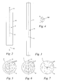
- Fig. 1 shows in an overview representation of a brush cutter 2, which is supported by an operator 10 and guided by hand.
- the brushcutter 2 comprises a drive motor 9, which may be embodied as an electric motor or as an internal combustion engine and which is arranged on a user-side end of a guide tube 8.
- a cutting head 13 is arranged with a mowing thread 1 projecting radially thereof and rotatably supported.
- drive shaft of the cutting head 13 is driven together with the cutting line 1 by means of the drive motor 9 about a rotation axis 7 rotating. The forces acting on the cutting line 1 centrifugal forces direct this in the radial direction.
- the operator 10 guides the cutting head 13 together with the cutting line 1 to a surface to be machined such that the radially aligned cutting thread 1 impinges on the material to be mowed, such as grass or the like, as a result of its circulating movement.
- the grass or other plants are mowed here.
- the cutting line 1 is loaded as a result of the centrifugal forces acting in its longitudinal axis lying radially to the axis of rotation 7. In addition, he can split across it.
- Fig. 2 shows a schematic side view of a section of a thread blank 6, which extends along a longitudinal axis 5.
- a detail marked V is in enlarged detail in Fig. 5 shown, according to which the thread blank 6 is formed from a plastic 4, in which a plurality of particles 3 is embedded.
- the particles 3 are formed in the form of flat platelets, which are shown here schematically for the sake of simplicity as circular discs. In practice, they have an irregular shape. In any case, however, they have an at least approximately flat, flat shape, wherein the extent of the particles 3 in their plane has a size in the micrometer range or smaller.
- the particles 3 are preferably designed as nanoparticles with a maximum extent in the sub-micron range, namely in the nanometer range, wherein the extent of the particles 3 in their plane has a size of about 500 nm to about 1000 nm.
- the thickness of the particles 3 is in comparison to several orders of magnitude smaller and is in a range of 0.5 nm to 2 nm and in the illustrated embodiment is about 1 nm.
- the proportion by weight of the particles 3 in the thread blank 6 and also in the later produced therefrom 1 ( Fig. 1 . 3 ) is advantageously in the range of 1% to 5% inclusive, and more preferably in the range of 2% to 3% inclusive.
- As the material for the plastic 4 polyamide is selected.
- a sheet silicate is chosen as the material. This is formed in the illustrated embodiment of bentonite, which is split by phase separation, intercalation and subsequent exfoliation into individual platelets of the aforementioned size. The individual platelet-shaped particles 3 are uniformly distributed in the plastic 4.
- the thread blank 6 is after Fig. 2 extruded, wherein the particles 3 are uniformly distributed in the extruded state not only in place, but also in their spatial orientation, so have no significant spatial preference orientation.
- the particles 3 are uniformly distributed in the extruded state not only in place, but also in their spatial orientation, so have no significant spatial preference orientation.
- a significant proportion of the platelet-shaped particles 3 spans planes that are transverse to the longitudinal axis 5. As a result, they can exert no reinforcing effect in the direction of the longitudinal axis 5 or even develop a weakening effect in this direction.
- Fig. 6 shows an enlarged view of the detail VI after Fig. 3 according to which the platelet-shaped particles 3 embedded in the plastic 4 are aligned at least primarily in the direction of the longitudinal axis 5.
- This alignment is achieved by stretching the thread blank 6 (FIG. Fig. 2 ) to the cutting line 1 ( Fig. 3 ) brought about.
- the polymeric chain molecules of the plastic 4 orientate in the direction of the longitudinal axis 5 and at the same time lead to a reorientation of the stochastically distributed particles 3 Fig. 5 in the state after Fig. 6 cause.
- Fig. 7 shows an enlarged view of the detail VII after Fig. 4 in a cross-sectional view of the cutting line 1.
- the particles 3 are shown in their reoriented by the stretching operation position. From the synopsis of 6 and 7 shows that each individual platelet-shaped particles 3 spans a plane parallel to the longitudinal axis 5 and otherwise either radially or tangentially or secantally thereto. In this particular plane, the particles 3 act to reinforce the plastic 4. Since the particles 3 are all at least approximately parallel to the longitudinal axis 5 (FIG. Fig. 6 ), the cutting line 1 is reinforced in the direction of its longitudinal axis 5.
- the mower 1 is reinforced in terms of its main operating and wear loads in such a way that a significantly increased life is observed.
Abstract
Description
- Bei handgeführten, motorisch angetriebenen Freischneidern kommt ein schnell rotierender Schneidkopf mit einem Mähfaden zum Einsatz. Infolge der wirkenden Fliehkräfte richtet sich der Mähfaden radial zur Drehachse aus und schneidet Gras oder andere Pflanzenteile ab. Die hauptsächliche Belastung des Mähfadens entsteht durch radial wirkende Fliehkräfte, die auf das Fadenmaterial in dessen Axialrichtung einwirken.
- Damit sich der Mähfaden unter Betriebslast nicht zu sehr dehnt oder gar reißt, wird ein extrudierter Kunststofffaden als Rohling hergestellt und im Anschluss an den Extrusionsprozess unter plastischer Verformung gereckt. Beim Recken orientieren sich die polymeren Kettenmoleküle in der Längsrichtung. Bei hohen Reckverhältnissen werden hohe Längssteifigkeit und -festigkeit erzielt, was Dehnung und Abrissneigung reduziert.
- Eine weitere Belastung des Mähfadens besteht aber im Verschleiß, der durch das Auf treffen des Mähfadens auf das Schnittgut oder auf härtere Gegenstände wie Steine oder dergleichen entsteht. Als Schadensbild ist insbesondere ein Aufspleißen des Mähfadens zu beobachten. Das Aufspleißen ist auf mangelhafte Festigkeit quer zur Fadenlängsrichtung zurückzuführen. Die infolge der Reckung in Längsrichtung ausgerichteten Kettenmoleküle bringen als Nachteil mit sich, dass die Querfestigkeit innerhalb des Mähfadens verringert wird, was die Neigung zum Aufspleißen begünstigt.
- Der Erfindung liegt die Aufgabe zugrunde, einen gattungsgemäßen Mähfaden derart weiterzubilden, dass dessen Verschleißfestigkeit erhöht ist.
- Diese Aufgabe wird durch einen Mähfaden mit den Merkmalen des Anspruchs 1 gelöst.
- Der Erfindung liegt des Weiteren die Aufgabe zugrunde, ein Verfahren zur Herstellung eines solchen Mähfadens anzugeben, mittels dessen der Mähfaden eine erhöhte Verschleißfestigkeit erhält.
- Diese Aufgabe wird durch ein Verfahren mit den Merkmalen des Anspruchs 6 gelöst.
- Beim erfindungsgemäßen Mähfaden und auch beim zugehörigen Herstellverfahren ist vorgesehen, dass ein Kunststoff mit einer Füllung aus plättchenförmigen Partikeln zum Einsatz kommt. Aus diesem mit plättchenförmigen Partikeln gefüllten Kunststoff wird ein Fadenrohling extrudiert und anschließend im erstarrten Zustand in Richtung seiner Längsachse unter plastischer Verformung derart gereckt, dass sich die eingebetteten Partikel zumindest vorrangig in Richtung der Längsachse ausrichten. Es entsteht ein Mähfaden, innerhalb dessen die plättchenförmigen, im Wesentlichen ebenen Partikel jeweils in einer Ebene liegen, die parallel zur Längsachse des Mähfadens ausgerichtet ist.
- Die vorgenannte Ausrichtung der Partikel infolge des Reckvorganges führt zu einer gezielten Verstärkung des Kunststoffmaterials in der Längsrichtung des Mähfadens und auch quer dazu. Dies beruht auf der Erkenntnis, dass die plättchenförmigen Partikel im Kunststoff eine richtungsabhängige Verstärkungswirkung entfalten, die sich im Wesentlichen nur in der Ebene der einzelnen flächigen Partikel auswirkt. Bei einer unorientierten Anordnung der flächigen Partikel liegt ein erheblicher Anteil davon quer zur Längsachse des Mähfadens und kann in Richtung der Längsachse des Mähfadens, also in Richtung der Fliehkraftbelastung nicht wirken. Möglicherweise können sie die Tragfähigkeit des gefüllten Kunststoffes sogar herabsetzen. Durch den Reckvorgang werden aber die zunächst wahllos räumlich verteilten Partikel einschließlich derjenigen, die unerwünscht quer zur Längsachse des Mähfadens liegen, umorientiert und gemeinsam mit den polymeren Kettenmolekülen in der Axialrichtung des Mähfadens ausgerichtet. Einerseits wird hierdurch der Mähfaden in seiner Axialrichtung durch die flächigen Partikel verstärkt, wobei diese Verstärkung unterstützend auf die durch den Reckvorgang in Axialrichtung ausgerichteten polymeren Kettenmoleküle einwirkt. Der Mähfaden erhält in Längs- bzw. Axialrichtung eine erhöhte Steifigkeit und auch Festigkeit. Da die flächigen, plättchenförmigen Partikel aber gleichzeitig auch eine Erstreckung in Radial- bzw. Tangentialrichtung zur Längsachse des Mähfadens aufweisen, beseitigen sie den beim Stand der Technik zu beobachtenden Nachteil der Aufspleißneigung. Ein Aufspalten bzw. Aufspleißen des Fadenquerschnitts wird durch die auch in Querrichtung wirkende Haltekraft der Partikel zuverlässig vermieden. Der erfindungsgemäße Mähfaden ist hinsichtlich seiner Verschleißfestigkeit deutlich verbessert.
- Die plättchenförmigen Partikel sind zweckmäßig als Nanopartikel ausgebildet und weisen bevorzugt in ihrer Ebene eine Größe von 500 nm bis 1000 nm und eine Dicke von 0,5 nm bis 2 nm auf. Vorteilhaft sind sie durch ein Schichtsilikat gebildet. Der Gewichtsanteil der Partikel im Mähfaden liegt zweckmäßig in einem Bereich von einschließlich 1 % bis einschließlich 5 % und bevorzugt in einem Bereich von einschließlich 2 % bis einschließlich 3 %. Als Kunststoffmaterial, in das die Partikel eingebettet sind, hat sich Polyamid als zweckmäßig herausgestellt.
- Ein Ausführungsbeispiel der Erfindung ist nachfolgend anhand der Zeichnung näher beschrieben. Es zeigen:
- Fig. 1
- in einer Übersichtsdarstellung einen handgeführten Freischneider mit einem erfindungsgemäß ausgeführten Mähfaden;
- Fig. 2
- in einer schematischen Seitenansicht einen Ausschnitt aus einem mit Nano- partikeln gefüllten, extrudierten Kunststofffadenrohling;
- Fig. 3
- den zum erfindungsgemäßen Mähfaden gereckten Fadenrohling nach
Fig. 2 ; - Fig. 4
- eine Querschnittsdarstellung des Mähfadens nach
Fig. 3 ; - Fig. 5
- eine vergrößerte Darstellung der Einzelheit V nach
Fig. 2 mit im extrudierten Zustand unorientiert im Kunststoff eingebetteten plättchenförmigen Nano- partikeln; - Fig. 6
- eine vergrößerte Darstellung der Einzelheit VI nach
Fig. 3 mit in Richtung der Längsachse ausgerichteten Nanopartikeln; - Fig. 7
- eine vergrößerte Darstellung der Einzelheit VII nach
Fig. 4 mit Einzelheiten zur räumlichen Orientierung der plättchenförmigen Nanopartikel im Quer- schnitt des Mähfadens. -
Fig. 1 zeigt in einer Übersichtsdarstellung einen Freischneider 2, der von einer Bedienperson 10 getragen und von Hand geführt wird. Der Freischneider 2 umfasst einen Antriebsmotor 9, der als Elektromotor oder als Verbrennungsmotor ausgeführt sein kann und der an einem benutzerseitigen Ende eines Führungsrohres 8 angeordnet ist. Am gegenüberliegenden Ende des Führungsrohres 8 ist ein Schneidkopf 13 mit einem radial davon hervorstehenden Mähfaden 1 angeordnet und drehbar gelagert. Über eine nicht dargestellte, im Führungsrohr 8 gelagerte Antriebswelle wird der Schneidkopf 13 zusammen mit dem Mähfaden 1 mittels des Antriebsmotors 9 um eine Drehachse 7 drehend angetrieben. Die hierbei auf den Mähfaden 1 wirkenden Fliehkräfte richten diesen in radialer Richtung aus. Die Bedienperson 10 führt den Schneidkopf 13 mitsamt dem Mähfaden 1 derart an eine zu bearbeitende Oberfläche, dass der radial ausgerichtete Mähfaden 1 infolge seiner Umlaufbewegung auf das zu mähende Gut wie Gras oder dergleichen auftrifft. Das Gras oder andere Pflanzen werden hierbei abgemäht. Der Mähfaden 1 wird infolge der wirkenden Fliehkräfte in seiner radial zur Drehachse 7 liegenden Längsachse belastet. Außerdem kann er quer dazu aufspleißen. -
Fig. 2 zeigt in einer schematischen Seitenansicht einen Ausschnitt eines Fadenrohlings 6, der sich entlang einer Längsachse 5 erstreckt. Eine mit V gekennzeichnete Einzelheit ist in vergrößerter Detaildarstellung inFig. 5 gezeigt, demnach der Fadenrohling 6 aus einem Kunststoff 4 gebildet ist, in den eine Vielzahl von Partikeln 3 eingebettet ist. Die Partikel 3 sind in Form von ebenen Plättchen ausgebildet, die hier der Einfachheit halber schematisch als Kreisscheiben dargestellt sind. In der Praxis weisen sie eine unregelmäßige Form auf. In jedem Falle aber haben sie eine zumindest näherungsweise ebene, flache Form, wobei die Erstreckung der Partikel 3 in ihrer Ebene eine Größe im Mikrometerbereich oder kleiner aufweist. Bevorzugt sind die Partikel 3 als Nanopartikel mit einer maximalen Erstreckung im Sub-Mikrometerbereich, nämlich im Nanometerbereich ausgebildet, wobei die Erstreckung der Partikel 3 in ihrer Ebene eine Größe von circa 500 nm bis circa 1000 nm aufweist. Die Dicke der Partikel 3 ist im Vergleich hierzu um mehrere Größenordnungen geringer und liegt in einem Bereich von 0,5 nm bis 2 nm und beträgt im gezeigten Ausführungsbeispiel etwa 1 nm. Der Gewichtsanteil der Partikel 3 im Fadenrohling 6 und auch im später daraus hergestellten Mähfaden 1 (Fig. 1 ,3 ) liegt vorteilhaft in einem Bereich von einschließlich 1 % bis einschließlich 5 % und insbesondere in einem Bereich von einschließlich 2 % bis einschließlich 3 %. Als Material für den Kunststoff 4 ist Polyamid gewählt. - Für die Partikel 3 ist als Material ein Schichtsilikat gewählt. Dieses ist im gezeigten Ausführungsbeispiel aus Bentonit gebildet, welches durch Phasenseparation, Interkalation und anschließende Exfoliation in einzelne Plättchen der vorgenannten Größe aufgespalten ist. Die einzelnen plättchenförmigen Partikel 3 sind gleichmäßig im Kunststoff 4 verteilt.
- Aus dem Material nach
Fig. 5 wird der Fadenrohling 6 nachFig. 2 extrudiert, wobei die Partikel 3 im extrudierten Zustand nicht nur in ihrem Ort, sondern auch in ihrer räumlichen Orientierung gleichmäßig verteilt sind, also keine nennenswerte räumliche Vorzugsorientierung aufweisen. Insbesondere ist in der Darstellung nachFig. 5 zu erkennen, dass ein erheblicher Anteil der plättchenförmigen Partikel 3 Ebenen aufspannt, die quer zur Längsachse 5 liegen. Hierdurch können sie keine Verstärkungswirkung in Richtung der Längsachse 5 ausüben oder sogar eine schwächende Wirkung in dieser Richtung entfalten. - Nach dem Extrusionsvorgang des Fadenrohlings 6 wird dieser im erstarrten Zustand in Richtung seiner Längsachse 5 durch Aufbringen einer Längskraft entsprechend den Pfeilen 11, 12 nach
Fig. 2 unter plastischer Verformung gereckt, so dass der Mähfaden 1 gebildet wird, von dem ein Ausschnitt schematisch inFig. 3 dargestellt ist. Der Mähfaden 1 nachFig. 3 ist gegenüber dem Fadenrohling 6 nachFig. 2 gelängt, weist aber eine geringere Querschnittsfläche auf. Eine Querschnittsansicht des Mähfadens 1 quer zur Längsachse 5 ist inFig. 4 dargestellt, demnach ein kreisscheibenförmiger Querschnitt vorgesehen ist. Es kann aber auch eine abweichende Querschnittsform zweckmäßig sein. -
Fig. 6 zeigt eine vergrößerte Darstellung der Einzelheit VI nachFig. 3 , demnach die in den Kunststoff 4 eingebetteten plättchenförmigen Partikel 3 zumindest vorrangig in Richtung der Längsachse 5 ausgerichtet sind. Diese Ausrichtung wird durch das Recken des Fadenrohlings 6 (Fig. 2 ) zum Mähfaden 1 (Fig. 3 ) herbeigeführt. Beim Recken orientieren sich die polymeren Kettenmoleküle des Kunststoffs 4 in Richtung der Längsachse 5 und führen dabei gleichzeitig eine Umorientierung der stochastisch verteilten Partikel 3 nachFig. 5 in den Zustand nachFig. 6 herbei. -
Fig. 7 zeigt eine vergrößerte Darstellung der Einzelheit VII nachFig. 4 in einer Querschnittsdarstellung des Mähfadens 1. Auch hier sind die Partikel 3 in ihrer durch den Reckvorgang umorientierten Lage gezeigt. Aus der Zusammenschau derFig. 6 und 7 ergibt sich, dass jeder einzelne plättchenförmige Partikel 3 eine Ebene aufspannt, die parallel zur Längsachse 5 und im Übrigen entweder radial oder tangential bzw. sekantenförmig dazu liegt. In dieser jeweiligen Ebene wirken die Partikel 3 verstärkend auf den Kunststoff 4. Da die Partikel 3 sämtlich zumindest näherungsweise parallel zur Längsachse 5 (Fig. 6 ) liegen, ist der Mähfaden 1 in Richtung seiner Längsachse 5 verstärkt. Außerdem ergibt sich aus der Zusammenschau derFig. 4 und 7 , dass sämtliche Partikel 3 in ihrer jeweiligen Ebene radial bzw. tangential oder sekantenförmig zur Längsachse 5 liegen und damit den Querschnitt des Mähfadens 1 verstärken. Der Querschnitt des Mähfadens 1 kann sich deshalb nicht oder nur ein eingeschränkt aufspalten bzw. aufspleißen. - Insgesamt ist damit der Mähfaden 1 hinsichtlich seiner hauptsächlich auftretenden Betriebs- und Verschleißlasten in einer Weise verstärkt, dass eine deutlich erhöhte Lebensdauer zu beobachten ist.
Claims (6)
- Mähfaden (1) für einen handgeführten Freischneider (2),
dadurch gekennzeichnet, dass der Mähfaden (1) aus einem mit plättchenförmigen Partikeln (3) gefüllten Kunststoff (4) gebildet und derart gereckt ist, dass die plättchenförmigen Partikel (3) zumindest vorrangig in Richtung einer Längsachse (5) des Mähfadens (1) ausgerichtet sind. - Mähfaden nach Anspruch 1,
dadurch gekennzeichnet, dass die plättchenförmigen Partikel (3) Nanopartikel sind und insbesondere in ihrer Ebene eine Größe von 500 nm bis 1000 nm und eine Dicke von 0,5 nm bis 2 nm aufweisen. - Mähfaden nach Anspruch 1 oder 2,
dadurch gekennzeichnet, dass die Partikel (3) durch ein Schichtsilikat gebildet sind. - Mähfaden nach einem der Ansprüche 1 bis 3,
dadurch gekennzeichnet, dass der Gewichtsanteil der Partikel (3) im Mähfaden (1) in einem Bereich von einschließlich 1 % bis einschließlich 5 % und bevorzugt in einem Bereich von einschließlich 2 % bis einschließlich 3 % liegt. - Mähfaden nach einem der Ansprüche 1 bis 4,
dadurch gekennzeichnet, dass der Kunststoff (4) Polyamid ist. - Verfahren zur Herstellung eines Mähfaden (1) nach einem der Ansprüche 1 bis 5, umfassend folgende Verfahrensschritte:- Ein Kunststoff (4) wird mit plättchenförmigen Partikeln (3) gefüllt;- der gefüllte Kunststoff (4) wird in Form eines Fadenrohlings (6) extrudiert;- der Fadenrohling (6) wird im erstarrten Zustand in Richtung seiner Längsachse (5) unter plastischer Verformung derart gereckt, dass sich die eingebetteten Partikel (3) zumindest vorrangig in Richtung der Längsachse (5) ausrichten.
Applications Claiming Priority (1)
| Application Number | Priority Date | Filing Date | Title |
|---|---|---|---|
| DE102009050593A DE102009050593A1 (de) | 2009-10-24 | 2009-10-24 | Mähfaden für einen Freischneider und Verfahren zur Herstellung eines solchen Mähfadens |
Publications (3)
| Publication Number | Publication Date |
|---|---|
| EP2314145A2 true EP2314145A2 (de) | 2011-04-27 |
| EP2314145A3 EP2314145A3 (de) | 2011-11-02 |
| EP2314145B1 EP2314145B1 (de) | 2017-08-23 |
Family
ID=43494931
Family Applications (1)
| Application Number | Title | Priority Date | Filing Date |
|---|---|---|---|
| EP10013250.5A Active EP2314145B1 (de) | 2009-10-24 | 2010-10-02 | Mähfaden für einen Freischneider und Verfahren zur Herstellung eines solchen Mähfadens |
Country Status (4)
| Country | Link |
|---|---|
| US (1) | US20110098399A1 (de) |
| EP (1) | EP2314145B1 (de) |
| CN (1) | CN102084752A (de) |
| DE (1) | DE102009050593A1 (de) |
Cited By (1)
| Publication number | Priority date | Publication date | Assignee | Title |
|---|---|---|---|---|
| CN102925444A (zh) * | 2012-11-13 | 2013-02-13 | 南京医科大学 | 膀胱癌的血清miRNA生物标志物及其表达量检测方法 |
Families Citing this family (1)
| Publication number | Priority date | Publication date | Assignee | Title |
|---|---|---|---|---|
| CN106465603A (zh) * | 2015-08-18 | 2017-03-01 | 苏州宝时得电动工具有限公司 | 切割元件及装配该切割元件的打草机 |
Family Cites Families (11)
| Publication number | Priority date | Publication date | Assignee | Title |
|---|---|---|---|---|
| US5524350A (en) * | 1994-07-15 | 1996-06-11 | Glassmaster Company | Cutting line filled with inorganic grit material |
| US5761816A (en) * | 1996-05-31 | 1998-06-09 | Morabit; Vincent D. | Aerodynamic cutting string |
| JPH10108523A (ja) * | 1996-10-07 | 1998-04-28 | Taisei Kozai Kk | 草刈り用ナイロンカッター |
| FR2760596B1 (fr) * | 1997-03-14 | 1999-04-02 | Speed France | Fil de coupe composite pour debroussailleuses et taille-bordures |
| FR2789094B1 (fr) * | 1999-02-03 | 2001-05-25 | Speed France | Fil de coupe ou fil de peche en matiere synthetique |
| FR2796086B1 (fr) * | 1999-07-06 | 2002-03-15 | Rhodianyl | Articles files resistant a l'abrasion |
| US6560878B2 (en) * | 2000-04-12 | 2003-05-13 | Shakespeare Company, Llc | Multi-component, extruded vegetation cutting line |
| US20030033960A1 (en) * | 2001-08-17 | 2003-02-20 | Hudzinski Michael E. | Line trimmer, biodegradable trim line for use therewith, and method of making same |
| EP1511372B1 (de) * | 2002-06-07 | 2010-08-04 | Speed France S.A.S. | Mähfaden für vegetation-mähapparat |
| FR2854764B1 (fr) * | 2003-05-14 | 2006-06-23 | Speed France | Nouveau fil de coupe pour appareils tels que taille-bordures ou debroussailleuses |
| FR2886949B1 (fr) * | 2005-06-10 | 2007-08-03 | Rhodia Chimie Sa | Fils, filaments et fibres polyamide a proprietes ameliorees |
-
2009
- 2009-10-24 DE DE102009050593A patent/DE102009050593A1/de not_active Withdrawn
-
2010
- 2010-08-18 US US12/859,190 patent/US20110098399A1/en not_active Abandoned
- 2010-10-02 EP EP10013250.5A patent/EP2314145B1/de active Active
- 2010-10-22 CN CN2010105337738A patent/CN102084752A/zh active Pending
Non-Patent Citations (1)
| Title |
|---|
| None |
Cited By (1)
| Publication number | Priority date | Publication date | Assignee | Title |
|---|---|---|---|---|
| CN102925444A (zh) * | 2012-11-13 | 2013-02-13 | 南京医科大学 | 膀胱癌的血清miRNA生物标志物及其表达量检测方法 |
Also Published As
| Publication number | Publication date |
|---|---|
| EP2314145B1 (de) | 2017-08-23 |
| DE102009050593A1 (de) | 2011-04-28 |
| EP2314145A3 (de) | 2011-11-02 |
| US20110098399A1 (en) | 2011-04-28 |
| CN102084752A (zh) | 2011-06-08 |
Similar Documents
| Publication | Publication Date | Title |
|---|---|---|
| DE1159818B (de) | Verfahren zur Herstellung elastischer Drahtseile und nach diesem Verfahren erhaltene Drahtseile | |
| DE202016102177U1 (de) | Vorrichtung zum Einsetzen künstlicher Grasstränge in den Boden | |
| DE2619086A1 (de) | Verstaerkungsseil fuer elastomere erzeugnisse, verfahren und vorrichtung zur herstellung | |
| EP3033446B1 (de) | Vorrichtung und verfahren zur isolierung von bastrinde und holzkörper aus einem bastpflanzenstängel | |
| DE602005002028T2 (de) | Verfahren und maschine für die bildung von rundballen von faserpflanzen, insbesondere flachs, hanf und sisal | |
| DE2928843A1 (de) | Rotationsmesser | |
| DE2353895B2 (de) | Vorrichtung zum zerschneiden von glasstraengen | |
| EP2170586B1 (de) | Vorrichtung und verfahren zur bereitstellung von abgelängten rovings sowie maschine zur verstärkung eines textilen halbzeugs | |
| DE2948422C2 (de) | Kraftübertragungsriemen | |
| EP3006228B1 (de) | Hybridkord zur Verwendung als Festigkeitsträger in einem Bauteil eines Fahrzeugluftreifens und Fahrzeugluftreifen | |
| EP2314145B1 (de) | Mähfaden für einen Freischneider und Verfahren zur Herstellung eines solchen Mähfadens | |
| DE3011936A1 (de) | Luftreifen von grosser haltbarkeit | |
| DE102012101721B4 (de) | Verwendung eines Wickelrahmens zur Herstellung eines Faserverbundwerkstoffbauteils | |
| DE19715552C1 (de) | Schneid- und Entschäbungssystem für ein Ernten und zum Behandeln geernteter Hanfpflanzen | |
| DE102007007242B4 (de) | Mähmaschine | |
| EP3370498B1 (de) | Längsentblatter und entsprechende rübenerntemaschine | |
| EP3210752B1 (de) | Geschnittener rotationskörper und verfahren zur herstellung eines rotationskörpers | |
| EP3323634B1 (de) | Hybridkord zur verwendung als festigkeitsträger in einem bauteil eines fahrzeugluftreifens und fahrzeugluftreifen | |
| DE102020103294A1 (de) | Antriebsmittel für Förderbänder, insbesondere landwirtschaftlicher Maschinen und Verfahren zu dessen Herstellung | |
| DE102015104330B3 (de) | Vorrichtung zum Schneiden von Stapelfasern | |
| EP3400131A1 (de) | Faserverbundbauteil und strukturbauteil sowie herstellungsverfahren | |
| EP1378466A2 (de) | Rollenantriebseinheit | |
| DE2929702A1 (de) | Selbstausrichtender kraftuebertragungsriemen, verfahren zu seiner herstellung und antriebssystem zur verwendung desselben | |
| CH634358A5 (de) | Abstreifer zum entfernen von unterwindungen von dem unterwindebereich einer ringspinn- oder -zwirnspindel. | |
| EP3455038B1 (de) | Verfahren zum trennen eines trockenen faserverbundgeleges, insbesondere für eine windenergieanlage |
Legal Events
| Date | Code | Title | Description |
|---|---|---|---|
| PUAI | Public reference made under article 153(3) epc to a published international application that has entered the european phase |
Free format text: ORIGINAL CODE: 0009012 |
|
| AK | Designated contracting states |
Kind code of ref document: A2 Designated state(s): AL AT BE BG CH CY CZ DE DK EE ES FI FR GB GR HR HU IE IS IT LI LT LU LV MC MK MT NL NO PL PT RO RS SE SI SK SM TR |
|
| AX | Request for extension of the european patent |
Extension state: BA ME |
|
| PUAL | Search report despatched |
Free format text: ORIGINAL CODE: 0009013 |
|
| AK | Designated contracting states |
Kind code of ref document: A3 Designated state(s): AL AT BE BG CH CY CZ DE DK EE ES FI FR GB GR HR HU IE IS IT LI LT LU LV MC MK MT NL NO PL PT RO RS SE SI SK SM TR |
|
| AX | Request for extension of the european patent |
Extension state: BA ME |
|
| RIC1 | Information provided on ipc code assigned before grant |
Ipc: D01F 6/00 20060101ALI20110926BHEP Ipc: A01D 34/416 20060101AFI20110926BHEP |
|
| 17P | Request for examination filed |
Effective date: 20120118 |
|
| 17Q | First examination report despatched |
Effective date: 20150130 |
|
| GRAP | Despatch of communication of intention to grant a patent |
Free format text: ORIGINAL CODE: EPIDOSNIGR1 |
|
| INTG | Intention to grant announced |
Effective date: 20170331 |
|
| GRAS | Grant fee paid |
Free format text: ORIGINAL CODE: EPIDOSNIGR3 |
|
| GRAA | (expected) grant |
Free format text: ORIGINAL CODE: 0009210 |
|
| AK | Designated contracting states |
Kind code of ref document: B1 Designated state(s): AL AT BE BG CH CY CZ DE DK EE ES FI FR GB GR HR HU IE IS IT LI LT LU LV MC MK MT NL NO PL PT RO RS SE SI SK SM TR |
|
| REG | Reference to a national code |
Ref country code: GB Ref legal event code: FG4D Free format text: NOT ENGLISH |
|
| REG | Reference to a national code |
Ref country code: CH Ref legal event code: EP |
|
| REG | Reference to a national code |
Ref country code: AT Ref legal event code: REF Ref document number: 920273 Country of ref document: AT Kind code of ref document: T Effective date: 20170915 |
|
| REG | Reference to a national code |
Ref country code: IE Ref legal event code: FG4D Free format text: LANGUAGE OF EP DOCUMENT: GERMAN |
|
| REG | Reference to a national code |
Ref country code: DE Ref legal event code: R096 Ref document number: 502010014038 Country of ref document: DE |
|
| REG | Reference to a national code |
Ref country code: FR Ref legal event code: PLFP Year of fee payment: 8 |
|
| REG | Reference to a national code |
Ref country code: NL Ref legal event code: MP Effective date: 20170823 |
|
| REG | Reference to a national code |
Ref country code: LT Ref legal event code: MG4D |
|
| PG25 | Lapsed in a contracting state [announced via postgrant information from national office to epo] |
Ref country code: LT Free format text: LAPSE BECAUSE OF FAILURE TO SUBMIT A TRANSLATION OF THE DESCRIPTION OR TO PAY THE FEE WITHIN THE PRESCRIBED TIME-LIMIT Effective date: 20170823 Ref country code: NO Free format text: LAPSE BECAUSE OF FAILURE TO SUBMIT A TRANSLATION OF THE DESCRIPTION OR TO PAY THE FEE WITHIN THE PRESCRIBED TIME-LIMIT Effective date: 20171123 Ref country code: NL Free format text: LAPSE BECAUSE OF FAILURE TO SUBMIT A TRANSLATION OF THE DESCRIPTION OR TO PAY THE FEE WITHIN THE PRESCRIBED TIME-LIMIT Effective date: 20170823 Ref country code: HR Free format text: LAPSE BECAUSE OF FAILURE TO SUBMIT A TRANSLATION OF THE DESCRIPTION OR TO PAY THE FEE WITHIN THE PRESCRIBED TIME-LIMIT Effective date: 20170823 Ref country code: SE Free format text: LAPSE BECAUSE OF FAILURE TO SUBMIT A TRANSLATION OF THE DESCRIPTION OR TO PAY THE FEE WITHIN THE PRESCRIBED TIME-LIMIT Effective date: 20170823 Ref country code: FI Free format text: LAPSE BECAUSE OF FAILURE TO SUBMIT A TRANSLATION OF THE DESCRIPTION OR TO PAY THE FEE WITHIN THE PRESCRIBED TIME-LIMIT Effective date: 20170823 |
|
| PG25 | Lapsed in a contracting state [announced via postgrant information from national office to epo] |
Ref country code: RS Free format text: LAPSE BECAUSE OF FAILURE TO SUBMIT A TRANSLATION OF THE DESCRIPTION OR TO PAY THE FEE WITHIN THE PRESCRIBED TIME-LIMIT Effective date: 20170823 Ref country code: BG Free format text: LAPSE BECAUSE OF FAILURE TO SUBMIT A TRANSLATION OF THE DESCRIPTION OR TO PAY THE FEE WITHIN THE PRESCRIBED TIME-LIMIT Effective date: 20171123 Ref country code: ES Free format text: LAPSE BECAUSE OF FAILURE TO SUBMIT A TRANSLATION OF THE DESCRIPTION OR TO PAY THE FEE WITHIN THE PRESCRIBED TIME-LIMIT Effective date: 20170823 Ref country code: IS Free format text: LAPSE BECAUSE OF FAILURE TO SUBMIT A TRANSLATION OF THE DESCRIPTION OR TO PAY THE FEE WITHIN THE PRESCRIBED TIME-LIMIT Effective date: 20171223 Ref country code: GR Free format text: LAPSE BECAUSE OF FAILURE TO SUBMIT A TRANSLATION OF THE DESCRIPTION OR TO PAY THE FEE WITHIN THE PRESCRIBED TIME-LIMIT Effective date: 20171124 Ref country code: LV Free format text: LAPSE BECAUSE OF FAILURE TO SUBMIT A TRANSLATION OF THE DESCRIPTION OR TO PAY THE FEE WITHIN THE PRESCRIBED TIME-LIMIT Effective date: 20170823 Ref country code: PL Free format text: LAPSE BECAUSE OF FAILURE TO SUBMIT A TRANSLATION OF THE DESCRIPTION OR TO PAY THE FEE WITHIN THE PRESCRIBED TIME-LIMIT Effective date: 20170823 |
|
| PG25 | Lapsed in a contracting state [announced via postgrant information from national office to epo] |
Ref country code: RO Free format text: LAPSE BECAUSE OF FAILURE TO SUBMIT A TRANSLATION OF THE DESCRIPTION OR TO PAY THE FEE WITHIN THE PRESCRIBED TIME-LIMIT Effective date: 20170823 Ref country code: DK Free format text: LAPSE BECAUSE OF FAILURE TO SUBMIT A TRANSLATION OF THE DESCRIPTION OR TO PAY THE FEE WITHIN THE PRESCRIBED TIME-LIMIT Effective date: 20170823 Ref country code: CZ Free format text: LAPSE BECAUSE OF FAILURE TO SUBMIT A TRANSLATION OF THE DESCRIPTION OR TO PAY THE FEE WITHIN THE PRESCRIBED TIME-LIMIT Effective date: 20170823 |
|
| REG | Reference to a national code |
Ref country code: DE Ref legal event code: R097 Ref document number: 502010014038 Country of ref document: DE |
|
| PG25 | Lapsed in a contracting state [announced via postgrant information from national office to epo] |
Ref country code: SK Free format text: LAPSE BECAUSE OF FAILURE TO SUBMIT A TRANSLATION OF THE DESCRIPTION OR TO PAY THE FEE WITHIN THE PRESCRIBED TIME-LIMIT Effective date: 20170823 Ref country code: SM Free format text: LAPSE BECAUSE OF FAILURE TO SUBMIT A TRANSLATION OF THE DESCRIPTION OR TO PAY THE FEE WITHIN THE PRESCRIBED TIME-LIMIT Effective date: 20170823 Ref country code: EE Free format text: LAPSE BECAUSE OF FAILURE TO SUBMIT A TRANSLATION OF THE DESCRIPTION OR TO PAY THE FEE WITHIN THE PRESCRIBED TIME-LIMIT Effective date: 20170823 Ref country code: MC Free format text: LAPSE BECAUSE OF FAILURE TO SUBMIT A TRANSLATION OF THE DESCRIPTION OR TO PAY THE FEE WITHIN THE PRESCRIBED TIME-LIMIT Effective date: 20170823 Ref country code: IT Free format text: LAPSE BECAUSE OF FAILURE TO SUBMIT A TRANSLATION OF THE DESCRIPTION OR TO PAY THE FEE WITHIN THE PRESCRIBED TIME-LIMIT Effective date: 20170823 |
|
| REG | Reference to a national code |
Ref country code: CH Ref legal event code: PL |
|
| PLBE | No opposition filed within time limit |
Free format text: ORIGINAL CODE: 0009261 |
|
| STAA | Information on the status of an ep patent application or granted ep patent |
Free format text: STATUS: NO OPPOSITION FILED WITHIN TIME LIMIT |
|
| REG | Reference to a national code |
Ref country code: IE Ref legal event code: MM4A |
|
| PG25 | Lapsed in a contracting state [announced via postgrant information from national office to epo] |
Ref country code: LU Free format text: LAPSE BECAUSE OF NON-PAYMENT OF DUE FEES Effective date: 20171002 Ref country code: LI Free format text: LAPSE BECAUSE OF NON-PAYMENT OF DUE FEES Effective date: 20171031 Ref country code: CH Free format text: LAPSE BECAUSE OF NON-PAYMENT OF DUE FEES Effective date: 20171031 |
|
| 26N | No opposition filed |
Effective date: 20180524 |
|
| REG | Reference to a national code |
Ref country code: BE Ref legal event code: MM Effective date: 20171031 |
|
| PG25 | Lapsed in a contracting state [announced via postgrant information from national office to epo] |
Ref country code: SI Free format text: LAPSE BECAUSE OF FAILURE TO SUBMIT A TRANSLATION OF THE DESCRIPTION OR TO PAY THE FEE WITHIN THE PRESCRIBED TIME-LIMIT Effective date: 20170823 Ref country code: BE Free format text: LAPSE BECAUSE OF NON-PAYMENT OF DUE FEES Effective date: 20171031 |
|
| PG25 | Lapsed in a contracting state [announced via postgrant information from national office to epo] |
Ref country code: MT Free format text: LAPSE BECAUSE OF FAILURE TO SUBMIT A TRANSLATION OF THE DESCRIPTION OR TO PAY THE FEE WITHIN THE PRESCRIBED TIME-LIMIT Effective date: 20170823 |
|
| REG | Reference to a national code |
Ref country code: FR Ref legal event code: PLFP Year of fee payment: 9 |
|
| PG25 | Lapsed in a contracting state [announced via postgrant information from national office to epo] |
Ref country code: IE Free format text: LAPSE BECAUSE OF NON-PAYMENT OF DUE FEES Effective date: 20171002 |
|
| REG | Reference to a national code |
Ref country code: AT Ref legal event code: MM01 Ref document number: 920273 Country of ref document: AT Kind code of ref document: T Effective date: 20171002 |
|
| PG25 | Lapsed in a contracting state [announced via postgrant information from national office to epo] |
Ref country code: AT Free format text: LAPSE BECAUSE OF NON-PAYMENT OF DUE FEES Effective date: 20171002 |
|
| PG25 | Lapsed in a contracting state [announced via postgrant information from national office to epo] |
Ref country code: HU Free format text: LAPSE BECAUSE OF FAILURE TO SUBMIT A TRANSLATION OF THE DESCRIPTION OR TO PAY THE FEE WITHIN THE PRESCRIBED TIME-LIMIT; INVALID AB INITIO Effective date: 20101002 |
|
| PG25 | Lapsed in a contracting state [announced via postgrant information from national office to epo] |
Ref country code: CY Free format text: LAPSE BECAUSE OF NON-PAYMENT OF DUE FEES Effective date: 20170823 |
|
| PG25 | Lapsed in a contracting state [announced via postgrant information from national office to epo] |
Ref country code: MK Free format text: LAPSE BECAUSE OF FAILURE TO SUBMIT A TRANSLATION OF THE DESCRIPTION OR TO PAY THE FEE WITHIN THE PRESCRIBED TIME-LIMIT Effective date: 20170823 |
|
| PG25 | Lapsed in a contracting state [announced via postgrant information from national office to epo] |
Ref country code: TR Free format text: LAPSE BECAUSE OF FAILURE TO SUBMIT A TRANSLATION OF THE DESCRIPTION OR TO PAY THE FEE WITHIN THE PRESCRIBED TIME-LIMIT Effective date: 20170823 |
|
| PG25 | Lapsed in a contracting state [announced via postgrant information from national office to epo] |
Ref country code: PT Free format text: LAPSE BECAUSE OF FAILURE TO SUBMIT A TRANSLATION OF THE DESCRIPTION OR TO PAY THE FEE WITHIN THE PRESCRIBED TIME-LIMIT Effective date: 20170823 |
|
| PG25 | Lapsed in a contracting state [announced via postgrant information from national office to epo] |
Ref country code: AL Free format text: LAPSE BECAUSE OF FAILURE TO SUBMIT A TRANSLATION OF THE DESCRIPTION OR TO PAY THE FEE WITHIN THE PRESCRIBED TIME-LIMIT Effective date: 20170823 |
|
| PGFP | Annual fee paid to national office [announced via postgrant information from national office to epo] |
Ref country code: FR Payment date: 20221024 Year of fee payment: 13 |
|
| PGFP | Annual fee paid to national office [announced via postgrant information from national office to epo] |
Ref country code: GB Payment date: 20221018 Year of fee payment: 13 |
|
| PGFP | Annual fee paid to national office [announced via postgrant information from national office to epo] |
Ref country code: DE Payment date: 20231027 Year of fee payment: 14 |