EP2310847B1 - Corps multicellulaires auto-assemblés et procédés de production d une structure biologique tridimensionnelle utilisant ceux-ci - Google Patents
Corps multicellulaires auto-assemblés et procédés de production d une structure biologique tridimensionnelle utilisant ceux-ci Download PDFInfo
- Publication number
- EP2310847B1 EP2310847B1 EP09798534.5A EP09798534A EP2310847B1 EP 2310847 B1 EP2310847 B1 EP 2310847B1 EP 09798534 A EP09798534 A EP 09798534A EP 2310847 B1 EP2310847 B1 EP 2310847B1
- Authority
- EP
- European Patent Office
- Prior art keywords
- multicellular
- bodies
- cells
- filler
- multicellular bodies
- Prior art date
- Legal status (The legal status is an assumption and is not a legal conclusion. Google has not performed a legal analysis and makes no representation as to the accuracy of the status listed.)
- Not-in-force
Links
Images


Classifications
-
- C—CHEMISTRY; METALLURGY
- C12—BIOCHEMISTRY; BEER; SPIRITS; WINE; VINEGAR; MICROBIOLOGY; ENZYMOLOGY; MUTATION OR GENETIC ENGINEERING
- C12N—MICROORGANISMS OR ENZYMES; COMPOSITIONS THEREOF; PROPAGATING, PRESERVING, OR MAINTAINING MICROORGANISMS; MUTATION OR GENETIC ENGINEERING; CULTURE MEDIA
- C12N5/00—Undifferentiated human, animal or plant cells, e.g. cell lines; Tissues; Cultivation or maintenance thereof; Culture media therefor
- C12N5/0068—General culture methods using substrates
-
- A—HUMAN NECESSITIES
- A61—MEDICAL OR VETERINARY SCIENCE; HYGIENE
- A61F—FILTERS IMPLANTABLE INTO BLOOD VESSELS; PROSTHESES; DEVICES PROVIDING PATENCY TO, OR PREVENTING COLLAPSING OF, TUBULAR STRUCTURES OF THE BODY, e.g. STENTS; ORTHOPAEDIC, NURSING OR CONTRACEPTIVE DEVICES; FOMENTATION; TREATMENT OR PROTECTION OF EYES OR EARS; BANDAGES, DRESSINGS OR ABSORBENT PADS; FIRST-AID KITS
- A61F2/00—Filters implantable into blood vessels; Prostheses, i.e. artificial substitutes or replacements for parts of the body; Appliances for connecting them with the body; Devices providing patency to, or preventing collapsing of, tubular structures of the body, e.g. stents
- A61F2/02—Prostheses implantable into the body
-
- A—HUMAN NECESSITIES
- A61—MEDICAL OR VETERINARY SCIENCE; HYGIENE
- A61L—METHODS OR APPARATUS FOR STERILISING MATERIALS OR OBJECTS IN GENERAL; DISINFECTION, STERILISATION OR DEODORISATION OF AIR; CHEMICAL ASPECTS OF BANDAGES, DRESSINGS, ABSORBENT PADS OR SURGICAL ARTICLES; MATERIALS FOR BANDAGES, DRESSINGS, ABSORBENT PADS OR SURGICAL ARTICLES
- A61L27/00—Materials for grafts or prostheses or for coating grafts or prostheses
- A61L27/14—Macromolecular materials
- A61L27/22—Polypeptides or derivatives thereof, e.g. degradation products
- A61L27/222—Gelatin
-
- A—HUMAN NECESSITIES
- A61—MEDICAL OR VETERINARY SCIENCE; HYGIENE
- A61L—METHODS OR APPARATUS FOR STERILISING MATERIALS OR OBJECTS IN GENERAL; DISINFECTION, STERILISATION OR DEODORISATION OF AIR; CHEMICAL ASPECTS OF BANDAGES, DRESSINGS, ABSORBENT PADS OR SURGICAL ARTICLES; MATERIALS FOR BANDAGES, DRESSINGS, ABSORBENT PADS OR SURGICAL ARTICLES
- A61L27/00—Materials for grafts or prostheses or for coating grafts or prostheses
- A61L27/14—Macromolecular materials
- A61L27/22—Polypeptides or derivatives thereof, e.g. degradation products
- A61L27/225—Fibrin; Fibrinogen
-
- A—HUMAN NECESSITIES
- A61—MEDICAL OR VETERINARY SCIENCE; HYGIENE
- A61L—METHODS OR APPARATUS FOR STERILISING MATERIALS OR OBJECTS IN GENERAL; DISINFECTION, STERILISATION OR DEODORISATION OF AIR; CHEMICAL ASPECTS OF BANDAGES, DRESSINGS, ABSORBENT PADS OR SURGICAL ARTICLES; MATERIALS FOR BANDAGES, DRESSINGS, ABSORBENT PADS OR SURGICAL ARTICLES
- A61L27/00—Materials for grafts or prostheses or for coating grafts or prostheses
- A61L27/36—Materials for grafts or prostheses or for coating grafts or prostheses containing ingredients of undetermined constitution or reaction products thereof, e.g. transplant tissue, natural bone, extracellular matrix
- A61L27/3604—Materials for grafts or prostheses or for coating grafts or prostheses containing ingredients of undetermined constitution or reaction products thereof, e.g. transplant tissue, natural bone, extracellular matrix characterised by the human or animal origin of the biological material, e.g. hair, fascia, fish scales, silk, shellac, pericardium, pleura, renal tissue, amniotic membrane, parenchymal tissue, fetal tissue, muscle tissue, fat tissue, enamel
- A61L27/3625—Vascular tissue, e.g. heart valves
-
- A—HUMAN NECESSITIES
- A61—MEDICAL OR VETERINARY SCIENCE; HYGIENE
- A61L—METHODS OR APPARATUS FOR STERILISING MATERIALS OR OBJECTS IN GENERAL; DISINFECTION, STERILISATION OR DEODORISATION OF AIR; CHEMICAL ASPECTS OF BANDAGES, DRESSINGS, ABSORBENT PADS OR SURGICAL ARTICLES; MATERIALS FOR BANDAGES, DRESSINGS, ABSORBENT PADS OR SURGICAL ARTICLES
- A61L27/00—Materials for grafts or prostheses or for coating grafts or prostheses
- A61L27/36—Materials for grafts or prostheses or for coating grafts or prostheses containing ingredients of undetermined constitution or reaction products thereof, e.g. transplant tissue, natural bone, extracellular matrix
- A61L27/3683—Materials for grafts or prostheses or for coating grafts or prostheses containing ingredients of undetermined constitution or reaction products thereof, e.g. transplant tissue, natural bone, extracellular matrix subjected to a specific treatment prior to implantation, e.g. decellularising, demineralising, grinding, cellular disruption/non-collagenous protein removal, anti-calcification, crosslinking, supercritical fluid extraction, enzyme treatment
- A61L27/3691—Materials for grafts or prostheses or for coating grafts or prostheses containing ingredients of undetermined constitution or reaction products thereof, e.g. transplant tissue, natural bone, extracellular matrix subjected to a specific treatment prior to implantation, e.g. decellularising, demineralising, grinding, cellular disruption/non-collagenous protein removal, anti-calcification, crosslinking, supercritical fluid extraction, enzyme treatment characterised by physical conditions of the treatment, e.g. applying a compressive force to the composition, pressure cycles, ultrasonic/sonication or microwave treatment, lyophilisation
-
- A—HUMAN NECESSITIES
- A61—MEDICAL OR VETERINARY SCIENCE; HYGIENE
- A61L—METHODS OR APPARATUS FOR STERILISING MATERIALS OR OBJECTS IN GENERAL; DISINFECTION, STERILISATION OR DEODORISATION OF AIR; CHEMICAL ASPECTS OF BANDAGES, DRESSINGS, ABSORBENT PADS OR SURGICAL ARTICLES; MATERIALS FOR BANDAGES, DRESSINGS, ABSORBENT PADS OR SURGICAL ARTICLES
- A61L27/00—Materials for grafts or prostheses or for coating grafts or prostheses
- A61L27/36—Materials for grafts or prostheses or for coating grafts or prostheses containing ingredients of undetermined constitution or reaction products thereof, e.g. transplant tissue, natural bone, extracellular matrix
- A61L27/38—Materials for grafts or prostheses or for coating grafts or prostheses containing ingredients of undetermined constitution or reaction products thereof, e.g. transplant tissue, natural bone, extracellular matrix containing added animal cells
- A61L27/3886—Materials for grafts or prostheses or for coating grafts or prostheses containing ingredients of undetermined constitution or reaction products thereof, e.g. transplant tissue, natural bone, extracellular matrix containing added animal cells comprising two or more cell types
-
- A—HUMAN NECESSITIES
- A61—MEDICAL OR VETERINARY SCIENCE; HYGIENE
- A61P—SPECIFIC THERAPEUTIC ACTIVITY OF CHEMICAL COMPOUNDS OR MEDICINAL PREPARATIONS
- A61P43/00—Drugs for specific purposes, not provided for in groups A61P1/00-A61P41/00
-
- A—HUMAN NECESSITIES
- A61—MEDICAL OR VETERINARY SCIENCE; HYGIENE
- A61P—SPECIFIC THERAPEUTIC ACTIVITY OF CHEMICAL COMPOUNDS OR MEDICINAL PREPARATIONS
- A61P9/00—Drugs for disorders of the cardiovascular system
-
- C—CHEMISTRY; METALLURGY
- C12—BIOCHEMISTRY; BEER; SPIRITS; WINE; VINEGAR; MICROBIOLOGY; ENZYMOLOGY; MUTATION OR GENETIC ENGINEERING
- C12M—APPARATUS FOR ENZYMOLOGY OR MICROBIOLOGY; APPARATUS FOR CULTURING MICROORGANISMS FOR PRODUCING BIOMASS, FOR GROWING CELLS OR FOR OBTAINING FERMENTATION OR METABOLIC PRODUCTS, i.e. BIOREACTORS OR FERMENTERS
- C12M21/00—Bioreactors or fermenters specially adapted for specific uses
- C12M21/08—Bioreactors or fermenters specially adapted for specific uses for producing artificial tissue or for ex-vivo cultivation of tissue
-
- C—CHEMISTRY; METALLURGY
- C12—BIOCHEMISTRY; BEER; SPIRITS; WINE; VINEGAR; MICROBIOLOGY; ENZYMOLOGY; MUTATION OR GENETIC ENGINEERING
- C12M—APPARATUS FOR ENZYMOLOGY OR MICROBIOLOGY; APPARATUS FOR CULTURING MICROORGANISMS FOR PRODUCING BIOMASS, FOR GROWING CELLS OR FOR OBTAINING FERMENTATION OR METABOLIC PRODUCTS, i.e. BIOREACTORS OR FERMENTERS
- C12M23/00—Constructional details, e.g. recesses, hinges
- C12M23/02—Form or structure of the vessel
- C12M23/10—Petri dish
-
- C—CHEMISTRY; METALLURGY
- C12—BIOCHEMISTRY; BEER; SPIRITS; WINE; VINEGAR; MICROBIOLOGY; ENZYMOLOGY; MUTATION OR GENETIC ENGINEERING
- C12M—APPARATUS FOR ENZYMOLOGY OR MICROBIOLOGY; APPARATUS FOR CULTURING MICROORGANISMS FOR PRODUCING BIOMASS, FOR GROWING CELLS OR FOR OBTAINING FERMENTATION OR METABOLIC PRODUCTS, i.e. BIOREACTORS OR FERMENTERS
- C12M25/00—Means for supporting, enclosing or fixing the microorganisms, e.g. immunocoatings
- C12M25/06—Plates; Walls; Drawers; Multilayer plates
-
- C—CHEMISTRY; METALLURGY
- C12—BIOCHEMISTRY; BEER; SPIRITS; WINE; VINEGAR; MICROBIOLOGY; ENZYMOLOGY; MUTATION OR GENETIC ENGINEERING
- C12M—APPARATUS FOR ENZYMOLOGY OR MICROBIOLOGY; APPARATUS FOR CULTURING MICROORGANISMS FOR PRODUCING BIOMASS, FOR GROWING CELLS OR FOR OBTAINING FERMENTATION OR METABOLIC PRODUCTS, i.e. BIOREACTORS OR FERMENTERS
- C12M25/00—Means for supporting, enclosing or fixing the microorganisms, e.g. immunocoatings
- C12M25/14—Scaffolds; Matrices
-
- C—CHEMISTRY; METALLURGY
- C12—BIOCHEMISTRY; BEER; SPIRITS; WINE; VINEGAR; MICROBIOLOGY; ENZYMOLOGY; MUTATION OR GENETIC ENGINEERING
- C12M—APPARATUS FOR ENZYMOLOGY OR MICROBIOLOGY; APPARATUS FOR CULTURING MICROORGANISMS FOR PRODUCING BIOMASS, FOR GROWING CELLS OR FOR OBTAINING FERMENTATION OR METABOLIC PRODUCTS, i.e. BIOREACTORS OR FERMENTERS
- C12M3/00—Tissue, human, animal or plant cell, or virus culture apparatus
-
- C—CHEMISTRY; METALLURGY
- C12—BIOCHEMISTRY; BEER; SPIRITS; WINE; VINEGAR; MICROBIOLOGY; ENZYMOLOGY; MUTATION OR GENETIC ENGINEERING
- C12M—APPARATUS FOR ENZYMOLOGY OR MICROBIOLOGY; APPARATUS FOR CULTURING MICROORGANISMS FOR PRODUCING BIOMASS, FOR GROWING CELLS OR FOR OBTAINING FERMENTATION OR METABOLIC PRODUCTS, i.e. BIOREACTORS OR FERMENTERS
- C12M33/00—Means for introduction, transport, positioning, extraction, harvesting, peeling or sampling of biological material in or from the apparatus
-
- C—CHEMISTRY; METALLURGY
- C12—BIOCHEMISTRY; BEER; SPIRITS; WINE; VINEGAR; MICROBIOLOGY; ENZYMOLOGY; MUTATION OR GENETIC ENGINEERING
- C12M—APPARATUS FOR ENZYMOLOGY OR MICROBIOLOGY; APPARATUS FOR CULTURING MICROORGANISMS FOR PRODUCING BIOMASS, FOR GROWING CELLS OR FOR OBTAINING FERMENTATION OR METABOLIC PRODUCTS, i.e. BIOREACTORS OR FERMENTERS
- C12M35/00—Means for application of stress for stimulating the growth of microorganisms or the generation of fermentation or metabolic products; Means for electroporation or cell fusion
- C12M35/08—Chemical, biochemical or biological means, e.g. plasma jet, co-culture
-
- C—CHEMISTRY; METALLURGY
- C12—BIOCHEMISTRY; BEER; SPIRITS; WINE; VINEGAR; MICROBIOLOGY; ENZYMOLOGY; MUTATION OR GENETIC ENGINEERING
- C12N—MICROORGANISMS OR ENZYMES; COMPOSITIONS THEREOF; PROPAGATING, PRESERVING, OR MAINTAINING MICROORGANISMS; MUTATION OR GENETIC ENGINEERING; CULTURE MEDIA
- C12N5/00—Undifferentiated human, animal or plant cells, e.g. cell lines; Tissues; Cultivation or maintenance thereof; Culture media therefor
- C12N5/0062—General methods for three-dimensional culture
-
- C—CHEMISTRY; METALLURGY
- C12—BIOCHEMISTRY; BEER; SPIRITS; WINE; VINEGAR; MICROBIOLOGY; ENZYMOLOGY; MUTATION OR GENETIC ENGINEERING
- C12N—MICROORGANISMS OR ENZYMES; COMPOSITIONS THEREOF; PROPAGATING, PRESERVING, OR MAINTAINING MICROORGANISMS; MUTATION OR GENETIC ENGINEERING; CULTURE MEDIA
- C12N5/00—Undifferentiated human, animal or plant cells, e.g. cell lines; Tissues; Cultivation or maintenance thereof; Culture media therefor
- C12N5/06—Animal cells or tissues; Human cells or tissues
- C12N5/0602—Vertebrate cells
- C12N5/069—Vascular Endothelial cells
- C12N5/0691—Vascular smooth muscle cells; 3D culture thereof, e.g. models of blood vessels
-
- B—PERFORMING OPERATIONS; TRANSPORTING
- B33—ADDITIVE MANUFACTURING TECHNOLOGY
- B33Y—ADDITIVE MANUFACTURING, i.e. MANUFACTURING OF THREE-DIMENSIONAL [3-D] OBJECTS BY ADDITIVE DEPOSITION, ADDITIVE AGGLOMERATION OR ADDITIVE LAYERING, e.g. BY 3-D PRINTING, STEREOLITHOGRAPHY OR SELECTIVE LASER SINTERING
- B33Y80/00—Products made by additive manufacturing
-
- C—CHEMISTRY; METALLURGY
- C12—BIOCHEMISTRY; BEER; SPIRITS; WINE; VINEGAR; MICROBIOLOGY; ENZYMOLOGY; MUTATION OR GENETIC ENGINEERING
- C12N—MICROORGANISMS OR ENZYMES; COMPOSITIONS THEREOF; PROPAGATING, PRESERVING, OR MAINTAINING MICROORGANISMS; MUTATION OR GENETIC ENGINEERING; CULTURE MEDIA
- C12N2506/00—Differentiation of animal cells from one lineage to another; Differentiation of pluripotent cells
- C12N2506/13—Differentiation of animal cells from one lineage to another; Differentiation of pluripotent cells from connective tissue cells, from mesenchymal cells
- C12N2506/1307—Differentiation of animal cells from one lineage to another; Differentiation of pluripotent cells from connective tissue cells, from mesenchymal cells from adult fibroblasts
-
- C—CHEMISTRY; METALLURGY
- C12—BIOCHEMISTRY; BEER; SPIRITS; WINE; VINEGAR; MICROBIOLOGY; ENZYMOLOGY; MUTATION OR GENETIC ENGINEERING
- C12N—MICROORGANISMS OR ENZYMES; COMPOSITIONS THEREOF; PROPAGATING, PRESERVING, OR MAINTAINING MICROORGANISMS; MUTATION OR GENETIC ENGINEERING; CULTURE MEDIA
- C12N2506/00—Differentiation of animal cells from one lineage to another; Differentiation of pluripotent cells
- C12N2506/13—Differentiation of animal cells from one lineage to another; Differentiation of pluripotent cells from connective tissue cells, from mesenchymal cells
- C12N2506/1338—Differentiation of animal cells from one lineage to another; Differentiation of pluripotent cells from connective tissue cells, from mesenchymal cells from smooth muscle cells
-
- C—CHEMISTRY; METALLURGY
- C12—BIOCHEMISTRY; BEER; SPIRITS; WINE; VINEGAR; MICROBIOLOGY; ENZYMOLOGY; MUTATION OR GENETIC ENGINEERING
- C12N—MICROORGANISMS OR ENZYMES; COMPOSITIONS THEREOF; PROPAGATING, PRESERVING, OR MAINTAINING MICROORGANISMS; MUTATION OR GENETIC ENGINEERING; CULTURE MEDIA
- C12N2533/00—Supports or coatings for cell culture, characterised by material
- C12N2533/50—Proteins
- C12N2533/54—Collagen; Gelatin
-
- C—CHEMISTRY; METALLURGY
- C12—BIOCHEMISTRY; BEER; SPIRITS; WINE; VINEGAR; MICROBIOLOGY; ENZYMOLOGY; MUTATION OR GENETIC ENGINEERING
- C12N—MICROORGANISMS OR ENZYMES; COMPOSITIONS THEREOF; PROPAGATING, PRESERVING, OR MAINTAINING MICROORGANISMS; MUTATION OR GENETIC ENGINEERING; CULTURE MEDIA
- C12N2533/00—Supports or coatings for cell culture, characterised by material
- C12N2533/50—Proteins
- C12N2533/56—Fibrin; Thrombin
-
- C—CHEMISTRY; METALLURGY
- C12—BIOCHEMISTRY; BEER; SPIRITS; WINE; VINEGAR; MICROBIOLOGY; ENZYMOLOGY; MUTATION OR GENETIC ENGINEERING
- C12N—MICROORGANISMS OR ENZYMES; COMPOSITIONS THEREOF; PROPAGATING, PRESERVING, OR MAINTAINING MICROORGANISMS; MUTATION OR GENETIC ENGINEERING; CULTURE MEDIA
- C12N2533/00—Supports or coatings for cell culture, characterised by material
- C12N2533/70—Polysaccharides
- C12N2533/76—Agarose, agar-agar
Definitions
- the present invention relates to the field of regenerative medicine and tissue engineering, and more particularly to production of engineered tissues/organs having desired structures.
- Tissue engineering provides promising solutions to problems caused by the growing demand for organ and tissue replacement coupled with a chronic shortage of transplantable organs, including blood vessels.
- transplantable organs including blood vessels.
- thousands of people are on the national waiting list for organ transplants.
- Many will likely perish for lack of replacement blood vessels for diseased arteries or veins or replacement abdominal organs.
- tissue engineers strive to build and grow transplantable blood vessels, blood vessel substitutes, organs, or organ substitutes in a laboratory, with high precision, on large scale, and in a relatively short amount of time.
- Organ printing especially the technique described in U.S. Pat. App. No. 10/590,446 , has shown promise for producing three-dimensional tissues.
- Organ printing is generally a computer-aided, dispenser-based, three-dimensional tissue-engineering technology aimed at constructing functional organ modules and eventually entire organs layer by-layer.
- individual multicellular aggregates are printed into a gel or other support matrix.
- the final functional tissue results form the post-printing fusion of the individual aggregates.
- microtissues produced using gravity-enforced self-assembly of monodispersed primary cells, as minimal tissue units to generate artificial macrotissues in custom-shaped agarose molds. It teaches that the design of such macrotissues is a first step toward the scale-up and production of artificial tissue implants for future tissue engineering initiatives.
- a three-dimensional structure comprising: a pluralité of multicellular bodies. each multicellular body comprising a plurality of living cells cohered to one another; and a plurality of discrete filler bodies, each filler body comprising a biocompatible material that resists migration and ingrowth of cells from the multicellular bodies into the filler bodies and resists adherence of cells in the multicellular bodies to the filler bodies, wherein the multicellular bodies and filler bodies are arranged in a pattern in which each multicellular body contacts at least one other multicellular body or at least one filler body.
- One or more of the multicellular bodies may be an elongate multicellular body.
- the body includes a plurality of living cells and tissue culture medium. The cells are cohered to one another.
- the multicellular body has a length of at least about 1000 microns and an average cross-sectional area along its length in the range of about 7,850 square microns to about 360,000 square microns.
- the elongate multicellular body may be an engineered elongate multicellular body.
- the body includes a plurality of living cells that are cohered to one another.
- the Multicellular body has a length of at least about 1000 microns and an average cross-sectional area along its lengths in the range of about 7,850 square microns to about 360,000 square microns.
- Another embodiment includes one or more non-innervated and non-cartilaginous elongate multicellular bodies.
- the body includes a plurality of living cells that are cohered to one another.
- the multicellular body has a length of at least about 1000 microns and an average cross-sectional area along its length in the range of about 7,850 square microns to about 360,000 square microns.
- the elongate multicellular body may be a lumenless elongate multicellular body.
- the body includes a plurality of living cells and tissue culture medium. The cells are cohered to one another.
- the multicellular body has an aspect ratio that is at least about 2.
- a multicellular body made of a plurality of cells or cell aggregates in a desired three-dimensional shape with viscoelastic consistency is described.
- the multicellular body comprises a plurality of cells or cell aggregates, wherein the cells or cell aggregates cohere together to form a construct in a pre-determined shape with viscoelastic consistency, desired cell density, and sufficient integrity for easy manipulation and handling.
- a cell paste including a plurality of living cells is shaped into an elongate shape.
- the shaped cell paste is incubated in a controlled environment to allow the cells to cohere to one another to form the elongate multicellular body.
- Another method of producing a multicellular body including a plurality of living cells includes shaping a cell paste that includes a plurality of living cells in a device that holds the cell paste in a three-dimensional shape.
- the shaped cell paste is incubated a controlled environment while it is held in said three-dimensional shape for a sufficient time to produce a body that has sufficient cohesion to support itself on a flat surface.
- the method comprises shaping a cell paste comprising a plurality of living cells into an elongate shape, and incubating the shaped cell paste in a controlled environment to allow the cells to cohere to one another to form the elongate multicellular body.
- a method for producing an elongate multicellular body, which comprises a plurality of cells or cell aggregates in a pre-determined shape with viscoelastic consistency, is described.
- the method to produce a multicellular body comprises the steps of: 1) providing a cell paste containing a plurality of pre-selected cells or cell aggregates with a desired cell density and viscosity, 2) manipulating the cell paste into desired shape, and 3) forming the multicellular body through maturation.
- a filler body which is used in combination with the aforesaid multicellular body to build a desired three-dimensional biological construct, is described.
- the filler body comprises a material in a pre-determined shape, where the material resists the in-growth, migration, and adherence of cells, and can also be permeable to tissue culture media (i.e., permeable to nutrients).
- the filler body may be made of material such as agarose, agar, and/or other hydrogels.
- the filler bodies are employed, according to a pre-determined pattern, to define domains void of the multicellular bodies.
- a method of forming the filler bodies is also described.
- the method is to prepare (e.g., manipulate) a pre-selected suitable material in a gel-like condition into a desired shape.
- the fabrication method may further include the steps of: 1) lowering the viscosity of the material to liquid-like material, 2) shaping the liquid-like material with a pre-determined shape, and 3) raising the viscosity of the material into that of the desired gel-like filler matrix unit.
- An embodiment of the present invention is a three-dimensional structure including a plurality of non-innervated elongate multicellular bodies.
- Each multicellular body includes a plurality of living cells cohered to one another.
- the multicellular bodies are arranged in a pattern in which each multicellular body contacts at least one other multicellular body and the multicellular bodies are not cohered to one another.
- the three dimensional structure of the present invention may include a plurality of engineered elongate multicellular bodies.
- Each multicellular body includes a plurality of living cells cohered to one another.
- the Multicellular bodies are arranged in a pattern in which each multicelluar body contacts at least one other multicellular body and the multicellular bodies are not cohered to one another.
- a three-dimensional structure in another embodiment, includes a plurality of elongate multicellular bodies.
- Each multicellular body includes a plurality of living cells cohered to one another and tissue culture medium.
- the multicellular bodies are arranged in a pattern in which each multicellular body contacts at least one other multicellular body and the multicellular bodies are not cohered to one another.
- a three-dimensional structure in yet another embodiment, includes a plurality of non-innervated multicellular bodies.
- Each multicellular body includes a plurality of living cells cohered to one another.
- the multicellular bodies are arranged in a pattern in which at least one of the multicellular bodies contacts another of the multicellular bodies along a contact area having a length that is at least about 1000 microns.
- the three dimensional structure of the present invention may include a plurality of engineered multicellular bodies.
- Each multicellular body includes a plurality of living cells cohered to one another.
- the multicellular bodies are arranged in a pattern in which at least one of the multicellular bodies contacts another of the multicellular bodies along a contact area having a length that is at least about 1000 microns.
- a three-dimensional structure in yet another embodiment of the invention includes a plurality of multicellular bodies.
- Each multicellular body includes a plurality of living cells cohered to one another and tissue culture medium.
- the multicellular bodies are arranged in a pattern in which at least one of the multicellular bodies contacts another of the multicellular bodies along a contact area having a length that is at least about 1000 microns.
- the three dimensional structure of the present invention includes a plurality of multicellular bodies.
- Each multicellular body includes a plurality of living cells cohered to one another.
- the structure also includes a plurality of discrete filler bodies.
- Each filler body includes a biocompatible material that resists migration and ingrowth of cells from the multicellular bodies into the filler bodies and resists adherence of cells in the multicellular bodies to the filler bodies.
- the multicellular bodies and filler bodies are arranged in a pattern in which each multicellular body contacts at least one other multicellular body or at least one filler body.
- Another further aspect of the invention is a three-dimensional structure including a plurality of multicellular bodies.
- Each multicellular body includes a plurality of living cells cohered to one another.
- the structure also includes a plurality of filler bodies.
- Each filler body includes a biocompatible material that resists migration and ingrowth of cells from the multicellular bodies into the filler bodies and resists adherence of cells in the multicellular bodies to the filler bodies.
- the multicellular bodies and the filler bodies are arranged to form a plurality of spaces in the three dimensional structure that are not occupied by the multicellular bodies and that are not occupied by the filler bodies.
- One method includes arranging a plurality of elongate multicellular bodies according to a pattern such that each of the multicellular bodies contacts at least one other multicellular body.
- Each multicellular body includes a plurality of living cells. At least one of the multicellular bodies is allowed to fuse with at least one other multicellular body.
- a plurality of multicellular bodies and a plurality of filler bodies are arranged according to a pattern such that each of the multicellular bodies contacts at least one of (i) another multicellular body or (ii) a filler body.
- Each multicellular body includes a plurality of living cells.
- Each filler body includes a biocompatible material that resists migration and ingrowth of cells from the multicellular bodies into the biocompatible material and resists adherence of cells in the multicellular bodies to the filler bodies. At least one of the multicellular bodies is allowed to fuse with at least one other multicellular body.
- a plurality of multicellular bodies is delivered into a pre-determined pattern in a pre-selected receiving environment.
- the multicellular bodies may be employed in combination with the pre-selected filler bodies. More particularly, in one embodiment, the method includes the steps of: 1) delivering the plurality of multicellular bodies in a pre-determined combination with a plurality of filler bodies according to the pre-determined pattern to form a stacked or layered construct, where the multicellular bodies and the filler bodies are contiguous, 2) depositing the layered construct into a pre-selected controlled environment for maturation, whereby the multicellular bodies fuse with each other to result in a fused construct, and 3) removing the filler bodies from the fused construct to produce the desired biological construct.
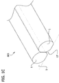
- Another embodiment of the invention is a three-dimensional structure including at least one filler body and a plurality of living cells which are cohered to one another.
- the cells form a tubular structure substantially surrounding the at least one filler body.
- the filler body includes a compliant biocompatible material that resists migration and ingrowth of cells into the material and which resists adherence of cells to the material.
- a mold may be used to produce a multicellular body comprising a plurality of living cells cohered to one another.
- the mold has biocompatible substrate that is resistant to migration and ingrowth of cells into the substrate and resistant to adherence of cells to the substrate.
- the substrate is shaped to receive a composition comprising plurality of cells having a relatively lower cohesion and hold the composition in a desired shape during a maturation period during which the cohesion increases to form the multicellular body.
- the desired shape of the multicellular body has a length of at least about 1000 microns and is configured so every cell within the multicellular body is no more than about 250 microns from an exterior of the body.
- a tool may be used for making a mold that is suitable for producing a plurality of multicellular bodies in which each body includes a plurality of living cells cohered to one another.
- the tool has a a body having a top and a bottom.
- a plurality of fins extend from the bottom of the body.
- Each of the fins has a width in the range of about 100 microns to about 800 microns for forming grooves in a biocompatible gel substrate configured for forming living cells placed in the grooves into elongate multicellular bodies.
- the fins have longitudinal axes and at least one of the fins is spaced laterally from the longitudinal axis of another of the fins.
- New structures and methods for producing engineered tissue are provided.
- the technology involves use of novel multicellular bodies as building blocks that can be used to assemble a three-dimensional construct that can become a desired engineered tissue through maturation.
- Each multicellular body comprises a plurality of living cells that are sufficiently cohered to one another to allow the body to be handled (e.g., picked up and moved) as a single object.
- the cohesion of the multicellular body is suitably sufficient to allow the body to support itself (e.g., on a work surface or in an assembly that includes multiple multicellular bodies) for a period of time sufficient to enable the living cells to cohere to the living cells of an adjoining multicellular body.
- the ability to pick up and move a plurality of living cells in the form of a self-supporting multicellular body provides flexibility to assemble numerous different three-dimensional constructs.
- the multicellular bodies can be used in conjunction with one or more filler bodies (e.g., bodies comprising a biocompatible material that resists migration and ingrowth of cells from the multicellular bodies into the filler bodies and resists adherence of cells to the filler bodies) to assemble constructs that can become a tubular engineered tissue through maturation.
- the multicellular bodies and filler bodies can also be used to assemble constructs that become engineered tissues having other shapes through maturation. Further, because the multicellular bodies are self supporting, there is no need to embed the multicellular bodies in a supporting gel or scaffold.
- the ability to "print in air” facilitates arranging the multicellular bodies in a manner that ensures the multicellular bodies are in direct contact with one another. Better contact between the multicellular bodies can facilitate efficient and reliable fusion of the multicellular bodies during maturation.
- the filler bodies can be easily removed from the exterior and interior (e.g. the lumen of a tubular structure) of a mature engineered tissue.
- some of the methods disclosed herein use elongate multicellular bodies as the building blocks for the engineered tissue. Because elongate multicelluar bodies are already cohered to one another over a significant length along a longitudinal axis of the body, fusion of the multicellular bodies is more reliable and can be achieved in less time. Further, elongate multicellular bodies can be arranged in side-by-side adjoining relation to establish contact between the multicellular bodies along a contact area having a substantial length. This can facilitate rapid and reliable fusion of the adjoining multicellular bodies to one another.
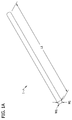
- a multicellular body also referred to herein as an intermediate cellular unit, generally designated 1, is illustrated in Fig. 1 .
- the multicellular body 1 includes a plurality of living cells that are cohered to one another.
- the multicellular body 1 comprises a plurality of cells cohered together in a desired three-dimensional (3-D) shape with viscoelastic consistency and sufficient integrity for easy manipulation and handling during a bio-engineering process, such as tissue or organ engineering.
- Sufficient integrity means that the multicellular body, during the subsequent handling, is capable of retaining its physical shape, which is not rigid, but has a viscoelastic consistency, and maintaining the vitality of the cells.
- the multicellular body 1 may be composed of any one or more pre-selected cell types.
- the choice of cell type will vary depending on the desired three-dimensional biological tissue.
- the cells used to form the multicellular bodies can advantageously comprise a cell type or cell types typically found in vascular tissue (e.g., endothelial cells, smooth muscle cells, fibroblasts, etc.).
- Other cell types may be used to form the multicellular body if it is to be used to engineer a different type of three-dimensional tissue (e.g., intestine, liver, kidney, etc.).
- Non-limiting examples of suitable cell types include contractile or muscle cells (e.g., striated muscle cells, including myoblasts and cardiomyocytes, and smooth muscle cells), neural cells, fibroblasts, connective tissue cells (including the cell types which make up bone and cartilage, cells capable of differentiating into bone forming cells and chondrocytes, and cell types which make up lymph tissues), parenchymal cells, epithelial cells (including endothelial cells that form linings in cavities and vessels or channels, exocrine and endocrine secretory epithelial cells, epithelial absorptive cells, keratinizing epithelial cells, and extracellular matrix secretion cells), hepatocytes, and undifferentiated cells (such as stem cells, and other precursor cells), among others.
- the cells used to form the multicellular body 1 can be obtained from
- the multicellular body 1 may be homocellular or heterocellular.
- the plurality of living cells includes a plurality of living cells of a single cell type. Almost all of the living cells in a homocellular multicellular body are cells of the single cell type, subject to some tolerance for low levels of impurities including a relatively small number of cells of a different cell type that have no more than a negligible impact on the maturation of a construct including the homocellular multicellular body.
- a heterocellular multicellular body includes significant numbers of cells of more than one cell type.
- a multicellular body can comprise a plurality of living cells of a first type and a plurality of living cells of a second type (etc.), the second cell type being different from the first cell type.
- the multicellular bodies are to be used to create vascular tissue, for instance, the cells of the first type can be endothelial cells and the cells of the second type can be smooth muscle cells, the cells of the first type can be endothelial cells and the cells of the second type can be fibroblasts, or the cells of the first type can be smooth muscle cells and the cells of the second type can be fibroblasts.
- Heterocellular multicellular bodies can also include a plurality of cells of a first cell type, a plurality of cells of a second cell type, and a plurality of cells of a third cell type with each of the first, second and third cell types being different from the others of the first, second, and third cells types.
- a multicellular body that is suitable for producing an engineered blood vessel can include endothelial cells, smooth muscle cells, and fibroblasts.
- the living cells in a heterocellular body may remain unsorted or can "sort out" (e.g., self-assemble) during the fusion process to form a particular internal structure for the engineered tissue.
- the self sorting of cells is consistent with the predictions of the Differential Adhesion Hypothesis (DAH).
- DASH Differential Adhesion Hypothesis
- the DAH explains the liquid-like behavior of cell populations in terms of tissue surface and interfacial tensions generated by adhesive and cohesive interactions between the component cells.
- cells can sort based on differences in the adhesive strengths of the cells. For example, cell types that sort to the center of a heterocellular multicellular body generally have a stronger adhesion strength (and thus higher surface tension) than cells that sort to the outside of the multicellular body.
- heterocellular multicellular bodies may comprise a sort of pre-built internal structure, based on the adhesive and cohesive properties of the component cells, and the environment in which the cells are located. This can be used to build more complex biological structures. For example, while building a simple contractile tube, homocellular multicellular bodies composed of muscle cells can be used; to build a blood vessel-like structure, at least two cell types can be used.
- a heterocellular multicellular body to be used for building an engineered blood vessel can suitably include (i) endothelial cells and smooth muscle cells; (ii) smooth muscle cells and fibroblasts; (iii) endothelial cells and fibroblasts; or (iv) endothelial cells, smooth muscle cells, and fibroblasts.
- endothelial cells and smooth muscle cells i.e., the lumen
- smooth muscle cells form a layer surrounding the endothelial cells
- the fibroblasts form an outer layer surrounding the smooth muscle layer.
- heterocellular multicellular bodies can include a plurality of living cells of a first cell type, a plurality of cells of a second type, and a plurality of cells of a third type. If such multicellular bodies are to be used to create vascular tissue, for instance, the cells of the first cell type can suitably be endothelial cells, the cells of the second cell type can suitably be smooth muscle cells, and the cells of the third cell type can suitably be fibroblasts. Again, self-sorting of the cells may occur in such heterocellular multicellular bodies.
- these cell types may sort such that the endothelial cells line the internal structure of the tube (i.e., the lumen), the smooth muscle cells form a layer substantially surrounding the endothelial cells, and the fibroblasts form the outer layer of the tubular structure, substantially surrounding both the layer of endothelial cells and the layer of smooth muscle cells.
- the multicellular body 1 suitably includes one or more extracellular matrix (ECM) components or one or more derivatives of one or more ECM components in addition to the plurality of cells.
- ECM extracellular matrix
- the multicellular bodies may contain various ECM proteins (e.g., gelatin, fibrinogen, fibrin, collagen, fibronectin, laminin, elastin, and/or proteoglycans).
- ECM components or derivatives of ECM components can be added to a cell paste used to form the multicellular body, as discussed in further detail below.
- the ECM components or derivatives of ECM components added to the cell paste can be purified from a human or animal source, or produced by recombinant methods known in the art.
- the ECM components or derivatives of ECM components can be naturally secreted by the cells in the multicellular body, or the cells used to make the multicellular body can be genetically manipulated by any suitable method known in the art to vary the expression level of one or more ECM components or derivatives of ECM components and/or one or more cell adhesion molecules or cell-substrate adhesion molecules (e.g., selectins, integrins, immunoglobulins, and cadherins).
- the ECM components or derivatives of ECM components may promote cohesion of the cells in the multicellular body.
- gelatin and/or fibrinogen can suitably be added to the cell paste which is used to form the multicellular body. The fibrinogen can then be converted to fibrin by the addition of thrombin.
- the multicellular body 1 in some instances suitably includes a tissue culture medium.
- the tissue culture medium can be any physiologically compatible medium and will typically be chosen according to the cell type(s) involved as is well known in the art.
- the tissue culture medium may comprise, for example, basic nutrients such as sugars and amino acids, growth factors, antibiotics (to minimize contamination), etc.
- the cohesion of the cells in the multicellular body 1 is suitably sufficiently strong to allow the multicellular body to retain a three-dimensional shape while supporting itself on a flat surface.
- the multicellular body 1 is supporting itself on a flat surface 13.
- the multicellular body is sufficiently cohesive to retain a height that is suitably at least one half its width, and more suitably about equal to the width.
- the multicellular body 1 is supported by a flat exterior surface 15 formed on the bottom of the multicellular body by contact between the multicellular body and the surface 13.
- the area A1 of the contact surface 15 may be larger than the initial contact area due to slight deformation of the multicellular body.
- the area A1 of the contact surface 15 is suitably smaller than the area A2 of a two dimensional projection of the multicellular body 1 onto the support surface 13 (See Fig. 1B ).
- a portion of the multicellular body 1 e.g., each of the sides as illustrated in Fig. 1B
- the multicellular body 1 is supported by the multicellular body 1 above the work surface 13.
- two or more of the multicellular bodies 1 are placed in side-by-side adjoining relation to one another on the flat surface 13 ( Fig. 1C ), their self-supporting abilities in combination with the three-dimensional shape in which they retain themselves can form a void space 17 under their sides and above the work surface.
- the cohesion of the cells in the multicellular body 1 is also suitably sufficiently strong to allow the multicellular body to support the weight of at least one similarly sized and shaped multicellular body or filler body when the multicellular body is assembled in a construct in which the multicellular bodies and filler bodies are stacked on top of one another (See Fig. 2 , discussed in more detail below).
- the cohesion of the cells in the multicellular body 1 is also suitably sufficiently strong to allow the multicellular body to be picked up by an implement (e.g., a capillary micropipette) (See Fig. 3D , discussed in more detail below).
- the multicellular body 1 can suitably be non-innervated (i.e., it is substantially free of neurons) or non-cartilaginous, or both non-innervated and non-cartilaginous.
- the multicellular body can be described as an "engineered" multicellular body because it is different from biological structures that arise without the guidance of human ingenuity. In other words, the multicellular body is synthetic, or non-naturally occurring.
- the multicellular body 1 can have various sizes and shapes within the scope of the invention.
- the multicellular body 1 illustrated in Fig. 1 is a lumenless body, meaning that there is no open passage extending through the multicellular body.
- the multicellular body 1 suitably has substantially no voids, hollow spaces or the like within the body. This is one difference between the multicellular body 1 illustrated in Fig. 1 and prior art engineered blood vessels and other prior art tubular engineered tissues.
- the multicellular body 1 illustrated in Fig. 1A-1B is configured to limit cell necrosis caused by inability of oxygen and/or nutrients to diffuse into central portions of the multicellular body.
- the multicellular body 1 is suitably configured so none of the living cells therein is more than about 250 microns from an exterior surface of the multicellular body, and more suitably so none of the living cells therein is more than about 200 microns from an exterior of the multicellular body. Because of the proximity of the cells in the central portions of the multicellular body 1 to the exterior surface of the multicellular body, cells in the multicellular body can be supplied with oxygen and/or nutrients by diffusion thereof from a void space at the exterior surface of the multicellular body toward the central portions of the body. Although there may be some necrosis of cells in one or more portions of the multicellular body (e.g., the central portion), the necrosis is limited.
- the multicellular body 1 in Fig. 1 is also an elongate body having a length L1 that is significantly larger than its height H1 and its width W1.
- the length L1 of the multicellular body 1 is suitably at least about 1000 microns (e.g., in the range of about 1000 microns to about 30 centimeters), more suitably at least about 1 centimeter (e.g., in the range of about 1 centimeter to about 30 centimeters), still more suitably at least about 5 centimeters (e.g., in the range of about 5 centimeters to about 30 centimeters).
- the height H1 and width W1 of the elongate multicellular body 1 illustrated in Fig. 1 are suitably significantly less than its length L1.
- the length L1 is suitably at least twice the width W1 and at least twice the height H1, meaning the body 1 has an aspect ratio (i.e., the ratio of the length to the longest dimension orthogonal to the length) that is at least about 2, more suitably at least about 10 and still more suitably at least 20.
- the aspect ratio can also be considerably higher than 20 within the scope of the invention; for example the aspect ratio can be 2000.
- the multicellular body 1 illustrated in Fig. 1 also has a relatively narrow width W1 and a relatively short height H1.
- the average cross-sectional area of the multicellular body 1 along its length L is suitably in the range of about 7,850 square microns to about 360,000 square microns, more suitably in the range of about 31,400 square microns to about 250,000 square microns, and still more suitably in the range of about 31,400 square microns to about 90,000 square microns.
- 1 (which is substantially cylindrical and has a circular cross section) suitably has an average diameter along its length in the range of about 100 microns to about 600 microns (corresponding to an average cross-sectional area in the range of about 7,850 square microns to about 282,600 square microns), more suitably in the range of about 200 microns to about 500 microns (corresponding to an average cross-sectional area in the range of about 31,400 square microns to about 196,250 square microns), and still more suitably in the range of about 200 microns to about 300 microns (corresponding to an average cross-sectional area in the range of about 31,400 square microns to about 70.650 square microns).
- the multicellular body 1 illustrated in Fig. 1 is substantially cylindrical and has a substantially circular cross section
- multicellular bodies having different sizes and shapes are within the scope of of the invention.
- the multicellular body can be an elongate shape (e.g., a cylindrical shape) with a square, rectangular, triangular, or other non-circular cross sectional shape within the scope of the invention.
- the multicellular body can have a generally spherical shape, a non-elongate cylindrical shape, or a cuboidal shape within the scope of the invention.
- a multicellular body can be fabricated from a cell paste containing a plurality of living cells or with a desired cell density and viscosity.
- the cell paste can be shaped into a desired shape and a multicellular body formed through maturation (e.g., incubation).
- an elongate multicellular body is produced by shaping a cell paste including a plurality of living cells into an elongate shape. The cell paste is incubated in a controlled environment to allow the cells to cohere to one another to form the elongate multicellular body.
- a multicellular body is produced by shaping a cell paste including a plurality of living cells in a device that holds the cell paste in a three-dimensional shape.
- the cell paste is incubated in a controlled environment while it is held in the three dimensional shape for a sufficient time to produce a body that has sufficient cohesion to support itself on a flat surface, as described above.
- the cell paste can suitably be provided by: (A) mixing the cells or cell aggregates (also referred to herein as "pre-selected” cells or cell aggregates) (may be one or more cell types) and a cell culture medium (also referred to herein as a "pre-selected” medium)(e.g., in a pre-determined ratio) to result in a cell suspension (also referred to herein as a cellular mixture), and (B) compacting the cellular mixture to produce the cell paste with a desired cell density and viscosity.
- the compacting may be achieved by a number of methods, such as by concentrating a particular cell suspension that resulted from cell culture to achieve the desired cell concentration (density), viscosity, and consistency required for the cell paste.
- a relatively dilute cell suspension from cell culture may be centrifuged for a determined time to achieve a cell concentration in the pellet that allows shaping in a mold.
- Tangential flow filtration is another suitable method of concentrating or compacting the cells.
- Compounds may also be combined with the cell suspension to lend the extrusion properties required.
- suitable compounds include collagen, hydrogels, Matrigel, nanofibers, self-assembling nanofibers, gelatin, fibrinogen, etc.
- the cell paste used in these methods is suitably produced by mixing a plurality of living cells with a tissue culture medium, and compacting the living cells (e.g., by centrifugation). If one or more ECM components, or one or more derivatives of one or more ECM components are to be included in the cell paste (as discussed in further detail below), the cell pellet can suitably be resuspended in one or more physiologically acceptable buffers containing the ECM component(s) or derivative(s) of ECM component(s) and the resulting cell suspension centrifuged again to form the cell paste.
- the cell density of the cell paste desired for further processing may vary with cell types.
- the interactions between cells determine the properties of the cell paste, and different cell types will have a different relationship between cell density and cell-cell interaction.
- the cells may be pre-treated to increase cellular interactions before shaping the cell paste. For example, cells may be incubated inside a centrifuge tube after centrifugation in order to enhance cell-cell interactions prior to shaping the cell paste.
- the cell paste can be manipulated, manually molded or pressed (e.g., after concentration/compaction) to achieve the desired shape.
- the cell paste may be taken up (e.g., aspirated) into a preformed instrument, such as a micropipette (e.g., a capillary pipette), that shapes the cell paste to conform to an interior surface of the instrument.
- a preformed instrument such as a micropipette (e.g., a capillary pipette)
- the cross sectional shape of the micropipette e.g., capillary pipette
- the cell paste may also be shaped by depositing it into a preformed mold, such as a plastic mold, metal mold, or a gel mold.
- centrifugal casting or continuous casting may be used to shape the cell paste.
- the shaping includes retaining the cell paste in a shaping device to allow the cells to partially cohere to one another in the shaping device.
- cell paste 55 can be aspirated into a shaping device 51 (e.g., a capillary pipette) and held in the shaping device for a maturation period (also referred to herein as an incubation period) ( Fig. 3B ) to allow the cells to at least partially cohere to one another.
- a shaping device 51 e.g., a capillary pipette
- a maturation period also referred to herein as an incubation period
- the multicellular body 1 can be produced in a process that has only a single maturation step (e.g, a single incubation step).
- the method suitably includes shaping the cell paste 55 in a single shaping device 51 and incubating the shaped cell paste in a single controlled environment to allow the cells to cohere to one another to form the multicellular body 1.
- the shaping device 51 e.g., capillary pipette
- the shaping device 51 can suitably be part of a printing head of a bioprinter or similar apparatus operable to automatically place the multicellular body in a three-dimensional construct, as will be described in more detail below
- ECM components or derivatives of ECM components, for example gelatin and/or fibrinogen in the cell paste may facilitate production of a multicellular body in a single maturation step because such components can promote the overall cohesivity of the multicellular body.
- a shaping device such as a capillary pipette, which provides the cells only limited access at best to oxygen and/or nutrients, before viability of the cells is impacted.
- the partially cohered cell paste 55 is suitably transferred from the shaping device (e.g., capillary pipette) to a second shaping device 301 (e.g., a mold) that allows nutrients and/or oxygen to be supplied to the cells while they are retained in the second shaping device for an additional maturation period.
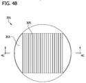
- a suitable shaping device 301 that allows the cells to be supplied with nutrients and oxygen is illustrated in Figs. 4A-4D .
- This shaping device is a mold 301 for producing a plurality of multicellular bodies (e.g., substantially identical multicellular bodies).
- the mold 301 includes a biocompatible substrate 303 made of a material that is resistant to migration and ingrowth of cells into the substrate and resistant to adherence of cells to the substrate.
- the mold 301 may be made of any material that will exclude the cells from growing or migrating into or adhering to the mold.
- the substrate 303 can suitably be made of Teflon® (PTFE), stainless steel, hyaluronic acid, agarose, agarose, polyethylene glycol, glass, metal, plastic, or gel materials (e.g., agarose gel or other hydrogel), and similar materials.
- the substrate 303 is shaped to receive a composition comprising plurality of cells having a relatively lower cohesion (e.g., from the first shaping device 51) and hold the composition in a desired three-dimensional shape during a maturation period during which the cohesion of the cells increases to form a multicellular body that has a greater cohesion relative to the composition before the maturation period, such as a multicellular body having any of the characteristics of the multicellular body 1 described above.
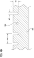
- the mold 301 is also suitably configured so tissue culture media can be supplied to the cell paste 55 (e.g., by dispensing tissue culture media onto the top of the mold). For example, as illustrated in Figs. 4A-4D a plurality of elongate grooves 305 are formed in the substrate 303.
- each groove 305 is suitably in the range of about 500 microns to about 1000 microns.
- the bottom of each groove 305 in the illustrated embodiment suitably has an arcuate (e.g., semicircular) cross-sectional shape for forming elongate cylindrical multicellular bodies that have a substantially circular cross-sectional shape.
- the width W5 of the grooves 305 is suitably slightly larger than the width of the multicellular body to be produced in the mold 301.
- the width W5 of the grooves is suitably in the range of about 300 microns to about 1000 microns.
- the spacing between the grooves 305 is not critical, but it will generally be desirable to space the grooves relatively close to one another to increase the number of multicellular bodies that can be produced in the mold 301.
- the strips of the substrate 303 between the grooves 305 each have a width W4 that is about 2 mm
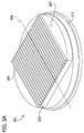
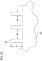
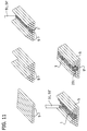
- Figs. 5A-5C illustrate one embodiment of a tool, generally designated 201, that can be used to make a mold that is suitable for making the multicellular bodies described above.
- a portion of the tool 201 is configured to be a negative of the portion of the mold 301 that retains the partially cohered cell paste during the second maturation period.
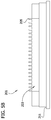
- the tool 201 suitably includes a body 203 and a plurality of projections 205 extending from the body.
- Each projection 205 is suitably sized and shaped to form a depression or receiving area in the mold substrate that will retain cell paste 55 in a shape such that none of the cells in the depression receiving area formed in the mold by the projection is more than about 300 microns from an exterior surface of the shaped cell paste.
- the particular tool 201 illustrated in Figs. 5A-5C is configured to produce the mold 301 illustrated in Figs. 4A-4B .
- the projections 205 are configured as a plurality of fins extending from a bottom 207 of the body 203. Each of the fins 205 is a negative of a one of the grooves 305 in the mold 301.
- the fins 205 have longitudinal axes 209 ( Fig. 5A ) and are configured to make a mold that can be used to make the elongate multicellular bodies 1 described above. At least one of the fins 205 is spaced laterally from the longitudinal axis 209 of another of the fins.
- each fin 205 suitably extends from the body 203 a distance D1 of about 1.5 mm.
- the distal end of the fins 205 have an arcuate (e.g., semicircular) cross-sectional shape corresponding to the shape of the bottom of the grooves 305 in the mold 301.
- each fin is suitably about 300 microns to about 1000 microns.
- the distance W2 separating the fins is suitably about 2mm.
- a lip 211 on the tool 201 is suitably configured to sit on the rim of a cell culture dish to hold the projections above the bottom of the dish.
- the tool 201 can be made of various materials from which the mold is easily separated, such as Teflon® (PTFE), stainless steel, and the like.
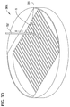
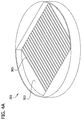
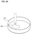
- a cell culture dish 221 is suitably filled with a liquid 223 that can be made to solidify or set up as a gel, as illustrated in Fig. 6A .
- the liquid can be an agarose solution 223.
- the tool 201 is placed on top of the cell culture dish 221 ( Fig. 6B ) so the lip 211 sits on the rim 225 of the cell culture dish and the projections 205 (e.g., fins) extend from the bottom 207 of the tool 201 into the liquid 223.
- the liquid 223 is allowed to set up to form a solid or gel substrate surrounding the distal ends of the projections 205 (e.g., fins).
- tool 201 is lifted off the cell culture dish to separate the tool 201 from the newly produced mold 301 ( Fig. 6C ).
- the partially cohered cell paste 55 is suitably transferred from the first shaping device 51 (e.g., a capillary pipette) to the second shaping device (e.g., the mold 301 illustrated in Figs. 4A-4D ).
- the partially cohered cell paste 55 can be transferred by the first shaping device 51 (e.g., the capillary pipette) into the grooves 305 of the mold 301, as illustrated in Fig. 3C .
- the method includes transferring the partially cohered cell paste 55 to a second shaping device 301, and retaining the partially cohered cell paste in the second shaping device to form the multicellular body 1.
- the cohesion of the cells will be sufficiently strong to allow the resulting multicellular body 1 to be picked up with an implement 51', e.g., a capillary pipette as illustrated in Fig. 3D .
- the capillary pipette 51' (now containing the mature multicellular body 1 that has been picked up out of a groove 305 in the mold 301) can suitably be part of a printing head of a bioprinter or similar apparatus operable to automatically place the multicellular body into a three-dimensional construct, as will be described in more detail below.
- the shaping includes retaining the cell paste 55 in a first shaping device 51 to allow the cells to partially cohere to one another in the first shaping device, transferring the partially cohered cell paste to a second shaping device 301, and retaining the partially cohered cell paste in the second shaping device to form the multicellular body 1.
- the cells may sufficiently cohere to form the multicellular body in the first shaping device 51, and the step of transferring the cell paste 55 to a second shaping device 301 and retaining the cell paste in the second shaping device may be unnecessary.
- the first shaping device 51 can suitably include a capillary pipette and the second shaping device can include a device that allows nutrients and oxygen to be supplied to the cells wile they are retained in the second shaping device, such as the above-described mold 301.
- the cross-sectional shape and size of the multicellular bodies will substantially correspond to the cross-sectional shapes and sizes of the first shaping device and optionally the second shaping device used to make the multicellular bodies, and the skilled artisan will be able to select suitable shaping devices having suitable cross-sectional shapes, cross-sectional areas, diameters, and lengths suitable for creating multicellular bodies having the cross-sectional shapes, cross-sectional areas, diameters, and lengths discussed above.
- cell types may be used to create the multicellular bodies of the present invention.
- one or more types of cells or cell aggregates both human and animal somatic cells, including, for example, all of the cell types listed above, may be employed as the starting materials to create the cell paste.
- cells such as smooth muscle cells, endothelial cells, chondrocytes, mesenchymal stem cells, myoblasts, fibroblasts, cardiomyocytes, Schwann cells, hepatocytes or Chinese hamster ovary (“CHO”) cells may be employed.
- a sample of cells from an intended recipient obtained, for example, by biopsy or cells from one or more established cell lines can be cultured to produce a sufficient quantity of cells for fabrication of the multicellular bodies.
- Multicellular bodies made from cells from an intended recipient are advantageous for avoiding host inflammatory responses or other acute or chronic rejection of the transplanted organ or tissue by the recipient.
- the multicellular body can be homocellular or heterocellular.
- the cell paste suitably is homocellular, i.e., it includes a plurality of living cells of a single cell type. Almost all of the living cells in cell paste to be used for creating a homocellular multicellular body will be cells of the single cell type, subject to some tolerance for low levels of impurities, including a relatively small number of cells of a different cell type that have no more than a negligible impact on the maturation of a construct which includes homocellular multicellular bodies made from such cell paste.
- cell paste for making homocellular multicellular bodies suitably includes cells of a first type, where at least about 90 percent of the cells in the cell paste are cells of the first cell type.
- the cell paste will suitably include significant numbers of cells of more than one cell type (i.e., the cell paste will be heterocellular).
- the cell paste can comprise a plurality of living cells of a first type and a plurality of living cells of a second type, the second cell type being different from the first cell type.
- the cell paste can comprise a plurality of living cells of a first cell type, a plurality of living cells of a second cell type, and a plurality of living cells of a third cell type.
- the plurality of living cells in the cell paste can suitably include: (i) endothelial cells and smooth muscle cells; (ii) smooth muscle cells and fibroblasts; (iii) endothelial cells and fibroblasts; or (iv) endothelial cells, smooth muscle cells, and fibroblasts.
- the living cells may "sort out” during the maturation and cohesion process based on differences in the adhesive strengths of the cells, and may recover their physiological conformation.
- one or more ECM components or one or more derivatives of one or more ECM components can suitably be included in the cell paste to incorporate these substances into the multicellular bodies, as noted above.
- the ECM components or derivatives of ECM components added to the cell paste can be purified from a human or animal source, or produced by recombinant methods known in the art. Adding ECM components or derivatives of ECM components to the cell paste may promote cohesion of the cells in the multicellular body. For example, gelatin and/or fibrinogen can be added to the cell paste.
- a solution of 10-30% gelatin and a solution of 10-80 mg/ml fibrinogen can be mixed with a plurality of living cells to form a cell suspension containing gelatin and fibrinogen.
- the cell suspension can then be compacted (e.g., by centrifugation) to form the cell paste.
- the cell paste formed by this process can then be shaped and incubated in a controlled environment to allow the cells to cohere to one another to form the multicellular body.
- the fibrinogen can be converted to fibrin by the addition of thrombin (e.g., during the printing process).
- the shaping step suitably comprises retaining the cell paste in a single shaping device to form the multicellular body
- the incubating step suitably comprises incubating the shaped cell paste in a single controlled environment to allow the cells to cohere to one another to form the multicellular body.
- the fabrication method generally comprises the steps of 1) providing a cell paste containing a plurality of pre-selected cells or cell aggregates (e.g., with a desired cell density and viscosity), 2) shaping the cell paste (e.g., into a desired shape), and 3) forming the multicellular body through maturation.
- the aforesaid forming step may be achieved through one or multiple steps to ensure the coherence of the multicellular body (e.g., cellular unit).
- the cell paste upon the initial maturation, may be partially stabilized, or partially hardened to form the multicellular body with integrity sufficient to allow further handling.
- the forming step may include two substeps: A) retaining the cell paste in the shaping device, such as a micropipette (e.g., a capillary pipette), for a first time period (e.g., a pre-determined time period) for the initial maturation, and B) depositing the shaped cell paste into a holding device, such as a mold, for a second time period (e.g., a pre-determined time period) for further maturation.
- the holding device is made of a material capable of excluding cells from growing or migrating into, or adherence onto it.
- the initial maturation will provide the cell paste with sufficient stability to remain intact during the handling in the further maturation process.
- the cell paste may be incubated at about 37°C for a time period (which may be cell-type dependent) to foster coherence.
- the cell paste may be held in the presence of cell culture medium containing factors and or ions to foster adherence.
- the cell paste may then be further incubated and cultured with medium in the further maturation process, which encourages retention of the desired shape.
- a micropipette e.g., a capillary pipette
- the present invention includes filler bodies which can be used in combination with the above-described multicellular bodies to form desired three-dimensional biological engineered tissues.
- the present invention includes a filler body (also referred to herein as a "filler matrix unit") to be used in combination with the multicellular bodies as building units for constructing a biological construct, where the filler bodies are used to define the domains of the desired 3-D bio-constructs that are devoid of multicellular bodies.
- the filler body is suitably a body having a pre-determined shape made of a material capable of excluding cells growing or migrating into or adhering to it.
- the filler body material is suitably permeable to nutrient media (also referred to herein as tissue culture medium or cell culture medium).
- the filler body material is suitably a biocompatible gel material selected from the group consisting of agarose, hyaluronic acid, polyethylene glycol, and agar, or other hydrogel or a non-gel flexible biocompatible material.
- the filler bodies can suitably be formed from different materials or from different concentrations of the same material.
- a lumen-forming filler body can be made of 4% agarose.
- the remaining filler bodies used to construct a desired three-dimensional biological engineered tissue can be made of 2% agarose.
- the filler body may assume any shape or size in accordance with the shape or size of the corresponding multicellular body, with a cylindrical shape as preferred.
- the filler bodies have shapes and sizes substantially identical to the shapes and sizes of the multicellular bodies with which they are to be used to build a desired three-dimensional biological engineered tissue.
- the filler bodies can suitably have any of the shapes described above in connection with the multicellular body 1.
- both the filler bodies and the multicellular bodies may be substantially cylindrical and have substantially circular cross-sections having substantially identical diameters (as shown in Fig. 2 ).
- the filler bodies and the multicellular bodies can have different sizes and or/shapes, so long as the filler bodies and multicellular bodies can be arranged according to a pattern such that a desired three-dimensional biological engineered tissue is formed when the multicellular bodies fuse to one another.
- the filler bodies can be substantially cylindrical and the multicellular bodies can be substantially spherical (as illustrated in Figure 2 ).
- the filler bodies and the multicellular bodies may both be elongate and substantially cylindrical, but have different lengths.
- the skilled artisan will recognize that there are many ways in which filler bodies and multicellular bodies of varying sizes and shapes can be combined to form a desired three-dimensional biological engineered tissue.
- a filler body is suitably produced by shaping a suitable gel-like material into a pre-determined shape.
- the method may further include the steps of: 1) decreasing (lowering) the viscosity of a filler material (i.e., the pre-selected filler material) to a liquid-like material, 2) shaping the liquid-like material (e.g., into a pre-selected shape), and 3) increasing (raising) the viscosity of the material to solidify into a filler body (e.g., with the pre-selected shape).
- a number of known methods may be used to decrease the viscosity of a filler material, including direct or indirect heating of the material, application of pressure, or changing its concentration.
- a number of methods may be employed in the shaping step, such as depositing the material into a precast mold, or drawing it into a chamber of desired shape by a pipette or negative displacement of a piston.
- a number of known methods may be employed to increase the viscosity of the material to solidify its shape, including direct or indirect cooling of the material, causing or allowing a solvent to be removed or evaporated, allowing chemical action to harden the material, changing the concentration of the components or allowing crosslinking of a polymeric material by chemical or other action.
- agarose solution (agarose originally in powder phase mixed with buffer and water) may be heated to reduce its viscosity and taken up (e.g., aspirated) into a capillary pipette (i.e., micropipette) with a desired dimension (or into a chamber of a desired shape by negative displacement of a piston).
- a capillary pipette i.e., micropipette
- capillary pipettes having various cross-sectional shapes can be used.
- a capillary pipette having a substantially circular cross-sectional shape along its length can be used to make filler bodies which are substantially cylindrical and which have substantially circular cross sectional shapes.
- a capillary pipette having a substantially square cross-section along its length can be used to make filler bodies which are substantially cylindrical and which have square cross-sectional shapes.
- filler bodies having a myriad of cross-sectional shapes can be produced in a similar manner using capillary pipettes as used in making multicellular bodies as described above.
- the agarose solution in the pipette may be cooled to room temperature, for example by forced air on the exterior of the pipette or plunging the pipette into a container with cold liquid, so that it can solidify into an agarose gel with the desired shape, i.e., filler body.
- the resulting filler body may be extruded from the pipette or chamber during the construction of a particular bio-construct.
- a filler body can suitably be produced by a bioprinter or similar apparatus as it assembles a three-dimensional construct comprising an arrangement of multicellular bodies and filler bodies.
- a capillary pipette can be part of a printing head of a bioprinter.
- the capillary pipette can be transported to a source of liquid that can set up as a gel.
- the capillary pipette can be transported to supply of agarose solution that is heated to maintain it in a liquid state.
- the liquid can be aspirated into the capillary pipette to shape the liquid into the shape of the filler body.
- the capillary pipette can be chilled (e.g., by immersing it in a cold water bath) in order to expedite the setting up of the agarose gel.
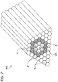
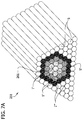
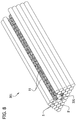
- the multicellular bodies and filler bodies described above can be used to produce a three-dimensional biological engineered tissue. Briefly, a plurality of multicellular bodies and a plurality of filler bodies are arranged according to a pattern such that each multicellular body contacts at least one of (i) another multicellular body, or (ii) a filler body. The multicellular bodies are then allowed to fuse with at least one other multicellular body to form a there-dimensional biological engineered tissue. The filler bodies can then be separated from the fused multicellular bodies to obtain the engineered tissue.
- the structure 101 includes a plurality of elongate multicellular bodies 1, each of which is suitably identical to the elongate multicellular body 1 described above.
- each of the elongate multicellular bodies 1 has suitably been produced according to the methods described above for producing a self-supporting multicellular tissue body that can be printed in air.
- the multicellular bodies 1 are arranged in a pattern in which each multicellular body contacts at least one other multicellular body. As best understood in reference to Fig. 1C , at least one of the multicellular bodies 1 contacts another of the multicellular bodies along a contact area that has a substantial length.
- FIG. 1C shows two multicellular bodies 1 in side-by-side adjoining relation on a surface 13 rather than arranged in the pattern illustrated in Fig. 2 , it is understood that the contact area between two of the multicellular bodies 1, can be substantially similar to the contact area illustrated in Fig. 1C whenever they are arranged in a pattern in which they are in side-by-side adjoining relation to one another.
- each of the multicellular bodies 1 contacts at least one (e.g., two) other multicellular bodies over a contact area having a substantial length.
- the contact area between adjoining elongate multicellular bodies in side-by-side relation suitably has a length of at least about 1000 microns, more suitably at least about 1 centimeter, more suitably at least about 5 centimeters, and still more suitably in the range of about 5 centimeters to about 30 centimeters.
- the contact area has a length that is suitably in the range of about 1000 microns to about 30 centimeters, and more suitably in the range of about 1 centimeter to about 30 centimeters.
- the length of the contact area can correspond to the length of the multicellular bodies 1.
- the contact area can have a length in excess of 30 centimeters (or any arbitrary length different from 30 centimeters) within the scope of the invention provided a person is willing to overcome practical difficulties, such as the need to obtain a sufficient quantity of cell paste, associated with production of long multicellular bodies.
- the multicellular bodies 1 are in contact with one another in Fig. 2 , at this initial stage of maturation the multicellular bodies are not cohered to one another.
- the structure also includes one or more filler bodies 5, each of which is suitably identical to the filler body described above.
- the structure in Fig. 2 includes a plurality of discrete filler bodies 5.
- the filler bodies 5 are arranged in the pattern with the multicellular bodies so each filler body contacts at least one multicellular body or another filler body.
- the multicellular bodies 1 and filler bodies 5 in Fig. 2 are arranged to form a plurality of spaces 17 in the structure 101 that are not occupied by the multicellular bodies and also not occupied by the filler bodies.
- the spaces 17 suitably contain tissue culture medium, which can be added to the structure 101 by pouring the tissue culture medium over the top of the multicellular bodies 1 and filler bodies 5.
- the spaces 17 can facilitate supply of nutrients and/or oxygen to the cells in the multicellular bodies 1 (e.g., during maturation).
- the multicellular bodies 1 in the structure illustrated in Fig. 2 can be homocellular bodies, heterocellular bodies, or a combination thereof.
- the multicellular bodies 1 can suitably include any of the cell types and combinations of cell types described above.
- the multicellular bodies are suitably substantially identical with respect to the cell types contained therein.
- one or more of the multicellular bodies contains cells of a different cell type than the other multicellular bodies in the structure within the scope of the invention.
- a majority of the cells in each of one or more of the multicellular bodies 1 can suitably be cells of a first cell type (e.g., endothelial cells or smooth muscle cells) and a majority of the cells in each of one or more other multicellular bodies in the structure 101 can be cells of a second cell type (e.g., smooth muscle cells or fibroblasts) that is different from the first cell type.
- the multicellular bodies 1 are suitably substantially uniform in shape.
- the filler bodies are also suitably substantially uniform in shape. Further, as illustrated in Fig. 2 , the multicellular bodies 1 have a shape that is substantially identical to the shape of the filler bodies 5.
- At least some of the multicellular bodies 1 are arranged to form a tube-like structure 31. At least one of the filler bodies 5' is inside the tube-like structure 31 and substantially surrounded by the multicellular bodies 1 that form the tube-like structure.
- the multicellular bodies 1 in Fig. 2 are arranged in a hexagaonal configuration to form a tube-like structure 31 surrounding one of the filler bodies 5.
- Each of the multicellular bodies 1 in the hexagonal configuration of Fig. 2 is in side-by-side adjoining relation with at least two neighboring elongate multicellular bodies.
- the one or more filler bodies 5' inside the tube-like structure 31 are lumen-forming filler bodies.
- the one or more lumen-forming filler bodies 5' are referred to as such because they prevent migration and ingrowth of cells from the multicellular bodies 1 into an elongate space that extends through the tube-like structure 31, which becomes a lumen after maturation of the structure according to the methods described below.
- the one or more lumen-forming filler bodies 5' do not develop any lumen within themselves during maturation.
- any arrangement of multicellular bodies that can via maturation produce a tubular engineered tissue that includes a plurality of living cells can be considered a tube-like structure whether or not there are filler bodies inside the tube-like structure.
- the tube-like structure can differ from a tubular structure by virtue of the fact the adjoining multicellular bodies are not cohered to one another at this stage of maturation so an object could be pushed into the space between two of the adjoining multicellular bodies forming the tube-like structure.
- FIG. 7 Another embodiment of a three-dimensional structure, generally designated 201, is illustrated in Fig. 7 . Except as noted, this structure can be substantially identical to the structure illustrated in Fig. 2 and described above.
- the structure 201 in Fig. 7 includes a plurality of multicellular bodies, each of which can be identical to the multicellular body 1 described above. However, in this structure 201 there are two different sets of multicellular bodies 1', 1" arranged in the pattern that forms the structure.
- a majority of the cells in the multicellular bodies 1' of the first set are cells of a first cell type and a majority of the cells in the multicellular bodies 1" of the second set (e.g., at least about 90 percent of the cells) are cells of a second cell type that is different from the first cell type.
- the majority of the cells in the first set of multicellular bodies 1' can suitably be endothelial cells and the majority of the cells in the second set of multicellular bodies 1" can suitably be smooth muscle cells.
- the majority of the cells in the first set of multicellular bodies 1' can suitably be endothelial cells and the majority of the cells in the multicellular bodies 1" in the second set can be fibroblasts.
- the majority of cells in the first set of multicellular bodies 1' can suitably be smooth muscle cells and the majority of the cells in the multicellular bodies 1" in the second set can be fibroblasts. It is also possible to use other cell types.
- the first set of multicellular bodies 1' is arranged in a hexagonal configuration (similar to the hexagonal configuration described above) surrounding one or more lumen-forming filler bodies 5'.
- the second set of multicellular bodies 1" is arranged in a larger hexagonal configuration surrounding the first set of multicellular bodies 1' and the one or more lumen-forming filler bodies 5'. Together, the multicellular bodies 1', 1" form a tube-like structure 231 that includes two different types of cells.
- the first set of multicellular bodies 1' are arranged to form an inner layer of the tube-like structure 231 and the second set of multicellular bodies 1" are arranged for form an outer layer of the tube-like structure.
- cells of the first cell type are more concentrated in an inner portion of the tube-like structure 231 and cells of the second cell type (e.g., smooth muscle cells) are more concentrated in an outer portion of the tube-like structure, such that a ratio of the number of endothelial cells to the number of non-endothelial cells in the first set of multicellular bodies 1' is greater than a ratio of the number of endothelial cells to the number of non-endothelial cells in the second set of multicellular bodies 1", or a ratio of the number of smooth muscle cells to the number cells that are not smooth muscle cells in the second set of multicellular bodies 1" is greater than a ratio of the number of smooth muscle to the number of cells that are not smooth muscle cells in the first set of multicellular bodies 1'.
- a ratio of the number of endothelial cells to the number of non-endothelial cells in the first set of multicellular bodies 1' is greater than a ratio of the number of endothelial cells to the number of non-endot
- This arrangement can facilitate production of a tubular engineered tissue having an inner layer of cells of the first type and an outer layer of cells of the second type.
- the structure 201 can be used to produce an engineered blood vessel having an inner layer of endothelial cells and an outer layer of smooth muscle cells.
- a first set of multicellular bodies 1' each comprising a plurality of endothelial cells and a plurality of smooth muscle cells are arranged to form an inner layer of the tube-like structure 231 and a second set of multicellular bodies 1" comprising fibroblasts are arranged for form an outer layer of the tube-like structure.
- endothelial cells are more concentrated in an inner portion of the tube-like structure 231
- smooth muscle cells are more concentrated in a center portion of the tube-like structure
- fibroblasts are more concentrated in an outer portion of the tube-like structure, such that a ratio of the number of fibroblasts to the number of non-fibroblasts in the second set of multicellular bodies 1" is greater than a ratio of the number of fibroblasts to the number of non-fibroblasts in the first set of multicellular bodies 1'.
- a first set of multicellular bodies 1' each comprising endothelial cells are arranged to form an inner layer of the tube-like structure 231 and a second set of multicellular bodies 1" each comprising and a plurality of smooth muscle cells and a plurality of fibroblasts are arranged for form an outer layer of the tube-like structure.
- endothelial cells are more concentrated in an inner portion of the tube-like structure 231
- smooth muscle cells are more concentrated in a center portion of the tube-like structure
- fibroblasts are more concentrated in an outer portion of the tube-like structure, such that a ratio of the number of endothelial cells to the number of non-endothelial cells in the first set of multicellular bodies 1' is greater than a ratio of the number of endothelial cells to the number of non-endothelial cells in the second set of multicellular bodies 1 ".
- Fig. 7A illustrates another example of a three-dimensional structure 251 of the present invention.
- This structure 251 is substantially the same as the structure illustrated in Fig. 7 except that it also includes a third set of multicellular bodies 1"'.
- a majority of the cells in the multicellular bodies 1'" in the third set are of a cell type that is different from each of the cell types constituting the majority cell type for the respective multicellular bodies 1', 1" in the first and second sets.
- the multicellular bodies 1"' in the third set are suitably arranged in a generally hexagonal configuration surrounding and adjoining the multicellular bodies 1" in the second set.
- the multicellular bodies 1"' in the third set suitably surround the multicellular bodies 1" in the second set and the multicellular bodies 1' in the first set.
- the multicellular bodies 1', 1", 1"' suitably form a tube-like structure 261 formed by three layers of multicellular bodies.
- One or more lumen-forming filler bodies 5' extends axially through the tube-like structure 261.
- the majority of the cells in the multicellular bodies 1' in the first set are suitably endothelial cells
- the majority of the cells in the multicellular bodies 1" in the second set are suitably smooth muscle cells
- the majority of the cells in the multicellular bodies 1'" in the third set are suitably fibroblasts, such that a ratio of the number of fibroblasts to the number of non-fibroblasts in the third set of multicellular bodies 1"' is greater than a ratio of the number of fibroblasts to the number of non-fibroblasts in the first set of multicellular bodies 1' or the second set multicellular bodies 1".
- the multicellular bodies 1', 1", 1"' can have other majority cell types within the scope of the invention.
- FIG. 8 Another embodiment of a three-dimensional structure 301 of the present invention is illustrated in Fig. 8 . Except as noted, this structure 301 is substantially identical to the structure 101 described above and illustrated in Fig. 2 .
- each of the elongate cylindrical multicellular bodies 1 used in the structure 101 illustrated in Fig. 2 has been replaced with a series of substantially spherical multicellular bodies 11.
- the spherical multicellular bodies 11 are suitably produced according to the methods described above for producing a self-supporting multicellular body.
- the shape of the spherical multicellular bodies 11 is different from the multicellular body 1 described above because they do not have any of its elongate characteristics.
- the spherical multicellular bodies 11 are suitably arranged to form a tube-like structure 331 surrounding one or more lumen-forming filler bodies 5'.
- each series (e.g., line) of multicellular bodies can be offset from neighboring series of multicellular bodies so the center of each spherical multicellular body is axially aligned with a point about half the distance between the centers of the adjacent spherical bodies in the neighboring series. This can facilitate fusion because it results in increased contact area between neighboring spherical multicellular bodies 11.
- the multicellular bodies 1', 1", and 1 "' in Figs. 7 or 7A can be also be replaced with spherical multicellular bodies 11.
- the spherical multicellular bodies provide the same options with respect to cell type, combinations of cell types in different multicellular bodies, and mixtures of cell types within the multicellular bodies as the elongate multicellular bodies.
- this structure is substantially identical to the structure 101 described above and illustrated in Fig. 2 .
- each of the elongate cylindrical filler bodies used in the structure 101 illustrated in Fig. 2 has been replaced with a series of substantially spherical filler bodies.
- the spherical filler bodies are suitably produced according to the methods described above for producing a self-supporting filler body.
- the shape of the spherical filler bodies is different from the filler body described above because they do not have any of its elongate characteristics.
- each series (e.g., line) of filler bodies can be offset from neighboring series of filler bodies so the center of each spherical filler body is axially aligned with a point about half the distance between the centers of the adjacent spherical bodies in the neighboring series. This can facilitate stacking because it results in increased contact area between neighboring spherical filler bodies.
- the spherical filler bodies provide the same options with respect to materials (e.g., agarose, etc.) as the elongate filler bodies.
- the structure is substantially identical to the structure shown in Fig. 8 except that the structure also includes the spherical filler bodies as described above to replace at least some of the elongate filler bodies as shown in Fig. 8 .
- Figure 9 illustrates a portion of another embodiment of a three-dimensional structure, generally designated 401.
- This structure is suitably an arrangement of elongate multicellular bodies 1, which can be substantially identical to the multicellular body 1 described above and a plurality of filler bodies 5.
- Fig. 9 some of the multicellular bodies 1 and filler bodies 5 have been removed to show the internal arrangement of the multicellular bodies and filler bodies.
- one or more of the filler bodies 5 are arranged to be lumen-forming filler bodies 5'.
- the lumen-forming filler bodies 5' are arranged to prevent ingrowth of cells from the multicelluar bodies into first and second elongate spaces 411, 413.
- the lumen-forming filler bodies 5' are substantially surrounded by the multicellular bodies 1.
- the multicellular bodies are suitably arranged to form a first tube-like structure 431' surrounding the first elongate space 411 and a second tube-like structure 431" surrounding the second elongate space 413.
- the tube-like structures 431', 431" are not shown in their entirety, they are similar to the tube-like structure 31 in Fig. 2 except as noted.
- One of the tube-like structures 431" has a larger diameter than the other tube-like structure 431'. At least some of the elongate multicellular bodies 1 that form the smaller diameter tube-like structure 431' contact at least some of the elongate multicellular bodies 1 that form the larger diameter tube-like structure at an intersection 441 of the tube-like structures 431', 431". Further, at least one lumen-forming filler body 5' suitably extends through a gap 451 in the multicellular bodies 1 to connect an end of the first elongate space to the second elongate space so the lumens formed in the tube-like structure 431', 431" by the lumen-forming bodies 5' are connected to one another.
- a branched tubular engineered tissue such as an engineered blood vessel.
- the example, illustrated in Fig. 9 produces a single branch, but the technique can be expanded to produce higher order branching structures, including structures having braches that have multiple different diameters.
- the elongate multicellular bodies 1 in Fig. 9 can be replaced with spherical multicellular bodies 11, as illustrated by the structure 501 in Fig. 10 .
- the tube-like structures 431', 431" formed by the elongate multicellular bodies 1 ( Fig. 9 ) or the spherical multicellular bodies ( Fig. 10 ) can suitably be modified to include one or more additional sets of multicellular bodies in a manner similar to what is illustrated in Figs. 7 and 7A .
- the same options with respect to cell type, combinations of cell types in different multicellular bodies, and mixtures of cell types within the multicellular bodies that have been described above also apply to the structures 401, 501 illustrated in Figs. 9 and 10 .
- Figure 1C illustrates another three-dimensional structure 601.
- This structure 601 does not necessarily include any filler bodies. Instead a series of elongate multicellular bodies are arranged in side-by-side adjoining relation to form a sheet-like structure. Although there are only two multicellular bodies 1 in the sheet structure 601 illustrated in Fig. 1C , any number of additional multicellular bodies can be placed alongside these multicellular bodies so each multicellular body is in contact with at least one other multicellular body to increase the width of the sheet structure.
- one method generally involves arranging a plurality of elongate multicellular bodies 1 according to a pattern such that each of the multicellular bodies contacts at least one other multicellular body and then allowing at least one (e.g., all) of the multicellular bodies to fuse to at least one other multicellular body to produce a desired three-dimensional biological engineered tissue. It is not necessary to include any filler bodies in the arrangement of multicellular bodies (see e.g., Fig. 1C ).
- each of the multicellular bodies contacts at least one other multicellular body or a filler body and then allow the multicellular bodies to fuse to form a desired three-dimensional biological engineered tissue.
- a number of methods may be used to deliver the multicellular bodies in a pre-determined pattern to produce the desired three-dimensional structure.
- the multicellular bodies can be manually placed in contact with one another or a filler body, deposited in place by extrusion from a pipette, nozzle, or needle, or positioned in contact by an automated machine.
- one or more implements which can suitably include the first shaping device 5 describe above, the capillary pipette 51' that takes the multicellular body out of the mold 301, as described above, and or a different implement
- pick up a multicellular body e.g. to take them out of the mold 301 described above).
- the implement transports the multicellular body to an assembly area (for example, a glass surface) where a three-dimensional construct (e.g., as illustrated in any of Figs. 1C, 2, 7, 7A, or 8-10 ) is being assembled and dispenses or otherwise places the multicellular body in position relative to any other multicellular bodies and any filler bodies that have already been transported to the assembly area and placed in the construct that is being assembled.
- a three-dimensional construct e.g., as illustrated in any of Figs. 1C, 2, 7, 7A, or 8-10
- the process is suitably repeated to add another multicellular body or a filler body to the construct (e.g., by placing it alongside a multicellular body that has already been placed in the construct).
- another implement which is not shown, but which may be similar to the shaping device 51 or capillary pipette 51'
- transport the filler body to the assembly area and dispense or otherwise place the filler body in its position within the construct that is being assembled whenever a filler body is needed.
- the implement 51, 51' used to transport multicellular bodies to the assembly area is suitably carried by a printing head of a bioprinter or other automated apparatus operable to arrange the multicellular bodies and filler bodies in a desired pattern.
- a bioprinter for example, one suitable bioprinter is disclosed in U.S. Patent App. No. 20040253365 ,
- biopfinters and similar apparatus that can be used to arrange the multicellular bodies (and filler bodies if they are used) into a suitable construct.
- the implement used to transport filler bodies to the assembly area is suitably part of another head of the bioprinter.
- a bioprinter can have multiple heads and/or the various implements 51, 51' for transporting the multicellular bodies and filler bodies can be loaded sequentially into one or more bioprinter heads.
- the methods described herein can be performed manually (e.g., using one or more capillary pipettes).
- the multicellular bodies I are suitably placed (e.g., stacked) on top of one or more filler bodies 5.
- the multicellular bodies 1 are suitably placed adjacent the other multicellular bodies and or filler bodies 5.
- the multicellular bodies 1 are not pushed into or embedded in any of the filler bodies 5. This can be referred to as "printing in air” because the multicellular bodies are not dispensed into a gel or liquid.
- the method illustrated in Fig. 12 is substantially similar to the one illustrated in Fig. 11 except that the spherical multicellular bodies 11 are used instead of the elongate multicellular bodies I illustrated in Fig. 11.
- Figure 11 and 12 illustrate the process of making the constructs shown in Figs. 2 and 8 , respectively, but it is understood that constructs such as those illustrated in Figs. 1C , 7 , 7A , 8 , and 9 and described above (and many others) can be produced in substantially the same way within the scope of the invention.
- tissue culture medium is suitably poured over the top of the construct.
- the tissue culture medium can enter the spaces 17 between the multicellular bodies and the filler bodies to support the cells in the multicellular bodies.
- the multicellular bodies in the three-dimensional construct are allowed to fuse to one another to produce a biological engineered tissue.
- fuse it is meant that the cells of contiguous multicellular bodies become adhered to one another, either directly through interactions between cell surface proteins, or indirectly through interactions of the cells with ECM components or derivatives of ECM components. After fusion, any filler bodies that were included in the construct are separated from the engineered tissue.
- any filler bodies outside of the tube can be removed (e.g., by peeling them away from the tubular structure formed from the tube-like construct).
- Any of the lumen-forming filler bodies 5' inside the tubular structure are suitably pulled out of an open end of the tubular structure.
- the lumen-forming filler bodies 5' can suitably be made of a flexible material if desired to facilitate pulling the filler bodies out of the lumen, which may be helpful (e.g., if the engineered tissue is a branched tubular structure).
- Another option is to make the filler bodies 5 and any lumen-forming filler bodies 5' from a material that can be dissolved (e.g., by temperature change , light, or other stimuli) after fusion.
- Also disclosed herein is another method of engineering a biological construct with a 3-D shape, such as a tissue, blood vessel, or an organ, using the multicellular bodies by further delivering a plurality of multicellular bodies according to a pre-determined 3-D pattern in a pre-selected receiving environment, so that the cellular units may fuse into the desired bio-cunatruct.
- the two or more multicellular bodies that are fused may be of identical or differing shapes and sizes, and may contain the same or differing cell types.
- the multicellular bodies may be applied in bio-construct-engineering in number of ways. For example, two differently shaped multicellular bodies comprising a top half and a bottom half of a desired structure may be produced, and may be brought into contact and allowed to fuse.
- a plurality of multicellular bodies may be assembled and allowed to fuse into a desired shape, in combination with filler bodies.
- the engineering method may comprise the steps of A) delivering the plurality of multicellular bodies in a pre-determined combination with a plurality oftiller bodies according to the pre-determined pattern to form a layered construct, whereby the multicellular bodies and the filler bodies are contiguous, B) depositing the layered construct into a pre-selected controlled environment for maturation, whereby the multicellular bodies fuse with each other to result in a fused construct, and C) removing the filler bodies from the fused construct to produce the desired biological construct.
- each multicellular body 1, 11 may be comprised of two or more cell types, creating a bio-construct containing two or more cell types. These cell types may be expected to segregate based on their affinity to the surface of the structure or other forces, such as cell-cell interactions.
- cylindrical molded multicellular body may be created from a mixture of smooth muscle cells and endothelial cells to create a tubular structure, such as a transplantable blood vessel. These multicellular bodies may then be placed into position (e.g., as in Fig. 2 ), and allowed to fuse into a tubular construct. The endothelial cells, upon perfusion of the construct through its lumen may be expected to move to the central internal surface of the tubular construct, while the smooth muscle cells dominate the exterior.
- the multicellular bodies 1 include a mixture of endothelial cells and fibroblasts
- the endothelial cells may be expected to move to the central internal surface of the tubular construct upon perfusion of the construct through its lumen, while the fibroblasts dominate the exterior.
- the multicellular bodies 1 include a mixture of smooth muscle cells and fibroblasts
- the smooth muscle cells may be expected to move to the central internal surface of the tubular construct, while the fibroblasts dominate the exterior.
- the multicellular bodies 1 include a mixture of endothelial cells, smooth muscle cells, and fibroblasts
- the endothelial cells may be expected to sort to an inner layer of the construct upon perfusion of the construct through its lumen
- the fibroblasts may be expected to sort to an outer layer of the construct
- the smooth muscle cells may be expected to sort to a middle layer sandwiched between the inner endothelial layer and the outer fibroblast layer.
- FIGs. 13 and 14 show actual tubular bio-constructs built by the processes described herein.
- FIG. 13 shows the sides of two different tubular bio-constructs, after the maturation and removal of the filler bodies.
- FIG. 14 shows the end of a tubular construct after all filler bodies have been removed.
- the three-dimensional tubular structure 801 includes at least one filler body 5' and a plurality of living cells which are cohered to one another, the cells forming a tubular structure 801 substantially surrounding the at least one filler body.
- the filler body 5' comprises a compliant biocompatible material that resists migration and ingrowth of cells into the material and which resists adherence of cells to the material.
- the biocompatible material may also be permeable to nutrients.
- the three-dimensional tubular structure suitably has a length of at least about 1000 microns, more suitably a length of at least about 5 centimeters (e.g., in the range of about 5 centimeters to about 30 centimeters). In some cases the three-dimensional tubular structure suitably has a length of less than about 30 centimeters.
- the length of the three-dimensional tubular structure there is no theoretical upper limit on the length of the three-dimensional tubular structure, and thus it is recognized that it is possible to make a three-dimensional tubular structure having a length in excess of 30 centimeters (or any arbitrary length different from 30 centimeters) within the scope of the invention, so long as a person is willing to overcome practical difficulties associated with making a long tubular structure (e.g., obtaining a sufficient quantity of cells, handling long multicellular bodies which may be needed to make such a structure, etc.)
- the three-dimensional tubular structure can be composed of a single cell type, or can include multiple cell types.
- the three-dimensional tubular structure can be made using any of the various cell types discussed above.
- the tubular structure can be substantially homocellular (i.e., almost all of the living cells in the tubular structure are cells of a single cell type, subject to some tolerance for low levels of impurities, including a relatively small number of cells of a different cell type that have no more than a negligible impact on the maturation of the tubular construct).
- the cells of the tubular structure can suitably consist essentially of cells of a single cell type.
- the cells of the tubular structure can suitably comprise living cells of a first cell type and at least about 90 percent of the cells are cells of the first cell type.
- the tubular structure can also be heterocellular, including two or more different cell types. If the tubular structure is a vascular tubular structure, the tubular structure will advantageously include cell types typically found in vascular tissue (e.g., endothelial cells, smooth muscle cells, fibroblasts, etc.).
- the cells of the tubular structure include a plurality of living cells of a first cell type and a plurality of living cells of a second cell type, the second cell type being different from the first cell type.
- the cells of the tubular structure include a plurality of living cells of a first cell type, a plurality of living cells of a second type, and a plurality of living cells of a third cell type.
- the cells can suitably include: (i) endothelial cells and smooth muscle cells; (ii) smooth muscle cells and fibroblasts; (iii) endothelial cells and fibroblasts; or (iv) endothelial cells, smooth muscle cells, and fibroblasts.
- the endothelial cells, smooth muscle cells, and fibroblasts can advantageously form layers mimicking the layers of cell types found in naturally occurring tissue.
- the endothelial cells advantageously form an inner layer substantially surrounding said at least one filler body and the smooth muscle cells advantageously form a layer substantially surrounding said at least one filler body and the inner layer formed by the endothelial cells.
- the endothelial cells advantageously form an inner layer substantially surrounding said at least one filler body and the fibroblasts advantageously form a layer substantially surrounding said at least one filler body and the inner layer formed by the endothelial cells.
- the smooth muscle cells advantageously form an inner layer substantially surrounding said at least one filler body and the fibroblasts advantageously form a layer substantially surrounding said at least one filler body and the inner layer formed by the smooth muscle cells.
- the endothelial cells suitably form an inner layer substantially surrounding said at least one filler body
- the smooth muscle cells suitably form a second layer substantially surrounding said at least one filler body and the inner layer formed by the endothelial cells
- the fibroblasts suitably form a third layer substantially surrounding said at least one filler body, the inner layer formed by the endothelial cells, and the second layer formed by the smooth muscle cells.
- branched tubular structures are also within the scope of the invention.
- a plurality of living cells form a branched tubular structure substantially surrounding one or more of the filler bodies which are lumen-forming filler bodies.
- the lumen-forming filler bodies are arranged to prevent ingrowth of the living cells into first and second elongate spaces, wherein an end of the first elongate space is adjacent a side of the second elongate space.
- the compliant biocompatible material of the at least one filler body is selected from the group consisting of agarose, agar, hyaluronic acid, and polyethylene glycol.
- the at least one filler body is suitably separable from the tubular structure by pulling the filler body out of the tubular structure.
- EXAMPLE 1 Preparation of multicellular bodies and tissue engineering using pig smooth muscle cells.
- the medium was removed from confluent Petri dishes and the cells were washed with 10 ml of HBSS + 2mM CaCl 2 . 1.5 ml of trypsin 0.1% was spread evenly to detach the cells from the surface. 5 ml of medium + 2 mM CaCl 2 was added to the Petri dish. The cell suspension is centrifuged at 900g for 5 minutes. After removal of the medium (i.e., the supernatant), the cell pellet was resuspended in 200 ⁇ l of medium + 2mM CaCl 2 and pumped up and down (i.e., vigorously pipetted) several times to break up cells clusters and obtain a single cell suspension.
- the solution was transferred into 2 ml Eppendorf tubes placed inside a 15 ml centrifuge tube.
- a high density cell paste was formed by centrifugation at 1300g for 2 minutes.
- the medium i.e., supernatant
- the capillary tubes containing the cell paste were incubated in medium + 2mM CaCl 2 for 15 minutes at 37°C, 5% CO 2 .
- the shaped cell paste was extruded from the capillary tubes with the plunger into the grooves of an agarose mold filled with medium ( FIGs. 3C ).
- the mold was placed in the incubator overnight.
- the mature multicellular bodies were aspirated (i.e., sucked back) manually into capillary tubes ( FIG. 3D )_and placed into medium until further use.
- a second filler body was juxtaposed to the first one and so on until 9 filler bodies were deposited that form the first layer.
- the 6 filler bodies that constitute the second layer were deposited as shown in FIG. 11 .
- Two multicellular bodies were deposited in the 4th and 5th positions to form the first layer of a tube.
- the third layer was formed by deposition of 5 filler bodies and 2 multicellular bodies in the 3rd and 5th positions.
- the fourth layer was composed of 4 filler bodies and 2 multicellular bodies in the 3rd and 4th positions.
- the fifth layer was composed of 5 filler bodies ( FIG. 2 ). Throughout the deposition process, small amounts of medium (10 ⁇ l at the time) were added on the side of the construct to avoid dehydration of the material (agarose and multicellular bodies).
- 0.5 to 1 ml of liquid agarose 37°C ⁇ T ⁇ 40°C was poured around and on top of the construct to maintain its integrity. After gelification, medium was added until the construct was totally submerged. The construct was placed in the incubator. After 48 hours, the multicellular bodies had fused with one another. The agarose was removed by peeling it off of the outer surface of the tubular structure and by pulling the filler body which filled the lumen of the tubular structure out of the tubular structure. The tube was then transferred into a bioreactor for further maturation. Any commercially available bioreactor can be used for the maturation.
- EXAMPLE 2 Alternative procedure for preparing multicellular bodies and for tissue engineering.
- CHO cells transfected with N-cadherin were grown in Dulbecco's Modified Eagle Medium (DMEM) supplemented with 10% Fetal Bovine Serum (FBS), antibiotics (100U/mL penicillin streptomycin and 25 ⁇ g/mL gentamicin) and 400 ⁇ g/ml geneticin.
- DMEM Dulbecco's Modified Eagle Medium
- FBS Fetal Bovine Serum
- antibiotics 100U/mL penicillin streptomycin and 25 ⁇ g/mL gentamicin
- 400 ⁇ g/ml geneticin 400 ⁇ g/ml geneticin.
- gentamicin all antibiotics were purchased from Invitrogen.
- HUSMCs Human Umbilical Vein Smooth Muscle Cells
- HSFs Human Skin Fibroblasts
- HUSMCs were grown in DMEM with Ham's F12 in ratio of 3:1, 10% FBS, antibiotics (100U/mL penicillin-streptomycin and 25 ug/mL gentamicin), 20 ⁇ g/mL Endothelial Cell Growth Supplement (ECGS), and Sodium Pyruvate (NaPy) 0.1M.
- HSFs Human skin fibroblasts
- Ham's F12 in ratio of 3:1, 20% FBS, antibiotics (100U/mL penicillin/streptomycin and 25 ⁇ g/mL gentamicin), glutamine 2mM, NaPy 0.1M.
- Freshly isolated porcine aortic smooth muscle cells were grown in low glucose DMEM with 10% FBS, 10% porcine serum, L-ascorbic acid, copper sulfate, HEPES, L-proline, L-alanine, L-glycine, and Penicillin G.
- Cell cultures were washed twice with phosphate buffered saline solution (PBS), treated for 10 min with 0.1% Trypsin, and the resulting cell suspension was centrifuged at 1,500 RPM for 5 min.
- Cells were resuspended in 4 ml of cell-type specific medium and incubated in 10-ml tissue culture flasks at 37°C with 5% CO 2 on a gyratory shaker for one hour, for adhesion recovery, and then centrifuged at 1,500 RPM for 5minutes.
- the cells were then resuspended and vigorously pipetted in 200 ⁇ l of medium and recentrifuged at 3,500 RPM for 2 minutes.
- the resulting cell pellets (the cell paste) were transferred into capillary tubes having 300 ⁇ m or 500 ⁇ m internal diameters and incubated at 37°C with 5% CO 2 for 15 min.
- HSFs or CHO cells were used, and the partially cohered cell paste was mechanically extruded and cut into equal fragments that were allowed to round up overnight on a gyratory shaker at 37°C, 5% CO 2 .
- this procedure provided regular spheroids of defined size and cell number.
- PASMCs For elongate multicellular bodies, PASMCs, HUSMCs, or HSFs were used, and the partially cohered cell paste was mechanically extruded into specifically prepared non-adhesive Teflon or agarose molds using a bioprinter. After overnight maturation in the mold at 37°C, 5% CO 2 , the multicellular bodies were cohesive enough to be deposited along with filler bodies to create a three-dimensional engineered tissue as described in Example 1.
- liquid agarose (temperature > 40°C) was loaded into capillary tubes (300 or 500 ⁇ m ID).
- the agarose concentration was 4%; for all other filler bodies, the agarose concentration was 2%.
- Loaded capillary tubes were immersed into cold PBS (4°C). As agarose did not adhere to the capillary tubes, upon gelation, continuous rods could easily be extruded by the bioprinter using another printing head.
- Tissues were fixed overnight in 4% paraformaldehyde. After dehydration, tissues were processed for paraffin infiltration and embedding. For global aspect, 5 ⁇ m sections were stained with hematoxylin-eosin. For immunohistochemistry, sections were incubated with the following antibodies: anti-cleaved caspase-3 (1:50 dilution of a rabbit anti-cleaved caspase-3 polyclonal antibody that reacts with mouse and human cleaved caspase-3); anti-smooth muscle actin (1:400 dilution of a mouse anti-human smooth muscle actin (1A4).
- anti-cleaved caspase-3 (1:50 dilution of a rabbit anti-cleaved caspase-3 polyclonal antibody that reacts with mouse and human cleaved caspase-3
- anti-smooth muscle actin (1:400 dilution of a mouse anti-human smooth muscle actin (1A4).
- a scaffold-free approach was designed based on the use of filler bodies (e.g. agarose rods) as building blocks.
- filler bodies e.g. agarose rods
- agarose rods and substantially spherical and substantially uniform multicellular bodies were deposited layer-by layer, accurate control of tube diameter, wall thickness, and branching pattern was possible ( FIG. 10 ).
- the presented method provides a way to construct branched macrovascular structures.
- the different branches of the vascular tree were assembled simultaneously.
- a branched tubular structure having branches of distinct diameters ( FIG. 16C ) was built according to the pattern in FIG. 10 using 300 ⁇ m diameter substantially spherical multicellular bodies made up of HSFs.
- the branches were 1.2 mm (solid arrow) and 0.9 mm (broken arrows) in diameter ( FIG. 16C ).
- the substantially spherical multicellular bodies fused to one another in 5 to 7 days to form a fused branched tubular structure ( FIG. 16D ).
- the specifically built three-dimensional delivery device i.e., bioprinter
- filler bodies e.g., agarose rods
- elongate multicellular bodies keeping the same conceptual approach as described above ( Fig. 2 ).
- the computer-aided rapid prototyping bioprinting technology allowed for the controlled, simultaneous deposition of the filler bodies (e.g., agarose rods) and elongate multicellular bodies (e.g., multicellular cylinders) according to the same templates as before ( FIG. 2 ).
- Deposition was carried out using a bioprinter equipped with two vertically moving print heads, one for the preparation and extrusion of agarose rods, the other for the deposition of multicellular cylinder. Loading, gelation and extrusion of agarose rods took place in a fully automated cycle.
- the capillary pipette-cartridge attached to the print head was first moved to a warm liquid agarose vial for loading.
- the loaded cartridge was immersed in a cold vial of PBS. Finally, the resulting agarose rod was extruded into a Petri Dish.
- the deposition scheme called for the delivery of a multicellular cylinder one such cylinder was drawn from the agarose mold into a capillary pipette. The capillary pipette was then loaded into the second print head and the multicellular cylinder extruded similarly to an agarose rod.
- Simple straight tubes of HUSMCs were printed according to the design shown in FIG. 2 . The computer-aided motion and coordination of the two print heads assured the reproducibility of the pre-programmed pattern.
- HUSMC and HSF cylinders were used as building blocks according to the pattern shown in FIG. 17 .
- tubes were also engineered by alternatively depositing multicellular cylinders composed of HUSMCs and HSFs ( FIG. 17E ), a pattern that has no in vivo equivalent.
- Hematoxilin-eosin (H&E) FIGs. 17B, 17F
- smooth muscle actin staining of HUSMCs FIG. 17C, 17G
- Caspase 3 staining revealed a few apoptotic cells in the wall of the tubular structure ( FIGs. 17D, 17H ).
- the more complex double-layered structure shown in FIGs. 17A-D required more time to fuse.
- the single- and double-layered tubes ranged from about 0.9 mm to about 2.5 mm in outer diameter.
- tissue engineering methods In the tissue engineering methods disclosed herein, engineered constructs are built from cells only, the highest possible cell density is achieved. This is important as native vessels present a relatively cell-dense media layer with overlapping adjacent SMCs.
- the methods use multicellular three-dimensional spheroids or cylinders as building blocks. Tissue cohesion through cell cell interaction has previously been quantified by analogy with liquid systems, and reported that SMCs represent one of the most self-cohesive cell type ever observed. The analogy between multicellular assemblies and liquids provided a better understanding of some of the developmental morphogenetic processes employed here.
- EXAMPLE 3 Use of gelatin and, or fibrin in preparing multicellular bodies and a three-dimensional fused tubular structure.
- HASMCs Human Aortic Smooth Muscle Cells
- C-007-5C Human Aortic Smooth Muscle Cells
- HASMCs were purchased from Cascade Biologies (C-007-5C).
- HASMCs were grown in medium 231 supplemented with the Smooth Muscle Growth Supplement (swigs).
- the HASMCs were grown on uncoated cell culture dishes and were maintained at 37°C in a humidified atmosphere containing 5% CO 2 .
- the HASMCs were trypsinized, resuspended in tissue culture media, and centrifuged as described above in Examples 1 and 2. Following centrifugation, the tissue culture medium (i.e., the supernatant) is removed, and the cells (1 confluent Petri dish) were resuspended first in 100 ⁇ l of a solution of fibrinogen (50 mg/ml in 0.9% N aCl), and then 70 ⁇ l of a solution of gelatin (20% in phosphate buffered saline (PBS)) was added.
- tissue culture medium i.e., the supernatant
- fibrinogen 50 mg/ml in 0.9% N aCl
- gelatin 20% in phosphate buffered saline
- the cell suspension was centrifuged again, the supernatant was removed, and the centrifuge tube containing the cell pellet was placed in a 37°C water bath (a temperature at which the gelatin remains liquid), until the cell paste could be aspirated into a capillary tube.
- the cell paste was then aspirated into a capillary tube and placed in a ice cold solution of PBS for 15 minutes.
- the multicellular bodies were deposited together with filler bodies onto a receiving surface as described above in Example 1 to form a desired three-dimensional biological structure (e.g., a tubular structure).
- a thrombin solution 50 U/ml
- the three-dimensional structure was then placed in an incubator for maturation and fusion of the multicellular bodies to one another, as described above in Example 1.
- FIG. 18 shows some tubular structures created using this method, 12 days after deposition.
- Fig. 18A shows a tubular structure created using this method prior to removal of the agarose filler bodies, and Figs. 18B-G show such structures following agarose removal.
- Figs. 18C and 18D show tubular structures created using this method which have been cut open longitudinally to show the extent of fusion between the multicellular bodies.
- Figs. 18E-18G are transverse views of tubular structures made using this method.
Claims (15)
- Structure tridimensionnelle comprenant : une pluralité de corps multicellulaires, chaque corps multicellulaire comprenant une pluralité de cellules vivantes adhérant les unes aux autres ; et une pluralité de corps de remplissage discrets, chaque corps de remplissage comprenant un matériau biocompatible qui résiste à la migration et à la croissance des cellules à partir des corps multicellulaires dans les corps de remplissage et qui résiste à l'adhérence des cellules des corps multicellulaires aux corps de remplissage, dans laquelle les corps multicellulaires et les corps de remplissage sont agencés en un motif dans lequel chaque corps multicellulaire est en contact avec au moins un autre corps multicellulaire ou au moins un corps de remplissage.
- Structure tridimensionnelle selon la revendication 1, dans laquelle les corps multicellulaires ont chacun une section transversale moyenne le long de leur axe longitudinal dans la plage de 7.850 microns carrés à 360.000 microns carrés.
- Structure tridimensionnelle selon la revendication 1 ou 2, dans laquelle chacun des corps multicellulaires a une longueur inférieure à 30 centimètres.
- Structure tridimensionnelle selon l'une quelconque des revendications 1 à 3, dans laquelle chaque corps multicellulaire consiste essentiellement en des cellules d'un type unique de cellule.
- Structure tridimensionnelle selon l'une quelconque des revendications 1 à 3, dans laquelle un ou plusieurs des corps multicellulaires comprennent une pluralité de cellules vivantes d'un premier type de cellule et une pluralité de cellules vivantes d'un deuxième type de cellule, et en option une pluralité de cellules vivantes d'un troisième type, dans laquelle chacun des premier, deuxième et troisième types de cellule sont différents des autres des premier, deuxième et troisième types de cellule.
- Structure tridimensionnelle selon la revendication 4 ou 5, dans laquelle les cellules sont des cellules endothéliales, des cellules de muscle lisse, ou des fibroblastes.
- Structure tridimensionnelle selon l'une quelconque des revendications 1 à 6, dans laquelle les corps multicellulaires ont des formes sensiblement uniformes, et en option les corps de remplissage ont des formes sensiblement uniformes.
- Structure tridimensionnelle selon l'une quelconque des revendications 1 à 7, dans laquelle les corps multicellulaires ont des formes allongées, et en option les corps de remplissage ont des formes allongées.
- Structure tridimensionnelle selon l'une quelconque des revendications 1 à 8, dans laquelle au moins certains des corps multicellulaires sont agencés de manière à former une feuille.
- Structure tridimensionnelle selon l'une quelconque des revendications 1 à 9, dans laquelle les corps multicellulaires sont sensiblement cylindriques et ont des sections sensiblement circulaires.
- Structure tridimensionnelle selon l'une quelconque des revendications 1 à 10, dans laquelle la cohésion des cellules dans chaque corps multicellulaire est suffisamment forte pour permettre à chaque corps multicellulaire de supporter le poids d'un autre corps multicellulaire qui est sensiblement identique au corps multicellulaire lorsque ledit autre corps multicellulaire est au-dessus du corps multicellulaire.
- Structure tridimensionnelle selon l'une quelconque des revendications 1 à 11, dans laquelle au moins certains de ladite pluralité de corps multicellulaires sont agencés de manière à former une structure similaire à un tube et au moins l'un des corps de remplissage est à l'intérieur de la structure similaire à un tube.
- Structure tridimensionnelle selon la revendication 12, dans laquelle les corps multicellulaires comprennent des premier et deuxième ensembles de corps multicellulaires, chaque corps multicellulaire dans ledit premier ensemble comprenant des cellules endothéliales, chaque corps multicellulaire dans ledit deuxième ensemble comprenant des cellules de muscle lisse ;
les corps multicellulaires du premier ensemble étant agencés de manière à former une couche intérieure entourant sensiblement ledit au moins un corps de remplissage, les corps multicellulaires du deuxième ensemble étant agencés de manière à former une deuxième couche entourant sensiblement ledit au moins un corps de remplissage et la couche intérieure formée par le premier ensemble de corps multicellulaires ; et, en option, dans laquelle les corps multicellulaires comprennent en outre un troisième ensemble de corps multicellulaires, chaque corps multicellulaire dans ledit troisième ensemble comprenant des fibroblastes, les corps multicellulaires du troisième ensemble étant agencés de manière à former une couche entourant sensiblement ledit au moins un corps de remplissage, ladite couche intérieure formée par le premier ensemble de corps multicellulaires, et ladite deuxième couche formée par le deuxième ensemble de corps multicellulaires, dans laquelle un rapport entre le nombre de fibroblastes et le nombre de non fibroblastes dans le troisième ensemble est supérieur à un rapport entre le nombre de fibroblastes et le nombre de non fibroblastes dans le premier ensemble ou le deuxième ensemble. - Structure tridimensionnelle selon la revendication 12, dans laquelle les corps multicellulaires comprennent un premier ensemble de corps multicellulaires, chaque corps multicellulaire dans ledit premier ensemble comprenant une pluralité de cellules endothéliales et une pluralité de cellules de muscle lisse, les corps multicellulaires du premier ensemble étant agencés de manière à former une couche intérieure entourant sensiblement ledit au moins un corps de remplissage, et comprennent en option un deuxième ensemble de corps multicellulaires, chaque corps multicellulaire dans ledit deuxième ensemble comprenant des fibroblastes, les corps multicellulaires du deuxième ensemble étant agencés de manière à former une couche entourant sensiblement ledit au moins un corps de remplissage et la couche intérieure formée par le premier ensemble de corps multicellulaires, dans laquelle un rapport entre le nombre de fibroblastes et le nombre de non fibroblastes dans le deuxième ensemble est supérieur à un rapport entre le nombre de fibroblastes et le nombre de non fibroblastes dans le premier ensemble.
- Structure tridimensionnelle selon l'une quelconque des revendications 1 à 14, dans laquelle le matériau biocompatible comprend de l'agarose, de l'acide hyaluronique, du polyéthylène glycol, ou de l'agar-agar.
Priority Applications (1)
| Application Number | Priority Date | Filing Date | Title |
|---|---|---|---|
| EP16162431.7A EP3059302A1 (fr) | 2008-06-24 | 2009-06-24 | Corps multicellulaires auto-assemblés et procédés de production d'une structure biologique tridimensionnelle utilisant ceux-ci |
Applications Claiming Priority (2)
| Application Number | Priority Date | Filing Date | Title |
|---|---|---|---|
| US13297708P | 2008-06-24 | 2008-06-24 | |
| PCT/US2009/048530 WO2010008905A2 (fr) | 2008-06-24 | 2009-06-24 | Corps multicellulaires auto-assemblés et procédés de production d’une structure biologique tridimensionnelle utilisant ceux-ci |
Related Child Applications (2)
| Application Number | Title | Priority Date | Filing Date |
|---|---|---|---|
| EP16162431.7A Division-Into EP3059302A1 (fr) | 2008-06-24 | 2009-06-24 | Corps multicellulaires auto-assemblés et procédés de production d'une structure biologique tridimensionnelle utilisant ceux-ci |
| EP16162431.7A Division EP3059302A1 (fr) | 2008-06-24 | 2009-06-24 | Corps multicellulaires auto-assemblés et procédés de production d'une structure biologique tridimensionnelle utilisant ceux-ci |
Publications (3)
| Publication Number | Publication Date |
|---|---|
| EP2310847A2 EP2310847A2 (fr) | 2011-04-20 |
| EP2310847A4 EP2310847A4 (fr) | 2013-02-13 |
| EP2310847B1 true EP2310847B1 (fr) | 2016-05-04 |
Family
ID=41550964
Family Applications (2)
| Application Number | Title | Priority Date | Filing Date |
|---|---|---|---|
| EP16162431.7A Withdrawn EP3059302A1 (fr) | 2008-06-24 | 2009-06-24 | Corps multicellulaires auto-assemblés et procédés de production d'une structure biologique tridimensionnelle utilisant ceux-ci |
| EP09798534.5A Not-in-force EP2310847B1 (fr) | 2008-06-24 | 2009-06-24 | Corps multicellulaires auto-assemblés et procédés de production d une structure biologique tridimensionnelle utilisant ceux-ci |
Family Applications Before (1)
| Application Number | Title | Priority Date | Filing Date |
|---|---|---|---|
| EP16162431.7A Withdrawn EP3059302A1 (fr) | 2008-06-24 | 2009-06-24 | Corps multicellulaires auto-assemblés et procédés de production d'une structure biologique tridimensionnelle utilisant ceux-ci |
Country Status (9)
| Country | Link |
|---|---|
| US (6) | US8143055B2 (fr) |
| EP (2) | EP3059302A1 (fr) |
| JP (3) | JP5624981B2 (fr) |
| KR (4) | KR101711354B1 (fr) |
| CN (1) | CN102124331B (fr) |
| AU (1) | AU2009271223B2 (fr) |
| CA (2) | CA2949615A1 (fr) |
| HK (1) | HK1157440A1 (fr) |
| WO (1) | WO2010008905A2 (fr) |
Cited By (1)
| Publication number | Priority date | Publication date | Assignee | Title |
|---|---|---|---|---|
| US11744919B2 (en) | 2016-06-16 | 2023-09-05 | Aspect Biosystems Ltd. | Bioprinted meniscus implant and methods of using same |
Families Citing this family (63)
| Publication number | Priority date | Publication date | Assignee | Title |
|---|---|---|---|---|
| US6262229B1 (en) * | 1996-12-04 | 2001-07-17 | Biomeasure Incorporated | Somatostatin antagonists |
| US8241905B2 (en) | 2004-02-24 | 2012-08-14 | The Curators Of The University Of Missouri | Self-assembling cell aggregates and methods of making engineered tissue using the same |
| KR101711354B1 (ko) | 2008-06-24 | 2017-02-28 | 더 큐레이터스 오브 더 유니버시티 오브 미주리 | 자가-조립가능 다세포체 및 이들을 이용하여 3차원 생물학적 구조체를 생산하는 방법 |
| BR112012019369A2 (pt) * | 2010-02-02 | 2018-05-22 | Univ Missouri | fabricação de enxerto de nervo biológico construído e aplicação do mesmo. |
| WO2011115974A1 (fr) * | 2010-03-15 | 2011-09-22 | Indiana University Research And Technology Corporation | Réseaux vasculaires modifiés comprenant des lumières et matrice de support |
| GB2478801B (en) * | 2010-03-16 | 2012-05-30 | Organovo Inc | Multilayered vascular tubes |
| WO2011140441A2 (fr) | 2010-05-06 | 2011-11-10 | Children's Hospital Medical Center | Procédés et systèmes de conversion de cellules précurseurs en tissus intestinaux par différenciation dirigée |
| US20120089238A1 (en) * | 2010-10-06 | 2012-04-12 | Hyun-Wook Kang | Integrated organ and tissue printing methods, system and apparatus |
| CA2812766C (fr) | 2010-10-21 | 2021-06-29 | Organovo, Inc. | Dispositifs, systemes et procedes pour la fabrication de tissu |
| WO2013016547A2 (fr) * | 2011-07-26 | 2013-01-31 | The Curators Of The University Of Missouri | Viande comestible transformée |
| RU2623303C2 (ru) * | 2011-09-12 | 2017-06-23 | Органово, Инк. | Платформа для инженерии имплантируемых тканей и органов и способы создания (биофабрикации) этих тканей и органов |
| CA2848043C (fr) * | 2011-09-12 | 2022-07-12 | Organovo, Inc. | Tissus artificiels pour des utilisations en recherche in vitro, puces de ces tissus et procedes de fabrication correspondants |
| EP2762558A4 (fr) * | 2011-09-27 | 2015-05-20 | Public Univ Corp Yokohama City | Procédé de production de tissu et d'organe |
| KR101374478B1 (ko) * | 2012-01-18 | 2014-03-13 | 주승연 | 세포 블록 제조용 조성물, 키트, 및 이들을 이용한 세포 블록 제조 방법 |
| US9499779B2 (en) | 2012-04-20 | 2016-11-22 | Organovo, Inc. | Devices, systems, and methods for the fabrication of tissue utilizing UV cross-linking |
| US20140099709A1 (en) * | 2012-06-19 | 2014-04-10 | Organovo, Inc. | Engineered three-dimensional connective tissue constructs and methods of making the same |
| WO2014039938A1 (fr) * | 2012-09-07 | 2014-03-13 | Modern Meadow, Inc. | Agrégats multicellulaires sphériques avec matrice extracellulaire endogène |
| US9442105B2 (en) | 2013-03-15 | 2016-09-13 | Organovo, Inc. | Engineered liver tissues, arrays thereof, and methods of making the same |
| US20160022870A1 (en) * | 2013-03-15 | 2016-01-28 | Cyfuse Biomedical K.K. | Cardiac or vascular tissue spheroid |
| JP6332782B2 (ja) * | 2013-06-07 | 2018-05-30 | 国立大学法人 鹿児島大学 | 細胞凝集塊作製法 |
| CN103350572B (zh) * | 2013-07-18 | 2016-05-25 | 符晓友 | 3d堆叠打印方法及3d堆叠打印机 |
| WO2015017579A1 (fr) | 2013-07-31 | 2015-02-05 | Organovo, Inc. | Dispositifs, systèmes et procédés automatisés pour la fabrication de tissus |
| WO2015038988A1 (fr) | 2013-09-13 | 2015-03-19 | Modern Meadow, Inc. | Microsupports comestibles et exempts de produits d'origine animale pour viande transformée |
| EP3071396B1 (fr) | 2013-11-19 | 2021-10-06 | Guill Tool & Engineering | Entrées d'impression 3d coextrudées, multicouche et multicomposant |
| WO2015120174A1 (fr) | 2014-02-05 | 2015-08-13 | Modern Meadow, Inc. | Produits alimentaires séchés fabriqués à partir de cellules musculaires cultivées |
| EP3808838B1 (fr) | 2014-04-04 | 2024-04-10 | Organovo, Inc. | Tissu mammaire tridimensionnel artificiel, tissu adipeux, et modèle de maladies tumorales |
| WO2015183920A2 (fr) | 2014-05-28 | 2015-12-03 | Children's Hospital Medical Center | Procédés et systèmes de conversion de cellules précurseurs en tissus gastriques par différenciation dirigée |
| EP2949350B1 (fr) | 2014-05-29 | 2022-05-11 | Sabanci Üniversitesi | Réseau de tissus biologiques creux artificiel et procédé de préparation associé |
| WO2016052472A1 (fr) * | 2014-09-29 | 2016-04-07 | 公立大学法人横浜市立大学 | Procédé de production d'agrégats de cellules en trois dimensions |
| AU2015328173B2 (en) | 2014-10-06 | 2022-01-27 | Organovo, Inc. | Engineered renal tissues, arrays thereof, and methods of making the same |
| WO2016061464A1 (fr) | 2014-10-17 | 2016-04-21 | Children's Hospital Center, D/B/A Cincinnati Children's Hospital Medical Center | Modèle in vivo d'intestin grêle humain faisant intervenir des cellules souches pluripotentes et ses procédés de fabrication et d'utilisation |
| WO2016073782A1 (fr) | 2014-11-05 | 2016-05-12 | Organovo, Inc. | Tissus cutanés tridimensionnels manipulés, ensembles correspondants et leurs procédés de production |
| CN104490489B (zh) * | 2014-12-02 | 2017-02-01 | 淮安皓运生物科技有限公司 | 基于3d生物打印技术制备组织工程血管的方法 |
| WO2016108758A1 (fr) * | 2014-12-30 | 2016-07-07 | Agency For Science, Technology And Research | Technique pour la formation et l'assemblage de structures cellulaires 3d |
| CN105983134A (zh) * | 2015-03-05 | 2016-10-05 | 刘畅 | 一种人工血管及其制备方法 |
| CN108398381A (zh) * | 2015-04-21 | 2018-08-14 | 上海交通大学医学院附属第九人民医院 | 无创性动态监测材料降解速率与组织再生匹配程度的方法 |
| CN104840272B (zh) * | 2015-05-11 | 2016-09-07 | 浙江大学 | 一种具有内置营养通道的三维生物结构的打印方法 |
| CN104906636B (zh) * | 2015-05-19 | 2018-01-12 | 河海大学常州校区 | 一种三维管状多细胞结构的制备方法 |
| WO2017033958A1 (fr) * | 2015-08-24 | 2017-03-02 | Necソリューションイノベータ株式会社 | Encre cellulaire, récipient de production d'encre cellulaire, kit de production d'encre cellulaire, cartouche d'encre, procédé de production d'un objet formé par effet stérique, et objet ainsi obtenu |
| ES2878120T3 (es) | 2015-08-31 | 2021-11-18 | Cellink Ab | Tecnología de cámara limpia para bioimpresoras e impresoras 3D |
| EP3337923B2 (fr) | 2015-09-21 | 2023-01-04 | Modern Meadow, Inc. | Tissus composites renforcés par des fibres |
| CN106606804B (zh) * | 2015-10-22 | 2020-05-12 | 四川蓝光英诺生物科技股份有限公司 | 一种制备复合结构的方法 |
| KR20170096093A (ko) | 2016-02-15 | 2017-08-23 | 브렌던 패트릭 퍼셀 | 복합체 생제작된 물질 |
| CA3016641A1 (fr) | 2016-05-05 | 2017-11-09 | Children's Hospital Medical Center | Procedes de fabrication in vitro de tissu de fundus d'estomac et compositions associees a celui-ci |
| EP3447120B1 (fr) * | 2016-05-24 | 2021-06-23 | Nippon Telegraph And Telephone Corporation | Structure tridimensionnelle à couches minces renfermant des microparticules et son procédé de fabrication |
| WO2018013727A1 (fr) | 2016-07-12 | 2018-01-18 | Deka Products Limited Partnership | Système et procédé permettant l'application d'une force sur un dispositif |
| US11254901B2 (en) | 2016-07-12 | 2022-02-22 | Deka Products Limited Partnership | System and method for printing tissue |
| US11299705B2 (en) | 2016-11-07 | 2022-04-12 | Deka Products Limited Partnership | System and method for creating tissue |
| EP3538169A4 (fr) | 2016-11-10 | 2020-09-30 | Organovo, Inc. | Follicules pileux bio-imprimés et leurs utilisations |
| EP3538643A4 (fr) | 2016-11-10 | 2020-07-08 | Organovo, Inc. | Tissu intestinal génétiquement modifié et ses utilisations |
| JP6889363B2 (ja) * | 2016-12-05 | 2021-06-18 | 澁谷工業株式会社 | 細胞の集合構造体の作製方法および作製装置 |
| CN110062764A (zh) | 2016-12-05 | 2019-07-26 | 儿童医院医学中心 | 结肠类器官及其制备和使用方法 |
| KR101849737B1 (ko) * | 2016-12-27 | 2018-04-18 | 한국기계연구원 | 인공 장 및 그 제조 방법 |
| JP7299206B2 (ja) | 2017-02-16 | 2023-06-27 | 株式会社荏原製作所 | 電子ビームの照射エリア調整方法および同調整システム、電子ビームの照射領域補正方法、ならびに、電子ビーム照射装置 |
| US10570362B2 (en) | 2017-07-12 | 2020-02-25 | Deka Products Limited Partnership | System and method for transferring tissue |
| JP7158040B2 (ja) * | 2017-10-30 | 2022-10-21 | 公立大学法人横浜市立大学 | 構造体と細胞塊を連結した構築物 |
| AU2018253595A1 (en) | 2017-11-13 | 2019-05-30 | Modern Meadow, Inc. | Biofabricated leather articles having zonal properties |
| US11167375B2 (en) | 2018-08-10 | 2021-11-09 | The Research Foundation For The State University Of New York | Additive manufacturing processes and additively manufactured products |
| WO2020146676A1 (fr) * | 2019-01-10 | 2020-07-16 | Brown University | Dispositif à plusieurs compartiments contenant des microtissus tridimensionnels (3d) humains pour test de toxicité |
| AU2020209847A1 (en) | 2019-01-17 | 2021-06-24 | Modern Meadow, Inc. | Layered collagen materials and methods of making the same |
| WO2020205567A1 (fr) * | 2019-03-29 | 2020-10-08 | Advanced Solutions Life Sciences, Llc | Systèmes et procédés de segmentation d'objet biomédical |
| CN113189317A (zh) * | 2021-04-29 | 2021-07-30 | 广东省人民医院 | 一套人工血管三维静态培养的实验装置及其使用方法 |
| AU2022266430A1 (en) * | 2021-04-30 | 2023-12-14 | Riken | Cord-like aggregates of retinal pigment epithelial cells, device and production method for producing same, and therapeutic agent comprising said cord-like aggregates |
Family Cites Families (113)
| Publication number | Priority date | Publication date | Assignee | Title |
|---|---|---|---|---|
| US4759764A (en) | 1985-05-24 | 1988-07-26 | Clayton Foundation For Research | Peripheral nerve regeneration |
| US4808435A (en) | 1987-04-06 | 1989-02-28 | International Business Machines Corporation | Screen printing method for producing lines of uniform width and height |
| US5099090A (en) | 1988-05-11 | 1992-03-24 | Ariel Electronics, Inc. | Circuit writer |
| US5596251A (en) | 1995-06-07 | 1997-01-21 | Alcoa Closure Systems International, Inc. | Servo motor-driven plastic cutter system for compression molding |
| CA2306346C (fr) | 1997-07-03 | 2010-09-14 | Massachusetts Institute Of Technology | Construction tubulaire par genie tissulaire presentant des cellules musculaires lisses orientees de facon circulaire |
| US6401795B1 (en) | 1997-10-28 | 2002-06-11 | Sandia Corporation | Method for freeforming objects with low-binder slurry |
| EP1084454B1 (fr) | 1998-04-21 | 2016-03-09 | University of Connecticut | Nanofabrication a structure libre utilisant une excitation multiphotonique |
| US6697694B2 (en) | 1998-08-26 | 2004-02-24 | Electronic Materials, L.L.C. | Apparatus and method for creating flexible circuits |
| US7338798B2 (en) | 1998-09-15 | 2008-03-04 | The Regents Of The University Of Michigan | System and method for forming a cardiac muscle construct |
| EP1029692B9 (fr) | 1999-02-17 | 2003-12-03 | Hewlett-Packard Company, A Delaware Corporation | Appareil d'impression |
| US6979670B1 (en) | 1999-03-10 | 2005-12-27 | Biora Bioex Ab | Matrix protein compositions for grafting |
| JP2001145956A (ja) | 1999-11-19 | 2001-05-29 | Meiko:Kk | 光硬化性樹脂三次元造形物の積層造形装置及びその積層造形方法 |
| US6503273B1 (en) | 1999-11-22 | 2003-01-07 | Cyograft Tissue Engineering, Inc. | Tissue engineered blood vessels and methods and apparatus for their manufacture |
| US6454972B1 (en) | 1999-11-24 | 2002-09-24 | Sandia Corporation | Solid freeform fabrication using chemically reactive suspensions |
| US6520997B1 (en) | 1999-12-08 | 2003-02-18 | Baxter International Inc. | Porous three dimensional structure |
| US6315469B1 (en) | 2000-01-19 | 2001-11-13 | Hewlett-Packard Company | Tool and method for adjustment of printhead to platen spacing in a printer |
| DE10013223C2 (de) | 2000-03-13 | 2002-07-18 | Co Don Ag | Verfahren zur in vitro-Herstellung von dreidimensionalem, vitalem Knorpel- oder Knochengewebe und dessen Verwendung als Transplantationsmaterial |
| US20050091576A1 (en) | 2003-10-24 | 2005-04-28 | Microsoft Corporation | Programming interface for a computer platform |
| DE10018987A1 (de) | 2000-04-17 | 2001-10-31 | Envision Technologies Gmbh | Vorrichtung und Verfahren zum Herstellen von dreidimensionalen Objekten |
| WO2002004113A2 (fr) | 2000-07-11 | 2002-01-17 | The Johns Hopkins University School Of Medicine | Procede pour creer un motif d'adhesivite proteique et cellulaire |
| US7998735B2 (en) | 2000-08-21 | 2011-08-16 | Victorian Tissue Engineering Centre Pty. Ltd. | Vascularized tissue graft |
| US6561607B1 (en) | 2000-10-05 | 2003-05-13 | Eastman Kodak Company | Apparatus and method for maintaining a substantially constant closely spaced working distance between an inkjet printhead and a printing receiver |
| US20020129485A1 (en) | 2001-03-13 | 2002-09-19 | Milling Systems And Concepts Pte Ltd | Method and apparatus for producing a prototype |
| US6939489B2 (en) | 2001-03-23 | 2005-09-06 | Ivoclar Vivadent Ag | Desktop process for producing dental products by means of 3-dimensional plotting |
| AU2002305201A1 (en) | 2001-04-19 | 2002-11-05 | Case Western Reserve University | Fabrication of a polymeric prosthetic implant |
| DE60236974D1 (de) | 2001-07-26 | 2010-08-19 | Transparent Inc | Kultiviertes Zellkonstrukt mit Sphäroiden kultivierter Tierzellen und seine Verwendung |
| US20030049839A1 (en) | 2001-08-01 | 2003-03-13 | The University Of Texas System | Transparent multi-channel cell scaffold that creates a cellular and/or molecular gradient |
| US6986739B2 (en) | 2001-08-23 | 2006-01-17 | Sciperio, Inc. | Architecture tool and methods of use |
| US6934600B2 (en) | 2002-03-14 | 2005-08-23 | Auburn University | Nanotube fiber reinforced composite materials and method of producing fiber reinforced composites |
| AU2003224710A1 (en) | 2002-03-18 | 2003-10-08 | Carnegie Mellon University | Method and apparatus for preparing biomimetic scaffold |
| US20100254900A1 (en) | 2002-03-18 | 2010-10-07 | Campbell Phil G | Biocompatible polymers and Methods of use |
| US6907307B2 (en) | 2002-07-02 | 2005-06-14 | 3D Systems, Inc. | Support volume calculation for a CAD model |
| WO2004006840A2 (fr) | 2002-07-12 | 2004-01-22 | The Regents Of The University Of California | Echafaudages bioploymeres modelises tri-dimensionnels a cellules et leur methode d'elaboration |
| US6998264B2 (en) | 2002-11-19 | 2006-02-14 | Huntington Medical Research Institutes | Replication of biological tissue |
| US20050238746A1 (en) | 2002-12-31 | 2005-10-27 | E.I. Dupont De Nemours & Company | Apparatus, system and method for making hydrogel particles |
| US7641898B2 (en) | 2003-03-21 | 2010-01-05 | Materials Evolution And Development Usa, Inc. | Keratinocyte-fibrocyte concomitant grafting for wound healing |
| US20040197375A1 (en) | 2003-04-02 | 2004-10-07 | Alireza Rezania | Composite scaffolds seeded with mammalian cells |
| US7051654B2 (en) | 2003-05-30 | 2006-05-30 | Clemson University | Ink-jet printing of viable cells |
| CA2528134C (fr) | 2003-06-04 | 2015-05-12 | University Of South Carolina | Support tissulaire dote de fibrilles alignees, appareil et procede pour sa production, tissu artificiel et ses procedes d'utilisation |
| JP4474858B2 (ja) | 2003-07-07 | 2010-06-09 | セイコーエプソン株式会社 | ギャップ調整装置、これに使用されるキャリブレーション用治具、およびギャップ調整装置を備えた液滴吐出装置、並びに電気光学装置の製造方法 |
| US20050074877A1 (en) | 2003-07-28 | 2005-04-07 | Mao Jeremy Jian | Biological engineering of articular structures containing both cartilage and bone |
| FR2859128B1 (fr) | 2003-08-29 | 2006-03-10 | Centre Nat Rech Scient | Procede et dispositif de fabrication d'un composant multimateriaux tridimensionnel par impression du type jet d'encre |
| US8043614B2 (en) | 2004-03-09 | 2011-10-25 | Ahlfors Jan-Eric W | Autogenic living scaffolds and living tissue matrices: methods and uses thereof |
| DE10353281A1 (de) | 2003-11-14 | 2005-06-16 | Bayer Cropscience Ag | Wirkstoffkombination mit insektiziden und akariziden Eigenschaften |
| US20050276791A1 (en) * | 2004-02-20 | 2005-12-15 | The Ohio State University | Multi-layer polymer scaffolds |
| US8241905B2 (en) | 2004-02-24 | 2012-08-14 | The Curators Of The University Of Missouri | Self-assembling cell aggregates and methods of making engineered tissue using the same |
| US20090142307A1 (en) | 2004-07-09 | 2009-06-04 | Athanasiou Kyriacos A | Shape-Based Approach for Scaffoldless Tissue Engineering |
| US7625198B2 (en) | 2004-08-11 | 2009-12-01 | Cornell Research Foundation, Inc. | Modular fabrication systems and methods |
| US7651665B2 (en) | 2004-09-07 | 2010-01-26 | Hewlett-Packard Development Company, L.P. | Microtray for handling biosubstances |
| US7767446B2 (en) | 2004-09-16 | 2010-08-03 | Becton, Dickinson And Company | Perfusion bioreactors for culturing cells |
| JP4539316B2 (ja) | 2004-12-08 | 2010-09-08 | セイコーエプソン株式会社 | ヘッド位置補正方法およびヘッド位置補正装置、並びに液滴吐出装置、電気光学装置の製造方法 |
| US7568904B2 (en) | 2005-03-03 | 2009-08-04 | Laser Solutions Co., Ltd. | Stereolithography apparatus |
| JP4729948B2 (ja) | 2005-03-09 | 2011-07-20 | ブラザー工業株式会社 | 液体供給装置、この液体供給装置を備えたインクジェット記録装置 |
| US7780897B2 (en) | 2005-04-22 | 2010-08-24 | Board Of Regents, The University Of Texas System | Hydrogel constructs using stereolithography |
| EP2495310A3 (fr) | 2005-05-24 | 2013-03-27 | The Regents Of the University of California | Microfiltration à micromotifs créée dans des tissus in vitro |
| CA2616865C (fr) | 2005-07-28 | 2014-07-08 | Carnegie Mellon University | Polymeres biocompatibles et procedes d'utilisation |
| US8690957B2 (en) | 2005-12-21 | 2014-04-08 | Warsaw Orthopedic, Inc. | Bone graft composition, method and implant |
| US20070200276A1 (en) | 2006-02-24 | 2007-08-30 | Micron Technology, Inc. | Method for rapid printing of near-field and imprint lithographic features |
| JP4919464B2 (ja) | 2006-03-02 | 2012-04-18 | 国立大学法人大阪大学 | 三次元組織の製造方法およびそれに用いる細胞外マトリックスの製造方法。 |
| US7680555B2 (en) | 2006-04-03 | 2010-03-16 | Stratasys, Inc. | Auto tip calibration in an extrusion apparatus |
| US20070231787A1 (en) | 2006-04-04 | 2007-10-04 | Voelker Mark A | Methods and devices for imaging and manipulating biological samples |
| EP2007875A4 (fr) | 2006-04-05 | 2009-12-16 | Univ Rice William M | Cellules dérivées du derme pour des applications de génie histologique |
| WO2007124023A2 (fr) | 2006-04-21 | 2007-11-01 | Wake Forest University Health Sciences | impression jet d'encre de tissus |
| JP4051077B2 (ja) | 2006-04-28 | 2008-02-20 | シャープ株式会社 | 液滴塗布装置、液滴吐出部のギャップ測定方法、および、液滴吐出部のギャップ調整方法 |
| FR2901143B1 (fr) | 2006-05-16 | 2008-10-03 | Centre Nat Rech Scient | "methode de construction de materiaux vivants fonctionnels, materiaux obtenus et applications" |
| US7959942B2 (en) | 2006-10-20 | 2011-06-14 | Orbusneich Medical, Inc. | Bioabsorbable medical device with coating |
| DE102006053121B3 (de) | 2006-11-10 | 2007-12-27 | Eos Gmbh Electro Optical Systems | Vorrichtung und Verfahren zum Herstellen eines dreidimensionalen Objektes mittels eines Beschichters für pulverförmiges Aufbaumaterial |
| US8097455B2 (en) | 2007-02-02 | 2012-01-17 | The Regents Of The University Of Michigan | System and method for forming skeletal muscle constructs having functional tissue interfaces |
| US8343740B2 (en) | 2007-03-29 | 2013-01-01 | The United States Of America As Represented By The Administrator Of The National Aeronautics And Space Administration | Micro-organ device |
| US8951570B2 (en) | 2007-04-26 | 2015-02-10 | Sigmoid Pharma Limited | Manufacture of multiple minicapsules |
| CA2688055C (fr) | 2007-06-07 | 2018-02-06 | Wake Forest University Health Sciences | Impression de gene par jet d'encre |
| EP2188114B1 (fr) | 2007-07-25 | 2018-09-12 | Stratasys Ltd. | Fabrication en forme irrégulière solide à l'aide d'une pluralité de matériaux de modelage |
| US20090076531A1 (en) | 2007-09-18 | 2009-03-19 | Richardson Charles L | Method and apparatus for bypass graft |
| AU2008311957A1 (en) | 2007-10-15 | 2009-04-23 | Wake Forest University | Methods and compositions for printing biologically compatible nanotube composites of autologous tissue |
| KR100922232B1 (ko) | 2008-02-13 | 2009-10-16 | 연세대학교 산학협력단 | 전기수력학 프린팅 기법을 이용한 살아있는 세포의 직접패터닝 방법 및 장치 |
| EP2090584A1 (fr) | 2008-02-13 | 2009-08-19 | Max-Planck-Gesellschaft zur Förderung der Wissenschaften e.V. | Identification d'un nouveau peptide à pénétration de cellule riche en cystéine |
| US8691274B2 (en) | 2008-02-14 | 2014-04-08 | Wake Forest University Health Sciences | Inkjet printing of tissues and cells |
| US20090248145A1 (en) | 2008-03-28 | 2009-10-01 | Nanyang Technological University | Method of forming a three-dimensional structure of unidirectionally aligned cells |
| US8876513B2 (en) | 2008-04-25 | 2014-11-04 | 3D Systems, Inc. | Selective deposition modeling using CW UV LED curing |
| WO2009154466A1 (fr) | 2008-06-20 | 2009-12-23 | Universiteit Twente | Modules de tissu auto-assemblables |
| KR101711354B1 (ko) | 2008-06-24 | 2017-02-28 | 더 큐레이터스 오브 더 유니버시티 오브 미주리 | 자가-조립가능 다세포체 및 이들을 이용하여 3차원 생물학적 구조체를 생산하는 방법 |
| WO2010030964A2 (fr) | 2008-09-12 | 2010-03-18 | The Brigham And Women's Hospital, Inc. | Hydrogels multicouches tridimensionnels et leurs procédés de préparation |
| WO2010060080A1 (fr) | 2008-11-24 | 2010-05-27 | Immunotrex Corporation | Génération de tissu tridimensionnel |
| WO2011038373A2 (fr) | 2009-09-28 | 2011-03-31 | Virginia Tech Intellectual Properties, Inc. | Bioimpressions tridimensionnelles d'implants de cellulose biosynthétique et d'échafaudages pour ingénierie tissulaire |
| US8409603B2 (en) | 2009-10-01 | 2013-04-02 | University Of South Carolina | Compositions and methods for tissue engineering, tissue regeneration and wound healing |
| US10500384B2 (en) | 2010-01-08 | 2019-12-10 | Wake Forest University Health Sciences | Delivery system |
| BR112012019369A2 (pt) | 2010-02-02 | 2018-05-22 | Univ Missouri | fabricação de enxerto de nervo biológico construído e aplicação do mesmo. |
| JP5757961B2 (ja) | 2010-03-04 | 2015-08-05 | アンスティチュ ナショナル ドゥ ラ サンテ エ ドゥ ラ ルシェルシュ メディカル | バイオプリンティングステーション、そのバイオプリンティングステーションを含むアセンブリ、およびバイオプリンティング法 |
| GB2478801B (en) | 2010-03-16 | 2012-05-30 | Organovo Inc | Multilayered vascular tubes |
| US9012415B2 (en) | 2010-03-26 | 2015-04-21 | Stemmatters, Biotecnologia E Medicina Regenerativa S.A. | Photo-crosslinked gellan gum-based hydrogels: preparation methods and uses thereof |
| WO2012003465A2 (fr) | 2010-07-01 | 2012-01-05 | The Regents Of The University Of Michigan | Constructions de fibroblaste de nerf en trois dimensions sans échafaudage |
| US20120089238A1 (en) | 2010-10-06 | 2012-04-12 | Hyun-Wook Kang | Integrated organ and tissue printing methods, system and apparatus |
| CA2812766C (fr) | 2010-10-21 | 2021-06-29 | Organovo, Inc. | Dispositifs, systemes et procedes pour la fabrication de tissu |
| HUE029316T2 (en) | 2010-11-04 | 2017-03-28 | Univ Of Pecs | Tüdõszövetmodell |
| JP5283747B2 (ja) | 2011-02-09 | 2013-09-04 | 富士フイルム株式会社 | 着色感放射線性組成物、カラーフィルタ、その製造方法、固体撮像素子、及び液晶表示装置 |
| DE202011003443U1 (de) | 2011-03-02 | 2011-12-23 | Bego Medical Gmbh | Vorrichtung zur generativen Herstellung dreidimensionaler Bauteile |
| CA2828705A1 (fr) | 2011-03-07 | 2012-09-13 | Wake Forest University Health Sciences | Systeme d'administration |
| JP5599356B2 (ja) | 2011-03-31 | 2014-10-01 | 富士フイルム株式会社 | シミュレーション方法、プログラムおよびそれを記録した記録媒体、並びに、それらを利用した液滴配置パターンの作成方法、ナノインプリント方法、パターン化基板の製造方法およびインクジェット装置。 |
| RU2623303C2 (ru) | 2011-09-12 | 2017-06-23 | Органово, Инк. | Платформа для инженерии имплантируемых тканей и органов и способы создания (биофабрикации) этих тканей и органов |
| CA2848043C (fr) | 2011-09-12 | 2022-07-12 | Organovo, Inc. | Tissus artificiels pour des utilisations en recherche in vitro, puces de ces tissus et procedes de fabrication correspondants |
| US10059056B2 (en) | 2012-02-01 | 2018-08-28 | Nscrypt, Inc. | Micro-dispensing multi-layered 3D objects with curing steps |
| WO2013130823A1 (fr) | 2012-02-29 | 2013-09-06 | Massachusetts Institute Of Technology | Procédé de formation de motif inverse pour la micro-organisation en trois dimensions à compartiments multiples de plusieurs types de cellules |
| US9034571B2 (en) | 2012-03-06 | 2015-05-19 | The Uab Research Foundation | Three-dimensional, prevascularized, engineered tissue constructs, methods of making and methods of using the tissue constructs |
| US9499779B2 (en) | 2012-04-20 | 2016-11-22 | Organovo, Inc. | Devices, systems, and methods for the fabrication of tissue utilizing UV cross-linking |
| US20140099709A1 (en) | 2012-06-19 | 2014-04-10 | Organovo, Inc. | Engineered three-dimensional connective tissue constructs and methods of making the same |
| US9421716B2 (en) | 2012-08-08 | 2016-08-23 | Makerbot Industries, Llc | Photo booth for three-dimensional images |
| WO2014144482A1 (fr) | 2013-03-15 | 2014-09-18 | Matterfab Corp. | Appareil et procédés de fabrication |
| US9442105B2 (en) | 2013-03-15 | 2016-09-13 | Organovo, Inc. | Engineered liver tissues, arrays thereof, and methods of making the same |
| US9802360B2 (en) | 2013-06-04 | 2017-10-31 | Stratsys, Inc. | Platen planarizing process for additive manufacturing system |
| WO2015017579A1 (fr) | 2013-07-31 | 2015-02-05 | Organovo, Inc. | Dispositifs, systèmes et procédés automatisés pour la fabrication de tissus |
| EP3808838B1 (fr) | 2014-04-04 | 2024-04-10 | Organovo, Inc. | Tissu mammaire tridimensionnel artificiel, tissu adipeux, et modèle de maladies tumorales |
| WO2016073782A1 (fr) | 2014-11-05 | 2016-05-12 | Organovo, Inc. | Tissus cutanés tridimensionnels manipulés, ensembles correspondants et leurs procédés de production |
| US20170130192A1 (en) | 2015-11-09 | 2017-05-11 | Organovo, Inc. | Methods for tissue fabrication |
-
2009
- 2009-06-24 KR KR1020167009102A patent/KR101711354B1/ko active IP Right Grant
- 2009-06-24 WO PCT/US2009/048530 patent/WO2010008905A2/fr active Application Filing
- 2009-06-24 CA CA2949615A patent/CA2949615A1/fr not_active Abandoned
- 2009-06-24 KR KR1020157027110A patent/KR101612049B1/ko active IP Right Grant
- 2009-06-24 JP JP2011516626A patent/JP5624981B2/ja not_active Expired - Fee Related
- 2009-06-24 EP EP16162431.7A patent/EP3059302A1/fr not_active Withdrawn
- 2009-06-24 KR KR1020177004327A patent/KR20170020942A/ko not_active Application Discontinuation
- 2009-06-24 EP EP09798534.5A patent/EP2310847B1/fr not_active Not-in-force
- 2009-06-24 CA CA2729559A patent/CA2729559C/fr not_active Expired - Fee Related
- 2009-06-24 US US12/491,228 patent/US8143055B2/en active Active
- 2009-06-24 KR KR1020117001559A patent/KR101611936B1/ko active IP Right Grant
- 2009-06-24 CN CN2009801319242A patent/CN102124331B/zh not_active Expired - Fee Related
- 2009-06-24 AU AU2009271223A patent/AU2009271223B2/en not_active Ceased
-
2011
- 2011-10-25 HK HK11111462.3A patent/HK1157440A1/xx not_active IP Right Cessation
-
2012
- 2012-02-22 US US13/402,215 patent/US8728807B2/en active Active
-
2014
- 2014-04-03 US US14/244,679 patent/US9556415B2/en active Active
- 2014-09-29 JP JP2014198119A patent/JP5985570B2/ja not_active Expired - Fee Related
-
2016
- 2016-08-03 JP JP2016153049A patent/JP2016187359A/ja active Pending
-
2017
- 2017-01-18 US US15/409,034 patent/US20170152474A1/en not_active Abandoned
-
2019
- 2019-12-19 US US16/720,939 patent/US11518978B2/en active Active
-
2022
- 2022-10-31 US US18/051,215 patent/US20230220330A1/en active Pending
Cited By (1)
| Publication number | Priority date | Publication date | Assignee | Title |
|---|---|---|---|---|
| US11744919B2 (en) | 2016-06-16 | 2023-09-05 | Aspect Biosystems Ltd. | Bioprinted meniscus implant and methods of using same |
Also Published As
Similar Documents
| Publication | Publication Date | Title |
|---|---|---|
| US11518978B2 (en) | Self-assembling multicellular bodies and methods of producing a three-dimensional biological structure using the same | |
| JP6712220B2 (ja) | 包埋された脈管構造を有する組織構成物をプリントする方法 | |
| US20200197152A1 (en) | Platform for Engineered Implantable Tissues and Organs and Methods of Making the Same | |
| US8747880B2 (en) | Engineered biological nerve graft, fabrication and application thereof |
Legal Events
| Date | Code | Title | Description |
|---|---|---|---|
| PUAI | Public reference made under article 153(3) epc to a published international application that has entered the european phase |
Free format text: ORIGINAL CODE: 0009012 |
|
| 17P | Request for examination filed |
Effective date: 20110113 |
|
| AK | Designated contracting states |
Kind code of ref document: A2 Designated state(s): AT BE BG CH CY CZ DE DK EE ES FI FR GB GR HR HU IE IS IT LI LT LU LV MC MK MT NL NO PL PT RO SE SI SK TR |
|
| AX | Request for extension of the european patent |
Extension state: AL BA RS |
|
| DAX | Request for extension of the european patent (deleted) | ||
| A4 | Supplementary search report drawn up and despatched |
Effective date: 20130110 |
|
| RIC1 | Information provided on ipc code assigned before grant |
Ipc: A61L 27/38 20060101ALI20130104BHEP Ipc: C12N 5/00 20060101ALI20130104BHEP Ipc: C12M 3/00 20060101AFI20130104BHEP |
|
| RIN1 | Information on inventor provided before grant (corrected) |
Inventor name: NOROTTE, CYRILLE Inventor name: FORGACS, GABOR Inventor name: MARGA, FRANCOISE, SUZANNE |
|
| 17Q | First examination report despatched |
Effective date: 20150616 |
|
| REG | Reference to a national code |
Ref country code: DE Ref legal event code: R079 Ref document number: 602009038458 Country of ref document: DE Free format text: PREVIOUS MAIN CLASS: G01N0033000000 Ipc: C12M0001220000 |
|
| RIC1 | Information provided on ipc code assigned before grant |
Ipc: C12N 5/0775 20100101ALI20150924BHEP Ipc: A61L 27/38 20060101ALI20150924BHEP Ipc: C12N 5/071 20100101ALI20150924BHEP Ipc: C12N 5/00 20060101ALI20150924BHEP Ipc: A61L 27/22 20060101ALI20150924BHEP Ipc: C12M 1/22 20060101AFI20150924BHEP Ipc: C12M 3/00 20060101ALI20150924BHEP |
|
| GRAP | Despatch of communication of intention to grant a patent |
Free format text: ORIGINAL CODE: EPIDOSNIGR1 |
|
| INTG | Intention to grant announced |
Effective date: 20151116 |
|
| GRAS | Grant fee paid |
Free format text: ORIGINAL CODE: EPIDOSNIGR3 |
|
| GRAA | (expected) grant |
Free format text: ORIGINAL CODE: 0009210 |
|
| AK | Designated contracting states |
Kind code of ref document: B1 Designated state(s): AT BE BG CH CY CZ DE DK EE ES FI FR GB GR HR HU IE IS IT LI LT LU LV MC MK MT NL NO PL PT RO SE SI SK TR |
|
| REG | Reference to a national code |
Ref country code: GB Ref legal event code: FG4D |
|
| REG | Reference to a national code |
Ref country code: CH Ref legal event code: EP |
|
| REG | Reference to a national code |
Ref country code: AT Ref legal event code: REF Ref document number: 796926 Country of ref document: AT Kind code of ref document: T Effective date: 20160515 |
|
| REG | Reference to a national code |
Ref country code: IE Ref legal event code: FG4D |
|
| REG | Reference to a national code |
Ref country code: DE Ref legal event code: R096 Ref document number: 602009038458 Country of ref document: DE |
|
| REG | Reference to a national code |
Ref country code: CH Ref legal event code: NV Representative=s name: NOVAGRAAF INTERNATIONAL SA, CH |
|
| REG | Reference to a national code |
Ref country code: NL Ref legal event code: FP |
|
| REG | Reference to a national code |
Ref country code: FR Ref legal event code: PLFP Year of fee payment: 8 |
|
| REG | Reference to a national code |
Ref country code: LT Ref legal event code: MG4D |
|
| PG25 | Lapsed in a contracting state [announced via postgrant information from national office to epo] |
Ref country code: NO Free format text: LAPSE BECAUSE OF FAILURE TO SUBMIT A TRANSLATION OF THE DESCRIPTION OR TO PAY THE FEE WITHIN THE PRESCRIBED TIME-LIMIT Effective date: 20160804 Ref country code: LT Free format text: LAPSE BECAUSE OF FAILURE TO SUBMIT A TRANSLATION OF THE DESCRIPTION OR TO PAY THE FEE WITHIN THE PRESCRIBED TIME-LIMIT Effective date: 20160504 Ref country code: FI Free format text: LAPSE BECAUSE OF FAILURE TO SUBMIT A TRANSLATION OF THE DESCRIPTION OR TO PAY THE FEE WITHIN THE PRESCRIBED TIME-LIMIT Effective date: 20160504 |
|
| REG | Reference to a national code |
Ref country code: AT Ref legal event code: MK05 Ref document number: 796926 Country of ref document: AT Kind code of ref document: T Effective date: 20160504 |
|
| PG25 | Lapsed in a contracting state [announced via postgrant information from national office to epo] |
Ref country code: PT Free format text: LAPSE BECAUSE OF FAILURE TO SUBMIT A TRANSLATION OF THE DESCRIPTION OR TO PAY THE FEE WITHIN THE PRESCRIBED TIME-LIMIT Effective date: 20160905 Ref country code: SE Free format text: LAPSE BECAUSE OF FAILURE TO SUBMIT A TRANSLATION OF THE DESCRIPTION OR TO PAY THE FEE WITHIN THE PRESCRIBED TIME-LIMIT Effective date: 20160504 Ref country code: GR Free format text: LAPSE BECAUSE OF FAILURE TO SUBMIT A TRANSLATION OF THE DESCRIPTION OR TO PAY THE FEE WITHIN THE PRESCRIBED TIME-LIMIT Effective date: 20160805 Ref country code: ES Free format text: LAPSE BECAUSE OF FAILURE TO SUBMIT A TRANSLATION OF THE DESCRIPTION OR TO PAY THE FEE WITHIN THE PRESCRIBED TIME-LIMIT Effective date: 20160504 Ref country code: HR Free format text: LAPSE BECAUSE OF FAILURE TO SUBMIT A TRANSLATION OF THE DESCRIPTION OR TO PAY THE FEE WITHIN THE PRESCRIBED TIME-LIMIT Effective date: 20160504 Ref country code: LV Free format text: LAPSE BECAUSE OF FAILURE TO SUBMIT A TRANSLATION OF THE DESCRIPTION OR TO PAY THE FEE WITHIN THE PRESCRIBED TIME-LIMIT Effective date: 20160504 |
|
| PG25 | Lapsed in a contracting state [announced via postgrant information from national office to epo] |
Ref country code: BE Free format text: LAPSE BECAUSE OF NON-PAYMENT OF DUE FEES Effective date: 20160630 Ref country code: IT Free format text: LAPSE BECAUSE OF FAILURE TO SUBMIT A TRANSLATION OF THE DESCRIPTION OR TO PAY THE FEE WITHIN THE PRESCRIBED TIME-LIMIT Effective date: 20160504 |
|
| PG25 | Lapsed in a contracting state [announced via postgrant information from national office to epo] |
Ref country code: SK Free format text: LAPSE BECAUSE OF FAILURE TO SUBMIT A TRANSLATION OF THE DESCRIPTION OR TO PAY THE FEE WITHIN THE PRESCRIBED TIME-LIMIT Effective date: 20160504 Ref country code: EE Free format text: LAPSE BECAUSE OF FAILURE TO SUBMIT A TRANSLATION OF THE DESCRIPTION OR TO PAY THE FEE WITHIN THE PRESCRIBED TIME-LIMIT Effective date: 20160504 Ref country code: DK Free format text: LAPSE BECAUSE OF FAILURE TO SUBMIT A TRANSLATION OF THE DESCRIPTION OR TO PAY THE FEE WITHIN THE PRESCRIBED TIME-LIMIT Effective date: 20160504 Ref country code: RO Free format text: LAPSE BECAUSE OF FAILURE TO SUBMIT A TRANSLATION OF THE DESCRIPTION OR TO PAY THE FEE WITHIN THE PRESCRIBED TIME-LIMIT Effective date: 20160504 Ref country code: CZ Free format text: LAPSE BECAUSE OF FAILURE TO SUBMIT A TRANSLATION OF THE DESCRIPTION OR TO PAY THE FEE WITHIN THE PRESCRIBED TIME-LIMIT Effective date: 20160504 |
|
| REG | Reference to a national code |
Ref country code: DE Ref legal event code: R097 Ref document number: 602009038458 Country of ref document: DE |
|
| PG25 | Lapsed in a contracting state [announced via postgrant information from national office to epo] |
Ref country code: PL Free format text: LAPSE BECAUSE OF FAILURE TO SUBMIT A TRANSLATION OF THE DESCRIPTION OR TO PAY THE FEE WITHIN THE PRESCRIBED TIME-LIMIT Effective date: 20160504 Ref country code: BE Free format text: LAPSE BECAUSE OF FAILURE TO SUBMIT A TRANSLATION OF THE DESCRIPTION OR TO PAY THE FEE WITHIN THE PRESCRIBED TIME-LIMIT Effective date: 20160504 Ref country code: AT Free format text: LAPSE BECAUSE OF FAILURE TO SUBMIT A TRANSLATION OF THE DESCRIPTION OR TO PAY THE FEE WITHIN THE PRESCRIBED TIME-LIMIT Effective date: 20160504 |
|
| PLBE | No opposition filed within time limit |
Free format text: ORIGINAL CODE: 0009261 |
|
| STAA | Information on the status of an ep patent application or granted ep patent |
Free format text: STATUS: NO OPPOSITION FILED WITHIN TIME LIMIT |
|
| REG | Reference to a national code |
Ref country code: IE Ref legal event code: MM4A |
|
| PG25 | Lapsed in a contracting state [announced via postgrant information from national office to epo] |
Ref country code: MC Free format text: LAPSE BECAUSE OF FAILURE TO SUBMIT A TRANSLATION OF THE DESCRIPTION OR TO PAY THE FEE WITHIN THE PRESCRIBED TIME-LIMIT Effective date: 20160504 |
|
| 26N | No opposition filed |
Effective date: 20170207 |
|
| PG25 | Lapsed in a contracting state [announced via postgrant information from national office to epo] |
Ref country code: IE Free format text: LAPSE BECAUSE OF NON-PAYMENT OF DUE FEES Effective date: 20160624 Ref country code: SI Free format text: LAPSE BECAUSE OF FAILURE TO SUBMIT A TRANSLATION OF THE DESCRIPTION OR TO PAY THE FEE WITHIN THE PRESCRIBED TIME-LIMIT Effective date: 20160504 |
|
| REG | Reference to a national code |
Ref country code: FR Ref legal event code: PLFP Year of fee payment: 9 |
|
| PGFP | Annual fee paid to national office [announced via postgrant information from national office to epo] |
Ref country code: NL Payment date: 20170614 Year of fee payment: 9 |
|
| PG25 | Lapsed in a contracting state [announced via postgrant information from national office to epo] |
Ref country code: CY Free format text: LAPSE BECAUSE OF FAILURE TO SUBMIT A TRANSLATION OF THE DESCRIPTION OR TO PAY THE FEE WITHIN THE PRESCRIBED TIME-LIMIT Effective date: 20160504 Ref country code: HU Free format text: LAPSE BECAUSE OF FAILURE TO SUBMIT A TRANSLATION OF THE DESCRIPTION OR TO PAY THE FEE WITHIN THE PRESCRIBED TIME-LIMIT; INVALID AB INITIO Effective date: 20090624 |
|
| REG | Reference to a national code |
Ref country code: FR Ref legal event code: PLFP Year of fee payment: 10 |
|
| PG25 | Lapsed in a contracting state [announced via postgrant information from national office to epo] |
Ref country code: LU Free format text: LAPSE BECAUSE OF NON-PAYMENT OF DUE FEES Effective date: 20160624 Ref country code: MK Free format text: LAPSE BECAUSE OF FAILURE TO SUBMIT A TRANSLATION OF THE DESCRIPTION OR TO PAY THE FEE WITHIN THE PRESCRIBED TIME-LIMIT Effective date: 20160504 Ref country code: IS Free format text: LAPSE BECAUSE OF FAILURE TO SUBMIT A TRANSLATION OF THE DESCRIPTION OR TO PAY THE FEE WITHIN THE PRESCRIBED TIME-LIMIT Effective date: 20160504 Ref country code: TR Free format text: LAPSE BECAUSE OF FAILURE TO SUBMIT A TRANSLATION OF THE DESCRIPTION OR TO PAY THE FEE WITHIN THE PRESCRIBED TIME-LIMIT Effective date: 20160504 Ref country code: MT Free format text: LAPSE BECAUSE OF NON-PAYMENT OF DUE FEES Effective date: 20160630 |
|
| PG25 | Lapsed in a contracting state [announced via postgrant information from national office to epo] |
Ref country code: BG Free format text: LAPSE BECAUSE OF FAILURE TO SUBMIT A TRANSLATION OF THE DESCRIPTION OR TO PAY THE FEE WITHIN THE PRESCRIBED TIME-LIMIT Effective date: 20160504 |
|
| REG | Reference to a national code |
Ref country code: CH Ref legal event code: PL |
|
| REG | Reference to a national code |
Ref country code: NL Ref legal event code: MM Effective date: 20180701 |
|
| PG25 | Lapsed in a contracting state [announced via postgrant information from national office to epo] |
Ref country code: NL Free format text: LAPSE BECAUSE OF NON-PAYMENT OF DUE FEES Effective date: 20180701 |
|
| PG25 | Lapsed in a contracting state [announced via postgrant information from national office to epo] |
Ref country code: LI Free format text: LAPSE BECAUSE OF NON-PAYMENT OF DUE FEES Effective date: 20180630 Ref country code: CH Free format text: LAPSE BECAUSE OF NON-PAYMENT OF DUE FEES Effective date: 20180630 |
|
| REG | Reference to a national code |
Ref country code: DE Ref legal event code: R082 Ref document number: 602009038458 Country of ref document: DE Representative=s name: WITTHOFF JAEKEL STEINECKE PATENTANWAELTE PARTG, DE |
|
| PGFP | Annual fee paid to national office [announced via postgrant information from national office to epo] |
Ref country code: DE Payment date: 20200609 Year of fee payment: 12 Ref country code: FR Payment date: 20200611 Year of fee payment: 12 |
|
| PGFP | Annual fee paid to national office [announced via postgrant information from national office to epo] |
Ref country code: GB Payment date: 20200617 Year of fee payment: 12 |
|
| REG | Reference to a national code |
Ref country code: DE Ref legal event code: R119 Ref document number: 602009038458 Country of ref document: DE |
|
| GBPC | Gb: european patent ceased through non-payment of renewal fee |
Effective date: 20210624 |
|
| PG25 | Lapsed in a contracting state [announced via postgrant information from national office to epo] |
Ref country code: GB Free format text: LAPSE BECAUSE OF NON-PAYMENT OF DUE FEES Effective date: 20210624 Ref country code: DE Free format text: LAPSE BECAUSE OF NON-PAYMENT OF DUE FEES Effective date: 20220101 |
|
| PG25 | Lapsed in a contracting state [announced via postgrant information from national office to epo] |
Ref country code: FR Free format text: LAPSE BECAUSE OF NON-PAYMENT OF DUE FEES Effective date: 20210630 |