EP2309637A2 - Détecteur de fuite de courant d'une machine de construction - Google Patents
Détecteur de fuite de courant d'une machine de construction Download PDFInfo
- Publication number
- EP2309637A2 EP2309637A2 EP10173883A EP10173883A EP2309637A2 EP 2309637 A2 EP2309637 A2 EP 2309637A2 EP 10173883 A EP10173883 A EP 10173883A EP 10173883 A EP10173883 A EP 10173883A EP 2309637 A2 EP2309637 A2 EP 2309637A2
- Authority
- EP
- European Patent Office
- Prior art keywords
- motor
- current leakage
- occurrence
- determination
- state
- Prior art date
- Legal status (The legal status is an assumption and is not a legal conclusion. Google has not performed a legal analysis and makes no representation as to the accuracy of the status listed.)
- Granted
Links
- 238000010276 construction Methods 0.000 title claims description 13
- 238000001514 detection method Methods 0.000 claims abstract description 60
- 238000000034 method Methods 0.000 description 20
- 238000010248 power generation Methods 0.000 description 3
- 230000002542 deteriorative effect Effects 0.000 description 2
- 238000010586 diagram Methods 0.000 description 2
- 239000003990 capacitor Substances 0.000 description 1
- 238000005516 engineering process Methods 0.000 description 1
- 238000009413 insulation Methods 0.000 description 1
- 238000006467 substitution reaction Methods 0.000 description 1
- 239000000725 suspension Substances 0.000 description 1
Images


Classifications
-
- H—ELECTRICITY
- H02—GENERATION; CONVERSION OR DISTRIBUTION OF ELECTRIC POWER
- H02P—CONTROL OR REGULATION OF ELECTRIC MOTORS, ELECTRIC GENERATORS OR DYNAMO-ELECTRIC CONVERTERS; CONTROLLING TRANSFORMERS, REACTORS OR CHOKE COILS
- H02P29/00—Arrangements for regulating or controlling electric motors, appropriate for both AC and DC motors
- H02P29/02—Providing protection against overload without automatic interruption of supply
-
- B—PERFORMING OPERATIONS; TRANSPORTING
- B60—VEHICLES IN GENERAL
- B60L—PROPULSION OF ELECTRICALLY-PROPELLED VEHICLES; SUPPLYING ELECTRIC POWER FOR AUXILIARY EQUIPMENT OF ELECTRICALLY-PROPELLED VEHICLES; ELECTRODYNAMIC BRAKE SYSTEMS FOR VEHICLES IN GENERAL; MAGNETIC SUSPENSION OR LEVITATION FOR VEHICLES; MONITORING OPERATING VARIABLES OF ELECTRICALLY-PROPELLED VEHICLES; ELECTRIC SAFETY DEVICES FOR ELECTRICALLY-PROPELLED VEHICLES
- B60L3/00—Electric devices on electrically-propelled vehicles for safety purposes; Monitoring operating variables, e.g. speed, deceleration or energy consumption
- B60L3/0023—Detecting, eliminating, remedying or compensating for drive train abnormalities, e.g. failures within the drive train
- B60L3/0061—Detecting, eliminating, remedying or compensating for drive train abnormalities, e.g. failures within the drive train relating to electrical machines
-
- B—PERFORMING OPERATIONS; TRANSPORTING
- B60—VEHICLES IN GENERAL
- B60L—PROPULSION OF ELECTRICALLY-PROPELLED VEHICLES; SUPPLYING ELECTRIC POWER FOR AUXILIARY EQUIPMENT OF ELECTRICALLY-PROPELLED VEHICLES; ELECTRODYNAMIC BRAKE SYSTEMS FOR VEHICLES IN GENERAL; MAGNETIC SUSPENSION OR LEVITATION FOR VEHICLES; MONITORING OPERATING VARIABLES OF ELECTRICALLY-PROPELLED VEHICLES; ELECTRIC SAFETY DEVICES FOR ELECTRICALLY-PROPELLED VEHICLES
- B60L3/00—Electric devices on electrically-propelled vehicles for safety purposes; Monitoring operating variables, e.g. speed, deceleration or energy consumption
- B60L3/0023—Detecting, eliminating, remedying or compensating for drive train abnormalities, e.g. failures within the drive train
- B60L3/0069—Detecting, eliminating, remedying or compensating for drive train abnormalities, e.g. failures within the drive train relating to the isolation, e.g. ground fault or leak current
-
- B—PERFORMING OPERATIONS; TRANSPORTING
- B60—VEHICLES IN GENERAL
- B60L—PROPULSION OF ELECTRICALLY-PROPELLED VEHICLES; SUPPLYING ELECTRIC POWER FOR AUXILIARY EQUIPMENT OF ELECTRICALLY-PROPELLED VEHICLES; ELECTRODYNAMIC BRAKE SYSTEMS FOR VEHICLES IN GENERAL; MAGNETIC SUSPENSION OR LEVITATION FOR VEHICLES; MONITORING OPERATING VARIABLES OF ELECTRICALLY-PROPELLED VEHICLES; ELECTRIC SAFETY DEVICES FOR ELECTRICALLY-PROPELLED VEHICLES
- B60L3/00—Electric devices on electrically-propelled vehicles for safety purposes; Monitoring operating variables, e.g. speed, deceleration or energy consumption
- B60L3/04—Cutting off the power supply under fault conditions
-
- B—PERFORMING OPERATIONS; TRANSPORTING
- B60—VEHICLES IN GENERAL
- B60L—PROPULSION OF ELECTRICALLY-PROPELLED VEHICLES; SUPPLYING ELECTRIC POWER FOR AUXILIARY EQUIPMENT OF ELECTRICALLY-PROPELLED VEHICLES; ELECTRODYNAMIC BRAKE SYSTEMS FOR VEHICLES IN GENERAL; MAGNETIC SUSPENSION OR LEVITATION FOR VEHICLES; MONITORING OPERATING VARIABLES OF ELECTRICALLY-PROPELLED VEHICLES; ELECTRIC SAFETY DEVICES FOR ELECTRICALLY-PROPELLED VEHICLES
- B60L50/00—Electric propulsion with power supplied within the vehicle
- B60L50/50—Electric propulsion with power supplied within the vehicle using propulsion power supplied by batteries or fuel cells
- B60L50/60—Electric propulsion with power supplied within the vehicle using propulsion power supplied by batteries or fuel cells using power supplied by batteries
- B60L50/61—Electric propulsion with power supplied within the vehicle using propulsion power supplied by batteries or fuel cells using power supplied by batteries by batteries charged by engine-driven generators, e.g. series hybrid electric vehicles
-
- G—PHYSICS
- G01—MEASURING; TESTING
- G01R—MEASURING ELECTRIC VARIABLES; MEASURING MAGNETIC VARIABLES
- G01R31/00—Arrangements for testing electric properties; Arrangements for locating electric faults; Arrangements for electrical testing characterised by what is being tested not provided for elsewhere
- G01R31/50—Testing of electric apparatus, lines, cables or components for short-circuits, continuity, leakage current or incorrect line connections
- G01R31/52—Testing for short-circuits, leakage current or ground faults
-
- B—PERFORMING OPERATIONS; TRANSPORTING
- B60—VEHICLES IN GENERAL
- B60L—PROPULSION OF ELECTRICALLY-PROPELLED VEHICLES; SUPPLYING ELECTRIC POWER FOR AUXILIARY EQUIPMENT OF ELECTRICALLY-PROPELLED VEHICLES; ELECTRODYNAMIC BRAKE SYSTEMS FOR VEHICLES IN GENERAL; MAGNETIC SUSPENSION OR LEVITATION FOR VEHICLES; MONITORING OPERATING VARIABLES OF ELECTRICALLY-PROPELLED VEHICLES; ELECTRIC SAFETY DEVICES FOR ELECTRICALLY-PROPELLED VEHICLES
- B60L2250/00—Driver interactions
- B60L2250/10—Driver interactions by alarm
-
- B—PERFORMING OPERATIONS; TRANSPORTING
- B60—VEHICLES IN GENERAL
- B60L—PROPULSION OF ELECTRICALLY-PROPELLED VEHICLES; SUPPLYING ELECTRIC POWER FOR AUXILIARY EQUIPMENT OF ELECTRICALLY-PROPELLED VEHICLES; ELECTRODYNAMIC BRAKE SYSTEMS FOR VEHICLES IN GENERAL; MAGNETIC SUSPENSION OR LEVITATION FOR VEHICLES; MONITORING OPERATING VARIABLES OF ELECTRICALLY-PROPELLED VEHICLES; ELECTRIC SAFETY DEVICES FOR ELECTRICALLY-PROPELLED VEHICLES
- B60L2270/00—Problem solutions or means not otherwise provided for
- B60L2270/10—Emission reduction
- B60L2270/14—Emission reduction of noise
- B60L2270/145—Structure borne vibrations
-
- B—PERFORMING OPERATIONS; TRANSPORTING
- B60—VEHICLES IN GENERAL
- B60Y—INDEXING SCHEME RELATING TO ASPECTS CROSS-CUTTING VEHICLE TECHNOLOGY
- B60Y2200/00—Type of vehicle
- B60Y2200/40—Special vehicles
- B60Y2200/41—Construction vehicles, e.g. graders, excavators
- B60Y2200/412—Excavators
-
- G—PHYSICS
- G01—MEASURING; TESTING
- G01R—MEASURING ELECTRIC VARIABLES; MEASURING MAGNETIC VARIABLES
- G01R31/00—Arrangements for testing electric properties; Arrangements for locating electric faults; Arrangements for electrical testing characterised by what is being tested not provided for elsewhere
- G01R31/34—Testing dynamo-electric machines
-
- Y—GENERAL TAGGING OF NEW TECHNOLOGICAL DEVELOPMENTS; GENERAL TAGGING OF CROSS-SECTIONAL TECHNOLOGIES SPANNING OVER SEVERAL SECTIONS OF THE IPC; TECHNICAL SUBJECTS COVERED BY FORMER USPC CROSS-REFERENCE ART COLLECTIONS [XRACs] AND DIGESTS
- Y02—TECHNOLOGIES OR APPLICATIONS FOR MITIGATION OR ADAPTATION AGAINST CLIMATE CHANGE
- Y02T—CLIMATE CHANGE MITIGATION TECHNOLOGIES RELATED TO TRANSPORTATION
- Y02T10/00—Road transport of goods or passengers
- Y02T10/60—Other road transportation technologies with climate change mitigation effect
- Y02T10/62—Hybrid vehicles
-
- Y—GENERAL TAGGING OF NEW TECHNOLOGICAL DEVELOPMENTS; GENERAL TAGGING OF CROSS-SECTIONAL TECHNOLOGIES SPANNING OVER SEVERAL SECTIONS OF THE IPC; TECHNICAL SUBJECTS COVERED BY FORMER USPC CROSS-REFERENCE ART COLLECTIONS [XRACs] AND DIGESTS
- Y02—TECHNOLOGIES OR APPLICATIONS FOR MITIGATION OR ADAPTATION AGAINST CLIMATE CHANGE
- Y02T—CLIMATE CHANGE MITIGATION TECHNOLOGIES RELATED TO TRANSPORTATION
- Y02T10/00—Road transport of goods or passengers
- Y02T10/60—Other road transportation technologies with climate change mitigation effect
- Y02T10/64—Electric machine technologies in electromobility
-
- Y—GENERAL TAGGING OF NEW TECHNOLOGICAL DEVELOPMENTS; GENERAL TAGGING OF CROSS-SECTIONAL TECHNOLOGIES SPANNING OVER SEVERAL SECTIONS OF THE IPC; TECHNICAL SUBJECTS COVERED BY FORMER USPC CROSS-REFERENCE ART COLLECTIONS [XRACs] AND DIGESTS
- Y02—TECHNOLOGIES OR APPLICATIONS FOR MITIGATION OR ADAPTATION AGAINST CLIMATE CHANGE
- Y02T—CLIMATE CHANGE MITIGATION TECHNOLOGIES RELATED TO TRANSPORTATION
- Y02T10/00—Road transport of goods or passengers
- Y02T10/60—Other road transportation technologies with climate change mitigation effect
- Y02T10/70—Energy storage systems for electromobility, e.g. batteries
-
- Y—GENERAL TAGGING OF NEW TECHNOLOGICAL DEVELOPMENTS; GENERAL TAGGING OF CROSS-SECTIONAL TECHNOLOGIES SPANNING OVER SEVERAL SECTIONS OF THE IPC; TECHNICAL SUBJECTS COVERED BY FORMER USPC CROSS-REFERENCE ART COLLECTIONS [XRACs] AND DIGESTS
- Y02—TECHNOLOGIES OR APPLICATIONS FOR MITIGATION OR ADAPTATION AGAINST CLIMATE CHANGE
- Y02T—CLIMATE CHANGE MITIGATION TECHNOLOGIES RELATED TO TRANSPORTATION
- Y02T10/00—Road transport of goods or passengers
- Y02T10/60—Other road transportation technologies with climate change mitigation effect
- Y02T10/7072—Electromobility specific charging systems or methods for batteries, ultracapacitors, supercapacitors or double-layer capacitors
Definitions
- the present invention relates to a current leakage detector for detecting a current leakage of a motor drive circuit in a construction machine, e.g., a hybrid shovel or a battery shovel, in which a motor is driven by a battery.
- the known technique utilizes the fact that, if a current leakage occurs due to, e.g., an insulation failure, the crest value of the test voltage is reduced to be lower than a reference value due to generation of current leakage resistance. The occurrence of the current leakage is determined when the crest value lower than the reference value is detected.
- an upper swivel structure provided with a working attachment is mounted on a crawler-type lower traveling structure to be able to swivel (rotate) about an axis normal to the ground surface.
- a swivel motor for swiveling the upper swivel structure is driven through an inverter in a hybrid shovel that utilizes engine power and battery power in a combined manner, or in a battery shovel that utilizes only a battery as a power source.
- the inverter includes a plurality of switching devices. In a swivel operation, the switching devices are turned on to bring the inverter into an operated state, whereby electric power is supplied to the swivel motor.
- the above-described problem is attributable to such setting in view of a situation specific to the swivel motor that, in the swivel stopped state, the upper swivel structure is positively held stopped on, e.g., a sloped road by a swivel brake to be avoided from swiveling following a downward slope due to its own load, while the supply of electric power to the motor is cut off for energy saving.
- the present invention provides a current leakage detector capable of, in a construction machine provided with a motor drive circuit for driving a motor by a battery through an inverter, detecting a current leakage of the motor drive circuit in a motor stopped state.
- the current leakage detector of the construction machine includes a motor drive circuit for driving a motor by a battery through an inverter, the inverter supplying electric power to the motor to drive the motor when operating means is operated and cutting off supply of the electric power to the motor when the operating means is not operated.
- the current leakage detector further includes signal output means for applying a voltage signal, which is adapted for detection of a current leakage, between the motor drive circuit and a body of the construction machine, signal detection means for detecting the voltage signal applied by the signal output means, motor operation detection means for detecting whether the motor is in an operated state or in a stopped state, and determination means for determining occurrence or non-occurrence of the current leakage based on the signal detected by the signal detection means, the determination means operating the inverter to bring the motor into a power supplied state regardless of the operation of the operating means and determining the occurrence or non-occurrence of the current leakage in the power supplied state of the motor when following conditions are satisfied:
- the inverter in an operation stopped state, is forcibly operated to supply the electric power to the motor, thereby performing the detection of the current leakage, on condition that the power-on operation is performed, that the motor is stopped, and that the determination as to the occurrence or non-occurrence of the current leakage has not yet been made even once after the power-on.
- the motor drive circuit for which the supply of the electric power is cut off in the operation stopped state as in the case of using a swivel motor, therefore, the reliable determination as to the current leakage can be made without being affected by a variation in a battery voltage.
- the current leakage detector is free from such a drawback as unduly delaying the start of work and deteriorating efficiency of the work.
- the determination means counts a low crest value time in which a crest value of the voltage signal detected by the signal detection means is not more than a setting value (i.e., a signal indicating a current leakage state) and a high crest value time in which the crest value of the voltage signal detected by the signal detection means exceeds a setting value (i.e., a signal indicating a normal state), determines occurrence of the current leakage state when a count value of the low crest value time is not less than a setting value, and determines non-occurrence of the current leakage state when a count value of the high crest value time is not less than a setting value. Therefore, the influence of temporary noise can be eliminated and the determination as to the current leakage state or the normal state can be performed with higher reliability.
- the determination means preferably suspends the determination when the operation of the motor is detected by the motor operation detection means during the determination as to the occurrence or non-occurrence of the current leakage.
- the determination means preferably determines the occurrence or non-occurrence of the current leakage with respect to a drive circuit of a swivel motor for swiveling an upper swivel structure mounted on a lower traveling structure.
- the present invention is applied to a hybrid shovel which utilizes engine power and battery power in a combined manner.
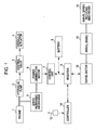
- Fig. 1 is a block diagram of a drive system and a control system, which are generally used in the hybrid shovel.
- a hydraulic pump 2 is connected to an engine 1, and oil delivered from the hydraulic pump 2 is supplied to a hydraulic actuator 4 (which is representatively illustrated here, although an actual machine includes hydraulic cylinders for a boom, an arm and a bucket and a hydraulic motor for traveling) through a control valve 3.
- a hydraulic actuator 4 which is representatively illustrated here, although an actual machine includes hydraulic cylinders for a boom, an arm and a bucket and a hydraulic motor for traveling
- An output of the engine 1 is applied to a power generation motor 6 through a speed increasing mechanism 5. Electric power produced by the power generation motor 6 is accumulated in a battery 8 through a control unit 7 which controls a voltage and a current. The electric power is further applied to a swivel motor 10 through an inverter 9.
- the power generation motor 6 also operates as a motor with the electric power stored in the battery 8, thereby assisting the engine 1 as required.
- the swivel motor 10 is provided with a swivel brake 11 for holding the swivel motor 10 in a stopped state.
- a rotating force (torque) of the swivel motor 10 is transmitted to an upper swivel structure of the shovel through a swivel speed reducing mechanism 12, whereupon the upper swivel structure is swiveled (rotated) clockwise or counterclockwise.
- a voltage of the battery 8 varies with the rotation of the swivel motor 10. If such a variation in the battery voltage occurs during a later-described process of determining a current leakage, there arises a possibility of erroneous detection.
- Reference numeral 13 denotes a swivel operating lever, which serves as one of operating means.
- a command signal is output from a controller 14 to the inverter 9, whereupon the swivel motor 10 is controlled.
- Fig. 2 illustrates the system configuration of a current leakage detector.
- the embodiment is constructed so as to detect, in a motor drive circuit for driving the swivel motor 10 by the battery 8 through the inverter 9, a current leakage between the motor drive circuit and a not-shown machine body (ground).
- machine body implies an upper frame of the upper swivel structure in the case of the shovel, the upper frame being grounded through a swivel bearing and a lower traveling structure.
- reference numerals 15 and 15 denote DC buses of the motor drive circuit
- 16 and 16 denote relays (contacts) disposed respectively in the buses 15 and 15 for connection to the battery 8
- 17 denotes a capacitor in the inverter
- 18 denotes a plurality of switching devices
- 10a denotes 3-phase AC lines between the inverter 9 and the swivel motor 10.
- a reference character r represents current leakage resistance that is generated with a current leakage.
- the inverter 9 is brought into an operated state upon turning-on of the switching devices 18. As a result, electric power is supplied to the swivel motor 10 and the swivel motor 10 is driven in accordance with the operation of the operating lever 13.
- the current leakage detector includes current-leakage detection signal output means 19 for applying a voltage signal (e.g., a pulse voltage at a particular frequency), which is adapted for detection of the current leakage, to the motor drive circuit, specifically between the DC buses 15, 15 and the body, for example, signal detection means 20 for detecting the applied voltage signal, current-leakage state determination means 21, an alarm unit 22 for issuing an alarm in accordance with a signal output from the current-leakage state determination means 21 when the occurrence of the current leakage is determined, lever operation detection means 23 for detecting whether the operating lever 13 is operated or not, and a swivel motor controller 24 for controlling start/stop of operation of the inverter 9 through the switching devices 18 in accordance with a signal from the current-leakage state determination means 21.
- a voltage signal e.g., a pulse voltage at a particular frequency
- the swivel motor controller 24 releases the swivel brake 11 when the operating lever is operated, and actuates the swivel brake 11 when the operating lever is not operated.
- the current-leakage state determination means 21 determines the occurrence or non-occurrence of the current leakage based on a crest value of the signal detected by the signal detection means 20 and on whether the swivel motor 10 (or the operating lever) is operated or not.
- the swivel motor 10 is operated in accordance with the operation of the operating lever 13. This implies that whether the swivel motor 10 is operated or not can be indirectly detected by detecting whether the operating lever 13 is operated or not.
- the current-leakage state determination means 21 operates the inverter 9 through the swivel motor controller 24 to bring the swivel motor into a state supplied with electric power, and then determines the occurrence or non-occurrence of the current leakage in the power supplied state when the following conditions are satisfied:
- a practical determination process can be performed as follows. Taking into account that the crest value of the detected signal (in the form of a pulse voltage) does not exceed a setting value in the current leakage state, but it exceeds the setting value in the current non-leakage state, the current-leakage state determination means 21 counts a time in which the crest value does not exceed the setting value (called a "low crest value time”) and a time in which the crest value exceeds the setting value (called a "high crest value time”).
- the low crest value time and the high crest value time may be each a time during which the low crest value or the high crest value is continuously detected, or a time derived from the numbers of pulses representing the low crest value or the high crest value.
- the lever operation i.e., the operation of the motor
- the lever operation detection means 23 When the lever operation (i.e., the operation of the motor) is detected by the lever operation detection means 23 during the determination process, the counting of the low crest value time and the high crest value time is interrupted (namely, the detection of the current leakage is suspended) in consideration of a risk that erroneous detection may occur due to a variation in the battery voltage.
- determination process steps (S1 to S22) are first executed, and whether the determination has already been made or not after power-on is then determined in step S23.
- step S23 If the determination result in step S23 is "NO" (i.e., if the determination has not yet been made even once), the switching devices 18 of the inverter 9 are turned on through the swivel motor controller 24 in Fig. 2 , whereupon the inverter 9 is brought into the operated state. Thus, electric power is supplied to the swivel motor 10 and a state capable of detecting the current leakage is established. In such a state, the determination process subsequent to step S1 is executed.
- step S23 determines whether the determination result in step S23 is "YES" (i.e., if the determination has already been made).
- step S1 The determination process steps will be described below, starting from step S1.
- step S1 whether the lever operation is performed or not is determined. If there is no lever operation (“NO”), the determination process advances to a current leakage detection flow, and if there is the lever operation (“YES”), the determination process advances to a current-leakage detection suspension flow.
- the term “count value” implies a count value of the low crest value time or the high crest value time
- the term “detection count value” implies a count value of the low crest value time
- the term “detection setting value” implies a threshold set for determining whether the detected crest value is the low crest value or not.
- the term “cancellation count value” implies a count value of the high crest value time
- the term “cancellation setting value” implies a threshold set for determining whether the detected crest value is the high crest value or not.
- count value 1 implies a current count value
- count value 2 implies a past count value that has been stored.
- detection count setting value implies a threshold set for the detection count value
- cancellation count setting value implies a threshold set for the cancellation count value.
- a count value of a lever operation time is first reset in step S2. The flow then shifts to step S3.
- step S3 it is determined whether the crest value of the detected pulse is not more than the detection setting value (i.e., whether it indicates the current leakage state). If the determination result is "YES" (i.e., if the current leakage state is indicated), the detection count value 1 is added in step S4 to count the low crest value time, and the cancellation count values 1 and 2 are reset in step S5. Thereafter, the flow shifts to step S6.
- step S3 determines whether the crest value of detected pulse is not less than the cancellation setting value. If the determination result in step S7 is "YES”, the flow advances in order of step S8, step S9, and step S6. If the determination result in step S7 is "NO”, the flow directly advances to step S6.
- step S8 the cancellation count value 1 is added to count the high crest value time.
- step S9 the detection count values 1 and 2 are reset.
- step S6 the count value of the low crest value time (i.e., the total value of the detection count values 1 and 2) is compared with a detection determination value that is a count value as a reference for determining the current leakage state. If the former is not less than the latter, it is determined in step S10 that the current leakage occurs.
- the alarm unit 23 in Fig. 2 is actuated in step S11 so as to notify an operator of the occurrence of the current leakage. Thereafter, the flow returns to step S1.
- step S6 determines whether the current leakage has not occur. If the former is not less than the latter (i.e., if the determination result in step S12 is "YES"), it is determined in step S13 that the current leakage does not occur. Thereafter, the flow shifts to step S23. If the determination result in step S12 is "NO", the flow directly shifts to step S23.
- step S14 it is determined whether the count value of the low crest value time during a period from start to interruption of the counting (i.e., the detection count value 1) is not less than the detection count setting value that serves as a threshold. If the determination result in step S14 is "NO” (i.e., if the former is less than the latter), the relevant count value is cleared in step S15. If the determination result in step S14 is "YES”. (i.e., if the former is not less than the latter), the count value is stored (namely, the detection count value 1 is added to the detection count value 2) in step S16.
- step S17 it is determined whether the count value of the high crest value time during the period from start to interruption of the counting (i.e., the cancellation count value 1) is not less than the cancellation count setting value that serves as a threshold. If the determination result in step S17 is "NO” (i.e., if the former is less than the latter), the relevant cancellation count value 1 is cleared in step S18. If the determination result in step S17 is "YES” (i.e., if the former is not less than the latter), the count value is stored (namely, the cancellation count value 1 is added to the cancellation count value 2) in step S19.
- step S20 the count value of the lever operation time is added.
- step S21 the resulting count value is compared with a lever operation time setting value that is a threshold set for the lever operation time.
- step S21 If the determination result in step S21 is "YES” (i.e., count value of lever operation time ⁇ lever operation time setting value), the detection count values 1 and 2 and the cancellation count values 1 and 2 are reset in step S22, following which the flow shifts to step S23. If the determination result in step S21 is "NO", the flow directly shifts to step S23.
- step S23 determines whether the determination result in step S23 is "NO" (i.e., if the determination has not yet been made).
- the inverter 9 is forcibly operated to supply the electric power to the swivel motor 10, thereby performing the detection of the current leakage, on condition that the power-on operation is performed, that the swivel motor 10 is in the stopped state, and that the determination as to the occurrence or non-occurrence of the current leakage has not yet been made even once after the power-on.
- the swivel motor drive circuit for which the supply of the electric power is cut off in the operated stopped state therefore, the reliable determination as to the current leakage can be made without being affected by the variation in the battery voltage.
- the current leakage detector is free from such a drawback as unduly delaying the start of work and deteriorating efficiency of the work.
- the low crest value time in which the crest value of the pulse voltage detected by the signal detection means 20 is not more than the setting value (i.e., the signal indicating the current leakage state) and the high crest value time in which the crest value of the detected pulse voltage is not less than the setting value (i.e., the signal indicating the normal state) are counted. If the count value of the low crest value time is not less than the setting value, it is determined that the current leakage state is present, and if the count value of the high crest value time is not less than the setting value, it is determined that the current leakage state is not present. Therefore, the influence of temporary noise can be eliminated and the determination as to the current leakage state or the normal state can be performed with higher reliability.
- steps S14 to S21 if respective count values of the low crest value time and the high crest value time during the period from start of the counting to its interruption due to the operation of the motor are not less than the setting values, those count values are stored to be ready for restart of the counting after the interruption.
- count values are less than the setting values, those count values are cleared because they are not enough as data for making the determination.
- the interruption of the counting of the low crest value time and the high crest value time continues for a setting time or longer, the count values are cleared on judgment that they are the past data to be discarded. As a result, accuracy in the determination can be increased.
- lever operation detection means 23 detects the operation state of the swivel motor 10 in the embodiment described above, the operation state of the swivel motor 10 may be directly detected instead.
- the present invention can be applied to not only the hybrid shovel, but also to a battery shovel employing only a battery as a power source and other battery-loaded construction machines than the shovels in a similar manner to that in the embodiment described above.
- An inverter is forcibly operated to supply electric power to a motor, thereby performing detection of a current leakage, on condition that a power-on operation is performed, that the motor is stopped, and that determination as to occurrence or non-occurrence of the current leakage has not yet been made even once after the power-on.
Applications Claiming Priority (1)
| Application Number | Priority Date | Filing Date | Title |
|---|---|---|---|
| JP2009206046A JP5365432B2 (ja) | 2009-09-07 | 2009-09-07 | 建設機械の漏電検出装置 |
Publications (3)
| Publication Number | Publication Date |
|---|---|
| EP2309637A2 true EP2309637A2 (fr) | 2011-04-13 |
| EP2309637A3 EP2309637A3 (fr) | 2012-02-15 |
| EP2309637B1 EP2309637B1 (fr) | 2012-12-26 |
Family
ID=43618634
Family Applications (1)
| Application Number | Title | Priority Date | Filing Date |
|---|---|---|---|
| EP10173883A Active EP2309637B1 (fr) | 2009-09-07 | 2010-08-24 | Détecteur de fuite de courant d'une machine de construction |
Country Status (4)
| Country | Link |
|---|---|
| US (1) | US8581596B2 (fr) |
| EP (1) | EP2309637B1 (fr) |
| JP (1) | JP5365432B2 (fr) |
| CN (1) | CN102012472B (fr) |
Families Citing this family (11)
| Publication number | Priority date | Publication date | Assignee | Title |
|---|---|---|---|---|
| JP5459713B2 (ja) * | 2010-07-06 | 2014-04-02 | 日立建機株式会社 | 電動式建設機械 |
| RU2596026C2 (ru) * | 2011-05-27 | 2016-08-27 | Линак А/С | Система линейного привода со средством для детектирования возгорания |
| JP5970898B2 (ja) * | 2012-03-26 | 2016-08-17 | コベルコ建機株式会社 | 動力伝達装置及びこれを備えたハイブリッド建設機械 |
| US9283852B2 (en) * | 2012-05-09 | 2016-03-15 | Schneider Electric USA, Inc. | Diagnostic receptacle for electric vehicle supply equipment |
| JP6051857B2 (ja) * | 2012-12-28 | 2016-12-27 | コベルコ建機株式会社 | 建設機械 |
| JP6628958B2 (ja) * | 2014-03-12 | 2020-01-15 | 住友重機械工業株式会社 | 電動旋回型建設機械 |
| JP6306913B2 (ja) * | 2014-03-19 | 2018-04-04 | 株式会社小松製作所 | 車載用電力供給システムの漏電検出装置及び油圧ショベル |
| JP6578753B2 (ja) * | 2015-06-15 | 2019-09-25 | コベルコ建機株式会社 | マグネット作業機械 |
| DE102017202191A1 (de) * | 2017-02-13 | 2018-08-16 | Robert Bosch Gmbh | Schaltung und Verfahren zum Erkennen eines schleichenden Kurzschlusses bei Brückenschaltungen |
| KR102062694B1 (ko) | 2017-08-17 | 2020-01-06 | 국방과학연구소 | 음성 복호화 시스템의 후처리 장치 및 방법 |
| JP6872474B2 (ja) * | 2017-12-15 | 2021-05-19 | 日立建機株式会社 | 建設機械 |
Citations (1)
| Publication number | Priority date | Publication date | Assignee | Title |
|---|---|---|---|---|
| WO2007007749A1 (fr) | 2005-07-12 | 2007-01-18 | Komatsu Ltd. | Détecteur de fuite de système d’alimentation monté dans véhicule |
Family Cites Families (14)
| Publication number | Priority date | Publication date | Assignee | Title |
|---|---|---|---|---|
| JPH07241002A (ja) * | 1994-02-24 | 1995-09-12 | Toyota Motor Corp | 電気自動車の漏電検出装置 |
| US6266901B1 (en) * | 1997-07-11 | 2001-07-31 | Komatsu Ltd. | Work machine |
| JP3399396B2 (ja) * | 1999-03-29 | 2003-04-21 | 日産自動車株式会社 | モータ制御システム |
| KR100466766B1 (ko) * | 1999-06-25 | 2005-01-24 | 코벨코 겐키 가부시키가이샤 | 하이브리드 건설 기계 및 그 제어 장치 |
| KR20010103998A (ko) * | 2000-05-12 | 2001-11-24 | 이계안 | 하이브리드 전기 자동차의 누전 차단장치 및 그 제어방법 |
| JP3986823B2 (ja) * | 2001-12-27 | 2007-10-03 | パナソニック・イーブイ・エナジー株式会社 | 漏電検出装置 |
| CN100446372C (zh) | 2004-07-07 | 2008-12-24 | 丰田自动车株式会社 | 能够检测流过驱动电路的电流的异常的电源装置 |
| JP4670413B2 (ja) * | 2004-07-07 | 2011-04-13 | トヨタ自動車株式会社 | 電源装置 |
| JP4430501B2 (ja) | 2004-09-29 | 2010-03-10 | トヨタ自動車株式会社 | 動力出力装置およびそれを備えた車両 |
| JP2006194804A (ja) | 2005-01-17 | 2006-07-27 | Ishikawajima Constr Mach Co | 漏電個所探査方法及び装置 |
| CN101228447A (zh) | 2005-08-29 | 2008-07-23 | 丰田自动车株式会社 | 绝缘电阻降低检测器和绝缘电阻降低检测器的故障自我诊断方法 |
| JP4635890B2 (ja) | 2006-02-03 | 2011-02-23 | トヨタ自動車株式会社 | 電源装置 |
| WO2008016179A1 (fr) * | 2006-08-04 | 2008-02-07 | Toyota Jidosha Kabushiki Kaisha | Système de détermination de résistance d'isolement, appareil de détermination de résistance d'isolement et procédé de détermination de résistance d'isolement |
| US7649360B2 (en) * | 2008-01-18 | 2010-01-19 | Gm Global Technology Operations, Inc. | Apparatus and systems for common mode voltage-based AC fault detection, verification and/or identification |
-
2009
- 2009-09-07 JP JP2009206046A patent/JP5365432B2/ja active Active
-
2010
- 2010-08-20 US US12/859,876 patent/US8581596B2/en active Active
- 2010-08-24 EP EP10173883A patent/EP2309637B1/fr active Active
- 2010-09-06 CN CN201010275323.3A patent/CN102012472B/zh active Active
Patent Citations (1)
| Publication number | Priority date | Publication date | Assignee | Title |
|---|---|---|---|---|
| WO2007007749A1 (fr) | 2005-07-12 | 2007-01-18 | Komatsu Ltd. | Détecteur de fuite de système d’alimentation monté dans véhicule |
Also Published As
| Publication number | Publication date |
|---|---|
| JP5365432B2 (ja) | 2013-12-11 |
| JP2011058177A (ja) | 2011-03-24 |
| US20110057596A1 (en) | 2011-03-10 |
| CN102012472B (zh) | 2014-04-02 |
| EP2309637B1 (fr) | 2012-12-26 |
| US8581596B2 (en) | 2013-11-12 |
| EP2309637A3 (fr) | 2012-02-15 |
| CN102012472A (zh) | 2011-04-13 |
Similar Documents
| Publication | Publication Date | Title |
|---|---|---|
| US8581596B2 (en) | Current leakage detector of construction machine | |
| EP2309636A2 (fr) | Détecteur de fuite de courant d'une machine de construction | |
| EP2181905B1 (fr) | Machine de travail hybride | |
| JP5509433B2 (ja) | ハイブリッド式建設機械及びこれに用いる補助制御装置 | |
| EP2400652B1 (fr) | Pelle hybride | |
| JP5184616B2 (ja) | ハイブリッド型作業機械 | |
| WO2007139167A1 (fr) | Engin de chantier | |
| EP2620556B1 (fr) | Machine de construction | |
| JP5779973B2 (ja) | ハイブリッド作業機械 | |
| WO2005095719A1 (fr) | Procede de freinage de rotation et dispositif pour machine-outils | |
| WO2016038910A1 (fr) | Machinerie de construction hybride | |
| KR20150118967A (ko) | 하이브리드 작업 기계 및 하이브리드 작업 기계의 정보 통지 제어 방법 | |
| JP5113603B2 (ja) | 電動式作業機械 | |
| JP2014058825A (ja) | 建設機械 | |
| JP2008038503A (ja) | ハイブリッド型作業機械 | |
| JP5778570B2 (ja) | 建設機械 | |
| US11945327B2 (en) | Charging control device, work machine, and charging control method | |
| EP3418454B1 (fr) | Engin de chantier | |
| JP2016217087A (ja) | 建設機械 | |
| JP2013139738A (ja) | アイドリングストップ装置 | |
| JP2020117897A (ja) | 作業機械 | |
| US20170096796A1 (en) | Slewing control device for hybrid construction machine and hybrid construction machine | |
| JP7042778B2 (ja) | 電動式建設機械 | |
| JP2020117869A (ja) | 作業機械 |
Legal Events
| Date | Code | Title | Description |
|---|---|---|---|
| PUAI | Public reference made under article 153(3) epc to a published international application that has entered the european phase |
Free format text: ORIGINAL CODE: 0009012 |
|
| 17P | Request for examination filed |
Effective date: 20100824 |
|
| AK | Designated contracting states |
Kind code of ref document: A2 Designated state(s): AL AT BE BG CH CY CZ DE DK EE ES FI FR GB GR HR HU IE IS IT LI LT LU LV MC MK MT NL NO PL PT RO SE SI SK SM TR |
|
| AX | Request for extension of the european patent |
Extension state: BA ME RS |
|
| PUAL | Search report despatched |
Free format text: ORIGINAL CODE: 0009013 |
|
| AK | Designated contracting states |
Kind code of ref document: A3 Designated state(s): AL AT BE BG CH CY CZ DE DK EE ES FI FR GB GR HR HU IE IS IT LI LT LU LV MC MK MT NL NO PL PT RO SE SI SK SM TR |
|
| AX | Request for extension of the european patent |
Extension state: BA ME RS |
|
| RIC1 | Information provided on ipc code assigned before grant |
Ipc: H02M 7/162 20060101AFI20120109BHEP Ipc: H02P 29/02 20060101ALI20120109BHEP Ipc: G01R 31/00 20060101ALI20120109BHEP Ipc: G01R 27/02 20060101ALI20120109BHEP Ipc: G01R 31/12 20060101ALI20120109BHEP Ipc: G01R 31/02 20060101ALI20120109BHEP |
|
| REG | Reference to a national code |
Ref country code: DE Ref legal event code: R079 Ref document number: 602010004286 Country of ref document: DE Free format text: PREVIOUS MAIN CLASS: H02M0007162000 Ipc: H02P0029020000 |
|
| GRAP | Despatch of communication of intention to grant a patent |
Free format text: ORIGINAL CODE: EPIDOSNIGR1 |
|
| RIC1 | Information provided on ipc code assigned before grant |
Ipc: H02M 7/162 20060101ALI20120531BHEP Ipc: H02P 29/02 20060101AFI20120531BHEP Ipc: G01R 27/02 20060101ALI20120531BHEP Ipc: B60L 3/04 20060101ALI20120531BHEP Ipc: G01R 31/00 20060101ALI20120531BHEP |
|
| GRAS | Grant fee paid |
Free format text: ORIGINAL CODE: EPIDOSNIGR3 |
|
| GRAA | (expected) grant |
Free format text: ORIGINAL CODE: 0009210 |
|
| AK | Designated contracting states |
Kind code of ref document: B1 Designated state(s): AL AT BE BG CH CY CZ DE DK EE ES FI FR GB GR HR HU IE IS IT LI LT LU LV MC MK MT NL NO PL PT RO SE SI SK SM TR |
|
| REG | Reference to a national code |
Ref country code: GB Ref legal event code: FG4D |
|
| REG | Reference to a national code |
Ref country code: CH Ref legal event code: EP |
|
| REG | Reference to a national code |
Ref country code: AT Ref legal event code: REF Ref document number: 590899 Country of ref document: AT Kind code of ref document: T Effective date: 20130115 |
|
| REG | Reference to a national code |
Ref country code: DE Ref legal event code: R096 Ref document number: 602010004286 Country of ref document: DE Effective date: 20130314 |
|
| PG25 | Lapsed in a contracting state [announced via postgrant information from national office to epo] |
Ref country code: FI Free format text: LAPSE BECAUSE OF FAILURE TO SUBMIT A TRANSLATION OF THE DESCRIPTION OR TO PAY THE FEE WITHIN THE PRESCRIBED TIME-LIMIT Effective date: 20121226 Ref country code: HR Free format text: LAPSE BECAUSE OF FAILURE TO SUBMIT A TRANSLATION OF THE DESCRIPTION OR TO PAY THE FEE WITHIN THE PRESCRIBED TIME-LIMIT Effective date: 20121226 Ref country code: NO Free format text: LAPSE BECAUSE OF FAILURE TO SUBMIT A TRANSLATION OF THE DESCRIPTION OR TO PAY THE FEE WITHIN THE PRESCRIBED TIME-LIMIT Effective date: 20130326 Ref country code: SE Free format text: LAPSE BECAUSE OF FAILURE TO SUBMIT A TRANSLATION OF THE DESCRIPTION OR TO PAY THE FEE WITHIN THE PRESCRIBED TIME-LIMIT Effective date: 20121226 Ref country code: LT Free format text: LAPSE BECAUSE OF FAILURE TO SUBMIT A TRANSLATION OF THE DESCRIPTION OR TO PAY THE FEE WITHIN THE PRESCRIBED TIME-LIMIT Effective date: 20121226 |
|
| REG | Reference to a national code |
Ref country code: AT Ref legal event code: MK05 Ref document number: 590899 Country of ref document: AT Kind code of ref document: T Effective date: 20121226 |
|
| REG | Reference to a national code |
Ref country code: LT Ref legal event code: MG4D |
|
| REG | Reference to a national code |
Ref country code: NL Ref legal event code: VDEP Effective date: 20121226 |
|
| PG25 | Lapsed in a contracting state [announced via postgrant information from national office to epo] |
Ref country code: GR Free format text: LAPSE BECAUSE OF FAILURE TO SUBMIT A TRANSLATION OF THE DESCRIPTION OR TO PAY THE FEE WITHIN THE PRESCRIBED TIME-LIMIT Effective date: 20130327 Ref country code: LV Free format text: LAPSE BECAUSE OF FAILURE TO SUBMIT A TRANSLATION OF THE DESCRIPTION OR TO PAY THE FEE WITHIN THE PRESCRIBED TIME-LIMIT Effective date: 20121226 Ref country code: SI Free format text: LAPSE BECAUSE OF FAILURE TO SUBMIT A TRANSLATION OF THE DESCRIPTION OR TO PAY THE FEE WITHIN THE PRESCRIBED TIME-LIMIT Effective date: 20121226 |
|
| PG25 | Lapsed in a contracting state [announced via postgrant information from national office to epo] |
Ref country code: AT Free format text: LAPSE BECAUSE OF FAILURE TO SUBMIT A TRANSLATION OF THE DESCRIPTION OR TO PAY THE FEE WITHIN THE PRESCRIBED TIME-LIMIT Effective date: 20121226 Ref country code: IS Free format text: LAPSE BECAUSE OF FAILURE TO SUBMIT A TRANSLATION OF THE DESCRIPTION OR TO PAY THE FEE WITHIN THE PRESCRIBED TIME-LIMIT Effective date: 20130426 Ref country code: SK Free format text: LAPSE BECAUSE OF FAILURE TO SUBMIT A TRANSLATION OF THE DESCRIPTION OR TO PAY THE FEE WITHIN THE PRESCRIBED TIME-LIMIT Effective date: 20121226 Ref country code: ES Free format text: LAPSE BECAUSE OF FAILURE TO SUBMIT A TRANSLATION OF THE DESCRIPTION OR TO PAY THE FEE WITHIN THE PRESCRIBED TIME-LIMIT Effective date: 20130406 Ref country code: EE Free format text: LAPSE BECAUSE OF FAILURE TO SUBMIT A TRANSLATION OF THE DESCRIPTION OR TO PAY THE FEE WITHIN THE PRESCRIBED TIME-LIMIT Effective date: 20121226 Ref country code: CZ Free format text: LAPSE BECAUSE OF FAILURE TO SUBMIT A TRANSLATION OF THE DESCRIPTION OR TO PAY THE FEE WITHIN THE PRESCRIBED TIME-LIMIT Effective date: 20121226 Ref country code: BE Free format text: LAPSE BECAUSE OF FAILURE TO SUBMIT A TRANSLATION OF THE DESCRIPTION OR TO PAY THE FEE WITHIN THE PRESCRIBED TIME-LIMIT Effective date: 20121226 Ref country code: BG Free format text: LAPSE BECAUSE OF FAILURE TO SUBMIT A TRANSLATION OF THE DESCRIPTION OR TO PAY THE FEE WITHIN THE PRESCRIBED TIME-LIMIT Effective date: 20130326 |
|
| PG25 | Lapsed in a contracting state [announced via postgrant information from national office to epo] |
Ref country code: RO Free format text: LAPSE BECAUSE OF FAILURE TO SUBMIT A TRANSLATION OF THE DESCRIPTION OR TO PAY THE FEE WITHIN THE PRESCRIBED TIME-LIMIT Effective date: 20121226 Ref country code: PL Free format text: LAPSE BECAUSE OF FAILURE TO SUBMIT A TRANSLATION OF THE DESCRIPTION OR TO PAY THE FEE WITHIN THE PRESCRIBED TIME-LIMIT Effective date: 20121226 Ref country code: PT Free format text: LAPSE BECAUSE OF FAILURE TO SUBMIT A TRANSLATION OF THE DESCRIPTION OR TO PAY THE FEE WITHIN THE PRESCRIBED TIME-LIMIT Effective date: 20130426 Ref country code: NL Free format text: LAPSE BECAUSE OF FAILURE TO SUBMIT A TRANSLATION OF THE DESCRIPTION OR TO PAY THE FEE WITHIN THE PRESCRIBED TIME-LIMIT Effective date: 20121226 |
|
| PG25 | Lapsed in a contracting state [announced via postgrant information from national office to epo] |
Ref country code: DK Free format text: LAPSE BECAUSE OF FAILURE TO SUBMIT A TRANSLATION OF THE DESCRIPTION OR TO PAY THE FEE WITHIN THE PRESCRIBED TIME-LIMIT Effective date: 20121226 |
|
| PLBE | No opposition filed within time limit |
Free format text: ORIGINAL CODE: 0009261 |
|
| STAA | Information on the status of an ep patent application or granted ep patent |
Free format text: STATUS: NO OPPOSITION FILED WITHIN TIME LIMIT |
|
| PG25 | Lapsed in a contracting state [announced via postgrant information from national office to epo] |
Ref country code: CY Free format text: LAPSE BECAUSE OF FAILURE TO SUBMIT A TRANSLATION OF THE DESCRIPTION OR TO PAY THE FEE WITHIN THE PRESCRIBED TIME-LIMIT Effective date: 20121226 |
|
| 26N | No opposition filed |
Effective date: 20130927 |
|
| REG | Reference to a national code |
Ref country code: DE Ref legal event code: R097 Ref document number: 602010004286 Country of ref document: DE Effective date: 20130927 |
|
| PG25 | Lapsed in a contracting state [announced via postgrant information from national office to epo] |
Ref country code: MC Free format text: LAPSE BECAUSE OF FAILURE TO SUBMIT A TRANSLATION OF THE DESCRIPTION OR TO PAY THE FEE WITHIN THE PRESCRIBED TIME-LIMIT Effective date: 20121226 |
|
| REG | Reference to a national code |
Ref country code: IE Ref legal event code: MM4A |
|
| PG25 | Lapsed in a contracting state [announced via postgrant information from national office to epo] |
Ref country code: IE Free format text: LAPSE BECAUSE OF NON-PAYMENT OF DUE FEES Effective date: 20130824 |
|
| REG | Reference to a national code |
Ref country code: CH Ref legal event code: PL |
|
| PG25 | Lapsed in a contracting state [announced via postgrant information from national office to epo] |
Ref country code: CH Free format text: LAPSE BECAUSE OF NON-PAYMENT OF DUE FEES Effective date: 20140831 Ref country code: LI Free format text: LAPSE BECAUSE OF NON-PAYMENT OF DUE FEES Effective date: 20140831 |
|
| PG25 | Lapsed in a contracting state [announced via postgrant information from national office to epo] |
Ref country code: SM Free format text: LAPSE BECAUSE OF FAILURE TO SUBMIT A TRANSLATION OF THE DESCRIPTION OR TO PAY THE FEE WITHIN THE PRESCRIBED TIME-LIMIT Effective date: 20121226 |
|
| PG25 | Lapsed in a contracting state [announced via postgrant information from national office to epo] |
Ref country code: TR Free format text: LAPSE BECAUSE OF FAILURE TO SUBMIT A TRANSLATION OF THE DESCRIPTION OR TO PAY THE FEE WITHIN THE PRESCRIBED TIME-LIMIT Effective date: 20121226 Ref country code: MT Free format text: LAPSE BECAUSE OF FAILURE TO SUBMIT A TRANSLATION OF THE DESCRIPTION OR TO PAY THE FEE WITHIN THE PRESCRIBED TIME-LIMIT Effective date: 20121226 |
|
| PG25 | Lapsed in a contracting state [announced via postgrant information from national office to epo] |
Ref country code: MK Free format text: LAPSE BECAUSE OF FAILURE TO SUBMIT A TRANSLATION OF THE DESCRIPTION OR TO PAY THE FEE WITHIN THE PRESCRIBED TIME-LIMIT Effective date: 20121226 Ref country code: HU Free format text: LAPSE BECAUSE OF FAILURE TO SUBMIT A TRANSLATION OF THE DESCRIPTION OR TO PAY THE FEE WITHIN THE PRESCRIBED TIME-LIMIT; INVALID AB INITIO Effective date: 20100824 Ref country code: LU Free format text: LAPSE BECAUSE OF NON-PAYMENT OF DUE FEES Effective date: 20130824 |
|
| REG | Reference to a national code |
Ref country code: FR Ref legal event code: PLFP Year of fee payment: 7 |
|
| REG | Reference to a national code |
Ref country code: FR Ref legal event code: PLFP Year of fee payment: 8 |
|
| REG | Reference to a national code |
Ref country code: FR Ref legal event code: PLFP Year of fee payment: 9 |
|
| PG25 | Lapsed in a contracting state [announced via postgrant information from national office to epo] |
Ref country code: AL Free format text: LAPSE BECAUSE OF FAILURE TO SUBMIT A TRANSLATION OF THE DESCRIPTION OR TO PAY THE FEE WITHIN THE PRESCRIBED TIME-LIMIT Effective date: 20121226 |
|
| PGFP | Annual fee paid to national office [announced via postgrant information from national office to epo] |
Ref country code: IT Payment date: 20230711 Year of fee payment: 14 Ref country code: GB Payment date: 20230706 Year of fee payment: 14 |
|
| PGFP | Annual fee paid to national office [announced via postgrant information from national office to epo] |
Ref country code: FR Payment date: 20230703 Year of fee payment: 14 Ref country code: DE Payment date: 20230627 Year of fee payment: 14 |