EP2309566B1 - Organic light-emitting device - Google Patents
Organic light-emitting device Download PDFInfo
- Publication number
- EP2309566B1 EP2309566B1 EP10187087A EP10187087A EP2309566B1 EP 2309566 B1 EP2309566 B1 EP 2309566B1 EP 10187087 A EP10187087 A EP 10187087A EP 10187087 A EP10187087 A EP 10187087A EP 2309566 B1 EP2309566 B1 EP 2309566B1
- Authority
- EP
- European Patent Office
- Prior art keywords
- group
- layer
- substituted
- emitting device
- organic light
- Prior art date
- Legal status (The legal status is an assumption and is not a legal conclusion. Google has not performed a legal analysis and makes no representation as to the accuracy of the status listed.)
- Active
Links
Images


Classifications
-
- H—ELECTRICITY
- H10—SEMICONDUCTOR DEVICES; ELECTRIC SOLID-STATE DEVICES NOT OTHERWISE PROVIDED FOR
- H10K—ORGANIC ELECTRIC SOLID-STATE DEVICES
- H10K50/00—Organic light-emitting devices
- H10K50/80—Constructional details
- H10K50/805—Electrodes
- H10K50/81—Anodes
- H10K50/818—Reflective anodes, e.g. ITO combined with thick metallic layers
-
- H—ELECTRICITY
- H10—SEMICONDUCTOR DEVICES; ELECTRIC SOLID-STATE DEVICES NOT OTHERWISE PROVIDED FOR
- H10K—ORGANIC ELECTRIC SOLID-STATE DEVICES
- H10K50/00—Organic light-emitting devices
- H10K50/10—OLEDs or polymer light-emitting diodes [PLED]
- H10K50/14—Carrier transporting layers
-
- H—ELECTRICITY
- H10—SEMICONDUCTOR DEVICES; ELECTRIC SOLID-STATE DEVICES NOT OTHERWISE PROVIDED FOR
- H10K—ORGANIC ELECTRIC SOLID-STATE DEVICES
- H10K50/00—Organic light-emitting devices
- H10K50/10—OLEDs or polymer light-emitting diodes [PLED]
- H10K50/17—Carrier injection layers
-
- H—ELECTRICITY
- H10—SEMICONDUCTOR DEVICES; ELECTRIC SOLID-STATE DEVICES NOT OTHERWISE PROVIDED FOR
- H10K—ORGANIC ELECTRIC SOLID-STATE DEVICES
- H10K50/00—Organic light-emitting devices
- H10K50/80—Constructional details
- H10K50/805—Electrodes
- H10K50/81—Anodes
- H10K50/816—Multilayers, e.g. transparent multilayers
-
- H—ELECTRICITY
- H10—SEMICONDUCTOR DEVICES; ELECTRIC SOLID-STATE DEVICES NOT OTHERWISE PROVIDED FOR
- H10K—ORGANIC ELECTRIC SOLID-STATE DEVICES
- H10K2102/00—Constructional details relating to the organic devices covered by this subclass
- H10K2102/10—Transparent electrodes, e.g. using graphene
- H10K2102/101—Transparent electrodes, e.g. using graphene comprising transparent conductive oxides [TCO]
- H10K2102/103—Transparent electrodes, e.g. using graphene comprising transparent conductive oxides [TCO] comprising indium oxides, e.g. ITO
Definitions
- Embodiments relate to an organic light-emitting device.
- OLEDs which are self-emitting devices, have advantages, e.g., a wide viewing angle, excellent contrast, quick response, high brightness, excellent driving voltage characteristics, and an ability to provide multicolored images.
- a typical OLED has a structure including, e.g., a substrate, and an anode, a hole transport layer (HTL), an emission layer (EML), an electron transport layer (ETL), and a cathode, which are sequentially stacked on the substrate.
- the HTL, the EML, and the ETL may be organic thin films formed of organic compounds.
- An anode electrode may include an Al-Ni-La alloy film being directly in contact with an ITO film ( T. Kugimiya et al., SID 2009, Los Angeles, pages 1681 - 1684 ).
- An operating principle of an OLED having the above-described structure is as follows.
- an organic light-emitting device including a substrate; a first electrode on the substrate; a second electrode; an organic layer between the first electrode and the second electrode; and a carbonaceous material-containing layer between the first electrode and the organic layer
- the first electrode includes an aluminum (Al)-based reflective layer and a transparent conductive layer sequentially stacked in this order on the substrate
- the Al-based reflective layer including a first element and nickel (Ni) and the first element includes at least one of lanthanum (La), cerium (Ce), praseodymium (Pr), promethium (Pm), samarium (Sm), europium (Eu), gadolinium (Gd), terbium (Tb), dysprosium (Dy), holmium (Ho), erbium (Er), thulium (Tm), ytterbium (Yb), and lutetium (Lu).
- La lanthanum
- Ce cerium
- Pr praseodymium
- Pm
- the Al-based reflective layer may include an Ain phase, x being 2.5 to 3.5. x may be 3.
- the organic light-emitting device further includes a nickel (Ni)-rich oxide layer on a surface of the Al-based reflective layer that faces the transparent conductive layer.
- the nickel (Ni) may be included in the Al-based reflective layer in an amount of 0.6 wt% to 5 wt%.
- the first element may be lanthanum (La).
- the first element may be included in the Al-based reflective layer in an amount of 0.1 wt% to 3 wt%.
- the Al-based reflective layer may include lanthanum (La), nickel (Ni), and aluminum (Al), the lanthanum (La) may be included in the Al-based reflective layer in an amount of 0.1 wt% to 3 wt%, and the nickel (Ni) may be included in the Al-based reflective layer in an amount of 0.6 wt% to 5 wt%.
- the transparent conductive layer may include or consist of indium tin oxide (ITO) or tin oxide (SnO 2 ).
- the carbonaceous material-containing layer includes a carbonaceous material including at least one of a fullerene-based compound, a metal-containing fullerene-based complex, carbon nanotubes, carbon fiber, carbon black, graphite, carbine, MgC 60 , CaC 60 , and SiC 60 .
- the carbonaceous material may include C 60 .
- the first electrode may further include a second element-containing zinc oxide layer, the second element in the second element-containing zinc oxide layer including at least one of aluminum (Al), indium (In), gallium (Ga), germanium (Ge), gadolinium (Gd), zirconium (Zr), molybdenum (Mo), and nickel (Ni).
- a second element-containing zinc oxide layer the second element in the second element-containing zinc oxide layer including at least one of aluminum (Al), indium (In), gallium (Ga), germanium (Ge), gadolinium (Gd), zirconium (Zr), molybdenum (Mo), and nickel (Ni).
- the second element may include aluminum (Al).
- the Al-based reflective layer including the first element and nickel (Ni), the transparent conductive layer, and the second element-containing zinc oxide layer may be sequentially stacked in this order on the substrate.
- the second element may be included in the second element-containing zinc oxide layer in an amount of 0.5 to 10 parts by weight, based on 100 parts by weight of the second element-containing zinc oxide layer.
- FIG. 1 illustrates a schematic sectional view of an organic light-emitting device (OLED) 10 according to an embodiment.
- the OLED 10 according to the present embodiment includes a substrate 1, a first electrode 5, a carbonaceous material-containing layer 6, an organic layer 7, and a second electrode 9, which are sequentially stacked in this order.
- the first electrode 5 includes an aluminum (Al)-based reflective layer 5a and a transparent conductive layer 5b sequentially stacked on the substrate 1.
- the Al-based reflective layer 5a includes Al, a first element, and nickel (Ni).
- the substrate 1, which may be any substrate suitable for organic light emitting devices, may be a glass substrate or a transparent plastic substrate with excellent mechanical strength, thermal stability, transparency, surface smoothness, ease of handling, and water impermeability.
- the first element in the Al-based reflective layer 5a includes at least one of lanthanum (La), cerium (Ce), praseodymium (Pr), promethium (Pm), samarium (Sm), europium (Eu), gadolinium (Gd), terbium (Tb), dysprosium (Dy), holmium (Ho), erbium (Er), thulium (Tm), ytterbium (Yb), and lutetium (Lu).
- La lanthanum
- Ce cerium
- Pr praseodymium
- Pm promethium
- Sm samarium
- Eu europium
- Gd gadolinium
- Tb terbium
- Dy dysprosium
- Ho holmium
- Er erbium
- Tm thulium
- Yb ytterbium
- Lu lutetium
- the Al-based reflective layer 5a may have a high reflexibility and/or reflectance, and thus may improve luminescent efficiency of the OLED.
- the Al-based reflective layer 5a may have high thermal stability due to inherent properties of Al.
- the Al-based reflective layer 5a may have excellent durability even when exposed to a high-temperature manufacturing process.
- the Al-based reflective layer 5a may have excellent adhesive characteristics with respect to an organic layer or an inorganic layer formed adjacent thereto.
- the Al-based reflective layer 5a and the transparent conductive layer 5b may contact each other. However, galvanic corrosion caused by a potential difference between the Al-based reflective layer 5a and the transparent conductive layer 5b may substantially not occur.
- galvanic corrosion may occur due to a potential difference between two different metals adjacent to each other, thereby causing current to flow and electricity to be generated.
- One of two different metals electrically in contact with each other having a relatively greater activity (lower potential) due to different work functions at the interface thereof may function as a cathode and the other one having a relatively lower activity (greater potential) may function as an anode.
- both metals When the two metals are exposed to a corrosive solution, both metals may be corroded due to the potential difference therebetween. This is referred to as galvanic corrosion.
- the cathode having a greater activity may be corroded faster than when exclusively used.
- the anode having a lower activity may be corroded slower than when exclusively used.
- the Al-based reflective layer 5a includes the first element, which will be described later in detail, such galvanic corrosion may substantially not occur at the interface between the Al-based reflective layer 5a and the transparent conductive layer 5b.
- the OLED according to the current embodiment may have excellent image quality.
- the Al-based reflective layer 5a may include nickel (Ni).
- the Al-based reflective layer 5a may include an Al x Ni phase wherein x is about 2.5 to about 3.5.
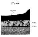
- FIG. 2A illustrates a transmission electron microscopic (TEM) image of a cross-section of an Al-based reflective layer (layer A) formed on a titanium (Ti) layer (layer B), wherein the Al-based reflective layer includes 2 wt% of nickel (Ni) and 0.35 wt% of lanthanum (La) and
- FIG. 2B shows a scanning transmission electron microscope (STEM)-high-angle annular dark-field (HAADF) image of the aluminum (Al)-based reflective film shown in FIG. 2A .
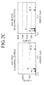
- FIG. 2C illustrates a result of semi-quantitative energy dispersive X-ray spectroscopy (EDS) on abnormally grown Al x Ni crystals (at first and second measurement sites) in FIG. 2A .
- EDS semi-quantitative energy dispersive X-ray spectroscopy
- the Al-based reflective layer presumably includes an Al x Ni phase wherein x is about 3.
- the Al x Ni phase may contact the transparent conductive layer 5b.
- a Ni-rich oxide layer is further disposed on a surface of the Al-based reflective layer 5a facing the transparent conductive layer 5b.
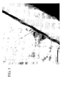
- FIG. 3 illustrates a TEM image of a cross-section of a structure including an Al-based reflective layer (region C) and a transparent ITO conductive layer (region D) sequentially formed on a TFT substrate, wherein the Al-based reflective layer includes 2 wt% of nickel (Ni) and 0.35 wt% of lanthanum (La).
- a linear region, denoted by "E', between the Al-based reflective layer and the transparent ITO conductive layer corresponds to a Ni-rich oxide layer having a thickness of about 7 nm to about 8 nm.
- the Ni may be included in the Al-based reflective layer 5a in an amount of about 0.6 wt% to about 5 wt%, e.g., about 1 wt% to about 4 wt%. Maintaining the amount of Ni in the Al-based reflective layer 5a at about 0.6 wt% to about 5 wt% may help ensure that the contact resistance between the Al-based reflective layer 5a and the transparent conductive layer 5b may be stabilized and reflectivity and resistance to chemicals of the Al-based reflective layer 5a may be substantially not reduced. In an implementation, the amount of Ni in the Al-based reflective layer 5a may be about 2 wt%.
- the Al-based reflective layer 5a may include the first element, in addition to Ni having such a function as described above.
- the first element includes lanthanum (La), cerium (Ce), praseodymium (Pr), promethium (Pm), samarium (Sm), europium (Eu), gadolinium (Gd), terbium (Tb), dysprosium (Dy), holmium (Ho), erbium (Er), thulium (Tm), ytterbium (Yb), and/or lutetium (Lu).
- La lanthanum
- Ce cerium
- Pr praseodymium
- Pm promethium
- Sm samarium
- Eu europium
- Gd gadolinium
- Tb terbium
- Dy dysprosium
- Ho holmium
- Er erbium
- Tm thulium
- Yb ytterbium
- Lu lutetium
- the Al-based reflective layer 5a may include the first element, the Al-based reflective layer 5a may have excellent thermal stability and galvanic corrosion may be advantageously suppressed.
- the first element may be lanthanum (La).
- the first element may be included in the Al-based reflective layer 5a in an amount of about 0.1 wt% to about 3 wt%, e.g., about 0.1 wt% to about 1 wt%. Maintaining the amount of the first element at about 0.1 wt% to about 3 wt% may help ensure that neither the thermal stability of Al in the Al-based reflective layer 5a nor the reflectivity of the Al-based reflective layer 5a is substantially reduced.
- the amount of the first element is not limited to the above range. In an implementation, the amount of the first element may be, e.g., about 0.30 wt% to about 0.35 wt%.
- the Al-based reflective layer 5a may have a thickness of about 50 nm or greater, e.g., about 100 nm to about 500 nm. Maintaining the thickness of the Al-based reflective layer 5a at about 50 nm or greater may help ensure that light generated in the organic layer 7 does not pass through the Al-based reflective layer 5a, so that the luminescent efficiency of the OLED is not substantially reduced.
- the transparent conductive layer 5b may be formed of a transparent conductive metal oxide.
- the transparent conductive metal oxides may include, e.g., ITO and tin oxide (Sn0 2 ).
- the transparent conductive layer 5b may be formed of ITO.
- the transparent conductive layer 5b may have a thickness of about 5 nm to about 100 nm, e.g., about 7 nm to about 80 nm. Maintaining the thickness of the transparent conductive layer 5b at about 5 nm to about 100 nm may help ensure that a reduction in the reflectivity of the Al-based reflective layer 5a is minimized and the OLED has excellent efficiency.
- the carbonaceous material-containing layer 6 is formed on the transparent conductive layer 5a.
- the carbonaceous material-containing layer 6 effectively injects and transports holes from the first electrode 5 into the organic layer 7.
- the OLED including the Al-based reflective layer 5a and the transparent conductive layer 5b in the first electrode 5 as described above has excellent efficiency and power consumption characteristics.
- a high refractive index (>1.8) of the carbonaceous material-containing layer 6, which is high enough to compensate for a phase difference of light reflected from the Al-based reflective layer 5a, may also provide excellent efficiency and power consumption characteristics to the OLED.
- a carbonaceous material in the carbonaceous material-containing layer 6 may include, e.g., an allotrope of carbon consisting of about 50 to about 600 carbon atoms or a metal-containing carbonaceous compound.
- the carbonaceous material includes a fullerene-based compound, a metal-containing fullerene-based complex, carbon nanotubes, carbon fiber, carbon black, graphite, carbine, MgC 60 , CaC 60 , and/or SiC 60 .
- the carbonaceous material may be a C 60 -C 500 fullerene-based compound, especially C 60 .
- the carbonaceous material-containing layer 6 may have a thickness of about 1 ⁇ to about 300 ⁇ . Maintaining the thickness of the carbonaceous material-containing layer 6 at about 1 ⁇ to about 300 ⁇ may help ensure that an OLED emitting red, green, and/or blue light having high color purity at a high efficiency is attained.
- the carbonaceous material-containing layer 6 may have a thickness of about 3 ⁇ to about 100 ⁇ . In another implementation, the carbonaceous material-containing layer 6 may have a thickness of about 3 ⁇ to about 30 ⁇ .
- the organic layer 7 may be formed on the carbonaceous material-containing layer 6, as described above.
- the term "organic layer” used throughout the specification refers to any intervening layer between the first electrode 5 and the second electrode 9.
- the organic layer 7 may not be formed of pure organic materials and may include a metal complex.
- the organic layer 7 may include at least one layer selected from the group consisting of a hole injection layer (HIL), a hole transport layer (HTL), an emission layer (EML), a hole blocking layer (HBL), an electron transport layer (ETL) and an electron injection layer (EIL).
- HIL hole injection layer
- HTL hole transport layer
- EML emission layer
- HBL hole blocking layer
- ETL electron transport layer
- EIL electron injection layer
- the organic layer 7 may have a stacked structure including, e.g., a HIL, a HTL, an EML, an ETL, and an EIL, which are stacked in this order on the carbonaceous material-containing layer 6.
- the organic layer 7 may have a stacked structure including, e.g., a HTL, an EML, an ETL, and an EIL, which are stacked in this order on the carbonaceous material-containing layer 6.
- the HIL may be formed on the carbonaceous material-containing layer 6 by using, e.g., vacuum deposition, spin coating, casting, Langmuir-Blodgett (LB) deposition, or the like.
- vacuum deposition spin coating
- casting Langmuir-Blodgett
- deposition conditions may vary according to a compound that is used to form the HIL and the structure and thermal properties of the HIL to be formed. In general, however, conditions for vacuum deposition may include a deposition temperature of about 100 to about 500 °C, a vacuum pressure of about 10- 8 to about 10 -3 torr, and a deposition rate of about 0.01 to about 100 ⁇ /sec.
- the coating conditions may vary according to a compound that is used to form the HIL, and the structure and thermal properties of the HIL to be formed. In general, however, conditions for spin coating may include a coating rate of about 2,000 to about 5,000 rpm and a heat treatment temperature of about 80 to about 200 °C, wherein the heat treatment is performed to remove a solvent after coating.
- the HIL may be formed of any material suitable for forming a HIL.
- the material for forming the HIL may include, e.g., a phthalocyanine compound such as copper phthalocyanine, 4,4',4"-tris(3-methylphenylphenylamino) triphenylamine (m-MTDATA), N,N'-di(1-naphthyl)-N,N'-diphenylbenzidine (NPB), TDATA, 2T-NATA, polyaniline/dodecylbenzenesulfonic acid (Pani/DBSA), poly(3,4-ethylenedioxythiophene)/poly(4-styrenesulfonate) (PEDOT/PSS), polyaniline/camphor sulfonicacid (Pani/CSA), and polyaniline)/poly(4-styrenesulfonate (PANI/PSS).
- a phthalocyanine compound such as copper phthalocyan
- the HIL may have a thickness of about 50 ⁇ to about 10,000 ⁇ , e.g., a thickness of about 50 ⁇ to about 2,500 ⁇ . Maintaining the thickness of the HIL at about 50 ⁇ to about 10,000 ⁇ may help ensure that the HIL has an excellent hole injecting ability without a substantial increase in driving voltage.
- a HTL may be formed on the HIL by using, e.g., vacuum deposition, spin coating, casting, Langmuir-Blodgett (LB) deposition, or the like.
- the conditions for deposition and coating may be similar to those for the formation of the HIL, although the conditions for the deposition and coating may vary according to the material that is used to form the HTL.
- a material for forming the HTL may be a compound represented by Formula 41 or 42 below.
- R 10 may be -(Ar 1 ) n -Ar 2 .
- R 16 may be -(Ar 11 ) m Ar 12 .
- Ar 1 , Ar 11 , L 1 and L 11 may each independently be, e.g., a substituted or unsubstituted C 1 -C 30 alkylene group, a substituted or unsubstituted C 2 -C 30 alkenylene group, a substituted or unsubstituted C 5 -C 30 arylene group, a substituted or unsubstituted C 4 -C 30 heteroarylene group, and/or a group represented by -N(Q 1 )-.
- n, m, a, and b may each independently be an integer from 0 to 10.
- R 1 through R 3 , R 11 through R 15 , R 17 , R 18 , R 21 through R 29 , Ar 2 , Ar 12 , and Q 1 may each independently be, e.g., hydrogen, a halogen atom, a hydroxyl group, a cyano group, a substituted or unsubstituted C 1 -C 30 alkyl group, a substituted or unsubstituted C 2 -C 30 alkenyl group, a substituted or unsubstituted C 2 -C 30 alkynyl group, a substituted or unsubstituted C 1 -C 30 alkoxy group, a substituted or unsubstituted C 1 -C 30 alkylthiol group, a substituted or unsubstituted C 5 -C 30 aryl group, a substituted or unsubstituted C 4 -C
- Q 2 and Q 3 may each independently be hydrogen, a halogen atom, a hydroxyl group, a cyano group, a substituted or unsubstituted C 1 -C 30 alkyl group, a substituted or unsubstituted C 2 -C 30 alkenyl group, a substituted or unsubstituted C 2 -C 30 alkynyl group, a substituted or unsubstituted C 1 -C 30 alkoxy group, a substituted or unsubstituted C 1 -C 30 alkylthiol group, a substituted or unsubstituted C 5 -C 30 aryl group, and a substituted or unsubstituted C 4 -C 30 heteroaryl group, wherein n groups of Ar 1 in -(Ar l ) n - are identical to or different from each other, m groups of Ar 11 in -(Ar 11 ) m- are identical to or different from each other, a
- Ar 1 in the formula -(Ar 1 ) n Ar 2 - for R 10 and Ar 11 in the formula -(Ar 11 ) m -Ar 12 - for R 16 may include a substituted or unsubstituted C 1 -C l0 alkylene group, a substituted or unsubstituted C 2 -C l0 alkenylene group, a substituted or unsubstituted phenylene group, a substituted or unsubstituted pentalenylene group, a substituted or unsubstituted indenylene group, a substituted or unsubstituted naphthylene group, a substituted or unsubstituted azulenylene group, a substituted or unsubstituted heptalenylene group, a substituted or unsubstituted indacenylene group, a substituted or unsubstituted acenaphthylene group, a substituted
- Q 1 may include, e.g., hydrogen, a halogen atom, a hydroxyl group, a cyano group, a substituted or unsubstituted C 1 -C l0 alkyl group, a substituted or unsubstituted C 2 -C 10 alkenyl group, a substituted or unsubstituted C 2 -C 10 alkynyl group, a substituted or unsubstituted C 1 -C 10 alkoxy group, a substituted or unsubstituted C 1 -C l0 alkylthiol group, a substituted or unsubstituted C 5 -C 14 acyl group, and a substituted or unsubstituted C 4 -C 14 heteroaryl group.
- Ar 1 and Ar 11 may each independently be a C 1 -C 10 alkylene group; a phenylene group; a naphthylene group; an anthrylene group; a fluorenylene group; a carbazolylene group; a pyrazolylene group; a pyridinylene group; a triazinylene group; -N(Q 1 )-; a substituted C 1 -C l0 alkylene group, a substituted phenylene group, a substituted naphthylene group, a substituted anthrylene group, a substituted fluorenylene group, a substituted carbazolylene group, a substituted pyrazolylene group, a substituted pyridinylene group, and a substituted triazinylene group which have at least one substituent including a halogen atom, a cyano group, a hydroxyl group, a C 1 -C 10 alkyl group, a C 1 -C
- Q 1 may include, e.g., hydrogen; a C 1 -C 10 alkyl group; a phenyl group; a naphthyl group; a carbazolyl group; a fluorenyl group; and a substituted C 1 -C 10 alkyl group, a substituted C 1 -C 10 alkoxy group, a substituted phenyl group, a substituted naphthyl group, a substituted carbazolyl group, and/or a substituted fluorenyl group that have at least one substituent selected from the group consisting of a halogen atom, a cyano group, a hydroxyl group, a C 1 -C l0 alkyl group, a C 1 -C 10 alkoxy group, a phenyl group, a naphthyl group, and/or an anthryl group.
- Ar 2 in the formula -(Ar 1 ) n Ar 2 - and Ar 12 in the formula -(Ar 11 )m-Ar 12 - may be as defined above in connection with Q 1 .
- n in the formula -(Ar 1 ) n Ar 2 - and m in the formula -(Ar 11 ) m Ar 12 - may each independently be an integer from 0 to 6.
- n and m may each independently be 0, 1, 2, 3, 4, or 5.
- n groups of Ar 1 in the formula -(Ar 1 ) n Ar 2 - may be identical to or different from each other.
- the two groups of Ar 1 in -(Ar 1 ) n - may be both phenylene groups, or one of the two may be -N(Q 1 )- and the other may be a phenylene group.
- This interpretation may be applied to -(Ar 11 ) m -Ar 12 -.
- R 1 through R 3 , R 11 through R 15 , R 17 , R 18 , and R 21 through R 29 in Formulae 41 and 42 may be defined as described above in connection with Q 1 .
- R 13 may be a phenyl group, a naphthyl group, or an anthryl group.
- R 28 and R 29 may each independently be hydrogen, a methyl group, an ethyl group, a methoxy group, an ethoxy group, a phenyl group, a naphthyl group, and/or an anthryl group.
- L 1 and L 2 in Formulae 41 and 42 may be defined as described above in connection with Ar 1 and Ar 11 .
- L 1 and L 2 may each independently be a phenylene group, a carbazolylene group, and/or a phenylcarbazolylene group.
- a and b may each independently be an integer from 0 to 10.
- a and b may each independently be 0, 1, 2, or 3.
- Ar 1 in the formula -(Ar 1 ) n Ar 2 - for R 10 and Ar 11 in the formula - (Ar 11 )m-Ar 12 - for R 16 may each independently be a phenylene group; a carbazolylene group; a fluorenylene group; a methylfluorenylene group; a pyrazolylene group; a phenylpyrazolylene group; -N(Q 1 )-, wherein Q 1 is hydrogen, a phenyl group, a fluorenyl group, a dimethylfluorenyl group, a diphenylfluorenyl group, a carbazolyl group, or a phenylcarbazolyl group; a diphenylfluorenylene group; a triazinylene group; a methyltriazinylene group; a phenyltriazinylene group; a tetrafluorophenylene group; an
- R 11 , R 12, R 14, R 15, R 17, R 18, R 21 through R 27 may be hydrogen.
- R 13 may include a phenyl group, a naphthyl group, and/or an anthryl group.
- R 28 and R 29 may each independently be hydrogen, a methyl group, an ethyl group, a methoxy group, an ethoxy group, a phenyl group, a naphthyl group, and/or an anthryl group.
- L 11 may be a phenylene group.
- b may be 0 or 1.
- R 13 may be represented by one of Formulas 101A to 101D.
- L 11 may be a phenylene group and b may be 1.
- R 10 may be represented by one of Formulas 102A to 102G.
- R 28 and R 29 are each independently, a methyl group or a phenyl group.
- R 11 , R 12 , R 14 to R 18 and R 21 to R 27 are a hydrogen atom.
- the HTL may include at least one compound of the compounds represented by Formulae 1 through 38 below:
- the HTL may have a thickness of about 50 ⁇ to about 10,000 ⁇ , e.g., a thickness of 100 ⁇ to about 2,500 ⁇ . Maintaining the thickness of the HTL at about 50 ⁇ to about 10,000 ⁇ may help ensure that the HTL has a satisfactory hole transporting ability without a substantial increase in driving voltage.
- an EML may be formed on the HTL by using, e.g., vacuum deposition, spin coating, casting, LB deposition, or the like.
- the conditions for deposition and coating may be similar to those for the formation of the HIL, although the conditions for deposition and coating may vary according to the material that is used to form the EML.
- the EML may include a compound or a combination of a host and a dopant.
- the host may include, e.g., Alq3, 4,4'-N,N'- dicarbazole-biphenyl (CBP), poly(n-vinylcarbazole) (PVK), 9,10-di(naphthalene-2-yl)anthracene (ADN), TCTA, 1,3,5-tris(N-phenylbenzimidazole-2-yl)benzene (TPBI), 3-tert-butyl-9,10-di-2-naphthylanthracene (TBADN), E3, and distyrylarylene (DSA).
- CBP 4,4'-N,N'- dicarbazole-biphenyl
- PVK poly(n-vinylcarbazole)
- ADN 9,10-di(naphthalene-2-yl)anthracene
- TCTA 1,3,
- red dopants may include PtOEP, Ir(piq) 3 , and Btp 2 Ir(acac).
- blue dopants may include F 2 Irpic, (F 2 ppy) 2 Ir(tmd), Ir(dfppz) 3 , ter-fluorene, 4,4'-bis(4-diphenyl amiostyryl)biphenyl (DPAVBi), 2,5,8,11-tetra-tert-butyl perylene (TBPe), and compounds represented by Formulae 51, 54, 81, and 83.
- Ar 51 , A 52 , Ar 53 and Ar 54 may be defined as described above in connection with Ar 1 .
- Ar 51 , A 52 , Ar 53 and Ar 54 may each independently be, e.g., a phenylene group, a naphthylene group, an anthrylene group, and a phenyl-substituted anthrylene group.
- R 201 through R 209 and R 51 through R 56 may be defined as described above in connection with Ar 2 .
- R 201 through R 209 may be hydrogen.
- d, e, f and g may each independently be an integer from 0 to 10.
- d, e, f and g may each independently be 0, 1, or 2.
- R 51 through R 56 may each independently be, e.g., hydrogen, a methyl group, an ethyl group, a propyl group, a butyl group, a phenyl group, a naphthyl group, an anthryl group, a pyrenyl group, a carbazolyl group, and -N(Q 2 )(Q 3 ), wherein Q 2 and Q 3 are each independently a methyl group, a phenyl group, a naphthyl group, and/or an anthryl group.
- L 21 may be, e.g., a substituted or unsubstituted C 1 -C 30 alkylene group, a substituted or unsubstituted C 2 -C 30 alkenylene group, a substituted or unsubstituted C 5 -C 30 arylene group and a substituted or unsubstituted C 4 -C 30 heteroarylene group.
- c may be an integer from 1 to 20 and c groups of L 21 in -(L 21 ) c - may be identical to or different from each other.
- R 31 through R 34 may each independently be a substituted or unsubstituted C 1 -C 30 alkyl group, a substituted or unsubstituted C 2 -C 30 alkenyl group, a substituted or unsubstituted C 2 -C 30 alkynyl group, a substituted or unsubstituted C 1 -C 30 alkoxy group, a substituted or unsubstituted C 5 -C 30 aryl group, and/or a substituted or unsubstituted C 4 -C 30 heteroaryl group.
- L 21 may be defined as described above in connection with Ar 1 (the description of -N(Q 1 )- is excluded) and R 31 through R 34 may be defined as described above in connection with Q 1 (the description of -N(Q 2 )(Q 3 ) is excluded).
- L 21 may be an ethenylene group, a prophenylene group, or a phenylene group.
- c may be 1, 2, 3, 4, 5, or 6.
- R 31 through R 34 may each independently be hydrogen, a methyl group, an ethyl group, a propyl group, a butyl group, a methoxy group, an ethoxy group, a propoxy group, a butoxy group, a phenyl group, a naphthyl group, and/or an anthryl group.
- c groups of L 21 in -(L 21 ) c - may be identical to or different from each other.
- the two groups of L 21 may be both phenylene groups, or one of the two may be a phenylene group and the other may be an ethenylene group.
- the compound of Formula 81 may be Compound 40 below:
- Ar 81 and Ar 82 may be defined as described above in connection with Ar 1 .
- Ar 81 and Ar 82 may each independently be a phenylene group, a phenyl-substituted phenylene group, a naphthylene group, an anthrylene group, a phenyl-substituted anthrylene group, and/or -N(Q 1 )-.
- Q 1 may be a phenyl group or a phenyl group substituted with at least one ⁇ F group.
- R 221 through R 229 and R 81 through R 84 may be defined as described above in connection with Ar 2 .
- R 221 through R 229 may be hydrogen.
- j and k may be each independently an integer from 0 to 10. In an implementation, j and k may each independently be 0, 1, or 2.
- R 81 through R 84 may each independently be hydrogen, a halogen atom, a methyl group, an ethyl group, a propyl group, a butyl group, a phenyl group, a naphthyl group, an anthryl group, pyrenyl group, a carbazolyl group, and -N(Q 2 )(Q 3 ), wherein Q 2 and Q 3 are each independently a methyl group, a phenyl group, a naphthyl group, and/or an anthryl group.
- the EML of the organic layer 7 may include, e.g., Compound 40 above, Compounds 43, 51 through 55, and 58 below, as a host.
- the dopant When a dopant and a host are used together as materials for the EML, the dopant may be included in an amount of about 0.01 to about 15 parts by weight, based on 100 parts by weight of the host.
- the EML may have a thickness of about 100 ⁇ to about 1,000 ⁇ , e.g., about 200 ⁇ to about 600 ⁇ . Maintaining the thickness of the EML at about 100 ⁇ to about 1,000 ⁇ may help ensure that the EML has excellent emitting ability without a substantial increase in driving voltage.
- the organic layer 7 may include a HTL and an EML, wherein the HTL includes a compound represented by Formula 2 above and the EML includes the compound represented by Formula 3 above (as a dopant) and a host such as those described above.
- the compound of Formula 3 is a blue dopant, the OLED may emit blue light having high color purity with high efficiency and low power consumption.
- the organic layer 7 may include a HTL and an EML, wherein the HTL includes one compound represented by Formulae 1 through 37 above and the EML includes Compound 40 and a host such as those described above.
- a HBL may be formed between the HTL and the EML by using, e.g., vacuum deposition, spin coating, casting, LB deposition, or the like, in order to prevent diffusion of triplet excitons or holes into an ETL.
- the HBL is formed using vacuum deposition or spin coating, the conditions for deposition and coating may be similar to those for the formation of the HIL, although the conditions for deposition and coating may vary according to the material that is used to form the HBL. Any material that is commonly used to form a HBL may be used. Examples of materials for forming the HBL may include an oxadiazole derivative, a triazole derivative, and a phenanthroline derivative.
- the HBL may have a thickness of about 50 ⁇ to about 1,000 ⁇ , e.g., about 100 ⁇ to about 400 ⁇ . Maintaining the thickness of the HBL at about 50 ⁇ to about 1,000 ⁇ may help ensure that the HBL has an excellent hole blocking ability without a substantial increase in driving voltage.
- an ETL may be formed on the HBL or EML by, e.g., vacuum deposition, spin coating, casting, or the like.
- the deposition and coating conditions may be similar to those for formation of the HIL, although the deposition and coating conditions may vary according to a compound that is used to form the ETL.
- a material for forming the ETL may be any suitable material that can stably transport electrons injected from an electron injecting electrode (cathode). Examples of materials for forming the ETL may include a quinoline derivative, such as tris(8-quinolinorate)aluminum (Alq 3 ), TAZ, and Balq. N—N TAZ BAlq
- the ETL may have a thickness of about 100 ⁇ to about 1,000 ⁇ , e.g., about 150 ⁇ to about 500 ⁇ . Maintaining the thickness of the ETL at about 100 ⁇ to about 1,000 ⁇ may help ensure that the ETL has satisfactory electron transporting ability without a substantial increase in driving voltage.
- an EIL may be formed on the ETL.
- the EIL may be formed of any suitable material allowing electrons to be easily injected from the cathode.
- Examples of materials for forming the EIL may include LiF, NaCl, CsF, Li 2 O, and BaO.
- Deposition and coating conditions for forming the EIL may be similar to those for formation of the HIL, although the deposition and coating conditions may vary according to a material that is used to form the EIL.
- the EIL may have a thickness of about 1 ⁇ to 100 ⁇ , e.g., about 5 ⁇ to about 90 ⁇ . Maintaining the thickness of the EIL at about 1 ⁇ to 100 ⁇ may help ensure that the EIL has satisfactory electron injection ability without a substantial increase in driving voltage.
- the second electrode 9 may be formed on the organic layer 7.
- the second electrode 9 may be a cathode, which is an electron injecting electrode.
- a metal for forming the second electrode 9 may be a metal, an alloy, an electrically conductive compound, which have a low-work function, or a mixture thereof.
- the second electrode 9 may be formed of, e.g., lithium (Li), magnesium (Mg), aluminum (A1), aluminum (A1)-lithium (Li), calcium (Ca), magnesium (Mg)-indium (In), or magnesium (Mg)-silver (Ag).
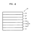
- FIG. 4 illustrates a schematic sectional view of an OLED 20 according to another embodiment.
- the OLED 20 may include a substrate 21, a first electrode 25, a carbonaceous material-containing layer 26, an organic layer 27, and a second electrode 29.
- the second electrode 25 may include an A1-based reflective layer 25a including nickel (Ni) and a first element, a transparent conductive layer 25b, and a second element-containing zinc oxide layer 25c, which are disposed in this order on the substrate 21.
- the substrate 21, the carbonaceous material-containing layer 26, the organic layer 27, the second electrode 29, the A1-based reflective layer 25a including Ni and the first element, and the transparent conductive layer 25b may be the same as described above with reference to FIG. 1 , and thus repeated detailed descriptions thereof are omitted.
- the first electrode 25 may further include the second element-containing zinc oxide layer 25c, in contrast to the OLED 10 in FIG. 1 .
- the second element-containing zinc oxide layer 25c may lower a hole injection barrier by increasing the work function of the first electrode 25. Thus, holes may be easily injected into the organic layer 27 from the first electrode 25.
- the second element in the second element-containing zinc oxide layer 25c may include at least one of aluminum (A1), indium (In), gallium (Ga), germanium (Ge), gadolinium (Gd), zirconium (Zr), molybdenum (Mo), and nickel (Ni).
- the second element may include aluminum (A1).
- the second element may be aluminum (A1).
- the second element may be included in the second element-containing zinc oxide layer 25c in an amount of about 0.5 to about 10 parts by weight, based on 100 parts by weight of the second element-containing zinc oxide layer 25c.
- Maintaining the amount of the second element in the second element-containing zinc oxide layer 25c at about 0.5 to about 10 parts by weight may help ensure that the second element-containing zinc oxide layer 25c has excellent hole transporting ability without a substantial increase in electrical resistance or a substantial reduction in transmittance of visible light.
- the second element may be included in an amount of about 0.5 to about 5 parts by weight, based on 100 parts by weight of the second element-containing zinc oxide layer 25c.
- the second element-containing zinc oxide layer 25c may have a thickness of about 1 ⁇ to about 800 ⁇ , e.g., about 10 ⁇ to 500 ⁇ . Maintaining the thickness of the second element-containing zinc oxide layer 25c at about 1 ⁇ to about 800 ⁇ may help ensure that excellent efficiency and power consumption characteristics are attained with a substantial reduction in driving voltage.
- any of the OLEDs 10 and 20 may further include a metal layer between the A1-based reflective layer 5a (25a) and the substrate 1 (21).
- the metal layer may function as a barrier layer that blocks diffusion of A1 from the A1-based reflective layer 5a (25a) into the substrate 1 (21).
- the metal layer may include at least one of molybdenum (Mo), tungsten (W), titanium (Ti), palladium (Pd), platinum (Pt), and gold (Au).
- the metal layer may include a titanium (Ti) layer.
- the metal layer may have a thickness of about 20 nm to about 200 nm, e.g., about 50 nm to about 100 nm. Maintaining the thickness of the metal layer at about 20 nm to about 200 nm may help ensure that diffusion of aluminum (A1) is effectively prevented.
- the thickness of the metal layer is not limited thereto.
- a 15 ⁇ /cm 2 (1200 ⁇ ) ITO glass substrate (from Coming Co.) was cut to a size of 50 mm x 50 mm x 0.7 mm, ultrasonically washed with isopropyl alcohol for 5 minutes and then with pure water for 5 minutes, and washed again with UV ozone for 30 minutes. Then, m-MTDATA was vacuum-deposited on the ITO layer to form a HIL having a thickness of 700 ⁇ , and then Compound 5 above was vacuum-deposited on the HIL to form a HTL having a thickness of 700 ⁇ .
- An OLED was manufactured in the same manner as in Comparative Example 1, except that a glass substrate on which an A1NiLa layer having a thickness of 5000 ⁇ (containing 2 wt% of Ni and 0.3 wt% of La) and a 70 ⁇ thick ITO layer as a transparent conductive layer were sequentially disposed in this order, was used, instead of the ITO glass substrate, and C 60 was vacuum-deposited on the ITO layer to a thickness of 3 ⁇ to form a carbonaceous material-containing layer before the HIL was formed.
- An OLED was manufactured in the same manner as in Example 1, except that C 60 was deposited to a thickness of 5 ⁇ .
- An OLED was manufactured in the same manner as in Example 1, except that C 60 was deposited to a thickness of 10 ⁇ and no HIL was formed.
- An OLED was manufactured in the same manner as in Example 1, except that C 60 was deposited to a thickness of 30 ⁇ and no HIL was formed.
- an OLED according to an embodiment may have excellent efficiency and power efficiency characteristics.
Landscapes
- Physics & Mathematics (AREA)
- Optics & Photonics (AREA)
- Electroluminescent Light Sources (AREA)
Applications Claiming Priority (1)
| Application Number | Priority Date | Filing Date | Title |
|---|---|---|---|
| KR1020090096820A KR20110039810A (ko) | 2009-10-12 | 2009-10-12 | 유기 발광 소자 |
Publications (3)
| Publication Number | Publication Date |
|---|---|
| EP2309566A2 EP2309566A2 (en) | 2011-04-13 |
| EP2309566A3 EP2309566A3 (en) | 2011-10-19 |
| EP2309566B1 true EP2309566B1 (en) | 2013-03-20 |
Family
ID=43401402
Family Applications (1)
| Application Number | Title | Priority Date | Filing Date |
|---|---|---|---|
| EP10187087A Active EP2309566B1 (en) | 2009-10-12 | 2010-10-11 | Organic light-emitting device |
Country Status (5)
| Country | Link |
|---|---|
| US (1) | US8610346B2 (enExample) |
| EP (1) | EP2309566B1 (enExample) |
| JP (1) | JP2011082173A (enExample) |
| KR (1) | KR20110039810A (enExample) |
| CN (1) | CN102044633B (enExample) |
Families Citing this family (6)
| Publication number | Priority date | Publication date | Assignee | Title |
|---|---|---|---|---|
| KR101156428B1 (ko) * | 2009-06-01 | 2012-06-18 | 삼성모바일디스플레이주식회사 | 유기 발광 소자 |
| KR101097316B1 (ko) * | 2009-10-12 | 2011-12-23 | 삼성모바일디스플레이주식회사 | 유기 발광 소자 |
| JP2011165653A (ja) * | 2010-01-14 | 2011-08-25 | Canon Inc | 有機el素子およびそれを用いた発光装置 |
| KR101917752B1 (ko) * | 2011-05-11 | 2018-11-13 | 가부시키가이샤 한도오따이 에네루기 켄큐쇼 | 발광 소자, 발광 모듈, 발광 패널, 발광 장치 |
| WO2013008765A1 (en) * | 2011-07-08 | 2013-01-17 | Semiconductor Energy Laboratory Co., Ltd. | Light-emitting module, light-emitting device, and method for manufacturing the light-emitting module |
| TWI506835B (zh) * | 2012-07-10 | 2015-11-01 | Innocom Tech Shenzhen Co Ltd | 有機發光二極體、包含其之顯示面板及顯示裝置 |
Citations (1)
| Publication number | Priority date | Publication date | Assignee | Title |
|---|---|---|---|---|
| EP2259362A1 (en) * | 2009-06-01 | 2010-12-08 | Samsung Mobile Display Co., Ltd. | Organic light emitting diode |
Family Cites Families (27)
| Publication number | Priority date | Publication date | Assignee | Title |
|---|---|---|---|---|
| EP0578046B1 (en) * | 1992-07-10 | 1996-11-06 | Asahi Glass Company Ltd. | Transparent conductive film, and target and material for vapor deposition to be used for its production |
| JP3530314B2 (ja) * | 1996-07-25 | 2004-05-24 | 三洋電機株式会社 | 有機エレクトロルミネッセンス素子の製造方法 |
| US6501217B2 (en) * | 1998-02-02 | 2002-12-31 | International Business Machines Corporation | Anode modification for organic light emitting diodes |
| JP2001176673A (ja) * | 1999-12-14 | 2001-06-29 | Tdk Corp | 有機el素子 |
| KR100781620B1 (ko) * | 2001-12-21 | 2007-12-07 | 인터내셔널 비지네스 머신즈 코포레이션 | 전계 발광 장치 및 전계 발광 장치의 형성 방법 |
| JP4241057B2 (ja) * | 2003-01-20 | 2009-03-18 | シャープ株式会社 | 酸化物半導体発光素子およびその製造方法 |
| US7101630B2 (en) * | 2003-07-10 | 2006-09-05 | Kawamura Institute Of Chemical Research | Diarylamino group-containing copolymer, organic electroluminescent device, and method of producing hole transport layer for organic electroluminescent device |
| TW200515836A (en) * | 2003-10-22 | 2005-05-01 | Hannstar Display Corp | Organic electroluminescent element |
| KR100573137B1 (ko) | 2004-04-02 | 2006-04-24 | 삼성에스디아이 주식회사 | 플루오렌계 화합물 및 이를 이용한 유기 전계 발광 소자 |
| KR100590269B1 (ko) * | 2004-05-10 | 2006-06-19 | 삼성에스디아이 주식회사 | 유기 전계 발광 표시 장치 및 그의 제조 방법 |
| EP1653529B1 (en) * | 2004-10-11 | 2007-11-21 | Samsung SDI Co., Ltd. | Organic electroluminescent device and method of manufacturing the same |
| KR100637178B1 (ko) | 2004-10-11 | 2006-10-20 | 삼성에스디아이 주식회사 | 유기 전계 발광 소자 |
| US7358538B2 (en) * | 2004-10-28 | 2008-04-15 | Zheng-Hong Lu | Organic light-emitting devices with multiple hole injection layers containing fullerene |
| US7960037B2 (en) * | 2004-12-03 | 2011-06-14 | The Regents Of The University Of California | Carbon nanotube polymer composition and devices |
| KR100712290B1 (ko) * | 2005-04-12 | 2007-04-27 | 삼성에스디아이 주식회사 | 유기전계발광소자 |
| KR100786291B1 (ko) | 2005-10-24 | 2007-12-18 | 삼성에스디아이 주식회사 | 전면발광형 유기전계발광소자 |
| JP2007142022A (ja) * | 2005-11-16 | 2007-06-07 | Seiko Epson Corp | 金属配線とその製造方法、薄膜トランジスタ、電気光学装置、及び電子機器 |
| KR100741104B1 (ko) | 2005-12-30 | 2007-07-20 | 삼성에스디아이 주식회사 | 유기 발광 소자 |
| US7960040B2 (en) * | 2006-02-28 | 2011-06-14 | Fujifilm Corporation | Organic electroluminescence device |
| JP5060904B2 (ja) * | 2006-10-13 | 2012-10-31 | 株式会社神戸製鋼所 | 反射電極および表示デバイス |
| JP4377906B2 (ja) | 2006-11-20 | 2009-12-02 | 株式会社コベルコ科研 | Al−Ni−La系Al基合金スパッタリングターゲット、およびその製造方法 |
| JP2009008770A (ja) | 2007-06-26 | 2009-01-15 | Kobe Steel Ltd | 積層構造およびその製造方法 |
| JP2009052351A (ja) | 2007-08-28 | 2009-03-12 | Panasonic Electric Works Co Ltd | ヘアキャッチャー |
| JP2009099636A (ja) * | 2007-10-15 | 2009-05-07 | Hitachi Displays Ltd | 表示装置および表示装置の製造方法 |
| JP4611417B2 (ja) * | 2007-12-26 | 2011-01-12 | 株式会社神戸製鋼所 | 反射電極、表示デバイス、および表示デバイスの製造方法 |
| KR100922756B1 (ko) | 2008-02-13 | 2009-10-21 | 삼성모바일디스플레이주식회사 | 전극, 이의 제조 방법, 이를 구비한 전자 소자 |
| JP2008263248A (ja) * | 2008-08-07 | 2008-10-30 | Sumitomo Electric Ind Ltd | 半導体発光素子搭載部材およびその製造方法 |
-
2009
- 2009-10-12 KR KR1020090096820A patent/KR20110039810A/ko not_active Ceased
-
2010
- 2010-10-08 JP JP2010229116A patent/JP2011082173A/ja active Pending
- 2010-10-11 EP EP10187087A patent/EP2309566B1/en active Active
- 2010-10-11 CN CN201010506954.1A patent/CN102044633B/zh active Active
- 2010-10-12 US US12/902,301 patent/US8610346B2/en active Active
Patent Citations (1)
| Publication number | Priority date | Publication date | Assignee | Title |
|---|---|---|---|---|
| EP2259362A1 (en) * | 2009-06-01 | 2010-12-08 | Samsung Mobile Display Co., Ltd. | Organic light emitting diode |
Also Published As
| Publication number | Publication date |
|---|---|
| KR20110039810A (ko) | 2011-04-20 |
| EP2309566A3 (en) | 2011-10-19 |
| CN102044633B (zh) | 2015-01-07 |
| JP2011082173A (ja) | 2011-04-21 |
| US8610346B2 (en) | 2013-12-17 |
| CN102044633A (zh) | 2011-05-04 |
| EP2309566A2 (en) | 2011-04-13 |
| US20110084600A1 (en) | 2011-04-14 |
Similar Documents
| Publication | Publication Date | Title |
|---|---|---|
| EP2309565B1 (en) | Organic light-emitting device | |
| EP2365555B1 (en) | Organic light-emitting device and method of manufacturing the same | |
| US8742402B2 (en) | Organic light-emitting device having a cyano compound | |
| EP2012375B1 (en) | Organic light emitting device | |
| EP2372807B1 (en) | Organic light-emitting device | |
| EP2309566B1 (en) | Organic light-emitting device | |
| US20240107793A1 (en) | Sheet resistance component | |
| EP2259362B1 (en) | Organic light emitting diode | |
| KR20140101226A (ko) | 유기 발광 소자 | |
| JP2011223001A (ja) | 有機発光装置及びその製造方法 | |
| KR101213500B1 (ko) | 유기 발광 소자 | |
| US20240292655A1 (en) | Sheet resistance component |
Legal Events
| Date | Code | Title | Description |
|---|---|---|---|
| PUAI | Public reference made under article 153(3) epc to a published international application that has entered the european phase |
Free format text: ORIGINAL CODE: 0009012 |
|
| AK | Designated contracting states |
Kind code of ref document: A2 Designated state(s): AL AT BE BG CH CY CZ DE DK EE ES FI FR GB GR HR HU IE IS IT LI LT LU LV MC MK MT NL NO PL PT RO RS SE SI SK SM TR |
|
| AX | Request for extension of the european patent |
Extension state: BA ME |
|
| PUAL | Search report despatched |
Free format text: ORIGINAL CODE: 0009013 |
|
| AK | Designated contracting states |
Kind code of ref document: A3 Designated state(s): AL AT BE BG CH CY CZ DE DK EE ES FI FR GB GR HR HU IE IS IT LI LT LU LV MC MK MT NL NO PL PT RO RS SE SI SK SM TR |
|
| AX | Request for extension of the european patent |
Extension state: BA ME |
|
| RIC1 | Information provided on ipc code assigned before grant |
Ipc: H01L 51/52 20060101AFI20110912BHEP |
|
| 17P | Request for examination filed |
Effective date: 20120418 |
|
| 17Q | First examination report despatched |
Effective date: 20120706 |
|
| RAP1 | Party data changed (applicant data changed or rights of an application transferred) |
Owner name: SAMSUNG DISPLAY CO., LTD. |
|
| GRAP | Despatch of communication of intention to grant a patent |
Free format text: ORIGINAL CODE: EPIDOSNIGR1 |
|
| GRAS | Grant fee paid |
Free format text: ORIGINAL CODE: EPIDOSNIGR3 |
|
| GRAA | (expected) grant |
Free format text: ORIGINAL CODE: 0009210 |
|
| AK | Designated contracting states |
Kind code of ref document: B1 Designated state(s): AL AT BE BG CH CY CZ DE DK EE ES FI FR GB GR HR HU IE IS IT LI LT LU LV MC MK MT NL NO PL PT RO RS SE SI SK SM TR |
|
| REG | Reference to a national code |
Ref country code: GB Ref legal event code: FG4D |
|
| REG | Reference to a national code |
Ref country code: CH Ref legal event code: EP |
|
| REG | Reference to a national code |
Ref country code: IE Ref legal event code: FG4D |
|
| REG | Reference to a national code |
Ref country code: AT Ref legal event code: REF Ref document number: 602552 Country of ref document: AT Kind code of ref document: T Effective date: 20130415 |
|
| REG | Reference to a national code |
Ref country code: DE Ref legal event code: R096 Ref document number: 602010005559 Country of ref document: DE Effective date: 20130516 |
|
| PG25 | Lapsed in a contracting state [announced via postgrant information from national office to epo] |
Ref country code: SE Free format text: LAPSE BECAUSE OF FAILURE TO SUBMIT A TRANSLATION OF THE DESCRIPTION OR TO PAY THE FEE WITHIN THE PRESCRIBED TIME-LIMIT Effective date: 20130320 Ref country code: BG Free format text: LAPSE BECAUSE OF FAILURE TO SUBMIT A TRANSLATION OF THE DESCRIPTION OR TO PAY THE FEE WITHIN THE PRESCRIBED TIME-LIMIT Effective date: 20130620 Ref country code: LT Free format text: LAPSE BECAUSE OF FAILURE TO SUBMIT A TRANSLATION OF THE DESCRIPTION OR TO PAY THE FEE WITHIN THE PRESCRIBED TIME-LIMIT Effective date: 20130320 Ref country code: NO Free format text: LAPSE BECAUSE OF FAILURE TO SUBMIT A TRANSLATION OF THE DESCRIPTION OR TO PAY THE FEE WITHIN THE PRESCRIBED TIME-LIMIT Effective date: 20130620 Ref country code: ES Free format text: LAPSE BECAUSE OF FAILURE TO SUBMIT A TRANSLATION OF THE DESCRIPTION OR TO PAY THE FEE WITHIN THE PRESCRIBED TIME-LIMIT Effective date: 20130701 |
|
| REG | Reference to a national code |
Ref country code: AT Ref legal event code: MK05 Ref document number: 602552 Country of ref document: AT Kind code of ref document: T Effective date: 20130320 |
|
| REG | Reference to a national code |
Ref country code: LT Ref legal event code: MG4D |
|
| PG25 | Lapsed in a contracting state [announced via postgrant information from national office to epo] |
Ref country code: LV Free format text: LAPSE BECAUSE OF FAILURE TO SUBMIT A TRANSLATION OF THE DESCRIPTION OR TO PAY THE FEE WITHIN THE PRESCRIBED TIME-LIMIT Effective date: 20130320 Ref country code: FI Free format text: LAPSE BECAUSE OF FAILURE TO SUBMIT A TRANSLATION OF THE DESCRIPTION OR TO PAY THE FEE WITHIN THE PRESCRIBED TIME-LIMIT Effective date: 20130320 Ref country code: SI Free format text: LAPSE BECAUSE OF FAILURE TO SUBMIT A TRANSLATION OF THE DESCRIPTION OR TO PAY THE FEE WITHIN THE PRESCRIBED TIME-LIMIT Effective date: 20130320 Ref country code: GR Free format text: LAPSE BECAUSE OF FAILURE TO SUBMIT A TRANSLATION OF THE DESCRIPTION OR TO PAY THE FEE WITHIN THE PRESCRIBED TIME-LIMIT Effective date: 20130621 |
|
| REG | Reference to a national code |
Ref country code: NL Ref legal event code: VDEP Effective date: 20130320 |
|
| PG25 | Lapsed in a contracting state [announced via postgrant information from national office to epo] |
Ref country code: BE Free format text: LAPSE BECAUSE OF FAILURE TO SUBMIT A TRANSLATION OF THE DESCRIPTION OR TO PAY THE FEE WITHIN THE PRESCRIBED TIME-LIMIT Effective date: 20130320 Ref country code: HR Free format text: LAPSE BECAUSE OF FAILURE TO SUBMIT A TRANSLATION OF THE DESCRIPTION OR TO PAY THE FEE WITHIN THE PRESCRIBED TIME-LIMIT Effective date: 20130320 Ref country code: RS Free format text: LAPSE BECAUSE OF FAILURE TO SUBMIT A TRANSLATION OF THE DESCRIPTION OR TO PAY THE FEE WITHIN THE PRESCRIBED TIME-LIMIT Effective date: 20130320 |
|
| PG25 | Lapsed in a contracting state [announced via postgrant information from national office to epo] |
Ref country code: NL Free format text: LAPSE BECAUSE OF FAILURE TO SUBMIT A TRANSLATION OF THE DESCRIPTION OR TO PAY THE FEE WITHIN THE PRESCRIBED TIME-LIMIT Effective date: 20130320 Ref country code: CZ Free format text: LAPSE BECAUSE OF FAILURE TO SUBMIT A TRANSLATION OF THE DESCRIPTION OR TO PAY THE FEE WITHIN THE PRESCRIBED TIME-LIMIT Effective date: 20130320 Ref country code: RO Free format text: LAPSE BECAUSE OF FAILURE TO SUBMIT A TRANSLATION OF THE DESCRIPTION OR TO PAY THE FEE WITHIN THE PRESCRIBED TIME-LIMIT Effective date: 20130320 Ref country code: IS Free format text: LAPSE BECAUSE OF FAILURE TO SUBMIT A TRANSLATION OF THE DESCRIPTION OR TO PAY THE FEE WITHIN THE PRESCRIBED TIME-LIMIT Effective date: 20130720 Ref country code: PT Free format text: LAPSE BECAUSE OF FAILURE TO SUBMIT A TRANSLATION OF THE DESCRIPTION OR TO PAY THE FEE WITHIN THE PRESCRIBED TIME-LIMIT Effective date: 20130722 Ref country code: SK Free format text: LAPSE BECAUSE OF FAILURE TO SUBMIT A TRANSLATION OF THE DESCRIPTION OR TO PAY THE FEE WITHIN THE PRESCRIBED TIME-LIMIT Effective date: 20130320 Ref country code: AT Free format text: LAPSE BECAUSE OF FAILURE TO SUBMIT A TRANSLATION OF THE DESCRIPTION OR TO PAY THE FEE WITHIN THE PRESCRIBED TIME-LIMIT Effective date: 20130320 Ref country code: EE Free format text: LAPSE BECAUSE OF FAILURE TO SUBMIT A TRANSLATION OF THE DESCRIPTION OR TO PAY THE FEE WITHIN THE PRESCRIBED TIME-LIMIT Effective date: 20130320 |
|
| PG25 | Lapsed in a contracting state [announced via postgrant information from national office to epo] |
Ref country code: PL Free format text: LAPSE BECAUSE OF FAILURE TO SUBMIT A TRANSLATION OF THE DESCRIPTION OR TO PAY THE FEE WITHIN THE PRESCRIBED TIME-LIMIT Effective date: 20130320 Ref country code: CY Free format text: LAPSE BECAUSE OF FAILURE TO SUBMIT A TRANSLATION OF THE DESCRIPTION OR TO PAY THE FEE WITHIN THE PRESCRIBED TIME-LIMIT Effective date: 20130320 |
|
| PLBE | No opposition filed within time limit |
Free format text: ORIGINAL CODE: 0009261 |
|
| STAA | Information on the status of an ep patent application or granted ep patent |
Free format text: STATUS: NO OPPOSITION FILED WITHIN TIME LIMIT |
|
| PG25 | Lapsed in a contracting state [announced via postgrant information from national office to epo] |
Ref country code: DK Free format text: LAPSE BECAUSE OF FAILURE TO SUBMIT A TRANSLATION OF THE DESCRIPTION OR TO PAY THE FEE WITHIN THE PRESCRIBED TIME-LIMIT Effective date: 20130320 |
|
| 26N | No opposition filed |
Effective date: 20140102 |
|
| PG25 | Lapsed in a contracting state [announced via postgrant information from national office to epo] |
Ref country code: IT Free format text: LAPSE BECAUSE OF FAILURE TO SUBMIT A TRANSLATION OF THE DESCRIPTION OR TO PAY THE FEE WITHIN THE PRESCRIBED TIME-LIMIT Effective date: 20130320 |
|
| REG | Reference to a national code |
Ref country code: DE Ref legal event code: R097 Ref document number: 602010005559 Country of ref document: DE Effective date: 20140102 |
|
| PG25 | Lapsed in a contracting state [announced via postgrant information from national office to epo] |
Ref country code: MC Free format text: LAPSE BECAUSE OF FAILURE TO SUBMIT A TRANSLATION OF THE DESCRIPTION OR TO PAY THE FEE WITHIN THE PRESCRIBED TIME-LIMIT Effective date: 20130320 |
|
| REG | Reference to a national code |
Ref country code: IE Ref legal event code: MM4A |
|
| PG25 | Lapsed in a contracting state [announced via postgrant information from national office to epo] |
Ref country code: IE Free format text: LAPSE BECAUSE OF NON-PAYMENT OF DUE FEES Effective date: 20131011 |
|
| PG25 | Lapsed in a contracting state [announced via postgrant information from national office to epo] |
Ref country code: SM Free format text: LAPSE BECAUSE OF FAILURE TO SUBMIT A TRANSLATION OF THE DESCRIPTION OR TO PAY THE FEE WITHIN THE PRESCRIBED TIME-LIMIT Effective date: 20130320 |
|
| REG | Reference to a national code |
Ref country code: CH Ref legal event code: PL |
|
| PG25 | Lapsed in a contracting state [announced via postgrant information from national office to epo] |
Ref country code: TR Free format text: LAPSE BECAUSE OF FAILURE TO SUBMIT A TRANSLATION OF THE DESCRIPTION OR TO PAY THE FEE WITHIN THE PRESCRIBED TIME-LIMIT Effective date: 20130320 |
|
| PG25 | Lapsed in a contracting state [announced via postgrant information from national office to epo] |
Ref country code: CH Free format text: LAPSE BECAUSE OF NON-PAYMENT OF DUE FEES Effective date: 20141031 Ref country code: LI Free format text: LAPSE BECAUSE OF NON-PAYMENT OF DUE FEES Effective date: 20141031 Ref country code: LU Free format text: LAPSE BECAUSE OF NON-PAYMENT OF DUE FEES Effective date: 20131011 Ref country code: HU Free format text: LAPSE BECAUSE OF FAILURE TO SUBMIT A TRANSLATION OF THE DESCRIPTION OR TO PAY THE FEE WITHIN THE PRESCRIBED TIME-LIMIT; INVALID AB INITIO Effective date: 20101011 Ref country code: MK Free format text: LAPSE BECAUSE OF FAILURE TO SUBMIT A TRANSLATION OF THE DESCRIPTION OR TO PAY THE FEE WITHIN THE PRESCRIBED TIME-LIMIT Effective date: 20130320 |
|
| PG25 | Lapsed in a contracting state [announced via postgrant information from national office to epo] |
Ref country code: MT Free format text: LAPSE BECAUSE OF FAILURE TO SUBMIT A TRANSLATION OF THE DESCRIPTION OR TO PAY THE FEE WITHIN THE PRESCRIBED TIME-LIMIT Effective date: 20130320 |
|
| REG | Reference to a national code |
Ref country code: FR Ref legal event code: PLFP Year of fee payment: 6 |
|
| REG | Reference to a national code |
Ref country code: FR Ref legal event code: PLFP Year of fee payment: 7 |
|
| REG | Reference to a national code |
Ref country code: FR Ref legal event code: PLFP Year of fee payment: 8 |
|
| REG | Reference to a national code |
Ref country code: FR Ref legal event code: PLFP Year of fee payment: 9 |
|
| PG25 | Lapsed in a contracting state [announced via postgrant information from national office to epo] |
Ref country code: AL Free format text: LAPSE BECAUSE OF FAILURE TO SUBMIT A TRANSLATION OF THE DESCRIPTION OR TO PAY THE FEE WITHIN THE PRESCRIBED TIME-LIMIT Effective date: 20130320 |
|
| REG | Reference to a national code |
Ref country code: DE Ref legal event code: R079 Ref document number: 602010005559 Country of ref document: DE Free format text: PREVIOUS MAIN CLASS: H01L0051520000 Ipc: H10K0050800000 |
|
| P01 | Opt-out of the competence of the unified patent court (upc) registered |
Effective date: 20230515 |
|
| PGFP | Annual fee paid to national office [announced via postgrant information from national office to epo] |
Ref country code: GB Payment date: 20250922 Year of fee payment: 16 |
|
| PGFP | Annual fee paid to national office [announced via postgrant information from national office to epo] |
Ref country code: FR Payment date: 20250925 Year of fee payment: 16 |
|
| PGFP | Annual fee paid to national office [announced via postgrant information from national office to epo] |
Ref country code: DE Payment date: 20250922 Year of fee payment: 16 |