EP2309108B1 - Gas turbine with improved turn down operation - Google Patents
Gas turbine with improved turn down operation Download PDFInfo
- Publication number
- EP2309108B1 EP2309108B1 EP08876707.4A EP08876707A EP2309108B1 EP 2309108 B1 EP2309108 B1 EP 2309108B1 EP 08876707 A EP08876707 A EP 08876707A EP 2309108 B1 EP2309108 B1 EP 2309108B1
- Authority
- EP
- European Patent Office
- Prior art keywords
- section
- cooling air
- gas turbine
- turbine
- air system
- Prior art date
- Legal status (The legal status is an assumption and is not a legal conclusion. Google has not performed a legal analysis and makes no representation as to the accuracy of the status listed.)
- Active
Links
Images


Classifications
-
- F—MECHANICAL ENGINEERING; LIGHTING; HEATING; WEAPONS; BLASTING
- F02—COMBUSTION ENGINES; HOT-GAS OR COMBUSTION-PRODUCT ENGINE PLANTS
- F02C—GAS-TURBINE PLANTS; AIR INTAKES FOR JET-PROPULSION PLANTS; CONTROLLING FUEL SUPPLY IN AIR-BREATHING JET-PROPULSION PLANTS
- F02C9/00—Controlling gas-turbine plants; Controlling fuel supply in air- breathing jet-propulsion plants
- F02C9/16—Control of working fluid flow
- F02C9/18—Control of working fluid flow by bleeding, bypassing or acting on variable working fluid interconnections between turbines or compressors or their stages
-
- F—MECHANICAL ENGINEERING; LIGHTING; HEATING; WEAPONS; BLASTING
- F01—MACHINES OR ENGINES IN GENERAL; ENGINE PLANTS IN GENERAL; STEAM ENGINES
- F01D—NON-POSITIVE DISPLACEMENT MACHINES OR ENGINES, e.g. STEAM TURBINES
- F01D25/00—Component parts, details, or accessories, not provided for in, or of interest apart from, other groups
- F01D25/08—Cooling; Heating; Heat-insulation
- F01D25/12—Cooling
-
- F—MECHANICAL ENGINEERING; LIGHTING; HEATING; WEAPONS; BLASTING
- F02—COMBUSTION ENGINES; HOT-GAS OR COMBUSTION-PRODUCT ENGINE PLANTS
- F02C—GAS-TURBINE PLANTS; AIR INTAKES FOR JET-PROPULSION PLANTS; CONTROLLING FUEL SUPPLY IN AIR-BREATHING JET-PROPULSION PLANTS
- F02C7/00—Features, components parts, details or accessories, not provided for in, or of interest apart form groups F02C1/00 - F02C6/00; Air intakes for jet-propulsion plants
- F02C7/12—Cooling of plants
- F02C7/16—Cooling of plants characterised by cooling medium
- F02C7/18—Cooling of plants characterised by cooling medium the medium being gaseous, e.g. air
- F02C7/185—Cooling means for reducing the temperature of the cooling air or gas
-
- Y—GENERAL TAGGING OF NEW TECHNOLOGICAL DEVELOPMENTS; GENERAL TAGGING OF CROSS-SECTIONAL TECHNOLOGIES SPANNING OVER SEVERAL SECTIONS OF THE IPC; TECHNICAL SUBJECTS COVERED BY FORMER USPC CROSS-REFERENCE ART COLLECTIONS [XRACs] AND DIGESTS
- Y02—TECHNOLOGIES OR APPLICATIONS FOR MITIGATION OR ADAPTATION AGAINST CLIMATE CHANGE
- Y02T—CLIMATE CHANGE MITIGATION TECHNOLOGIES RELATED TO TRANSPORTATION
- Y02T50/00—Aeronautics or air transport
- Y02T50/60—Efficient propulsion technologies, e.g. for aircraft
Definitions
- the present invention relates to a gas turbine, and more specifically relates to a gas turbine enabling turn down operation (operation at part load or operation at low load).
- JP 2007-182883 A A gas turbine disclosed in JP 2007-182883 A is known as an example of a gas turbine enabling turn down operation.
- US 2003/0046938 A1 discloses a gas turbine with two stator cooling air systems respectively connecting the compressor and the turbine for bleeding compressed air from the compressor to the turbine.
- a crossover flowpath is provided for connecting a flowpath with the flowpath through a crossover flowpath including an injector, a control/throttling valve and a sensor.
- the document teaches that the flow characteristics criteria influenced by opening the throttling valve in the crossover flowpath should be based on "ambient conditions” and that "the signal to the valve determining the opening degree of the crossover flowpath is a function of the difference between the sensed flow characteristics and the predetermined flow characteristics, i.e., a function of ambient conditions".
- WO 97/23715 A2 discloses a gas turbine in which a separate cooling air line is provided from different pressure level positions of a compressor to each of plural rotor blade stages.
- US 6,615,574 B1 discloses a gas turbine which is provided with a crossover path for allowing a selective flow between a low pressure line and a mid pressure line connecting a compressor with a turbine stage of the gas turbine.
- JP 2002339708 A discloses a gas turbine in which a backflow prevention valve is provided in a compressed air line from a compressor to a turbine section.
- JP 051711958 A discloses a gas turbine with a plurality of compressed air lines connecting various pressure stages of a compressor with a turbine section and flow amount control valves respectively arranged in such compressed air lines.
- the present invention was made to address such a situation, with an object of providing a gas turbine enabling turn down operation, by which the system and the operation of the gas turbine can be simplified, and also the production cost and the maintenance cost can be reduced.
- the present invention provides a gas turbine as defined in claim 1, claim 2, claim 4 or claim 6.
- the gas turbine according to a first aspect of the present invention is a gas turbine comprising: a compressor section for compressing combustion air; a combustor section for injecting a fuel into high pressure air being sent from this compressor section, to effect combustion so as to generate a high temperature combustion gas; a turbine section which is located at the downstream side of this combustor section, and is driven by the combustion gas coming out from the combustor section; a gas turbine casing which houses the compressor section, the combustor section, and the turbine section therein; a stator cooling air system for leading compressed air that has been extracted from midstream of the compressor section, into stator vanes which constitute the turbine section; and an air bleeding system for extracting compressed air from the exit of the compressor section to the outside of the gas turbine casing, wherein midstream of the stator cooling air system and midstream of the air bleeding system are connected via a connecting path, and midstream of this connecting path is connected with a flow rate control part.
- the turn down operation is enabled by using the already-existing stator cooling air system and air bleeding system. Therefore, the system and the operation of the gas turbine can be simplified, and also the production cost and the maintenance cost can be reduced.
- the flow rate control part for example, a control valve
- the flow rate control part for example, a control valve
- the (high pressure) compressed air that has been extracted from the exit (rear stage) of the compressor section bypasses the combustor section and runs through the stator cooling air system and the stator vanes until it flows in the working fluid path of the turbine section. Therefore, the temperature of the exhaust gas can be lowered.
- the (high pressure) compressed air that has been extracted from the exit (rear stage) of the compressor section bypasses the combustor section and runs through the stator cooling air system and the air bleeding system until it flows in the turbine section. Therefore, upon the turn down operation, the temperature of the turbine section can be lowered while keeping the turbine inlet temperature high, because of which the service life of parts constituting the turbine section such as turbine blades (rotor blades and stator vanes) can be elongated.
- a backflow prevention part is connected to the stator cooling air system at the upstream side of a merge point, where the downstream end of the connecting path is merging.
- the compressed air led to the upstream side of the stator cooling air system via the connecting path and the flow rate control part can be kept from flowing from the merge point toward the compressor section, by the backflow prevention part (for example, a check valve). Therefore, the backflow from the merge point to the compressor section can be reliably prevented.
- the gas turbine according to a second aspect of the present invention is a gas turbine comprising: a compressor section for compressing combustion air; a combustor section for injecting a fuel into high pressure air being sent from this compressor section, to effect combustion so as to generate a high temperature combustion gas; a turbine section which is located at the downstream side of this combustor section, and is driven by the combustion gas coming out from the combustor section; and at least two stator cooling air systems for respectively leading at least two types of compressed air that have been extracted from at least two positions having different pressures of the compressor section, into respective stator vanes which constitute the turbine section, according to the pressure of the extracted compressed air, wherein at least two of the stator cooling air systems are connected via a connecting path.
- the turn down operation is enabled by using the already-existing stator cooling air system. Therefore, the system and the operation of the gas turbine can be simplified, and also the production cost and the maintenance cost can be reduced.
- the compressed air that has been extracted from the compressor section bypasses the combustor section and runs through the stator cooling air system(s) and the stator vanes (for example, fourth stage stator vanes) until it flows in the working fluid path of the turbine section. Therefore, the temperature of the exhaust gas can be lowered.
- the compressed air that has been extracted from the compressor section bypasses the combustor section and runs through the stator cooling air system(s) and the stator vanes (for example, fourth stage stator vanes) until it flows in the turbine section. Therefore, upon the turn down operation, the temperature of the turbine section can be lowered while keeping the turbine inlet temperature high, because of which the service life of parts constituting the turbine section such as turbine blades (rotor blades and stator vanes) can be elongated.
- a backflow prevention part is connected to the stator cooling air system at the upstream side of a merge point, where the downstream end of the connecting path is merging.
- the compressed air led to the midstream of the stator cooling air system via the connecting path can be kept from flowing from the merge point toward the compressor section, by the backflow prevention part (for example, a check valve). Therefore, the backflow from the merge point to the compressor section can be reliably prevented.
- the backflow prevention part for example, a check valve
- the gas turbine according to the second aspect of the present invention preferably comprises: a first stator cooling air system for leading compressed air that has been extracted from a low-pressure stage of the compressor section, into low-pressure stage stator vanes which constitute the turbine section; and a second stator cooling air system for leading compressed air that has been extracted from a high-pressure stage of the compressor section, into high-pressure stage stator vanes which constitute the turbine section, wherein midstream of the first stator cooling air system and midstream of the second stator cooling air system are connected via a connecting path.
- the turn down operation is enabled by using the already-existing stator cooling air system. Therefore, the system and the operation of the gas turbine can be simplified, and also the production cost and the maintenance cost can be reduced.
- the (high pressure) compressed air that has been extracted from the high-pressure stage of the compressor section bypasses the combustor section and runs through the first stator cooling air system and the stator vanes (for example, fourth stage stator vanes) until it flows in the working fluid path of the turbine section. Therefore, the temperature of the exhaust gas can be lowered.
- the (high pressure) compressed air that has been extracted from the high-pressure stage of the compressor section bypasses the combustor section and runs through the first stator cooling air system and the stator vanes (for example, fourth stage stator vanes) until it flows in the turbine section. Therefore, upon the turn down operation, the temperature of the turbine section can be lowered while keeping the turbine inlet temperature high, because of which the service life of parts constituting the turbine section such as turbine blades (rotor blades and stator vanes) can be elongated.
- the gas turbine according to a third aspect of the present invention is a gas turbine comprising: a compressor section for compressing combustion air; a combustor section for injecting a fuel into high pressure air being sent from this compressor section, to effect combustion so as to generate a high temperature combustion gas; a turbine section which is located at the downstream side of this combustor section, and is driven by the combustion gas coming out from the combustor section; a first stator cooling air system for leading compressed air that has been extracted from a low-pressure stage of the compressor section, into low-pressure stage stator vanes which constitute the turbine section; a second stator cooling air system for leading compressed air that has been extracted from a medium-pressure stage of the compressor section, into medium-pressure stage stator vanes which constitute the turbine section; and a third stator cooling air system for leading compressed air that has been extracted from a high-pressure stage of the compressor section, into high-pressure stage stator vanes which constitute the turbine section, wherein midstream of the second stator cooling air system and midstream of the third stat
- the turn down operation is enabled by using the already-existing stator cooling air system. Therefore, the system and the operation of the gas turbine can be simplified, and also the production cost and the maintenance cost can be reduced.
- the (high pressure) compressed air that has been extracted from the high-pressure stage of the compressor section bypasses the combustor section and runs through the second stator cooling air system and the stator vanes (for example, third stage stator vanes) until it flows in the working fluid path of the turbine section. Therefore, the temperature of the exhaust gas can be lowered.
- the (high pressure) compressed air that has been extracted from the high-pressure stage of the compressor section bypasses the combustor section and runs through the second stator cooling air system and the stator vanes (for example, third stage stator vanes) until it flows in the turbine section. Therefore, upon the turn down operation, the temperature of the turbine section can be lowered while keeping the turbine inlet temperature high, because of which the service life of parts constituting the turbine section such as turbine blades (rotor blades and stator vanes) can be elongated.
- the gas turbine is more preferable if a backflow prevention part is connected to the second stator cooling air system at the upstream side of a merge point, where the downstream end of the connecting path is merging.
- the compressed air led to the midstream of the second stator cooling air system via the connecting path can be kept from flowing from the merge point toward the compressor section, by the backflow prevention part (for example, a check valve). Therefore, the backflow from the merge point to the compressor section can be reliably prevented.
- the backflow prevention part for example, a check valve
- the gas turbine according to a fourth aspect of the present invention is a gas turbine comprising: a compressor section for compressing combustion air; a combustor section for injecting a fuel into high pressure air being sent from this compressor section, to effect combustion so as to generate a high temperature combustion gas; a turbine section which is located at the downstream side of this combustor section, and is driven by the combustion gas coming out from the combustor section; and a rotor cooling air system for leading compressed air that has been extracted from the exit of the compressor section, into a rotor which constitutes the turbine section, wherein midstream of the rotor cooling air system is connected with a boost compressor, and a bypass system for bypassing the boost compressor is provided.
- the boost compressor upon the turn down operation, the boost compressor is operated.
- the (high pressure) compressed air that has been extracted from the high-pressure stage of the compressor section bypasses the combustor section and runs through the rotor cooling air system and the rotor blades until it is forcibly (vigorously) led in the working fluid path of the turbine section. Therefore, the temperature of the exhaust gas can be lowered.
- the (high pressure) compressed air that has been extracted from the exit (rear stage) of the compressor section bypasses the combustor section and runs through the rotor cooling air system until it flows in the turbine section. Therefore, upon the turn down operation, the temperature of the turbine section can be lowered while keeping the turbine inlet temperature high, because of which the service life of parts constituting the turbine section such as turbine blades (rotor blades and stator vanes) can be elongated.
- the gas turbine enabling turn down operation of the present invention can offer effects of simplifying the system and the operation of the gas turbine, and reducing the production cost and the maintenance cost.
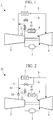
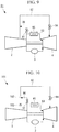
- FIG. 1 is a system diagram of the gas turbine according to this example.
- the gas turbine 1 of this example comprises: a compressor section 2 for compressing combustion air; a combustor section 3 for injecting a fuel into high pressure air being sent from this compressor section 2, to effect combustion so as to generate a high temperature combustion gas; a turbine section 4 which is located at the downstream side of this combustor section 3, and is driven by the combustion gas coming out from the combustor section 3; a gas turbine casing (not shown) which houses the compressor section 2, the combustor section 3, and the turbine section 4 therein; a stator cooling air system 5 for leading (medium pressure) compressed air that has been extracted from midstream (mid stage) of the compressor section 2, into stator vanes (for example, second stage stator vanes) which constitute the turbine section 4; and a rotor cooling air system (air bleeding system)
- stator cooling air system 5 At midstream of the stator cooling air system 5, there is a first cooler 7 which cools down the compressed air passing therethrough connected.
- stator cooling air system 5 is connected with a bypass system 8 which bypasses the first cooler 7 (that is to say, which connects between a part of the stator cooling air system 5 at the upstream side of the first cooler 7 and another part of the stator cooling air system 5 at the downstream side of the first cooler 7).
- bypass system 8 which bypasses the first cooler 7 (that is to say, which connects between a part of the stator cooling air system 5 at the upstream side of the first cooler 7 and another part of the stator cooling air system 5 at the downstream side of the first cooler 7).
- control valve 9 for adjusting the air flow rate of the bypass system 8 connected.
- the upstream end of the connecting pipe 12 may be directly connected to the exit of the compressor section 2 for use as the air bleeding system.
- the turn down operation is enabled by using the stator cooling air system 5 which is already existing therein (as an essential component). Therefore, the system and the operation of the gas turbine can be simplified, and also the production cost and the maintenance cost can be reduced.
- the system and the operation of the gas turbine can be further simplified, and the production cost and the maintenance cost can be further reduced.
- the second control valve 13 is opened.
- the (high pressure) compressed air that has been extracted from the exit (rear stage) of the compressor section 2 bypasses the combustor section 3 and runs through the stator cooling air system 5 and the.stator vanes (not shown) until it flows in the working fluid path of the turbine section 4. Therefore, the temperature of the exhaust gas can be lowered.
- the (high pressure) compressed air that has been extracted from the exit (rear stage) of the compressor section 2 bypasses the combustor section 3 and runs through the stator cooling air system 5 until it flows in the turbine section 4.
- the temperature of the turbine section 4 can be lowered while keeping the turbine inlet temperature high, because of which the service life of parts constituting the turbine section 4 such as turbine blades (rotor blades and stator vanes) can be elongated.
- the second control valve 13 is closed.
- the (high pressure) compressed air that has been extracted from the exit (rear stage) of the compressor section 2 runs through the rotor cooling air system 6 until it is all let in the turbine section 4.
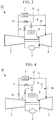
- FIG. 2 is a system diagram of the gas turbine according to this embodiment.
- the gas turbine 21 of this embodiment differs from the gas turbine of the aforementioned first example, in the point where a check valve (backflow prevention part) 23 is connected to the stator cooling air system 5 at the upstream side of a merge point 22, where the downstream end of the connecting pipe 12 is merging.
- the other components are the same as those of the aforementioned first example, and thus these components are not described herein.
- the compressed air led to the upstream side of the stator cooling air system 5 via the connecting pipe 12 and the second control valve 13 can be kept from flowing from the merge point 22 toward the compressor section 2, by the check valve 23. Therefore, the backflow from the merge point 22 to the compressor section 2 can be reliably prevented.
- the other operations and effects are the same as those of the aforementioned first example, and thus are not described herein.
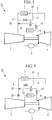
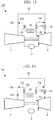
- FIG. 3 is a system diagram of the gas turbine according to this example.
- the gas turbine 31 of this example differs from the gas turbine of the aforementioned first example, in the point where the downstream end of the connecting pipe 12 is connected to the stator cooling air system 5 at the downstream side of a merge point 32, where the downstream end of the bypass system 8 is merging.
- the other components are the same as those of the aforementioned first example, and thus these components are not described herein.
- the turn down operation is enabled by using the stator cooling air system 5 which is already existing therein (as an essential component). Therefore, the system and the operation of the gas turbine can be simplified, and also the production cost and the maintenance cost can be reduced.
- the second control valve 13 is opened.
- the (high pressure) compressed air that has been extracted from the exit (rear stage) of the compressor section 2 bypasses the combustor section 3 and runs through the stator cooling air system 5 and the stator vanes (not shown) until it flows in the working fluid path of the turbine section 4. Therefore, the temperature of the exhaust gas can be lowered.
- the (high pressure) compressed air that has been extracted from the exit (rear stage) of the compressor section 2 bypasses the combustor section 3 and runs through the stator cooling air system 5 until it flows in the turbine section 4.
- the temperature of the turbine section 4 can be lowered while keeping the turbine inlet temperature high, because of which the service life of parts constituting the turbine section 4 such as turbine blades (rotor blades and stator vanes) can be elongated.
- the second control valve 13 is closed.
- the (high pressure) compressed air that has been extracted from the exit (rear stage) of the compressor section 2 runs through the rotor cooling air system 6 until it is all let in the turbine section 4.
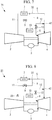
- FIG. 4 is a system diagram of the gas turbine according to this embodiment.
- the gas turbine 41 of this embodiment differs from the gas turbine of the aforementioned second example, in the point where the check valve 23 is connected to the stator cooling air system 5 at the upstream side of the branch point 11, where the upstream end of the bypass system 8 is branching.
- the other components are the same as those of the aforementioned second example, and thus these components are not described herein.
- the compressed air led to the downstream side of the stator cooling air system 5 via the connecting pipe 12 and the second control valve 13 can be kept from flowing from a merge point 42, where the downstream end of the connecting pipe 12 is merging, toward the compressor section 2, by the check valve 23. Therefore, the backflow from the merge point 42 to the compressor section 2 can be reliably prevented.
- the other operations and effects are the same as those of the aforementioned second example, and thus are not described herein.
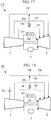
- FIG. 5 is a system diagram of the gas turbine according to this example.
- the gas turbine 51 of this example differs from the gas turbine of the aforementioned first example, in the point where the upstream end of the connecting pipe 12 is connected to the rotor cooling air system 6 at the downstream side of the second cooler 10.
- the other components are the same as those of the aforementioned first example, and thus these components are not described herein.
- the turn down operation is enabled by using the stator cooling air system 5 and the rotor cooling air system 6 which are already existing therein (as essential components). Therefore, the system and the operation of the gas turbine can be simplified, and also the production cost and the maintenance cost can be reduced. Moreover, upon the turn down operation, the second control valve 13 is opened. As a result, the (high pressure) compressed air that has been extracted from the exit (rear stage) of the compressor section 2 bypasses the combustor section 3 and runs through the stator cooling air system 5 and the stator vanes (not shown) until it flows in the working fluid path of the turbine section 4. Therefore, the temperature of the exhaust gas can be lowered.
- the (high pressure) compressed air that has been extracted from the exit (rear stage) of the compressor section 2 bypasses the combustor section 3 and runs through the stator cooling air system 5 and the rotor cooling air system 6 until it flows in the turbine section 4. Therefore, upon the turn down operation, the temperature of the turbine section 4 can be lowered while keeping the turbine inlet temperature high, because of which the service life of parts constituting the turbine section 4 such as turbine blades (rotor blades and stator vanes) can be elongated.
- the second control valve 13 is closed.
- the (high pressure) compressed air that has been extracted from the exit (rear stage) of the compressor section 2 runs through the rotor cooling air system 6 until it is all let in the turbine section 4.
- FIG. 6 is a system diagram of the gas turbine according to this embodiment.
- the gas turbine 61 of this embodiment differs from the gas turbine of the aforementioned third example, in the point where the check valve 23 is connected to the stator cooling air system 5 at the upstream side of the merge point 22, where the downstream end of the connecting pipe 12 is merging.
- the other components are the same as those of the aforementioned third example, and thus these components are not described herein.
- the compressed air led to the upstream side of the stator cooling air system 5 via the connecting pipe 12 and the second control valve 13 can be kept from flowing from the merge point 22 toward the compressor section 2, by the check valve 23. Therefore, the backflow from the merge point 22 to the compressor section 2 can be reliably prevented.
- the other operations and effects are the same as those of the aforementioned third example, and thus are not described herein.
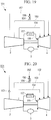
- FIG. 7 is a system diagram of the gas turbine according to this example.
- the gas turbine 71 of this example differs from the gas turbine of the aforementioned third example, in the point where the downstream end of the connecting pipe 12 is connected to the stator cooling air system 5 at the downstream side of the merge point 32, where the downstream end of the bypass system 8 is merging.
- the other components are the same as those of the aforementioned third example, and thus these components are not described herein.
- the turn down operation is enabled by using the stator cooling air system 5 and the rotor cooling air system 6 which are already existing therein (as essential components). Therefore, the system and the operation of the gas turbine can be simplified, and also the production cost and the maintenance cost can be reduced.
- the second control valve 13 is opened.
- the (high pressure) compressed air that has been extracted from the exit (rear stage) of the compressor section 2 bypasses the combustor section 3 and runs through the stator cooling air system 5 and the stator vanes (not shown) until it flows in the working fluid path of the turbine section 4. Therefore, the temperature of the exhaust gas can be lowered.
- the (high pressure) compressed air that has been extracted from the exit (rear stage) of the compressor section 2 bypasses the combustor section 3 and runs through the stator cooling air system 5 and the rotor cooling air system 6 until it flows in the turbine section 4. Therefore, upon the turn down operation, the temperature of the turbine section 4 can be lowered while keeping the turbine inlet temperature high, because of which the service life of parts constituting the turbine section 4 such as turbine blades (rotor blades and stator vanes) can be elongated.
- the second control valve 13 is closed.
- the (high pressure) compressed air that has been extracted from the exit (rear stage) of the compressor section 2 runs through the rotor cooling air system 6 until it is all let in the turbine section 4.
- FIG. 8 is a system diagram of the gas turbine according to this embodiment.
- the gas turbine 81 of this embodiment differs from the gas turbine of the aforementioned fourth example, in the point where the check valve (backflow prevention part) 23 is connected to the stator cooling air system 5 at the upstream side of the branch point 11, where the upstream end of the bypass system 8 is branching.
- the other components are the same as those of the aforementioned fourth example, and thus these components are not described herein.
- the compressed air led to the downstream side of the stator cooling air system 5 via the connecting pipe 12 and the second control valve 13 can be kept from flowing from the merge point 42, where the downstream end of the connecting pipe 12 is merging, toward the compressor section 2,:by the check valve 23. Therefore, the backflow from the merge point 42 to the compressor section 2 can be reliably prevented.
- the other operations and effects are the same as those of the aforementioned fourth example, and thus are not described herein.
- FIG. 9 is a system diagram of the gas turbine according to this example.
- the gas turbine 91 of this example comprises: a compressor section 2 for compressing combustion air; a combustor section 3 for injecting a fuel into high pressure air being sent from this compressor section 2, to effect combustion so as to generate a high temperature combustion gas; a turbine section 4 which is located at the downstream side of this combustor section 3, and is driven by the combustion gas coming out from the combustor section 3; a gas turbine casing (not shown) which houses the compressor section 2, the combustor section 3, and the turbine section 4 therein; a stator cooling air system 92 for leading (medium pressure) compressed air that has been extracted from midstream (mid stage) of the compressor section 2, into stator vanes (for example, second stage stator vanes) which constitute the turbine section 4; and a rotor cooling air system (air bleeding system
- first control valve 94 At midstream of the stator cooling air system 92, there is a first control valve 94 connected, the opening degree of which can be adjusted by a controller (not shown). Meanwhile, at midstream of the rotor cooling air system 93, there is a cooler 95 which cools down the compressed air passing therethrough connected. In addition, the rotor cooling air system 93 at the upstream side of the cooler 95 and the stator cooling air system 92 at the upstream side of the first control valve 94 are connected by a connecting pipe (connecting path) 96. At midstream of this connecting pipe 96, there is a second control valve (flow rate control part) 97 connected, the opening degree of which can be adjusted by a controller (not shown).
- the upstream end of the connecting pipe 96 may be directly connected to the exit of the compressor section 2 for use as the air bleeding system.
- the turn down operation is enabled by using the stator cooling air system 92 which is already existing therein (as an essential component). Therefore, the system and the operation of the gas turbine can be simplified, and also the production cost and the maintenance cost can be reduced. Moreover, upon the turn down operation, the second control valve 97 is opened. As a result, the (high pressure) compressed air that has been extracted from the exit (rear stage) of the compressor section 2 bypasses the combustor section 3 and runs through the stator cooling air system 92 and the stator vanes (not shown) until it flows in the working fluid path of the turbine section 4. Therefore, the temperature of the exhaust gas can be lowered.
- the (high pressure) compressed air that has been extracted from the exit (rear stage) of the compressor section 2 bypasses the combustor section 3 and runs through the stator cooling air system 92 and the rotor cooling air system 93 until it flows in the turbine section 4 Therefore, upon the turn down operation, the temperature of the turbine section 4 can be lowered while keeping the turbine inlet temperature high, because of which the service life of parts constituting the turbine section 4 such as turbine blades (rotor blades and stator vanes) can be elongated.
- the second control valve 97 is closed.
- the (high pressure) compressed air that has been extracted from the exit (rear stage) of the compressor section 2 runs through the rotor cooling air system 93 until it is all let in the turbine section 4.
- FIG. 10 is a system diagram of the gas turbine according to this embodiment.
- the gas turbine 101 of this embodiment differs from the gas turbine of the aforementioned fifth example, in the point where a check valve (backflow prevention part) 103 is connected to the stator cooling air system 92 at the upstream side of a merge point 102, where the downstream end of the connecting pipe 96 is merging.
- the other components are the same as those of the aforementioned fifth example, and thus these components are not described herein.
- the compressed air led to the upstream side of the stator cooling air system 92 via the connecting pipe 96 and the second control valve 97 can be kept from flowing from the merge point 102 toward the compressor section 2, by the check valve 103. Therefore, the backflow from the merge point 102 to the compressor section 2 can be reliably prevented.
- the other operations and effects are the same as those of the aforementioned fifth example, and thus are not described herein.
- FIG. 11 is a system diagram of the gas turbine according to this example.
- the gas turbine 111 of this example differs from the gas turbine of the aforementioned fifth example, in the point where the upstream end of the connecting pipe 96 is connected to the rotor cooling air system 93 at the downstream side of the cooler 95, and the downstream end of the connecting pipe 96 is connected to the stator cooling air system 92 at the upstream side of the first control valve 94, and at the downstream side of the merge point 102 that is described in the fifth embodiment.
- the other components are the same as those of the aforementioned fifth example, and thus these components are not described herein.
- the turn down operation is enabled by using the stator cooling air system 92 and the rotor cooling air system 93 which are already existing therein (as essential components). Therefore, the system and the operation of the gas turbine can be simplified, and also the production cost and the maintenance cost can be reduced. Moreover, upon the turn down operation, the second control valve 97 is opened. As a result, the (high pressure) compressed air that has been extracted from the exit (rear stage) of the compressor section 2 bypasses the combustor section 3 and runs through the stator cooling air system 92 and the stator vanes (not shown) until it flows in the working fluid path of the turbine section 4. Therefore, the temperature of the exhaust gas can be lowered.
- the (high pressure) compressed air that has been extracted from the exit (rear stage) of the compressor section 2 bypasses the combustor section 3 and runs through the stator cooling air system 92 and the rotor cooling air system 93 until it flows in the turbine section 4. Therefore, upon the turn down operation, the temperature of the turbine section 4 can be lowered while keeping the turbine inlet temperature high, because of which the service life of parts constituting the turbine section 4 such as turbine blades (rotor blades and stator vanes) can be elongated.
- the second control valve 97 is closed.
- the (high pressure) compressed air that has been extracted from the exit (rear stage) of the compressor section 2 runs through the rotor cooling air system 93 until it is all let in the turbine section 4.
- FIG. 12 is a system diagram of the gas turbine according to this embodiment.
- the gas turbine 121 of this embodiment differs from the gas turbine of the aforementioned sixth example, in the point where the check valve 103 is connected to the stator cooling air system 92 at the upstream side of a merge point 122, where the downstream end of the connecting pipe 96 is merging.
- the other components are the same as those of the aforementioned sixth example, and thus these components are not described herein.
- the compressed air led to the upstream side of the stator cooling air system 92 via the connecting pipe 96 and the second control valve 97 can be kept from flowing from the merge point 122 toward the compressor section 2, by the check valve 103. Therefore, the backflow from the merge point 122 to the compressor section 2 can be reliably prevented.
- the other operations and effects are the same as those of the aforementioned sixth example, and thus are not described herein.
- FIG. 13 is a system diagram of the gas turbine according to this example.
- the gas turbine 131 of this example differs from the gas turbine of the aforementioned fifth through sixth examples and embodiments, in the point where a first connecting pipe (connecting path) 132, a second control valve (flow rate control part) 133, a second connecting pipe (connecting path) 134, and a third control valve (flow rate control part) 135 are provided instead of the connecting pipe 96 and the second control valve 97.
- the other components are the same as those of the aforementioned fifth through sixth examples and embodiments, and thus these components are not described herein.
- the rotor cooling air system 93 at the upstream side of the cooler 95 and the stator cooling air system 92 at the upstream side of the first control valve 94 are connected by the first connecting pipe 132.
- the second control valve 133 At midstream of this first connecting pipe 132, there is the second control valve 133 connected, the opening degree of which can be adjusted by a controller (not shown).
- the rotor cooling air system 93 at the downstream side of the cooler 95 and the stator cooling air system 92 at the upstream side of the first control valve 94 and at the downstream side of a merge point 136, where the downstream end of the first connecting pipe 132 is merging, are connected by a second connecting pipe 134.
- the third control valve 135 At midstream of this second connecting pipe 134, there is the third control valve 135 connected, the opening degree of which can be adjusted by a controller (not shown).
- the turn down operation is enabled by using the stator cooling air system 92 and the rotor cooling air system 93 which are already existing therein (as essential components). Therefore, the system and the operation of the gas turbine can be simplified, and also the production cost and the maintenance cost can be reduced.
- the second control valve 133 and the third control valve 135 are opened.
- the (high pressure) compressed air that has been extracted from the exit (rear stage) of the compressor section 2 bypasses the combustor section 3 and runs through the stator cooling air system 92 and the stator vanes (not shown) until it flows in the working fluid path of the turbine section 4. Therefore, the temperature of the exhaust gas can be lowered.
- the (high pressure) compressed air that has been extracted from the exit (rear stage) of the compressor section 2 bypasses the combustor section 3 and runs through the stator cooling air system 92 and the rotor cooling air system 93 until it flows in the turbine section 4. Therefore, upon the turn down operation, the temperature of the turbine section 4 can be lowered while keeping the turbine inlet temperature high, because of which the service life of parts constituting the turbine section 4 such as turbine blades (rotor blades and stator vanes) can be elongated.
- the second control valve 133 is closed.
- the (high pressure) compressed air that has been extracted from the exit (rear stage) of the compressor section 2 runs through the stator cooling air system 92 and the rotor cooling air system 93 until it is all let in the turbine section 4.
- FIG. 14 is a system diagram of the gas turbine according to this embodiment.
- the gas turbine 141 of this embodiment differs from the gas turbine of the aforementioned seventh example, in the point where a check valve (backflow prevention part) 142 is connected to the stator cooling air system 92 at the upstream side of the merge point 136.
- the other components are the same as those of the aforementioned seventh example, and thus these components are not described herein.
- the compressed air led to the upstream side of the stator cooling air system 92 via the first connecting pipe 132 and the second control valve 133, and/or the compressed air led to the upstream side of the stator cooling air system 92 via the second connecting pipe 134 and the third control valve 135, can be kept from flowing from the merge point 136 toward the compressor section 2, by the check valve 142. Therefore, the backflow from the merge point 136 to the compressor section 2 can be reliably prevented.
- FIG. 15 is a system diagram of the gas turbine according to this embodiment.
- the gas turbine 151 of this embodiment comprises: a compressor section 2 for compressing combustion air; a combustor section 3 for injecting a fuel into high pressure air being sent from this compressor section 2, to effect combustion so as to generate a high temperature combustion gas; and a turbine section 4 which is located at the downstream side of this combustor section 3, and is driven by the combustion gas coming out from the combustor section 3, as main components.
- the gas turbine 151 of this embodiment also comprises: a first stator cooling air system 152 for leading (low pressure) compressed air that has been extracted from a low-pressure stage of the compressor section 2, into stator vanes (for example, fourth stage stator vanes) which constitute the turbine section 4; a second stator cooling air system 153 for leading (medium pressure) compressed air that has been extracted from a medium-pressure stage of the compressor section 2, into stator vanes (for example, third stage stator vanes) which constitute the turbine section 3; a third stator cooling air system 154 for leading (high pressure) compressed air that has been extracted from a high-pressure stage of the compressor section 2, into stator vanes (for example, second stage stator vanes) which constitute the turbine section 3; and a rotor cooling air system 155 for leading compressed air that has been extracted from the exit of the compressor section 2 (having a higher pressure than the pressure of the compressed air extracted from the high-pressure stage of the compressor section 2), into a rotor (not shown) which constitutes the turbine
- midstream of the second stator cooling air system 153 and midstream of the third stator cooling air system 154 are connected by the connecting pipe (connecting path) 156 so that a part of the compressed air passing through the third stator cooling air system 154 can be led to the second stator cooling air system 153 via the connecting pipe 156.
- a cooler 157 which cools down the compressed air passing therethrough connected.
- a control valve (flow rate control part) 158 connected, the opening degree of which can be adjusted by a controller (not shown).
- the turn down operation is enabled by using the stator cooling air systems 152, 153, and 154 which are already existing therein (as essential components). Therefore, the system and the operation of the gas turbine can be simplified, and also the production cost and the maintenance cost can be reduced. Moreover, upon the turn down operation, the control valve 158 is opened. As a result, the (high pressure) compressed air that has been extracted from the high-pressure stage of the compressor section 2 bypasses the combustor section 3 and runs through the second stator cooling air system 153 and the stator vanes (for example, third stage stator vanes) until it flows in the working fluid path of the turbine section 4. Therefore, the temperature of the exhaust gas can be lowered.
- the (high pressure) compressed air that has been extracted from the high-pressure stage of the compressor section 2 bypasses the combustor section 3 and runs through the second stator cooling air system 153 and the stator vanes (for example, third stage stator vanes) until it flows the turbine section 4.
- the temperature of the turbine section 4 can be lowered while keeping the turbine inlet temperature high, because of which the service life of parts constituting the turbine section 4 such as turbine blades (rotor blades and stator vanes) can be elongated.
- the control valve 158 is closed.
- the (high pressure) compressed air that has been extracted from the high-pressure stage of the compressor section 2 runs through the third stator cooling air system 154 and the stator vanes (for example, second stage stator vane) until it is all let in the turbine section 4.
- FIG. 16 is a system diagram of the gas turbine according to this embodiment.
- the gas turbine 161 of this embodiment differs from the gas turbine of the aforementioned eighth embodiment, in the point where a check valve (backflow prevention part) 163 is connected to the second stator cooling air system 153 at the upstream side of a merge point 162, where the downstream end of the connecting pipe 156 is merging.
- the other components are the same as those of the aforementioned eighth embodiment, and thus these components are not described herein.
- the compressed air led to the midstream of the second stator cooling air system 153 via the connecting pipe 156 can be kept from flowing from the merge point 162 toward the compressor section 2, by the check valve 163. Therefore, the backflow from the merge point 162 to the compressor section 2 can be reliably prevented.
- FIG. 17 is a system diagram of the gas turbine according to this embodiment.
- the gas turbine 171 of this embodiment differs from the gas turbine of the aforementioned eighth embodiment, in the point where the downstream end of the connecting pipe 156 is connected to midstream of the first stator cooling air system 152.
- the other components are the same as those of the aforementioned eighth embodiment, and thus these components are not described herein.
- the turn down operation is enabled by using the stator cooling air systems 152, 153, and 154 which are already existing therein (as essential components). Therefore, the system and the operation of the gas turbine can be simplified, and also the production cost and the maintenance cost can be reduced. Moreover, upon the turn down operation, the (high pressure) compressed air that has been extracted from the high-pressure stage of the compressor section 2 bypasses the combustor section 3 and runs through the first stator cooling air system 152 and the stator vanes (for example, fourth stage stator vanes) until it flows in the working fluid path of the turbine section 4. Therefore, the temperature of the exhaust gas can be lowered.
- the (high pressure) compressed air that has been extracted from the high-pressure stage of the compressor section 2 bypasses the combustor section 3 and runs through the first stator cooling air system 152 and the stator vanes (for example, fourth stage stator vanes) until it flows in the turbine section 4. Therefore, upon the turn down operation, the temperature of the turbine section 4 can be lowered while keeping the turbine inlet temperature high, because of which the service life of parts constituting the turbine section 4 such as turbine blades (rotor blades and stator vanes) can be elongated.
- FIG. 18 is a system diagram of the gas turbine according to this embodiment.
- the gas turbine 181 of this embodiment differs from the gas turbine of the aforementioned tenth embodiment, in the point where the check valve 163 is connected to the first stator cooling air system 152 at the upstream side of a merge point 182, where the downstream end of the connecting pipe 156 is merging.
- the other components are the same as those of the aforementioned tenth embodiment, and thus these components are not described herein.
- the compressed air led to the midstream of the first stator cooling air system 152 via the connecting pipe 156 can be kept from flowing from the merge point 182 toward the compressor section 2, by the check valve 163. Therefore, the backflow from the merge point 182 to the compressor section 2 can be reliably prevented.
- FIG. 19 is a system diagram of the gas turbine according to this embodiment.
- the gas turbine 191 of this embodiment differs from the gas turbine of the aforementioned tenth embodiment, in the point where the upstream end of the connecting pipe 156 is connected to midstream of the second stator cooling air system 153.
- the other components are the same as those of the aforementioned tenth embodiment, and thus these components are not described herein.
- the turn down operation is enabled by using the stator cooling air systems 152, 153, and 154 which are already existing therein (as essential components). Therefore, the system and the operation of the gas turbine can be simplified, and also the production cost and the maintenance cost can be reduced. Moreover, upon the turn down operation, the (medium pressure) compressed air that has been extracted from the medium-pressure stage of the compressor section 2 bypasses the combustor section 3 and runs through the first stator cooling air system 152 and the stator vanes (for example, fourth stage stator vanes) until it flows the working fluid path of the turbine section 4. Therefore, the temperature of the exhaust gas can be lowered.
- the (medium pressure) compressed air that has been extracted from the medium-pressure stage of the compressor section 2 bypasses the combustor section 3 and runs through the first stator cooling air system 152 and the stator vanes (for example, fourth stage stator vanes) until it flows in the turbine section 4. Therefore, upon the turn down operation, the temperature of the turbine section 4 can be lowered while keeping the turbine inlet temperature high, because of which the service life of parts constituting the turbine section 4 such as turbine blades (rotor blades and stator vanes) can be elongated.
- FIG. 20 is a system diagram of the gas turbine according to this embodiment.
- the gas turbine 201 of this embodiment differs from the gas turbine of the aforementioned twelfth embodiment, in the point where the check valve 163 is connected to the first stator cooling air system 152 at the upstream side of the merge point 182, where the downstream end of the connecting pipe 156 is merging.
- the other components are the same as those of the aforementioned twelfth embodiment, and thus these components are not described herein.
- the compressed air led to the midstream of the first stator cooling air system 152 via the connecting pipe 156 can be kept from flowing from the merge point 202 toward the compressor section 2, by the check valve 163. Therefore, the backflow from the merge point 202 to the compressor section 2 can be reliably prevented.
- FIG. 21 is a system diagram of the gas turbine according to this embodiment.
- the gas turbine 211 of this embodiment comprises: a compressor section 2 for compressing combustion air; a combustor section 3 for injecting a fuel into high pressure air being sent from this compressor section 2, to effect combustion so as to generate a high temperature combustion gas; a turbine section 4 which is located at the downstream side of this combustor section 3, and is driven by the combustion gas coming out from the combustor section 3; and a rotor cooling air system 212 for leading (high pressure) compressed air that has been extracted from the exit (rear stage) of the compressor section 2, into a rotor (not shown) which constitutes the turbine section 4, as main components.
- the rotor cooling air system 212 At midstream of the rotor cooling air system 212, there is a cooler 213 which cools down the compressed air passing therethrough connected, and a boost compressor 214 which is turned on or off (started or shut down) by a controller (not shown).
- the rotor cooling air system 212 at the downstream side of the cooler 213 and at the upstream side of the boost compressor 214, and the rotor cooling air system 212 at the downstream side of the boost compressor 214 are connected by a bypass system 215.
- a control valve 216 At midstream of this bypass system 215, there is a control valve 216 which is opened or closed by a controller (not shown) connected.
- the control valve 216 is not an essential component.
- the control valve 216 is closed and the boost compressor 214 is operated.
- the boost compressor 214 is operated.
- the (high pressure) compressed air that has been extracted from the high-pressure stage of the compressor section 2 bypasses the combustor section 3 and runs through the rotor cooling air system 212 and the rotor blades until it is forcibly (vigorously) led in the working fluid path of the turbine section 4. Therefore, the temperature of the exhaust gas can be lowered.
- the (high pressure) compressed air that has been extracted from the exit (rear stage) of the compressor section 2 bypasses the combustor section 3 and runs through the rotor cooling air system 212 until it flows in the turbine section 4.
- the temperature of the turbine section 4 can be lowered while keeping the turbine inlet temperature high, because of which the service life of parts constituting the turbine section 4 such as turbine blades (rotor blades and stator vanes) can be elongated.
- the control valve 216 is opened and the boost compressor 214 is stopped.
- the boost compressor 214 is stopped.
- the (high pressure) compressed air that has been extracted from the exit (rear stage) of the compressor section 2 runs through the bypass system 215 until it flows in the turbine section 4.
- the tubular connecting pipe is described as a specific example of the connecting path; however, the present invention is not to be limited to this.
- the connecting path may be a block body having a continuous hole formed therein.
- system may be in any configuration such as a tubular piping and a block body having a continuous hole formed therein, as long as compressed air can pass therethrough.
- the configuration comprising three stator cooling air systems is described; however, the present invention is not to be limited to this configuration, and may also comprise two, four, or even more stator cooling air systems.
Landscapes
- Engineering & Computer Science (AREA)
- Chemical & Material Sciences (AREA)
- Combustion & Propulsion (AREA)
- Mechanical Engineering (AREA)
- General Engineering & Computer Science (AREA)
- Physics & Mathematics (AREA)
- Fluid Mechanics (AREA)
- Turbine Rotor Nozzle Sealing (AREA)
- Structures Of Non-Positive Displacement Pumps (AREA)
Applications Claiming Priority (2)
| Application Number | Priority Date | Filing Date | Title |
|---|---|---|---|
| JP2008203234A JP5297114B2 (ja) | 2008-08-06 | 2008-08-06 | ガスタービン |
| PCT/JP2008/073377 WO2010016159A1 (ja) | 2008-08-06 | 2008-12-24 | ガスタービン |
Publications (3)
| Publication Number | Publication Date |
|---|---|
| EP2309108A1 EP2309108A1 (en) | 2011-04-13 |
| EP2309108A4 EP2309108A4 (en) | 2014-07-02 |
| EP2309108B1 true EP2309108B1 (en) | 2019-12-11 |
Family
ID=41663388
Family Applications (1)
| Application Number | Title | Priority Date | Filing Date |
|---|---|---|---|
| EP08876707.4A Active EP2309108B1 (en) | 2008-08-06 | 2008-12-24 | Gas turbine with improved turn down operation |
Country Status (6)
| Country | Link |
|---|---|
| US (1) | US20100154434A1 (enExample) |
| EP (1) | EP2309108B1 (enExample) |
| JP (1) | JP5297114B2 (enExample) |
| KR (1) | KR101196125B1 (enExample) |
| CN (1) | CN101946073A (enExample) |
| WO (1) | WO2010016159A1 (enExample) |
Families Citing this family (68)
| Publication number | Priority date | Publication date | Assignee | Title |
|---|---|---|---|---|
| IT1395820B1 (it) * | 2009-09-25 | 2012-10-26 | Nuovo Pignone Spa | Sistema di raffreddamento per una turbina a gas e relativo metodo di funzionamento |
| US8307662B2 (en) * | 2009-10-15 | 2012-11-13 | General Electric Company | Gas turbine engine temperature modulated cooling flow |
| EP2407652A1 (de) | 2010-07-15 | 2012-01-18 | Siemens Aktiengesellschaft | Gasturbine mit einem Sekundärluftsystem und Verfahren zum Betreiben einer solchen Gasturbine |
| EP2508733A1 (de) | 2011-04-07 | 2012-10-10 | Siemens Aktiengesellschaft | Gasturbine mit einer gekühlten Turbinenstufe und Verfahren zum Kühlen der Turbinenstufe |
| EP2562369B1 (de) * | 2011-08-22 | 2015-01-14 | Alstom Technology Ltd | Verfahren zum Betrieb einer Gasturbinenanlage sowie Gasturbinenanlage zur Durchführung des Verfahrens |
| US8973373B2 (en) * | 2011-10-31 | 2015-03-10 | General Electric Company | Active clearance control system and method for gas turbine |
| US9222411B2 (en) * | 2011-12-21 | 2015-12-29 | General Electric Company | Bleed air and hot section component cooling air system and method |
| US9169782B2 (en) * | 2012-01-04 | 2015-10-27 | General Electric Company | Turbine to operate at part-load |
| GB201200139D0 (en) * | 2012-01-06 | 2012-02-15 | Rolls Royce Plc | Coolant supply system |
| US20130192251A1 (en) | 2012-01-31 | 2013-08-01 | Peter M. Munsell | Buffer system that communicates buffer supply air to one or more portions of a gas turbine engine |
| US10724431B2 (en) * | 2012-01-31 | 2020-07-28 | Raytheon Technologies Corporation | Buffer system that communicates buffer supply air to one or more portions of a gas turbine engine |
| WO2013144111A1 (de) | 2012-03-30 | 2013-10-03 | Alstom Technology Ltd | Gasturbine mit regelbarem kühlluftsystem |
| US9260968B2 (en) * | 2012-04-25 | 2016-02-16 | General Electric Company | Systems and methods for reconditioning turbine engines in power generation systems |
| US9194248B2 (en) * | 2012-06-07 | 2015-11-24 | General Electric Company | Reheat steam bypass system |
| RU2563445C2 (ru) * | 2012-07-13 | 2015-09-20 | Альстом Текнолоджи Лтд | Способ и устройство для регулирования помпажа газотурбинного двигателя |
| WO2014033220A1 (de) * | 2012-08-31 | 2014-03-06 | Siemens Aktiengesellschaft | Kühlverfahren zum betreiben einer gasturbine |
| GB201217332D0 (en) * | 2012-09-28 | 2012-11-14 | Rolls Royce Plc | A gas turbine engine |
| US9562475B2 (en) * | 2012-12-19 | 2017-02-07 | Siemens Aktiengesellschaft | Vane carrier temperature control system in a gas turbine engine |
| ITMI20130089A1 (it) * | 2013-01-23 | 2014-07-24 | Ansaldo Energia Spa | Impianto a turbina a gas per la produzione di energia elettrica e metodo per operare detto impianto |
| US10815887B2 (en) | 2013-03-15 | 2020-10-27 | Rolls-Royce Corporation | Gas turbine engine lubrication system |
| US9488104B2 (en) * | 2013-03-15 | 2016-11-08 | Rolls-Royce Corporation | Gas turbine engine lubrication system |
| US20140348629A1 (en) * | 2013-05-21 | 2014-11-27 | Turbogen, Llc | Turbomachine assembly and method of using same |
| US9512780B2 (en) * | 2013-07-31 | 2016-12-06 | General Electric Company | Heat transfer assembly and methods of assembling the same |
| KR101823802B1 (ko) * | 2013-09-20 | 2018-01-30 | 미츠비시 쥬고교 가부시키가이샤 | 가스터빈, 가스터빈 제어장치 및 가스터빈의 운전방법 |
| EP2857656A1 (en) * | 2013-10-01 | 2015-04-08 | Alstom Technology Ltd | Gas turbine with cooling air cooling system and method for operation of a gas turbine at low part load |
| EP2863033B1 (en) * | 2013-10-21 | 2019-12-04 | Ansaldo Energia IP UK Limited | Gas turbine with flexible air cooling system and method for operating a gas turbine |
| JP6296286B2 (ja) | 2014-03-24 | 2018-03-20 | 三菱日立パワーシステムズ株式会社 | 排熱回収システム、これを備えているガスタービンプラント、排熱回収方法、及び排熱回収システムの追設方法 |
| JP6245757B2 (ja) * | 2014-05-22 | 2017-12-13 | 三菱日立パワーシステムズ株式会社 | 冷却装置、これを備えているガスタービン設備、冷却装置の運転方法 |
| US20150354465A1 (en) * | 2014-06-06 | 2015-12-10 | United Technologies Corporation | Turbine stage cooling |
| WO2016121684A1 (ja) * | 2015-01-30 | 2016-08-04 | 三菱日立パワーシステムズ株式会社 | ガスタービンの冷却系統、これを備えているガスタービン設備、及びガスタービンの部品冷却方法 |
| US10731560B2 (en) | 2015-02-12 | 2020-08-04 | Raytheon Technologies Corporation | Intercooled cooling air |
| US11808210B2 (en) | 2015-02-12 | 2023-11-07 | Rtx Corporation | Intercooled cooling air with heat exchanger packaging |
| US10371055B2 (en) | 2015-02-12 | 2019-08-06 | United Technologies Corporation | Intercooled cooling air using cooling compressor as starter |
| US20160273396A1 (en) * | 2015-03-19 | 2016-09-22 | General Electric Company | Power generation system having compressor creating excess air flow and heat exchanger therefor |
| US10221862B2 (en) | 2015-04-24 | 2019-03-05 | United Technologies Corporation | Intercooled cooling air tapped from plural locations |
| US10830148B2 (en) | 2015-04-24 | 2020-11-10 | Raytheon Technologies Corporation | Intercooled cooling air with dual pass heat exchanger |
| US10480419B2 (en) | 2015-04-24 | 2019-11-19 | United Technologies Corporation | Intercooled cooling air with plural heat exchangers |
| US10100739B2 (en) | 2015-05-18 | 2018-10-16 | United Technologies Corporation | Cooled cooling air system for a gas turbine engine |
| EP3112607B1 (en) * | 2015-07-02 | 2018-10-24 | Ansaldo Energia Switzerland AG | Gas turbine cool-down phase operation methods |
| US10794288B2 (en) | 2015-07-07 | 2020-10-06 | Raytheon Technologies Corporation | Cooled cooling air system for a turbofan engine |
| KR101790146B1 (ko) | 2015-07-14 | 2017-10-25 | 두산중공업 주식회사 | 외부 케이싱으로 우회하는 냉각공기 공급유로가 마련된 냉각시스템을 포함하는 가스터빈. |
| US10578028B2 (en) | 2015-08-18 | 2020-03-03 | General Electric Company | Compressor bleed auxiliary turbine |
| US10711702B2 (en) * | 2015-08-18 | 2020-07-14 | General Electric Company | Mixed flow turbocore |
| JP5932121B1 (ja) * | 2015-09-15 | 2016-06-08 | 三菱日立パワーシステムズ株式会社 | ガスタービンプラント及び既設ガスタービンプラントの改良方法 |
| US10443508B2 (en) * | 2015-12-14 | 2019-10-15 | United Technologies Corporation | Intercooled cooling air with auxiliary compressor control |
| JP6700776B2 (ja) * | 2015-12-24 | 2020-05-27 | 三菱日立パワーシステムズ株式会社 | ガスタービン冷却系統、これを備えるガスタービン設備、ガスタービン冷却系統の制御装置及び制御方法 |
| JP6587350B2 (ja) * | 2016-01-22 | 2019-10-09 | 三菱日立パワーシステムズ株式会社 | ガスタービン冷却系統、これを備えるガスタービン設備、ガスタービン冷却系統の制御方法 |
| US10669940B2 (en) | 2016-09-19 | 2020-06-02 | Raytheon Technologies Corporation | Gas turbine engine with intercooled cooling air and turbine drive |
| US10794290B2 (en) | 2016-11-08 | 2020-10-06 | Raytheon Technologies Corporation | Intercooled cooled cooling integrated air cycle machine |
| US10550768B2 (en) | 2016-11-08 | 2020-02-04 | United Technologies Corporation | Intercooled cooled cooling integrated air cycle machine |
| JP2018096352A (ja) * | 2016-12-16 | 2018-06-21 | 川崎重工業株式会社 | ガスタービンエンジンおよびその制御方法 |
| US10961911B2 (en) | 2017-01-17 | 2021-03-30 | Raytheon Technologies Corporation | Injection cooled cooling air system for a gas turbine engine |
| US10995673B2 (en) | 2017-01-19 | 2021-05-04 | Raytheon Technologies Corporation | Gas turbine engine with intercooled cooling air and dual towershaft accessory gearbox |
| JP6988881B2 (ja) | 2017-03-08 | 2022-01-05 | 東レ株式会社 | ポリエチレン微多孔膜を含む二次電池用セパレータ |
| US10577964B2 (en) | 2017-03-31 | 2020-03-03 | United Technologies Corporation | Cooled cooling air for blade air seal through outer chamber |
| US10711640B2 (en) | 2017-04-11 | 2020-07-14 | Raytheon Technologies Corporation | Cooled cooling air to blade outer air seal passing through a static vane |
| KR102183194B1 (ko) * | 2017-11-21 | 2020-11-25 | 두산중공업 주식회사 | 외부 냉각시스템을 포함하는 가스터빈 및 이의 냉각방법 |
| US20190186269A1 (en) * | 2017-12-14 | 2019-06-20 | Rolls-Royce Corporation | Modulated Cooling Air Control System and Method for a Turbine Engine |
| US10738703B2 (en) | 2018-03-22 | 2020-08-11 | Raytheon Technologies Corporation | Intercooled cooling air with combined features |
| US10808619B2 (en) | 2018-04-19 | 2020-10-20 | Raytheon Technologies Corporation | Intercooled cooling air with advanced cooling system |
| US10830145B2 (en) | 2018-04-19 | 2020-11-10 | Raytheon Technologies Corporation | Intercooled cooling air fleet management system |
| US10718233B2 (en) | 2018-06-19 | 2020-07-21 | Raytheon Technologies Corporation | Intercooled cooling air with low temperature bearing compartment air |
| US11255268B2 (en) | 2018-07-31 | 2022-02-22 | Raytheon Technologies Corporation | Intercooled cooling air with selective pressure dump |
| CN116085067A (zh) | 2021-11-05 | 2023-05-09 | 通用电气公司 | 具有流体导管系统的燃气涡轮发动机及其操作方法 |
| US11859500B2 (en) * | 2021-11-05 | 2024-01-02 | General Electric Company | Gas turbine engine with a fluid conduit system and a method of operating the same |
| US12116929B2 (en) * | 2022-01-19 | 2024-10-15 | General Electric Company | Bleed flow assembly for a gas turbine engine |
| US11788465B2 (en) | 2022-01-19 | 2023-10-17 | General Electric Company | Bleed flow assembly for a gas turbine engine |
| US20250347251A1 (en) * | 2024-04-24 | 2025-11-13 | General Electric Company | Gas turbine engine having cooling systems |
Citations (1)
| Publication number | Priority date | Publication date | Assignee | Title |
|---|---|---|---|---|
| US20090104020A1 (en) * | 2007-10-22 | 2009-04-23 | General Electric Company | System for delivering air from a multi-stage compressor to a turbine portion of a gas turbine engine |
Family Cites Families (19)
| Publication number | Priority date | Publication date | Assignee | Title |
|---|---|---|---|---|
| JPH05171958A (ja) * | 1991-12-18 | 1993-07-09 | Mitsubishi Heavy Ind Ltd | ガスタービン冷却空気制御装置 |
| JPH07189740A (ja) * | 1993-12-27 | 1995-07-28 | Hitachi Ltd | ガスタービン冷却系統 |
| JP2000502163A (ja) * | 1995-12-21 | 2000-02-22 | シーメンス アクチエンゲゼルシヤフト | ガスタービンの運転方法とこの方法で運転されるガスタービン |
| US6098395A (en) * | 1996-04-04 | 2000-08-08 | Siemens Westinghouse Power Corporation | Closed-loop air cooling system for a turbine engine |
| CN1219218A (zh) * | 1997-03-24 | 1999-06-09 | 西屋电气公司 | 涡轮机的闭路空气冷却系统 |
| JP2000328962A (ja) * | 1999-05-19 | 2000-11-28 | Mitsubishi Heavy Ind Ltd | タービン設備 |
| US6792762B1 (en) * | 1999-11-10 | 2004-09-21 | Hitachi, Ltd. | Gas turbine equipment and gas turbine cooling method |
| US6615574B1 (en) * | 2000-01-14 | 2003-09-09 | General Electric Co. | System for combining flow from compressor bleeds of an industrial gas turbine for gas turbine performance optimization |
| US6393825B1 (en) * | 2000-01-25 | 2002-05-28 | General Electric Company | System for pressure modulation of turbine sidewall cavities |
| JP3593488B2 (ja) * | 2000-02-25 | 2004-11-24 | 株式会社日立製作所 | ガスタービン |
| US6389793B1 (en) * | 2000-04-19 | 2002-05-21 | General Electric Company | Combustion turbine cooling media supply system and related method |
| DE10122695A1 (de) * | 2001-05-10 | 2002-11-21 | Siemens Ag | Verfahren zur Kühlung einer Gasturbine und Gasturbinenanlage |
| JP4434513B2 (ja) * | 2001-05-16 | 2010-03-17 | 株式会社東芝 | コンバインドサイクル発電プラント |
| JP3849473B2 (ja) * | 2001-08-29 | 2006-11-22 | 株式会社日立製作所 | ガスタービンの高温部冷却方法 |
| US6412270B1 (en) * | 2001-09-12 | 2002-07-02 | General Electric Company | Apparatus and methods for flowing a cooling or purge medium in a turbine downstream of a turbine seal |
| US6550253B2 (en) * | 2001-09-12 | 2003-04-22 | General Electric Company | Apparatus and methods for controlling flow in turbomachinery |
| US20070151257A1 (en) * | 2006-01-05 | 2007-07-05 | Maier Mark S | Method and apparatus for enabling engine turn down |
| US20090053036A1 (en) * | 2007-08-24 | 2009-02-26 | General Electric Company | Systems and Methods for Extending Gas Turbine Emissions Compliance |
| US20090056342A1 (en) * | 2007-09-04 | 2009-03-05 | General Electric Company | Methods and Systems for Gas Turbine Part-Load Operating Conditions |
-
2008
- 2008-08-06 JP JP2008203234A patent/JP5297114B2/ja active Active
- 2008-12-24 WO PCT/JP2008/073377 patent/WO2010016159A1/ja not_active Ceased
- 2008-12-24 CN CN2008801268496A patent/CN101946073A/zh active Pending
- 2008-12-24 EP EP08876707.4A patent/EP2309108B1/en active Active
- 2008-12-24 KR KR1020107016745A patent/KR101196125B1/ko active Active
-
2009
- 2009-12-01 US US12/591,761 patent/US20100154434A1/en not_active Abandoned
Patent Citations (1)
| Publication number | Priority date | Publication date | Assignee | Title |
|---|---|---|---|---|
| US20090104020A1 (en) * | 2007-10-22 | 2009-04-23 | General Electric Company | System for delivering air from a multi-stage compressor to a turbine portion of a gas turbine engine |
Also Published As
| Publication number | Publication date |
|---|---|
| KR20100107023A (ko) | 2010-10-04 |
| EP2309108A4 (en) | 2014-07-02 |
| US20100154434A1 (en) | 2010-06-24 |
| JP2010038071A (ja) | 2010-02-18 |
| JP5297114B2 (ja) | 2013-09-25 |
| CN101946073A (zh) | 2011-01-12 |
| KR101196125B1 (ko) | 2012-10-30 |
| WO2010016159A1 (ja) | 2010-02-11 |
| EP2309108A1 (en) | 2011-04-13 |
Similar Documents
| Publication | Publication Date | Title |
|---|---|---|
| EP2309108B1 (en) | Gas turbine with improved turn down operation | |
| US8096747B2 (en) | Apparatus and related methods for turbine cooling | |
| JP2010038071A5 (enExample) | ||
| JP4897993B2 (ja) | タービン側壁空洞の圧力変調システムおよび方法 | |
| US20170074172A1 (en) | Ejector based external bleed system for a gas turbine engine | |
| EP2080876A3 (en) | A turbomachine system and turbine therefor | |
| RU2014116907A (ru) | Способ и система диагностики силовой установки с двумя многоступенчатыми турбокомпрессорами | |
| WO2009111223A3 (en) | Multi-stage turbocharging system with thermal bypass | |
| CN105840296B (zh) | 具有改进涡轮响应的双涡道涡轮增压器设备 | |
| US20120093643A1 (en) | Multistage turbocompressor | |
| WO2015052837A1 (ja) | 吸気バイパス装置を備えたエンジンシステム | |
| US20170218852A1 (en) | Inlet bleed heat system and method of assembling the same | |
| CN106574556A (zh) | 燃气轮机 | |
| US20120152214A1 (en) | Turbocharger system | |
| EP3885557B1 (en) | Integrated environmental control and buffer air system | |
| US7363762B2 (en) | Gas turbine engines seal assembly and methods of assembling the same | |
| US20090025389A1 (en) | Turbine Systems and Methods for Using Internal Leakage Flow for Cooling | |
| KR20130054215A (ko) | 유체-유동 장치용 축류 압축기 | |
| JP4163131B2 (ja) | 二軸式ガスタービン発電システム及びその停止方法 | |
| JP6169405B2 (ja) | 二段過給システムの油漏れ防止方法及び装置 | |
| JP2009167904A (ja) | 空気圧縮機およびそれを用いたガスタービン | |
| EP4239172A1 (en) | Compressed air supply system | |
| JP5655364B2 (ja) | ターボ式過給機 | |
| JP5409884B2 (ja) | ガスタービン | |
| CN111295502B (zh) | 控制燃气涡轮发动机的方法 |
Legal Events
| Date | Code | Title | Description |
|---|---|---|---|
| PUAI | Public reference made under article 153(3) epc to a published international application that has entered the european phase |
Free format text: ORIGINAL CODE: 0009012 |
|
| 17P | Request for examination filed |
Effective date: 20100702 |
|
| AK | Designated contracting states |
Kind code of ref document: A1 Designated state(s): AT BE BG CH CY CZ DE DK EE ES FI FR GB GR HR HU IE IS IT LI LT LU LV MC MT NL NO PL PT RO SE SI SK TR |
|
| AX | Request for extension of the european patent |
Extension state: AL BA MK RS |
|
| DAX | Request for extension of the european patent (deleted) | ||
| A4 | Supplementary search report drawn up and despatched |
Effective date: 20140604 |
|
| RIC1 | Information provided on ipc code assigned before grant |
Ipc: F01D 25/12 20060101ALI20140528BHEP Ipc: F02C 7/18 20060101AFI20140528BHEP Ipc: F02C 9/18 20060101ALI20140528BHEP |
|
| STAA | Information on the status of an ep patent application or granted ep patent |
Free format text: STATUS: EXAMINATION IS IN PROGRESS |
|
| 17Q | First examination report despatched |
Effective date: 20171107 |
|
| GRAP | Despatch of communication of intention to grant a patent |
Free format text: ORIGINAL CODE: EPIDOSNIGR1 |
|
| STAA | Information on the status of an ep patent application or granted ep patent |
Free format text: STATUS: GRANT OF PATENT IS INTENDED |
|
| INTG | Intention to grant announced |
Effective date: 20190628 |
|
| TPAC | Observations filed by third parties |
Free format text: ORIGINAL CODE: EPIDOSNTIPA |
|
| GRAS | Grant fee paid |
Free format text: ORIGINAL CODE: EPIDOSNIGR3 |
|
| GRAA | (expected) grant |
Free format text: ORIGINAL CODE: 0009210 |
|
| STAA | Information on the status of an ep patent application or granted ep patent |
Free format text: STATUS: THE PATENT HAS BEEN GRANTED |
|
| AK | Designated contracting states |
Kind code of ref document: B1 Designated state(s): AT BE BG CH CY CZ DE DK EE ES FI FR GB GR HR HU IE IS IT LI LT LU LV MC MT NL NO PL PT RO SE SI SK TR |
|
| REG | Reference to a national code |
Ref country code: GB Ref legal event code: FG4D |
|
| REG | Reference to a national code |
Ref country code: CH Ref legal event code: EP |
|
| REG | Reference to a national code |
Ref country code: AT Ref legal event code: REF Ref document number: 1212415 Country of ref document: AT Kind code of ref document: T Effective date: 20191215 |
|
| REG | Reference to a national code |
Ref country code: DE Ref legal event code: R096 Ref document number: 602008061822 Country of ref document: DE |
|
| REG | Reference to a national code |
Ref country code: IE Ref legal event code: FG4D |
|
| REG | Reference to a national code |
Ref country code: CH Ref legal event code: NV Representative=s name: E. BLUM AND CO. AG PATENT- UND MARKENANWAELTE , CH |
|
| REG | Reference to a national code |
Ref country code: NL Ref legal event code: MP Effective date: 20191211 |
|
| REG | Reference to a national code |
Ref country code: LT Ref legal event code: MG4D |
|
| PG25 | Lapsed in a contracting state [announced via postgrant information from national office to epo] |
Ref country code: ES Free format text: LAPSE BECAUSE OF FAILURE TO SUBMIT A TRANSLATION OF THE DESCRIPTION OR TO PAY THE FEE WITHIN THE PRESCRIBED TIME-LIMIT Effective date: 20191211 Ref country code: SE Free format text: LAPSE BECAUSE OF FAILURE TO SUBMIT A TRANSLATION OF THE DESCRIPTION OR TO PAY THE FEE WITHIN THE PRESCRIBED TIME-LIMIT Effective date: 20191211 Ref country code: LV Free format text: LAPSE BECAUSE OF FAILURE TO SUBMIT A TRANSLATION OF THE DESCRIPTION OR TO PAY THE FEE WITHIN THE PRESCRIBED TIME-LIMIT Effective date: 20191211 Ref country code: FI Free format text: LAPSE BECAUSE OF FAILURE TO SUBMIT A TRANSLATION OF THE DESCRIPTION OR TO PAY THE FEE WITHIN THE PRESCRIBED TIME-LIMIT Effective date: 20191211 Ref country code: BG Free format text: LAPSE BECAUSE OF FAILURE TO SUBMIT A TRANSLATION OF THE DESCRIPTION OR TO PAY THE FEE WITHIN THE PRESCRIBED TIME-LIMIT Effective date: 20200311 Ref country code: LT Free format text: LAPSE BECAUSE OF FAILURE TO SUBMIT A TRANSLATION OF THE DESCRIPTION OR TO PAY THE FEE WITHIN THE PRESCRIBED TIME-LIMIT Effective date: 20191211 Ref country code: GR Free format text: LAPSE BECAUSE OF FAILURE TO SUBMIT A TRANSLATION OF THE DESCRIPTION OR TO PAY THE FEE WITHIN THE PRESCRIBED TIME-LIMIT Effective date: 20200312 Ref country code: NO Free format text: LAPSE BECAUSE OF FAILURE TO SUBMIT A TRANSLATION OF THE DESCRIPTION OR TO PAY THE FEE WITHIN THE PRESCRIBED TIME-LIMIT Effective date: 20200311 |
|
| PG25 | Lapsed in a contracting state [announced via postgrant information from national office to epo] |
Ref country code: HR Free format text: LAPSE BECAUSE OF FAILURE TO SUBMIT A TRANSLATION OF THE DESCRIPTION OR TO PAY THE FEE WITHIN THE PRESCRIBED TIME-LIMIT Effective date: 20191211 |
|
| PG25 | Lapsed in a contracting state [announced via postgrant information from national office to epo] |
Ref country code: RO Free format text: LAPSE BECAUSE OF FAILURE TO SUBMIT A TRANSLATION OF THE DESCRIPTION OR TO PAY THE FEE WITHIN THE PRESCRIBED TIME-LIMIT Effective date: 20191211 Ref country code: CZ Free format text: LAPSE BECAUSE OF FAILURE TO SUBMIT A TRANSLATION OF THE DESCRIPTION OR TO PAY THE FEE WITHIN THE PRESCRIBED TIME-LIMIT Effective date: 20191211 Ref country code: NL Free format text: LAPSE BECAUSE OF FAILURE TO SUBMIT A TRANSLATION OF THE DESCRIPTION OR TO PAY THE FEE WITHIN THE PRESCRIBED TIME-LIMIT Effective date: 20191211 Ref country code: EE Free format text: LAPSE BECAUSE OF FAILURE TO SUBMIT A TRANSLATION OF THE DESCRIPTION OR TO PAY THE FEE WITHIN THE PRESCRIBED TIME-LIMIT Effective date: 20191211 Ref country code: PT Free format text: LAPSE BECAUSE OF FAILURE TO SUBMIT A TRANSLATION OF THE DESCRIPTION OR TO PAY THE FEE WITHIN THE PRESCRIBED TIME-LIMIT Effective date: 20200506 |
|
| REG | Reference to a national code |
Ref country code: BE Ref legal event code: MM Effective date: 20191231 |
|
| PG25 | Lapsed in a contracting state [announced via postgrant information from national office to epo] |
Ref country code: SK Free format text: LAPSE BECAUSE OF FAILURE TO SUBMIT A TRANSLATION OF THE DESCRIPTION OR TO PAY THE FEE WITHIN THE PRESCRIBED TIME-LIMIT Effective date: 20191211 Ref country code: IS Free format text: LAPSE BECAUSE OF FAILURE TO SUBMIT A TRANSLATION OF THE DESCRIPTION OR TO PAY THE FEE WITHIN THE PRESCRIBED TIME-LIMIT Effective date: 20200411 |
|
| REG | Reference to a national code |
Ref country code: DE Ref legal event code: R097 Ref document number: 602008061822 Country of ref document: DE |
|
| PG25 | Lapsed in a contracting state [announced via postgrant information from national office to epo] |
Ref country code: MC Free format text: LAPSE BECAUSE OF FAILURE TO SUBMIT A TRANSLATION OF THE DESCRIPTION OR TO PAY THE FEE WITHIN THE PRESCRIBED TIME-LIMIT Effective date: 20191211 |
|
| REG | Reference to a national code |
Ref country code: AT Ref legal event code: MK05 Ref document number: 1212415 Country of ref document: AT Kind code of ref document: T Effective date: 20191211 |
|
| PLBE | No opposition filed within time limit |
Free format text: ORIGINAL CODE: 0009261 |
|
| STAA | Information on the status of an ep patent application or granted ep patent |
Free format text: STATUS: NO OPPOSITION FILED WITHIN TIME LIMIT |
|
| PG25 | Lapsed in a contracting state [announced via postgrant information from national office to epo] |
Ref country code: IE Free format text: LAPSE BECAUSE OF NON-PAYMENT OF DUE FEES Effective date: 20191224 Ref country code: LU Free format text: LAPSE BECAUSE OF NON-PAYMENT OF DUE FEES Effective date: 20191224 Ref country code: DK Free format text: LAPSE BECAUSE OF FAILURE TO SUBMIT A TRANSLATION OF THE DESCRIPTION OR TO PAY THE FEE WITHIN THE PRESCRIBED TIME-LIMIT Effective date: 20191211 |
|
| 26N | No opposition filed |
Effective date: 20200914 |
|
| PG25 | Lapsed in a contracting state [announced via postgrant information from national office to epo] |
Ref country code: SI Free format text: LAPSE BECAUSE OF FAILURE TO SUBMIT A TRANSLATION OF THE DESCRIPTION OR TO PAY THE FEE WITHIN THE PRESCRIBED TIME-LIMIT Effective date: 20191211 Ref country code: AT Free format text: LAPSE BECAUSE OF FAILURE TO SUBMIT A TRANSLATION OF THE DESCRIPTION OR TO PAY THE FEE WITHIN THE PRESCRIBED TIME-LIMIT Effective date: 20191211 Ref country code: PL Free format text: LAPSE BECAUSE OF FAILURE TO SUBMIT A TRANSLATION OF THE DESCRIPTION OR TO PAY THE FEE WITHIN THE PRESCRIBED TIME-LIMIT Effective date: 20191211 Ref country code: BE Free format text: LAPSE BECAUSE OF NON-PAYMENT OF DUE FEES Effective date: 20191231 |
|
| PG25 | Lapsed in a contracting state [announced via postgrant information from national office to epo] |
Ref country code: IT Free format text: LAPSE BECAUSE OF FAILURE TO SUBMIT A TRANSLATION OF THE DESCRIPTION OR TO PAY THE FEE WITHIN THE PRESCRIBED TIME-LIMIT Effective date: 20191211 |
|
| PG25 | Lapsed in a contracting state [announced via postgrant information from national office to epo] |
Ref country code: CY Free format text: LAPSE BECAUSE OF FAILURE TO SUBMIT A TRANSLATION OF THE DESCRIPTION OR TO PAY THE FEE WITHIN THE PRESCRIBED TIME-LIMIT Effective date: 20191211 |
|
| REG | Reference to a national code |
Ref country code: DE Ref legal event code: R081 Ref document number: 602008061822 Country of ref document: DE Owner name: MITSUBISHI POWER, LTD., YOKOHAMA-SHI, JP Free format text: FORMER OWNER: MITSUBISHI HEAVY INDUSTRIES, LTD., TOKYO, JP |
|
| PG25 | Lapsed in a contracting state [announced via postgrant information from national office to epo] |
Ref country code: HU Free format text: LAPSE BECAUSE OF FAILURE TO SUBMIT A TRANSLATION OF THE DESCRIPTION OR TO PAY THE FEE WITHIN THE PRESCRIBED TIME-LIMIT; INVALID AB INITIO Effective date: 20081224 Ref country code: MT Free format text: LAPSE BECAUSE OF FAILURE TO SUBMIT A TRANSLATION OF THE DESCRIPTION OR TO PAY THE FEE WITHIN THE PRESCRIBED TIME-LIMIT Effective date: 20191211 |
|
| REG | Reference to a national code |
Ref country code: GB Ref legal event code: 732E Free format text: REGISTERED BETWEEN 20210930 AND 20211006 |
|
| PG25 | Lapsed in a contracting state [announced via postgrant information from national office to epo] |
Ref country code: TR Free format text: LAPSE BECAUSE OF FAILURE TO SUBMIT A TRANSLATION OF THE DESCRIPTION OR TO PAY THE FEE WITHIN THE PRESCRIBED TIME-LIMIT Effective date: 20191211 |
|
| REG | Reference to a national code |
Ref country code: CH Ref legal event code: U11 Free format text: ST27 STATUS EVENT CODE: U-0-0-U10-U11 (AS PROVIDED BY THE NATIONAL OFFICE) Effective date: 20260101 |
|
| PGFP | Annual fee paid to national office [announced via postgrant information from national office to epo] |
Ref country code: DE Payment date: 20251028 Year of fee payment: 18 |
|
| PGFP | Annual fee paid to national office [announced via postgrant information from national office to epo] |
Ref country code: GB Payment date: 20251030 Year of fee payment: 18 |
|
| PGFP | Annual fee paid to national office [announced via postgrant information from national office to epo] |
Ref country code: FR Payment date: 20251110 Year of fee payment: 18 |
|
| PGFP | Annual fee paid to national office [announced via postgrant information from national office to epo] |
Ref country code: CH Payment date: 20260101 Year of fee payment: 18 |