EP2308809A2 - Werkstoff, Verfahren zur Herstellung eines Werkstoffs und seine Verwendung - Google Patents
Werkstoff, Verfahren zur Herstellung eines Werkstoffs und seine Verwendung Download PDFInfo
- Publication number
- EP2308809A2 EP2308809A2 EP10176883A EP10176883A EP2308809A2 EP 2308809 A2 EP2308809 A2 EP 2308809A2 EP 10176883 A EP10176883 A EP 10176883A EP 10176883 A EP10176883 A EP 10176883A EP 2308809 A2 EP2308809 A2 EP 2308809A2
- Authority
- EP
- European Patent Office
- Prior art keywords
- reinforcing element
- matrix
- material according
- carbon
- coke
- Prior art date
- Legal status (The legal status is an assumption and is not a legal conclusion. Google has not performed a legal analysis and makes no representation as to the accuracy of the status listed.)
- Granted
Links
- 239000000463 material Substances 0.000 title claims abstract description 127
- 238000004519 manufacturing process Methods 0.000 title claims description 13
- 230000003014 reinforcing effect Effects 0.000 claims abstract description 111
- 239000011159 matrix material Substances 0.000 claims abstract description 92
- OKTJSMMVPCPJKN-UHFFFAOYSA-N Carbon Chemical compound [C] OKTJSMMVPCPJKN-UHFFFAOYSA-N 0.000 claims abstract description 41
- 229910052799 carbon Inorganic materials 0.000 claims abstract description 40
- 239000000919 ceramic Substances 0.000 claims abstract description 27
- 229910052751 metal Inorganic materials 0.000 claims abstract description 20
- 239000002184 metal Substances 0.000 claims abstract description 20
- 229920003023 plastic Polymers 0.000 claims abstract description 11
- 239000004033 plastic Substances 0.000 claims abstract description 11
- 239000004927 clay Substances 0.000 claims abstract description 10
- 239000011521 glass Substances 0.000 claims abstract description 8
- 241000234282 Allium Species 0.000 claims abstract description 3
- 235000002732 Allium cepa var. cepa Nutrition 0.000 claims abstract description 3
- 239000000571 coke Substances 0.000 claims description 50
- 238000000034 method Methods 0.000 claims description 33
- HBMJWWWQQXIZIP-UHFFFAOYSA-N silicon carbide Chemical compound [Si+]#[C-] HBMJWWWQQXIZIP-UHFFFAOYSA-N 0.000 claims description 29
- 229910010271 silicon carbide Inorganic materials 0.000 claims description 29
- 239000000945 filler Substances 0.000 claims description 19
- 239000011230 binding agent Substances 0.000 claims description 13
- 238000003763 carbonization Methods 0.000 claims description 12
- 229920005989 resin Polymers 0.000 claims description 10
- 239000011347 resin Substances 0.000 claims description 10
- 238000005087 graphitization Methods 0.000 claims description 6
- 238000002156 mixing Methods 0.000 claims description 6
- 238000005299 abrasion Methods 0.000 claims description 5
- 239000000316 bone substitute Substances 0.000 claims description 5
- 239000003054 catalyst Substances 0.000 claims description 4
- 239000006229 carbon black Substances 0.000 claims description 3
- 238000010000 carbonizing Methods 0.000 claims description 3
- 238000002347 injection Methods 0.000 claims description 2
- 239000007924 injection Substances 0.000 claims description 2
- XUIMIQQOPSSXEZ-UHFFFAOYSA-N Silicon Chemical compound [Si] XUIMIQQOPSSXEZ-UHFFFAOYSA-N 0.000 description 13
- 229910052710 silicon Inorganic materials 0.000 description 13
- 239000010703 silicon Substances 0.000 description 13
- VYPSYNLAJGMNEJ-UHFFFAOYSA-N Silicium dioxide Chemical compound O=[Si]=O VYPSYNLAJGMNEJ-UHFFFAOYSA-N 0.000 description 12
- PNEYBMLMFCGWSK-UHFFFAOYSA-N aluminium oxide Inorganic materials [O-2].[O-2].[O-2].[Al+3].[Al+3] PNEYBMLMFCGWSK-UHFFFAOYSA-N 0.000 description 10
- 239000002245 particle Substances 0.000 description 10
- 229920003002 synthetic resin Polymers 0.000 description 10
- 239000000057 synthetic resin Substances 0.000 description 10
- 239000000835 fiber Substances 0.000 description 9
- MCMNRKCIXSYSNV-UHFFFAOYSA-N Zirconium dioxide Chemical compound O=[Zr]=O MCMNRKCIXSYSNV-UHFFFAOYSA-N 0.000 description 8
- 238000010438 heat treatment Methods 0.000 description 8
- 238000000465 moulding Methods 0.000 description 8
- 230000003647 oxidation Effects 0.000 description 8
- 238000007254 oxidation reaction Methods 0.000 description 8
- 229920000642 polymer Polymers 0.000 description 8
- 229920000049 Carbon (fiber) Polymers 0.000 description 7
- GWEVSGVZZGPLCZ-UHFFFAOYSA-N Titan oxide Chemical compound O=[Ti]=O GWEVSGVZZGPLCZ-UHFFFAOYSA-N 0.000 description 7
- 239000004917 carbon fiber Substances 0.000 description 7
- KXGFMDJXCMQABM-UHFFFAOYSA-N 2-methoxy-6-methylphenol Chemical compound [CH]OC1=CC=CC([CH])=C1O KXGFMDJXCMQABM-UHFFFAOYSA-N 0.000 description 6
- XEEYBQQBJWHFJM-UHFFFAOYSA-N Iron Chemical compound [Fe] XEEYBQQBJWHFJM-UHFFFAOYSA-N 0.000 description 6
- 239000000203 mixture Substances 0.000 description 6
- 229920001568 phenolic resin Polymers 0.000 description 6
- 239000005011 phenolic resin Substances 0.000 description 6
- 230000015572 biosynthetic process Effects 0.000 description 5
- 150000001875 compounds Chemical class 0.000 description 5
- 239000011162 core material Substances 0.000 description 5
- 238000005470 impregnation Methods 0.000 description 5
- 238000001764 infiltration Methods 0.000 description 5
- 230000008595 infiltration Effects 0.000 description 5
- VNWKTOKETHGBQD-UHFFFAOYSA-N methane Chemical compound C VNWKTOKETHGBQD-UHFFFAOYSA-N 0.000 description 5
- 229920003986 novolac Polymers 0.000 description 5
- 238000010791 quenching Methods 0.000 description 5
- 239000000377 silicon dioxide Substances 0.000 description 5
- 239000004071 soot Substances 0.000 description 5
- PXHVJJICTQNCMI-UHFFFAOYSA-N Nickel Chemical compound [Ni] PXHVJJICTQNCMI-UHFFFAOYSA-N 0.000 description 4
- -1 Polyphenylenes Polymers 0.000 description 4
- 239000011398 Portland cement Substances 0.000 description 4
- 229910052782 aluminium Inorganic materials 0.000 description 4
- XAGFODPZIPBFFR-UHFFFAOYSA-N aluminium Chemical compound [Al] XAGFODPZIPBFFR-UHFFFAOYSA-N 0.000 description 4
- 239000004568 cement Substances 0.000 description 4
- 238000006243 chemical reaction Methods 0.000 description 4
- 239000007789 gas Substances 0.000 description 4
- 239000007788 liquid Substances 0.000 description 4
- 239000011148 porous material Substances 0.000 description 4
- 239000000047 product Substances 0.000 description 4
- 230000001681 protective effect Effects 0.000 description 4
- 239000002893 slag Substances 0.000 description 4
- 239000000126 substance Substances 0.000 description 4
- HSFWRNGVRCDJHI-UHFFFAOYSA-N alpha-acetylene Natural products C#C HSFWRNGVRCDJHI-UHFFFAOYSA-N 0.000 description 3
- 210000000988 bone and bone Anatomy 0.000 description 3
- 210000002449 bone cell Anatomy 0.000 description 3
- IJKVHSBPTUYDLN-UHFFFAOYSA-N dihydroxy(oxo)silane Chemical compound O[Si](O)=O IJKVHSBPTUYDLN-UHFFFAOYSA-N 0.000 description 3
- 125000002534 ethynyl group Chemical group [H]C#C* 0.000 description 3
- 229910052742 iron Inorganic materials 0.000 description 3
- 239000007791 liquid phase Substances 0.000 description 3
- CPLXHLVBOLITMK-UHFFFAOYSA-N magnesium oxide Inorganic materials [Mg]=O CPLXHLVBOLITMK-UHFFFAOYSA-N 0.000 description 3
- 229910052575 non-oxide ceramic Inorganic materials 0.000 description 3
- 239000011225 non-oxide ceramic Substances 0.000 description 3
- 239000003921 oil Substances 0.000 description 3
- 239000011224 oxide ceramic Substances 0.000 description 3
- 229910052574 oxide ceramic Inorganic materials 0.000 description 3
- 238000000197 pyrolysis Methods 0.000 description 3
- 230000035484 reaction time Effects 0.000 description 3
- 238000003786 synthesis reaction Methods 0.000 description 3
- XKRFYHLGVUSROY-UHFFFAOYSA-N Argon Chemical compound [Ar] XKRFYHLGVUSROY-UHFFFAOYSA-N 0.000 description 2
- IJGRMHOSHXDMSA-UHFFFAOYSA-N Atomic nitrogen Chemical compound N#N IJGRMHOSHXDMSA-UHFFFAOYSA-N 0.000 description 2
- ZOXJGFHDIHLPTG-UHFFFAOYSA-N Boron Chemical compound [B] ZOXJGFHDIHLPTG-UHFFFAOYSA-N 0.000 description 2
- VYZAMTAEIAYCRO-UHFFFAOYSA-N Chromium Chemical compound [Cr] VYZAMTAEIAYCRO-UHFFFAOYSA-N 0.000 description 2
- LFQSCWFLJHTTHZ-UHFFFAOYSA-N Ethanol Chemical compound CCO LFQSCWFLJHTTHZ-UHFFFAOYSA-N 0.000 description 2
- FYYHWMGAXLPEAU-UHFFFAOYSA-N Magnesium Chemical compound [Mg] FYYHWMGAXLPEAU-UHFFFAOYSA-N 0.000 description 2
- 239000004642 Polyimide Substances 0.000 description 2
- 229920000265 Polyparaphenylene Polymers 0.000 description 2
- 238000002441 X-ray diffraction Methods 0.000 description 2
- 229910052796 boron Inorganic materials 0.000 description 2
- 229910052810 boron oxide Inorganic materials 0.000 description 2
- 239000011233 carbonaceous binding agent Substances 0.000 description 2
- 210000004027 cell Anatomy 0.000 description 2
- 229910010293 ceramic material Inorganic materials 0.000 description 2
- 229910052804 chromium Inorganic materials 0.000 description 2
- 239000011651 chromium Substances 0.000 description 2
- 239000011248 coating agent Substances 0.000 description 2
- 238000000576 coating method Methods 0.000 description 2
- 238000001816 cooling Methods 0.000 description 2
- PMHQVHHXPFUNSP-UHFFFAOYSA-M copper(1+);methylsulfanylmethane;bromide Chemical compound Br[Cu].CSC PMHQVHHXPFUNSP-UHFFFAOYSA-M 0.000 description 2
- JKWMSGQKBLHBQQ-UHFFFAOYSA-N diboron trioxide Chemical compound O=BOB=O JKWMSGQKBLHBQQ-UHFFFAOYSA-N 0.000 description 2
- 238000004512 die casting Methods 0.000 description 2
- 238000010304 firing Methods 0.000 description 2
- 239000007849 furan resin Substances 0.000 description 2
- 239000008187 granular material Substances 0.000 description 2
- 238000001192 hot extrusion Methods 0.000 description 2
- 239000011261 inert gas Substances 0.000 description 2
- 238000001746 injection moulding Methods 0.000 description 2
- 229910052500 inorganic mineral Inorganic materials 0.000 description 2
- 239000011777 magnesium Substances 0.000 description 2
- 229910052749 magnesium Inorganic materials 0.000 description 2
- 239000000395 magnesium oxide Substances 0.000 description 2
- 239000011707 mineral Substances 0.000 description 2
- 229910052759 nickel Inorganic materials 0.000 description 2
- 239000012299 nitrogen atmosphere Substances 0.000 description 2
- 229920001230 polyarylate Polymers 0.000 description 2
- 229920001721 polyimide Polymers 0.000 description 2
- 238000007789 sealing Methods 0.000 description 2
- 238000005475 siliconizing Methods 0.000 description 2
- 239000007858 starting material Substances 0.000 description 2
- 238000009997 thermal pre-treatment Methods 0.000 description 2
- MTPVUVINMAGMJL-UHFFFAOYSA-N trimethyl(1,1,2,2,2-pentafluoroethyl)silane Chemical compound C[Si](C)(C)C(F)(F)C(F)(F)F MTPVUVINMAGMJL-UHFFFAOYSA-N 0.000 description 2
- UONOETXJSWQNOL-UHFFFAOYSA-N tungsten carbide Chemical compound [W+]#[C-] UONOETXJSWQNOL-UHFFFAOYSA-N 0.000 description 2
- 206010065687 Bone loss Diseases 0.000 description 1
- 229910001369 Brass Inorganic materials 0.000 description 1
- 229910000906 Bronze Inorganic materials 0.000 description 1
- UGFAIRIUMAVXCW-UHFFFAOYSA-N Carbon monoxide Chemical compound [O+]#[C-] UGFAIRIUMAVXCW-UHFFFAOYSA-N 0.000 description 1
- RYGMFSIKBFXOCR-UHFFFAOYSA-N Copper Chemical compound [Cu] RYGMFSIKBFXOCR-UHFFFAOYSA-N 0.000 description 1
- 241000196324 Embryophyta Species 0.000 description 1
- UFHFLCQGNIYNRP-UHFFFAOYSA-N Hydrogen Chemical compound [H][H] UFHFLCQGNIYNRP-UHFFFAOYSA-N 0.000 description 1
- ZOKXTWBITQBERF-UHFFFAOYSA-N Molybdenum Chemical compound [Mo] ZOKXTWBITQBERF-UHFFFAOYSA-N 0.000 description 1
- OAICVXFJPJFONN-UHFFFAOYSA-N Phosphorus Chemical compound [P] OAICVXFJPJFONN-UHFFFAOYSA-N 0.000 description 1
- 229920000388 Polyphosphate Polymers 0.000 description 1
- 239000004793 Polystyrene Substances 0.000 description 1
- 239000004372 Polyvinyl alcohol Substances 0.000 description 1
- RTAQQCXQSZGOHL-UHFFFAOYSA-N Titanium Chemical compound [Ti] RTAQQCXQSZGOHL-UHFFFAOYSA-N 0.000 description 1
- QCWXUUIWCKQGHC-UHFFFAOYSA-N Zirconium Chemical compound [Zr] QCWXUUIWCKQGHC-UHFFFAOYSA-N 0.000 description 1
- 230000002745 absorbent Effects 0.000 description 1
- 239000002250 absorbent Substances 0.000 description 1
- 238000010521 absorption reaction Methods 0.000 description 1
- 229910045601 alloy Inorganic materials 0.000 description 1
- 239000000956 alloy Substances 0.000 description 1
- 239000005354 aluminosilicate glass Substances 0.000 description 1
- 239000003963 antioxidant agent Substances 0.000 description 1
- 229910052786 argon Inorganic materials 0.000 description 1
- 239000012298 atmosphere Substances 0.000 description 1
- 239000011400 blast furnace cement Substances 0.000 description 1
- 210000001124 body fluid Anatomy 0.000 description 1
- 239000010839 body fluid Substances 0.000 description 1
- 150000001638 boron Chemical class 0.000 description 1
- 239000005388 borosilicate glass Substances 0.000 description 1
- 239000010951 brass Substances 0.000 description 1
- 239000011449 brick Substances 0.000 description 1
- 239000010974 bronze Substances 0.000 description 1
- 238000001354 calcination Methods 0.000 description 1
- 229910021386 carbon form Inorganic materials 0.000 description 1
- 229910002091 carbon monoxide Inorganic materials 0.000 description 1
- 239000007795 chemical reaction product Substances 0.000 description 1
- 239000003795 chemical substances by application Substances 0.000 description 1
- 238000004939 coking Methods 0.000 description 1
- 230000006835 compression Effects 0.000 description 1
- 238000007906 compression Methods 0.000 description 1
- 239000004567 concrete Substances 0.000 description 1
- 238000010276 construction Methods 0.000 description 1
- 229910052802 copper Inorganic materials 0.000 description 1
- 239000010949 copper Substances 0.000 description 1
- KUNSUQLRTQLHQQ-UHFFFAOYSA-N copper tin Chemical compound [Cu].[Sn] KUNSUQLRTQLHQQ-UHFFFAOYSA-N 0.000 description 1
- 238000005260 corrosion Methods 0.000 description 1
- 230000007797 corrosion Effects 0.000 description 1
- 239000010779 crude oil Substances 0.000 description 1
- 239000013078 crystal Substances 0.000 description 1
- 238000002425 crystallisation Methods 0.000 description 1
- 230000008025 crystallization Effects 0.000 description 1
- 238000004821 distillation Methods 0.000 description 1
- 238000009826 distribution Methods 0.000 description 1
- 238000001035 drying Methods 0.000 description 1
- 239000007772 electrode material Substances 0.000 description 1
- 238000005516 engineering process Methods 0.000 description 1
- 238000001704 evaporation Methods 0.000 description 1
- 230000008020 evaporation Effects 0.000 description 1
- 238000001125 extrusion Methods 0.000 description 1
- 239000012530 fluid Substances 0.000 description 1
- 239000000446 fuel Substances 0.000 description 1
- 229930195733 hydrocarbon Natural products 0.000 description 1
- 150000002430 hydrocarbons Chemical class 0.000 description 1
- 239000001257 hydrogen Substances 0.000 description 1
- 229910052739 hydrogen Inorganic materials 0.000 description 1
- 239000007943 implant Substances 0.000 description 1
- 238000010348 incorporation Methods 0.000 description 1
- 229920000592 inorganic polymer Polymers 0.000 description 1
- AXZKOIWUVFPNLO-UHFFFAOYSA-N magnesium;oxygen(2-) Chemical compound [O-2].[Mg+2] AXZKOIWUVFPNLO-UHFFFAOYSA-N 0.000 description 1
- 150000002739 metals Chemical class 0.000 description 1
- 229910052750 molybdenum Inorganic materials 0.000 description 1
- 239000011733 molybdenum Substances 0.000 description 1
- 229910052758 niobium Inorganic materials 0.000 description 1
- 239000010955 niobium Substances 0.000 description 1
- GUCVJGMIXFAOAE-UHFFFAOYSA-N niobium atom Chemical compound [Nb] GUCVJGMIXFAOAE-UHFFFAOYSA-N 0.000 description 1
- 229910052757 nitrogen Inorganic materials 0.000 description 1
- 239000011368 organic material Substances 0.000 description 1
- 230000001590 oxidative effect Effects 0.000 description 1
- RVTZCBVAJQQJTK-UHFFFAOYSA-N oxygen(2-);zirconium(4+) Chemical compound [O-2].[O-2].[Zr+4] RVTZCBVAJQQJTK-UHFFFAOYSA-N 0.000 description 1
- 239000012071 phase Substances 0.000 description 1
- 229910052698 phosphorus Inorganic materials 0.000 description 1
- 239000011574 phosphorus Substances 0.000 description 1
- 239000005360 phosphosilicate glass Substances 0.000 description 1
- 239000011505 plaster Substances 0.000 description 1
- 229920002627 poly(phosphazenes) Polymers 0.000 description 1
- 229920000548 poly(silane) polymer Polymers 0.000 description 1
- 239000001205 polyphosphate Substances 0.000 description 1
- 235000011176 polyphosphates Nutrition 0.000 description 1
- 229920001709 polysilazane Polymers 0.000 description 1
- 229920001296 polysiloxane Polymers 0.000 description 1
- 229920002223 polystyrene Polymers 0.000 description 1
- 229920002451 polyvinyl alcohol Polymers 0.000 description 1
- 238000003825 pressing Methods 0.000 description 1
- 230000000171 quenching effect Effects 0.000 description 1
- 239000002994 raw material Substances 0.000 description 1
- 239000012495 reaction gas Substances 0.000 description 1
- 238000005488 sandblasting Methods 0.000 description 1
- 238000012216 screening Methods 0.000 description 1
- 238000007493 shaping process Methods 0.000 description 1
- 239000005368 silicate glass Substances 0.000 description 1
- 150000003377 silicon compounds Chemical class 0.000 description 1
- 229910052814 silicon oxide Inorganic materials 0.000 description 1
- 238000007569 slipcasting Methods 0.000 description 1
- 239000007787 solid Substances 0.000 description 1
- 239000000243 solution Substances 0.000 description 1
- 238000003860 storage Methods 0.000 description 1
- 229910052715 tantalum Inorganic materials 0.000 description 1
- GUVRBAGPIYLISA-UHFFFAOYSA-N tantalum atom Chemical compound [Ta] GUVRBAGPIYLISA-UHFFFAOYSA-N 0.000 description 1
- 238000005979 thermal decomposition reaction Methods 0.000 description 1
- 239000010936 titanium Substances 0.000 description 1
- 229910052719 titanium Inorganic materials 0.000 description 1
- OGIDPMRJRNCKJF-UHFFFAOYSA-N titanium oxide Inorganic materials [Ti]=O OGIDPMRJRNCKJF-UHFFFAOYSA-N 0.000 description 1
- WFKWXMTUELFFGS-UHFFFAOYSA-N tungsten Chemical compound [W] WFKWXMTUELFFGS-UHFFFAOYSA-N 0.000 description 1
- 229910052721 tungsten Inorganic materials 0.000 description 1
- 239000010937 tungsten Substances 0.000 description 1
- 229930195735 unsaturated hydrocarbon Natural products 0.000 description 1
- 229910052720 vanadium Inorganic materials 0.000 description 1
- GPPXJZIENCGNKB-UHFFFAOYSA-N vanadium Chemical compound [V]#[V] GPPXJZIENCGNKB-UHFFFAOYSA-N 0.000 description 1
- 238000009423 ventilation Methods 0.000 description 1
- XLYOFNOQVPJJNP-UHFFFAOYSA-N water Substances O XLYOFNOQVPJJNP-UHFFFAOYSA-N 0.000 description 1
- 229910052726 zirconium Inorganic materials 0.000 description 1
- 229910001928 zirconium oxide Inorganic materials 0.000 description 1
Images
Classifications
-
- C—CHEMISTRY; METALLURGY
- C04—CEMENTS; CONCRETE; ARTIFICIAL STONE; CERAMICS; REFRACTORIES
- C04B—LIME, MAGNESIA; SLAG; CEMENTS; COMPOSITIONS THEREOF, e.g. MORTARS, CONCRETE OR LIKE BUILDING MATERIALS; ARTIFICIAL STONE; CERAMICS; REFRACTORIES; TREATMENT OF NATURAL STONE
- C04B35/00—Shaped ceramic products characterised by their composition; Ceramics compositions; Processing powders of inorganic compounds preparatory to the manufacturing of ceramic products
- C04B35/515—Shaped ceramic products characterised by their composition; Ceramics compositions; Processing powders of inorganic compounds preparatory to the manufacturing of ceramic products based on non-oxide ceramics
- C04B35/56—Shaped ceramic products characterised by their composition; Ceramics compositions; Processing powders of inorganic compounds preparatory to the manufacturing of ceramic products based on non-oxide ceramics based on carbides or oxycarbides
- C04B35/565—Shaped ceramic products characterised by their composition; Ceramics compositions; Processing powders of inorganic compounds preparatory to the manufacturing of ceramic products based on non-oxide ceramics based on carbides or oxycarbides based on silicon carbide
- C04B35/573—Shaped ceramic products characterised by their composition; Ceramics compositions; Processing powders of inorganic compounds preparatory to the manufacturing of ceramic products based on non-oxide ceramics based on carbides or oxycarbides based on silicon carbide obtained by reaction sintering or recrystallisation
-
- C—CHEMISTRY; METALLURGY
- C03—GLASS; MINERAL OR SLAG WOOL
- C03C—CHEMICAL COMPOSITION OF GLASSES, GLAZES OR VITREOUS ENAMELS; SURFACE TREATMENT OF GLASS; SURFACE TREATMENT OF FIBRES OR FILAMENTS MADE FROM GLASS, MINERALS OR SLAGS; JOINING GLASS TO GLASS OR OTHER MATERIALS
- C03C14/00—Glass compositions containing a non-glass component, e.g. compositions containing fibres, filaments, whiskers, platelets, or the like, dispersed in a glass matrix
- C03C14/004—Glass compositions containing a non-glass component, e.g. compositions containing fibres, filaments, whiskers, platelets, or the like, dispersed in a glass matrix the non-glass component being in the form of particles or flakes
-
- C—CHEMISTRY; METALLURGY
- C04—CEMENTS; CONCRETE; ARTIFICIAL STONE; CERAMICS; REFRACTORIES
- C04B—LIME, MAGNESIA; SLAG; CEMENTS; COMPOSITIONS THEREOF, e.g. MORTARS, CONCRETE OR LIKE BUILDING MATERIALS; ARTIFICIAL STONE; CERAMICS; REFRACTORIES; TREATMENT OF NATURAL STONE
- C04B33/00—Clay-wares
-
- C—CHEMISTRY; METALLURGY
- C04—CEMENTS; CONCRETE; ARTIFICIAL STONE; CERAMICS; REFRACTORIES
- C04B—LIME, MAGNESIA; SLAG; CEMENTS; COMPOSITIONS THEREOF, e.g. MORTARS, CONCRETE OR LIKE BUILDING MATERIALS; ARTIFICIAL STONE; CERAMICS; REFRACTORIES; TREATMENT OF NATURAL STONE
- C04B33/00—Clay-wares
- C04B33/36—Reinforced clay-wares
-
- C—CHEMISTRY; METALLURGY
- C04—CEMENTS; CONCRETE; ARTIFICIAL STONE; CERAMICS; REFRACTORIES
- C04B—LIME, MAGNESIA; SLAG; CEMENTS; COMPOSITIONS THEREOF, e.g. MORTARS, CONCRETE OR LIKE BUILDING MATERIALS; ARTIFICIAL STONE; CERAMICS; REFRACTORIES; TREATMENT OF NATURAL STONE
- C04B35/00—Shaped ceramic products characterised by their composition; Ceramics compositions; Processing powders of inorganic compounds preparatory to the manufacturing of ceramic products
- C04B35/515—Shaped ceramic products characterised by their composition; Ceramics compositions; Processing powders of inorganic compounds preparatory to the manufacturing of ceramic products based on non-oxide ceramics
- C04B35/52—Shaped ceramic products characterised by their composition; Ceramics compositions; Processing powders of inorganic compounds preparatory to the manufacturing of ceramic products based on non-oxide ceramics based on carbon, e.g. graphite
- C04B35/528—Shaped ceramic products characterised by their composition; Ceramics compositions; Processing powders of inorganic compounds preparatory to the manufacturing of ceramic products based on non-oxide ceramics based on carbon, e.g. graphite obtained from carbonaceous particles with or without other non-organic components
- C04B35/532—Shaped ceramic products characterised by their composition; Ceramics compositions; Processing powders of inorganic compounds preparatory to the manufacturing of ceramic products based on non-oxide ceramics based on carbon, e.g. graphite obtained from carbonaceous particles with or without other non-organic components containing a carbonisable binder
-
- C—CHEMISTRY; METALLURGY
- C04—CEMENTS; CONCRETE; ARTIFICIAL STONE; CERAMICS; REFRACTORIES
- C04B—LIME, MAGNESIA; SLAG; CEMENTS; COMPOSITIONS THEREOF, e.g. MORTARS, CONCRETE OR LIKE BUILDING MATERIALS; ARTIFICIAL STONE; CERAMICS; REFRACTORIES; TREATMENT OF NATURAL STONE
- C04B35/00—Shaped ceramic products characterised by their composition; Ceramics compositions; Processing powders of inorganic compounds preparatory to the manufacturing of ceramic products
- C04B35/622—Forming processes; Processing powders of inorganic compounds preparatory to the manufacturing of ceramic products
- C04B35/626—Preparing or treating the powders individually or as batches ; preparing or treating macroscopic reinforcing agents for ceramic products, e.g. fibres; mechanical aspects section B
- C04B35/62605—Treating the starting powders individually or as mixtures
- C04B35/6269—Curing of mixtures
-
- C—CHEMISTRY; METALLURGY
- C04—CEMENTS; CONCRETE; ARTIFICIAL STONE; CERAMICS; REFRACTORIES
- C04B—LIME, MAGNESIA; SLAG; CEMENTS; COMPOSITIONS THEREOF, e.g. MORTARS, CONCRETE OR LIKE BUILDING MATERIALS; ARTIFICIAL STONE; CERAMICS; REFRACTORIES; TREATMENT OF NATURAL STONE
- C04B35/00—Shaped ceramic products characterised by their composition; Ceramics compositions; Processing powders of inorganic compounds preparatory to the manufacturing of ceramic products
- C04B35/622—Forming processes; Processing powders of inorganic compounds preparatory to the manufacturing of ceramic products
- C04B35/626—Preparing or treating the powders individually or as batches ; preparing or treating macroscopic reinforcing agents for ceramic products, e.g. fibres; mechanical aspects section B
- C04B35/62605—Treating the starting powders individually or as mixtures
- C04B35/62695—Granulation or pelletising
-
- C—CHEMISTRY; METALLURGY
- C04—CEMENTS; CONCRETE; ARTIFICIAL STONE; CERAMICS; REFRACTORIES
- C04B—LIME, MAGNESIA; SLAG; CEMENTS; COMPOSITIONS THEREOF, e.g. MORTARS, CONCRETE OR LIKE BUILDING MATERIALS; ARTIFICIAL STONE; CERAMICS; REFRACTORIES; TREATMENT OF NATURAL STONE
- C04B35/00—Shaped ceramic products characterised by their composition; Ceramics compositions; Processing powders of inorganic compounds preparatory to the manufacturing of ceramic products
- C04B35/71—Ceramic products containing macroscopic reinforcing agents
-
- C—CHEMISTRY; METALLURGY
- C04—CEMENTS; CONCRETE; ARTIFICIAL STONE; CERAMICS; REFRACTORIES
- C04B—LIME, MAGNESIA; SLAG; CEMENTS; COMPOSITIONS THEREOF, e.g. MORTARS, CONCRETE OR LIKE BUILDING MATERIALS; ARTIFICIAL STONE; CERAMICS; REFRACTORIES; TREATMENT OF NATURAL STONE
- C04B38/00—Porous mortars, concrete, artificial stone or ceramic ware; Preparation thereof
- C04B38/06—Porous mortars, concrete, artificial stone or ceramic ware; Preparation thereof by burning-out added substances by burning natural expanding materials or by sublimating or melting out added substances
- C04B38/0615—Porous mortars, concrete, artificial stone or ceramic ware; Preparation thereof by burning-out added substances by burning natural expanding materials or by sublimating or melting out added substances the burned-out substance being a monolitic element having approximately the same dimensions as the final article, e.g. a porous polyurethane sheet or a prepreg obtained by bonding together resin particles
-
- C—CHEMISTRY; METALLURGY
- C22—METALLURGY; FERROUS OR NON-FERROUS ALLOYS; TREATMENT OF ALLOYS OR NON-FERROUS METALS
- C22C—ALLOYS
- C22C29/00—Alloys based on carbides, oxides, nitrides, borides, or silicides, e.g. cermets, or other metal compounds, e.g. oxynitrides, sulfides
-
- C—CHEMISTRY; METALLURGY
- C22—METALLURGY; FERROUS OR NON-FERROUS ALLOYS; TREATMENT OF ALLOYS OR NON-FERROUS METALS
- C22C—ALLOYS
- C22C29/00—Alloys based on carbides, oxides, nitrides, borides, or silicides, e.g. cermets, or other metal compounds, e.g. oxynitrides, sulfides
- C22C29/02—Alloys based on carbides, oxides, nitrides, borides, or silicides, e.g. cermets, or other metal compounds, e.g. oxynitrides, sulfides based on carbides or carbonitrides
- C22C29/06—Alloys based on carbides, oxides, nitrides, borides, or silicides, e.g. cermets, or other metal compounds, e.g. oxynitrides, sulfides based on carbides or carbonitrides based on carbides, but not containing other metal compounds
- C22C29/065—Alloys based on carbides, oxides, nitrides, borides, or silicides, e.g. cermets, or other metal compounds, e.g. oxynitrides, sulfides based on carbides or carbonitrides based on carbides, but not containing other metal compounds based on SiC
-
- C—CHEMISTRY; METALLURGY
- C22—METALLURGY; FERROUS OR NON-FERROUS ALLOYS; TREATMENT OF ALLOYS OR NON-FERROUS METALS
- C22C—ALLOYS
- C22C29/00—Alloys based on carbides, oxides, nitrides, borides, or silicides, e.g. cermets, or other metal compounds, e.g. oxynitrides, sulfides
- C22C29/12—Alloys based on carbides, oxides, nitrides, borides, or silicides, e.g. cermets, or other metal compounds, e.g. oxynitrides, sulfides based on oxides
-
- C—CHEMISTRY; METALLURGY
- C22—METALLURGY; FERROUS OR NON-FERROUS ALLOYS; TREATMENT OF ALLOYS OR NON-FERROUS METALS
- C22C—ALLOYS
- C22C32/00—Non-ferrous alloys containing at least 5% by weight but less than 50% by weight of oxides, carbides, borides, nitrides, silicides or other metal compounds, e.g. oxynitrides, sulfides, whether added as such or formed in situ
- C22C32/0084—Non-ferrous alloys containing at least 5% by weight but less than 50% by weight of oxides, carbides, borides, nitrides, silicides or other metal compounds, e.g. oxynitrides, sulfides, whether added as such or formed in situ carbon or graphite as the main non-metallic constituent
-
- C—CHEMISTRY; METALLURGY
- C22—METALLURGY; FERROUS OR NON-FERROUS ALLOYS; TREATMENT OF ALLOYS OR NON-FERROUS METALS
- C22C—ALLOYS
- C22C32/00—Non-ferrous alloys containing at least 5% by weight but less than 50% by weight of oxides, carbides, borides, nitrides, silicides or other metal compounds, e.g. oxynitrides, sulfides, whether added as such or formed in situ
- C22C32/0089—Non-ferrous alloys containing at least 5% by weight but less than 50% by weight of oxides, carbides, borides, nitrides, silicides or other metal compounds, e.g. oxynitrides, sulfides, whether added as such or formed in situ with other, not previously mentioned inorganic compounds as the main non-metallic constituent, e.g. sulfides, glass
-
- C—CHEMISTRY; METALLURGY
- C03—GLASS; MINERAL OR SLAG WOOL
- C03C—CHEMICAL COMPOSITION OF GLASSES, GLAZES OR VITREOUS ENAMELS; SURFACE TREATMENT OF GLASS; SURFACE TREATMENT OF FIBRES OR FILAMENTS MADE FROM GLASS, MINERALS OR SLAGS; JOINING GLASS TO GLASS OR OTHER MATERIALS
- C03C2214/00—Nature of the non-vitreous component
- C03C2214/04—Particles; Flakes
-
- C—CHEMISTRY; METALLURGY
- C04—CEMENTS; CONCRETE; ARTIFICIAL STONE; CERAMICS; REFRACTORIES
- C04B—LIME, MAGNESIA; SLAG; CEMENTS; COMPOSITIONS THEREOF, e.g. MORTARS, CONCRETE OR LIKE BUILDING MATERIALS; ARTIFICIAL STONE; CERAMICS; REFRACTORIES; TREATMENT OF NATURAL STONE
- C04B2111/00—Mortars, concrete or artificial stone or mixtures to prepare them, characterised by specific function, property or use
- C04B2111/00474—Uses not provided for elsewhere in C04B2111/00
- C04B2111/0081—Uses not provided for elsewhere in C04B2111/00 as catalysts or catalyst carriers
-
- C—CHEMISTRY; METALLURGY
- C04—CEMENTS; CONCRETE; ARTIFICIAL STONE; CERAMICS; REFRACTORIES
- C04B—LIME, MAGNESIA; SLAG; CEMENTS; COMPOSITIONS THEREOF, e.g. MORTARS, CONCRETE OR LIKE BUILDING MATERIALS; ARTIFICIAL STONE; CERAMICS; REFRACTORIES; TREATMENT OF NATURAL STONE
- C04B2235/00—Aspects relating to ceramic starting mixtures or sintered ceramic products
- C04B2235/02—Composition of constituents of the starting material or of secondary phases of the final product
- C04B2235/30—Constituents and secondary phases not being of a fibrous nature
- C04B2235/42—Non metallic elements added as constituents or additives, e.g. sulfur, phosphor, selenium or tellurium
- C04B2235/422—Carbon
-
- C—CHEMISTRY; METALLURGY
- C04—CEMENTS; CONCRETE; ARTIFICIAL STONE; CERAMICS; REFRACTORIES
- C04B—LIME, MAGNESIA; SLAG; CEMENTS; COMPOSITIONS THEREOF, e.g. MORTARS, CONCRETE OR LIKE BUILDING MATERIALS; ARTIFICIAL STONE; CERAMICS; REFRACTORIES; TREATMENT OF NATURAL STONE
- C04B2235/00—Aspects relating to ceramic starting mixtures or sintered ceramic products
- C04B2235/02—Composition of constituents of the starting material or of secondary phases of the final product
- C04B2235/50—Constituents or additives of the starting mixture chosen for their shape or used because of their shape or their physical appearance
- C04B2235/52—Constituents or additives characterised by their shapes
- C04B2235/528—Spheres
-
- C—CHEMISTRY; METALLURGY
- C04—CEMENTS; CONCRETE; ARTIFICIAL STONE; CERAMICS; REFRACTORIES
- C04B—LIME, MAGNESIA; SLAG; CEMENTS; COMPOSITIONS THEREOF, e.g. MORTARS, CONCRETE OR LIKE BUILDING MATERIALS; ARTIFICIAL STONE; CERAMICS; REFRACTORIES; TREATMENT OF NATURAL STONE
- C04B2235/00—Aspects relating to ceramic starting mixtures or sintered ceramic products
- C04B2235/02—Composition of constituents of the starting material or of secondary phases of the final product
- C04B2235/50—Constituents or additives of the starting mixture chosen for their shape or used because of their shape or their physical appearance
- C04B2235/54—Particle size related information
- C04B2235/5418—Particle size related information expressed by the size of the particles or aggregates thereof
- C04B2235/5436—Particle size related information expressed by the size of the particles or aggregates thereof micrometer sized, i.e. from 1 to 100 micron
-
- C—CHEMISTRY; METALLURGY
- C04—CEMENTS; CONCRETE; ARTIFICIAL STONE; CERAMICS; REFRACTORIES
- C04B—LIME, MAGNESIA; SLAG; CEMENTS; COMPOSITIONS THEREOF, e.g. MORTARS, CONCRETE OR LIKE BUILDING MATERIALS; ARTIFICIAL STONE; CERAMICS; REFRACTORIES; TREATMENT OF NATURAL STONE
- C04B2235/00—Aspects relating to ceramic starting mixtures or sintered ceramic products
- C04B2235/60—Aspects relating to the preparation, properties or mechanical treatment of green bodies or pre-forms
- C04B2235/604—Pressing at temperatures other than sintering temperatures
-
- C—CHEMISTRY; METALLURGY
- C04—CEMENTS; CONCRETE; ARTIFICIAL STONE; CERAMICS; REFRACTORIES
- C04B—LIME, MAGNESIA; SLAG; CEMENTS; COMPOSITIONS THEREOF, e.g. MORTARS, CONCRETE OR LIKE BUILDING MATERIALS; ARTIFICIAL STONE; CERAMICS; REFRACTORIES; TREATMENT OF NATURAL STONE
- C04B2235/00—Aspects relating to ceramic starting mixtures or sintered ceramic products
- C04B2235/70—Aspects relating to sintered or melt-casted ceramic products
- C04B2235/74—Physical characteristics
- C04B2235/77—Density
-
- C—CHEMISTRY; METALLURGY
- C04—CEMENTS; CONCRETE; ARTIFICIAL STONE; CERAMICS; REFRACTORIES
- C04B—LIME, MAGNESIA; SLAG; CEMENTS; COMPOSITIONS THEREOF, e.g. MORTARS, CONCRETE OR LIKE BUILDING MATERIALS; ARTIFICIAL STONE; CERAMICS; REFRACTORIES; TREATMENT OF NATURAL STONE
- C04B2235/00—Aspects relating to ceramic starting mixtures or sintered ceramic products
- C04B2235/70—Aspects relating to sintered or melt-casted ceramic products
- C04B2235/96—Properties of ceramic products, e.g. mechanical properties such as strength, toughness, wear resistance
- C04B2235/9607—Thermal properties, e.g. thermal expansion coefficient
Definitions
- the present invention relates to a material, a process for producing a material and its use.
- Ceramic materials for components such as ceramics are known. However, ceramic materials generally have the disadvantage of being brittle under mechanically and thermally induced stresses. This severely restricts their use.
- Object of the present invention is therefore to provide a material available that is not brittle and is inexpensive and easy to produce.
- the object is achieved by a material according to claim 1 and by a method according to claim 12.
- a material which comprises a matrix and at least one reinforcing element introduced therein.
- the matrix is selected from the group consisting of plastic, carbon, ceramic, glass, clay, metal and their combinations.
- the reinforcing element has a spherical to ellipsoidal shape and is constructed onion-shell-like.
- the term "onion-shell-like structure" designates a multilayer structure which has an inner layer of spherical to ellipsoidal shape completely or partially covered by at least one intermediate layer and one outer layer.
- multilayer construction means that the reinforcing element has at least 3 layers, ie an inner layer, an outer layer and at least one intermediate layer, wherein the intermediate and outer layers at least partially encase the inner layer.
- the matrix is homogeneously permeated by the at least one reinforcing element.
- a material with improved fracture toughness is obtained, which also has high strength and high rigidity. Furthermore, with respect to fiber reinforced materials, cost can be saved due to lower raw material costs and the potential use of mass forming processes such as injection molding, slip casting or extrusion. These shaping methods are suitable because of the excellent flowability of the mass, which can be seen in particular in the addition of spherulitic particles.
- the choice of materials of the matrix and reinforcing element is such that the reinforcing element is not completely damaged or destroyed by the matrix during either processing or use of the material.
- the material of the matrix and the material of the reinforcing element may be selected to be inert to one another.
- the reinforcing element may also be pretreated with an agent which acts as protection against the matrix (coating).
- the matrix is a plastic, carbon, a ceramic, a glass, a clay, a metal or a combination of ceramic and metal.
- the matrix is a plastic.
- a plastic is polystyrene, the inventive Material then has a good toughness.
- the matrix represents a plastic which is carbonizable, in particular a binder such as a carbonaceous binder from the group of synthetic resins.
- a preferred binder from the group of synthetic resins is a phenolic resin, in particular novolak. But also other resins , which achieve a good coke yield during carbonization, such as furan resins, polyimides or polyarylate such.
- B. Polyphenylenes are suitable as a matrix.
- the matrix of a synthetic resin can be converted by carbonization to a carbon matrix.
- the matrix represents carbon, in particular a non-graphitic, i. brittle carbon.
- the material may also comprise a matrix comprising a combination of carbon and plastic. A material having such a matrix is obtainable from incomplete carbonization of the synthetic resin.
- the matrix is a ceramic.
- ceramic is understood to mean a ceramic material which comprises non-oxide ceramics, oxide ceramics, ceramic polymers and cements.
- the ceramic is a non-oxide ceramic such as silicon carbide.
- a coke particle-reinforced material having a matrix of silicon carbide has high hardness, chemical, oxidation, and heat resistance.
- Such a material is obtained by introducing coke as a reinforcing element into a matrix of synthetic resin, such as phenolic resin, which is carbonized, optionally treated at graphitizing temperatures and then siliconized.
- the matrix may therefore also comprise a combination of carbon and silicon carbide.
- the matrix represents an oxidic ceramic.
- suitable oxide ceramics are silicon oxide, Alumina, zirconium oxide and mixed oxides, which in addition to the above may additionally contain magnesium oxide, titanium oxide or boron oxide.
- the matrix is a ceramic polymer. Suitable polymers are preferably polymeric compounds of silicon, boron and / or phosphorus such as polysiloxanes, polysilanes, polysilicans, polyboronitrides, polyphosphates or polyphosphazenes.
- the matrix comprises in a further preferred embodiment a ceramic based on pyrolysis (thermal decomposition of the polymer in the absence of air) of an inorganic polymer.
- the matrix is SiBCN, which is obtained by pyrolysis of a boron-containing polysilazane under nitrogen at temperatures up to 1000 ° C. A material with such a matrix is thermally stable, resistant to oxidation and corrosion.
- the matrix is cement.
- cement also includes concrete.
- Portland cement is suitable as a matrix.
- blast furnace cement containing 15 to 69 parts by weight of Portland cement and blastfurnace slag in a proportion of 31 to 85 parts by weight and iron Portland cement containing at least 70 parts by weight of Portland cement and at most 30 parts by weight of blastfurnace slag are understood to mean blastfurnace slag silicate product produced by rapidly cooled blast furnace slag becomes.
- alumina cement is suitable as a matrix.
- the matrix is a metal.
- metals are aluminum or magnesium.
- the matrix comprises a combination of ceramic and metal.
- the metal is preferably selected from the group consisting of aluminum, iron, chromium, nickel, copper, titanium, zirconium, molybdenum, vanadium, tungsten, tantalum, niobium and the alloys bronze and brass.
- the ceramic preferably constitutes an oxide ceramic such as alumina, zirconia, Mixed oxide of two or more of alumina, zirconia, silica, titania, magnesia, boron oxide.
- the ceramic is a non-oxide ceramic such as silicon carbide.
- the mass fraction of the metal in the ceramic is in the range of 2 to 20%. preferably 5 to 10%.
- the matrix is a glass.
- a glass is understood to be a silicate which has an amorphous, i. crystallized without crystallization, d. H. Metastable, when heating only gradually softening supercooled melt represents.
- Suitable as a matrix is silicate glass, borosilicate glass, aluminosilicate glass or phosphosilicate glass.
- Particularly suitable as a matrix is quartz glass.
- the matrix represents a clay.
- a clay represent clay or a brick product.
- the material according to the invention has a higher strength and is more resistant to the occurrence of cracks.
- the reinforcing element is preferably selected from the group consisting of carbon, ceramic, their combination and in combination with metal.
- the reinforcing element consists of carbon.
- the reinforcing element is onion-like and has at least 3 layers. At least the intermediate and outer layers of the reinforcing element are preferably chosen such that they behave inertly with respect to the matrix and completely envelop the core material in the form of the inner layer, when the core material reacts reactively with the matrix. The intermediate and outer layers then serve as a shell for the core material of the reinforcing element and are in particular a protection if a possible reaction between the core material and the matrix is to be prevented.
- the inner, at least one intermediate and outer layers may comprise different materials. Alternatively, the inner, at least one intermediate and outer layers of a material such as carbon are constructed. In a preferred Embodiment illustrates the reinforcing element coke, which is spherulitic with an onion skin structure.
- the shell-shaped reinforcing element may have carbon layers. More preferably, the reinforcing element is coke which is difficult to not graphitizable, highly isotropic, hard and poorly porous and has a low specific surface area.
- the average layer spacing d 002 of the coke which can be determined by X-ray diffraction, is preferably at least 0.35 nm, and the apparent stack height L c is preferably below 5.0 nm.
- Such a coke is obtainable from crude oil fractions or steam cracker residues which are present during quenching of reaction gas in the Synthesis of unsaturated hydrocarbons (acetylene) is used, wherein the quench oil / soot mixture is discharged to a Koker, which is heated to about 500 ° C. Volatile components of the quench oil evaporate in the Koker, from the bottom of the coke can be removed. In this way, a fine-grained onion-like coke is obtained, which is highly pure in addition to the properties described above and has little to no ash and mineral contents.
- the coke can also have high ash and mineral contents and be less pure. The purity of the coke depends on the purity of the quench oil used.
- coke is a high carbon, non-graphitic solid and is made by pyrolysis of organic material which has at least partially passed through a liquid or liquid crystalline state during the carbonization process.
- soot particles hinder the formation of an undisturbed liquid phase (mesophase) and provide a coke of high hardness and poor graphitization.
- the coke obtained from the gas quench process is therefore only slightly graphitizable by heat treatment at temperatures above 2200 ° C.
- the average layer spacing c / 2 determined from the X-ray diffraction peak d 002 is 0.34 nm or more and the crystallite size in the c-direction L c is less than 20 nm and the crystal size La 110 is less than 50 nm , preferably less than 40 nm.
- the coke is of high hardness, poor graphitizable and the middle Layer distance c / 2 after 2800 ° C temperature treatment greater than or equal to 0.34 nm, which corresponds to a maximum degree of graphitization according to Maire and Mehring of a maximum of 46.5%.
- the reinforcing element has at least three ceramic layers.
- the reinforcing element comprises alumina.
- Onion-cup alumina of spherical to ellipsoidal shape is obtainable by at least partially coating an alumina grain with other alumina layers.
- the reinforcing member may comprise a combination of carbon and ceramic.
- the inner layer of the reinforcing element may be carbon, and the at least one intermediate and outer layers may include carbon and silicon carbide.
- the reinforcing element may comprise a combination of carbon and silica.
- the reinforcing element may comprise a metal in addition to carbon and / or ceramic.
- a metal include aluminum, iron, chromium or nickel.
- the shell-shaped reinforcing element may further comprise at least one reinforcing component in its structure.
- At least one reinforcing component in its structure.
- This is the incorporation of soot particles, as inevitably arise in the acetylene synthesis.
- An alternative to a coke from acetylene synthesis are spheroidal coke particles from the fluid / flexicoking process. Again, these are poorly graphitizable, hard cokes for which the X-ray structural details given above are also applicable.
- the reinforcing element is coke and the matrix comprises silicon carbide. Yet more preferably, the matrix is silicon carbide and the at least one reinforcing element incorporated therein is spherulitic coke.
- the reinforcing element has a length / diameter ratio of 1 to 10, more preferably 1 to 5, more preferably 1 to 3. The closer the shape of the reinforcing member to a spherical structure, the better the flowability of the mass and the mechanical properties of the material.
- the reinforcing element may alternatively be thermally pretreated.
- a thermal pretreatment comprises calcination, i. a heat treatment of the reinforcing member at a temperature in the range of 700 to 1600 ° C, preferably 1000 to 1500 ° C, more preferably 1100 to 1300 ° C, optionally under a reducing atmosphere.
- calcination i. a heat treatment of the reinforcing member at a temperature in the range of 700 to 1600 ° C, preferably 1000 to 1500 ° C, more preferably 1100 to 1300 ° C, optionally under a reducing atmosphere.
- Such a treatment leads in particular to the evaporation of water, volatile combustible substances such as hydrocarbons such as methane, carbon monoxide or hydrogen.
- the reinforcing element may be pretreated with an oxidation protection.
- the oxidation protection is of particular interest when the reinforcing element is an oxidation-sensitive material. Suitable oxidation protection are compounds which are more readily oxidizable than the reinforcing element.
- carbon coke
- the following antioxidants are contemplated. Boron salts may be incorporated in the coke, and further alternatively or additionally, the coke may be pretreated with silicon compounds that form silica skins.
- the reinforcing element may be pretreated by impregnation.
- the impregnation envelops the reinforcing element and acts as a protective means against possible reactions of the reinforcing element with components the matrix.
- the reinforcing element may alternatively be anoxidized.
- the matrix further contains at least one filler. That in addition to the reinforcing element of spherical to ellipsoidal shape and with a onion-shell-like structure, the matrix is penetrated by at least one filler.
- the filler can be a fiber.
- the fiber may be in the form of a long fiber in the form of a scrim, ribbon, woven, knitted, knitted or fleece or short fiber.
- the filler preferably comprises a carbon fiber.
- the filler may be a spherical to ellipsoidal particle.
- the filler is selected from the group consisting of carbon black, zirconia, silica, aluminum nitride, alumina, titania, titanium carbide, tungsten carbide, and mixtures thereof.
- the material according to the invention advantageously has as a filler a carbon fiber, as a reinforcing element of spherulitic coke and as a matrix a carbonized phenolic resin such as novolak, i. a carbon matrix, on. It is suitable in the desired geometry and dimension especially as a brake disc.
- the grain size of the reinforcing element affects the density, strength, absorption capacity of the matrix and the fracture energy of the material.
- the grain size of the reinforcing element is at least 1 micron.
- the particle size is preferably in the range from 5 ⁇ m to 500 ⁇ m. More preferably, the grain size of the reinforcing member is in the range of 10 to 125 ⁇ m. Particularly preferably, the grain size of the reinforcing element is in the range of 10 to 60 microns. The finer the reinforcing element, the higher the strength and density of the material.
- the desired grain size of the reinforcing element is obtainable, for example, by screening the reinforcing element.
- the material preferably has 30 to 95% by weight, preferably 50 to 90% by weight, more preferably 75 to 60% by weight, reinforcing element and 5 to 70% by weight, preferably 10 to 50% by weight, more preferably 25 to 40 wt .-%, matrix, based on the total weight of the material. Furthermore, the material optionally has up to 40 wt .-% filler, based on the total weight of the material.
- a material By introducing at least one reinforcing element of spherical to ellipsoidal shape, which is constructed onion-shell-like, in a matrix, a material is obtained which is high-strength and has a high fracture toughness. In addition, the starting material is easy to shape.
- the manner of introducing the reinforcing element into the matrix depends on the nature and type of matrix and reinforcing element. The introduction can be carried out by infiltration, die casting, impregnating the reinforcing element or mixing it with the matrix.
- the mixing of the reinforcing element with the matrix is particularly advantageous if the material of the reinforcing element and the material of the matrix have good adhesion.
- Infiltration is of particular advantage when the matrix is a metal or when the matrix is an inorganic resin such as a polymer that can be pyrolyzed.
- die casting is understood to mean infiltration under pressure.
- An impregnation of the reinforcing element is particularly advantageous in the case of a polymer or plastic or resin as a matrix.
- Heat-press molding is particularly advantageous when the reinforcing element is coke, wherein the coke is mixed with a synthetic resin such as novolac and subjected to heat-flow molding or injection molding.
- the synthetic resin can be carbonized to a carbon matrix.
- the material comprising the carbon matrix and the coke reinforcing element may be subjected to siliconization to form a silicon carbide matrix.
- the introduction of the reinforcing element in the matrix can be realized at room temperature or at elevated temperature, without pressure or under pressure.
- the matrix into which the reinforcing element is introduced is shaped.
- a mass of matrix and reinforcing element may be formed into a desired shape in a heat-sealing press. Due to the spherical to elliptical shape of the reinforcing element, a molding compound is obtained together with the matrix, which can be formed very well. Low pressures under temperature are sufficient to make the mass flow.
- step b) of the method according to the invention comprises the step of introducing at least one reinforcing element and at least one filler into the matrix.
- a fiber such as a carbon fiber or a spherical to ellipsoidal particle such as carbon black, zirconia, silica, aluminum nitride, alumina, titania, titanium carbide, tungsten carbide or mixtures thereof may be used.
- the at least one reinforcing element is introduced into the matrix together with the at least one filler.
- all starting materials of the material according to the invention are mixed.
- spherulitic coke as a reinforcing element and carbon fibers as a filler are mixed with a phenolic resin such as novolac.
- the method according to the invention comprises the following step c) generating a porosity at least on the surface of the material following step b).
- a defined porosity is imparted to the material according to the invention.
- a defined porosity of the material according to the invention on its surface is advantageous when it is used as a catalyst support such as a soot particle filter application.
- the use of the material according to the invention as a bone substitute material offers particular advantages, since bone cells can be incorporated into its pores which are able to grow in a desired three-dimensional structure predetermined by the material according to the invention
- Material are implanted in the body of a patient.
- the porosity can be generated not only on the surface of the material, but the entire material of pores are traversed.
- a material is formed as a three-dimensional support framework, which, when implanted in the body of a patient, can be permeated by cells and vessels.
- a defined porosity can be produced by oxidation of coke grains on the surface of the material by means of air.
- the oxidation of the material takes place under very controllable and defined rates of progress.
- the pore sizes and distribution depend on the coke particle sizes and quantities used.
- the reinforcing element used in the inventive method has the following properties: Its length / diameter ratio is 1 to 10, its grain size is greater than 1 micron and its material is carbon, ceramic, their combination and in Combination with metal dar. Particularly preferred in the inventive method spherulitic coke is used as a reinforcing element.
- step b) of the process of the invention comprises the steps of mixing the reinforcing element with a binder, carbonizing the binder, and optionally silicating and reacting the carbon matrix resulting from carbonization of the resin into silicon carbide.
- the at least one reinforcing element is preferably spherulitic coke.
- carbonaceous binders can be used from the group of synthetic resins.
- a preferred binder from the group of synthetic resins is phenolic resin.
- a preferred phenolic resin is novolac.
- other resins which achieve a good coke yield in carbonization such as furan resins, polyimides or polyarylate such.
- polyphenylenes can be used.
- To produce a moldable mass of the reinforcing element and the binder are from 30 to 95 wt .-%, preferably 50 to 90 wt .-%, more preferably 75 to 60 wt .-% reinforcing element with 5 to 70 wt .-%, preferably 10 bis 50% by weight, more preferably 25 to 40% by weight, of binder preferably mixed at room temperature.
- the mixture After the completion of the mixing process, which can take up to 30 minutes, the mixture is filled in the form of a die or in the compression vessel of an isostatic press, compacted and possibly cured.
- the compacting pressure acting on the mass is preferably 0.1 to 5.0 MPa, more preferably 0.5 to 4.0 MPa.
- the time required for the curing, during which the pressing pressure is maintained, depends on the size of the molded article to be produced and on the synthetic resin used.
- the curing process generally takes 30 minutes to 5 hours.
- the molding of the mold is removed and carbonized.
- the preferred end temperature used is in the range of 850 to 950 ° C.
- the firing process in this case is carried out so that a high rate of carbonation results from the binder or binder system.
- the material is then subjected to siliconizing and reacting the carbon matrix formed by carbonizing the resin to silicon carbide.
- siliconizing be used with liquid silicon.
- the body to be silicided is in a container having molten silicon on the bottom thereof.
- the silicon infiltrates the matrix of the material due to its excellent wettability to carbon by capillary forces and reacts with the carbon to form silicon carbide.
- sufficiently high temperatures which are in the range of about 2200 ° C and sufficiently long exposure times, the carbon bodies can be completely converted into SiC in the presence of sufficient amounts of silicon.
- the vessel used for silicating or the furnace used for silicating is flushed before the start of the process with an inert gas, for example with argon to remove residues of reactive gases ,
- the heating of the reactor to reaction temperature can be done quickly according to the technical conditions of the silicate plant.
- the time required for infiltration and reaction to SiC is 10 minutes to 1 hour.
- the stated impregnation and reaction times allow an economical procedure. Where circumstances require, longer periods may be used. It is also possible to siliconise without the use of vacuum.
- wick technology In the silicization is advantageously used the so-called wick technology.
- a particularly preferred material can be produced, wherein optionally the step of generating a defined porosity can be followed.
- the particularly preferred material according to the invention comprises 10 to 50 wt .-% of silicon carbide as a matrix and 50 to 90 wt .-% coke as a reinforcing element, based on the total weight of the material.
- the material according to the invention is inexpensive.
- the inventive method allows the production of the material as a mass product.
- the material according to the invention can be produced in a wide variety of complex geometries and with any wall thickness.
- the material according to the invention is therefore universally applicable.
- the material according to the invention finds particular use as a friction application, abrasion protection, refractory applications, carrier plate, injection molded part, catalyst support or bone substitute material.
- the use of the material according to the invention as a friction application offers advantages.
- the material according to the invention is used in particular as a brake lining.
- the material according to the invention can also be used as a brake disk.
- a brake pad or a brake disk can be inexpensively manufactured by means of the material according to the invention as a mass product for use in machines or vehicles such as cars.
- a brake lining or a brake disk, which is formed from the material according to the invention, can also be integrated into an elevator emergency system, for example.
- the material according to the invention for use as an abrasion protection, since it is resistant to wear.
- the abrasion protection is in particular a lining for a pipe, a cyclone or an exhaust.
- the possibility of producing the material in the form of a very thin component is of particular advantage. Since the material according to the invention can be produced and high-strength as a component with any desired wall thickness, it is likewise suitable for use as a storage plate or protective plate. Because of the high heat resistance of the material according to the invention, it is suitable for use as a complex-shaped plate as a high-temperature component.
- the material according to the invention is also suitable for use as abrasion protection in the form of a nozzle such as, for example, a sandblasting nozzle or a rocket nozzle. Also as a support plate, the material according to the invention can be used.
- the material according to the invention can be produced as a component with any wall thickness, is high-strength and heat-resistant. It is therefore particularly suitable for use as a carrier plate in furnace processes.
- the material according to the invention also offers advantages when used as an injection-molded part. In this case, components with any geometry and wall thickness come into consideration. Because of its high wear and heat resistance, the following uses are of particular interest. It is advantageous to use the material according to the invention as a motor part such as a sealing ring, sliding ring or raceway. Due to the good formability of the material according to the invention and the consequent possibility of being formed into complex geometries, it is also used as an engine block. Its use as a cylinder liner or as a piston is advantageous. For this purpose, the material according to the invention may further be poured into a metal such as aluminum or magnesium or infiltrated by it. Also advantageous is its use as a pump housing, because it is very resistant to wear.
- the use of the material as a spring is advantageous because of its properties. Also advantageous is the use of the material according to the invention as a turbine blade, for example in a ventilation system for the case of fire or a turbocharger. Due to its high strength, heat and chemical resistance of the material according to the invention also has an advantageous use as a pipe, distillation column, exhaust, manifold or valve. When the material of the invention contains conductive components, it is suitable for use as an electrode material or other component of a fuel cell.
- a further advantageous use of the material according to the invention is the use as a catalyst carrier.
- a defined porosity is produced on the surface of the material according to the invention in its component form on the surface in such a way that a stable core remains.
- the material is silicon carbide as matrix and reinforcing element Coke
- the surface of the material is oxidized by the action of air, so that a defined porosity arises.
- the material is then used in particular as a filter such as a soot particle filter.
- a further advantageous use of the material according to the invention provides to use the material as a bone substitute material.
- the material can be easily produced in complex geometries and is thus suitable for the formation of complex bone substructures.
- the material is high strength and resistant to body fluids. Therefore, it is possible to implant the material directly into the body of a patient as bone replacement material of any size and shape. For example, it is possible, based on recordings that can be made by means of a computer tomograph, to produce the material as a fitting replacement for the missing bone part.
- the material in particular if it has silicon carbide as the matrix and coke as the reinforcing element, offers the possibility of being oxidized in a defined manner in such a way that a desired porosity is produced.
- the material is therefore also suitable as a tailor-made support framework for the cultivation of autologous bone cells, which is implanted in the body of a patient with bone loss, so that support frame and bone can grow together by means of the cultured bone cells.
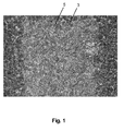
- Fig. 1 shows an illustration of a material according to the invention.
- the material comprises a matrix 3 of silicon carbide and coking as the reinforcing element 5, wherein of the plurality of reinforcing elements recognizable on the picture For the sake of clarity, only one reinforcing element is marked as 5.
- the spherical to ellipsoidal shape of the reinforcing element 5 is in Fig. 1 to recognize. Out Fig. 1 It can be seen that the reinforcing element 5, ie the coke, the matrix 3, ie the silicon carbide passes through. The enforcement is homogeneous.
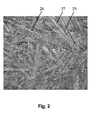
- Fig. 2 shows a further illustration of another material according to the invention.
- the material according to the invention comprises silicon carbide as matrix 23 and coke as reinforcing element 25. Furthermore, the material contains carbon fibers as filler 27.
- the material contains carbon fibers as filler 27.
- only one reinforcing element is identified as 25 and only one filler is identified as 27.
- the mixture is pressed on a hot extrusion press at a pressure of 1.5 MPa and a temperature of 160 ° C for 30 minutes and cured and then demolded.
- the shaped body is heated in a protective gas furnace under a nitrogen atmosphere at a heating rate of 1 K / min to a temperature of 900 ° C. This temperature is maintained for one hour.
- the cooling to room temperature is unregulated.
- This shaped body is infiltrated with silicon in a vacuum oven at temperatures of> 1500 ° C (liquid phase silicization), wherein a portion of the carbon formed in the carbonization reacts with a portion of the introduced silicon to silicon carbide.
- the molding compound 1200 g of ball coke of grain size 0-500 ⁇ m and 300 g of powdered resin (SP 227 from Hexion, Rotterdamm, Netherlands) in an intensive mixer pre-mixed for 2 minutes with 50g-60g - 5% polyvinyl alcohol solution moistened with further mixing and then granulated with the addition of 30-50g ethanol at speeds of 1200-2000U / min for 5 minutes.
- powdered resin SP 227 from Hexion, Rotterdamm, Netherlands
- This granulate is then dried at 40-50 ° C in a drying oven to a residual moisture content of 0.5-1.0% and can then be screened into various fractions ( ⁇ 1.0 mm, ⁇ 2.0 mm).
- This granulate is then filled into a mold.
- the mixture is pressed on a hot extrusion press at a pressure of 1-2 MPa and a temperature of 160 ° C for 10 to 30 minutes and cured and then demolded.
- the shaped body is heated in a protective gas oven under a nitrogen atmosphere at a heating rate of 1 K / min to a temperature of 900 ° C. This temperature is maintained for one hour.
- the cooling to room temperature is unregulated.
- This shaped body is infiltrated with silicon in a vacuum oven at temperatures of> 1500 ° C (liquid phase silicization), wherein a portion of the carbon formed in the carbonization reacts with a portion of the introduced silicon to silicon carbide.
Landscapes
- Chemical & Material Sciences (AREA)
- Engineering & Computer Science (AREA)
- Ceramic Engineering (AREA)
- Materials Engineering (AREA)
- Organic Chemistry (AREA)
- Structural Engineering (AREA)
- Manufacturing & Machinery (AREA)
- Mechanical Engineering (AREA)
- Metallurgy (AREA)
- Dispersion Chemistry (AREA)
- Inorganic Chemistry (AREA)
- Chemical Kinetics & Catalysis (AREA)
- General Chemical & Material Sciences (AREA)
- Geochemistry & Mineralogy (AREA)
- Life Sciences & Earth Sciences (AREA)
- Ceramic Products (AREA)
- Compositions Of Macromolecular Compounds (AREA)
- Glass Compositions (AREA)
Abstract
Description
- Die vorliegende Erfindung betrifft einen Werkstoff, ein Verfahren zur Herstellung eines Werkstoffs sowie seine Verwendung.
- Werkstoffe für Bauteile wie eine Keramik sind bekannt. Keramische Materialien weisen jedoch im Allgemeinen den Nachteil auf, unter mechanisch und thermisch induzierten Belastungen sprödbrüchig zu sein. Dies schränkt ihre Verwendung stark ein.
- Eine Schlagzähigkeitsverbesserung von Siliciumcarbid mit Kohlenstofffasern oder keramischen Fasern wird daher beispielsweise in der Industrie standardmäßig eingesetzt. Die Nachteile dieser Werkstoffe sind hohe Faserkosten und ein komplizierter Herstellungsprozess, der eine breite Anwendung in der Industrie und insbesondere in Fahrzeugen einschränkt.
- Aufgabe der vorliegenden Erfindung ist daher, einen Werkstoff zur Verfügung zu stellen, der nicht sprödbrüchig ist sowie kostengünstig und einfach herstellbar ist.
- Erfindungsgemäß wird die Aufgabe durch einen Werkstoff gemäß Anspruch 1 sowie durch ein Verfahren gemäß Anspruch 12 gelöst.
- Erfindungsgemäß wird ein Werkstoff zur Verfügung gestellt, der eine Matrix und mindestens ein darin eingebrachtes Verstärkungselement umfasst. Die Matrix ist ausgewählt aus der Gruppe, bestehend aus Kunststoff, Kohlenstoff, Keramik, Glas, Ton, Metall und deren Kombinationen. Das Verstärkungselement weist eine kugel- bis ellipsoidförmige Gestalt auf und ist zwiebelschalenartig aufgebaut. Im Sinne der vorliegenden Erfindung wird mit dem Ausdruck "zwiebelschalenartig aufgebaut" ein mehrschichtiger Aufbau bezeichnet, der eine Innenschicht von kugel- bis ellipsoidförmiger Gestalt umfasst, die vollständig oder teilweise von mindestens einer Zwischenschicht und einer Außenschicht bedeckt ist. Der Ausdruck "mehrschichtiger Aufbau" bedeutet, dass das Verstärkungselement mindestens 3 Schichten, d.h. eine Innenschicht, eine Außenschicht und mindestens eine Zwischenschicht aufweist, wobei die Zwischen- und Außenschichten die Innenschicht zumindest teilweise umhüllen. Vorzugsweise ist die Matrix von dem mindestens einen Verstärkungselement homogen durchsetzt.
- Durch die Durchsetzung der Matrix mit mindestens einem zwiebelschalenartig aufgebauten kugel- bis ellipsoidförmigen Verstärkungselement wird ein Werkstoff mit einer verbesserten Bruchzähigkeit erhalten, der zudem eine hohe Festigkeit und hohe Steifheit aufweist. Weiterhin können im Hinblick auf faserverstärkte Werkstoffe Kosten aufgrund geringerer Rohmaterialkosten und des möglichen Einsatzes von Massenformgebungsprozessen wie beispielsweise Spritzgießen, Schlickergießen oder Extrudieren eingespart werden. Diese Formgebungsverfahren bieten sich aufgrund der hervorragenden Fließfähigkeit der Masse an, welche insbesondere in dem Zusatz sphärolithischer Teilchen zu sehen ist.
- Die Auswahl der Materialien der Matrix und des Verstärkungselements ist derart, dass das Verstärkungselement von der Matrix weder während der Verarbeitung noch bei der Verwendung des Werkstoffes vollständig beschädigt oder zerstört wird. Das Material der Matrix und das Material des Verstärkungselements können so ausgewählt sein, dass sie sich inert zueinander verhalten. Alternativ kann das Verstärkungselement auch mit einem Mittel vorbehandelt sein, das als Schutz gegenüber der Matrix wirkt (Beschichtung).
- In einer bevorzugten Ausführungsform stellt die Matrix einen Kunststoff, Kohlenstoff, eine Keramik, ein Glas, ein Ton, ein Metall oder eine Kombination aus Keramik und Metall dar.
- In einer weiteren bevorzugten Ausführungsform stellt die Matrix einen Kunststoff dar. Ein Beispiel für einen Kunststoff stellt Polystyrol dar, der erfindungsgemäße Werkstoff weist dann eine gute Zähigkeit auf. In einer weiteren bevorzugten Ausführungsform stellt die Matrix einen Kunststoff, der carbonisierbar ist, insbesondere einen Binder wie ein kohlenstoffhaltiges Bindemittel aus der Gruppe der Kunstharze dar. Ein bevorzugter Binder aus der Gruppe der Kunstharze stellt ein Phenolharz, insbesondere Novolak, dar. Aber auch andere Harze, die beim Carbonisieren eine gute Koksausbeute erzielen, wie Furanharze, Polyimide oder Polyarylatharze wie z. B. Polyphenylene sind als Matrix geeignet.
- Die Matrix aus einem Kunstharz kann durch Carbonisierung zu einer Kohlenstoffmatrix umgewandelt werden. In einer besonders bevorzugten Ausführungsform stellt die Matrix Kohlenstoff, insbesondere einen nicht graphitischen, d.h. spröden, Kohlenstoff dar. Der Werkstoff kann auch eine Matrix aufweisen, die eine Kombination aus Kohlenstoff und Kunststoff aufweist. Ein Werkstoff mit einer derartigen Matrix ist aus einer nicht vollständigen Carbonisierung des Kunstharzes erhältlich.
- In einer anderen bevorzugten Ausführungsform stellt die Matrix eine Keramik dar. Im Sinne der vorliegenden Erfindung wird unter dem Begriff "Keramik" ein keramischer Werkstoff verstanden, der nichtoxidische Keramiken, oxidische Keramiken, keramische Polymere und Zemente umfasst.
- Bevorzugt stellt die Keramik eine nichtoxidische Keramik wie Siliciumcarbid dar. Ein Kokspartikel-verstärkter Werkstoff mit einer Matrix aus Siliciumcarbid weist eine hohe Härte, Chemikalien-, Oxidations- und Wärmebeständigkeit auf. Erhalten wird solch ein Werkstoff, indem Koks als Verstärkungselement in eine Matrix aus Kunstharz wie beispielsweise Phenolharz eingebracht wird, welches carbonisiert, ggf. bei Graphitierungstemperaturen behandelt und anschließend siliziert wird. Die Matrix kann daher auch eine Kombination aus Kohlenstoff und Siliciumcarbid umfassen.
- Die Matrix stellt in einer weiteren bevorzugten Ausführungsform eine oxidische Keramik dar. Beispiele für geeignete oxidische Keramiken stellen Siliciumoxid, Aluminiumoxid, Zirkonoxid und Mischoxide dar, die neben den vorstehend genannten zusätzlich Magnesiumoxid, Titanoxid oder Boroxid enthalten können.
- In einer weiteren bevorzugten Ausführungsform stellt die Matrix ein keramisches Polymer dar. Geeignete Polymere stellen bevorzugt polymere Verbindungen des Siliciums, Bor und/oder Phosphors wie beispielsweise Polysiloxane, Polysilane, Polysilizane, Polybornitride, Polyphosphate oder Polyphosphazene dar. Die Matrix umfasst in einer weiteren bevorzugten Ausführungsform eine auf Pyrolyse (thermische Zersetzung des Polymers unter Luftausschluß) eines anorganischen Polymers basierende Keramik. Beispielsweise stellt die Matrix SiBCN dar, welche durch Pyrolyse eines borhaltigen Polysilazans unter Stickstoff bei Temperaturen bis 1000°C erhalten wird. Ein Werkstoff mit einer derartigen Matrix ist thermisch stabil, oxidations- und korrosionsbeständig.
- In einer weiteren bevorzugten Ausführungsform stellt die Matrix Zement dar. Im Sinne der vorliegenden Erfindung umfasst der Ausdruck "Zement" auch Beton. Insbesondere Portlandzement ist als Matrix geeignet. Weiterhin sind Hochofenzement, der 15 bis 69 Gewichtsteile Portlandzement und Hüttensand in einem Anteil von 31 bis 85 Gewichtsteile enthält, und Eisenportlandzement geeignet, der mindestens 70 Gewichtsteile Portlandzement und höchstens 30 Gewichtsteile Hüttensand enthält, wobei unter Hüttensand ein durch schnell gekühlter Hochofenschlacke erzeugtes silikatisches Produkt verstanden wird. Auch Tonerdezement ist als Matrix geeignet.
- In einer anderen bevorzugten Ausführungsform stellt die Matrix ein Metall dar. Beispiele für Metalle sind Aluminium oder Magnesium.
- In einer weiteren bevorzugten Ausführungsform umfasst die Matrix eine Kombination aus Keramik und Metall. Das Metall ist bevorzugt ausgewählt aus der Gruppe, bestehend aus Aluminium, Eisen, Chrom, Nickel, Kupfer, Titan, Zirkon, Molybdän, Vanadium, Wolfram, Tantal, Niob und den Legierungen Bronze und Messing. Die Keramik stellt bevorzugt eine oxidische Keramik wie Aluminiumoxid, Zirkonoxid, Mischoxid aus zwei oder mehreren aus der Gruppe aus Aluminiumoxid, Zirkonoxid, Siliciumdioxid, Titanoxid, Magnesiumoxid, Boroxid dar. Alternativ stellt die Keramik eine nichtoxidische Keramik wie Siliciumcarbid dar. Der Massenanteil des Metalls in der Keramik liegt in dem Bereich von 2 bis 20 %, bevorzugt 5 bis 10 %.
- In einer weiteren bevorzugten Ausführungsform stellt die Matrix ein Glas dar. Im Sinne der vorliegenden Erfindung wird unter einem Glas ein Silikat verstanden, das eine amorphe, d.h. ohne Kristallisation erstarrte, d. h. metastabile, beim Erwärmen nur allmählich erweichende unterkühlte Schmelze darstellt. Als Matrix geeignet ist Silicatglas, Borosilicatglas, Alumosilicatglas oder Phosphosilicatglas. Als Matrix besonders geeignet ist Quarzglas.
- In einer weiteren bevorzugten Ausführungsform stellt die Matrix einen Ton dar. Beispiele für einen Ton stellen Lehm oder ein Ziegelerzeugnis dar. Gegenüber einem reinen Ton weist der erfindungsgemäße Werkstoff eine höhere Festigkeit auf und ist beständiger gegenüber dem Auftreten von Rissen.
- Das Verstärkungselement ist bevorzugt ausgewählt aus der Gruppe, bestehend aus Kohlenstoff, Keramik, deren Kombination und in Kombination mit Metall. Bevorzugt besteht das Verstärkungselement aus Kohlenstoff.
- Das Verstärkungselement ist zwiebelschalenartig aufgebaut und weist mindestens 3 Schichten auf. Zumindest die Zwischen- und Außenschichten des Verstärkungselements sind bevorzugt derart gewählt, dass sie sich inert gegenüber der Matrix verhalten und das Kernmaterial in Form der Innenschicht vollständig umhüllen, wenn das Kernmaterial sich reaktiv zu der Matrix verhält. Die Zwischen- und Außenschichten dienen dann als Hülle für das Kernmaterial des Verstärkungselements und sind insbesondere ein Schutz, wenn eine mögliche Reaktion zwischen Kernmaterial und Matrix unterbunden werden soll. Die Innen-, mindestens eine Zwischen- und Außenschichten können unterschiedliche Materialien umfassen. Alternativ sind die Innen-, mindestens eine Zwischen- und Außenschichten aus einem Material wie beispielsweise Kohlenstoff aufgebaut. In einer bevorzugten Ausführungsform stellt das Verstärkungselement Koks dar, der sphärolitisch mit einer Zwiebelschalenstruktur vorliegt.
- Das schalen- bzw. schichtenförmige Verstärkungselement kann Kohlenstoffschichten aufweisen. Besonders bevorzugt stellt das Verstärkungselement Koks dar, der schwer bis nicht graphitierbar, hochisotrop, hart und wenig porös ist und eine niedrige spezifische Oberfläche aufweist. Der durch Röntgenbeugung ermittelbare mittlere Schichtabstand d002 des Kokses beträgt bevorzugt mindestens 0,35 nm, und die scheinbare Stapelhöhe Lc liegt bevorzugt unterhalb von 5,0 nm. Ein derartiger Koks ist aus Rohölfraktionen oder Steamcrackerrückständen erhältlich, welche beim Quenchen von Reaktionsgas in der Synthese von ungesättigten Kohlenwasserstoffen (Acetylen) verwendet wird, wobei das Quenchöl/Russgemisch zu einem Koker abgeführt wird, der auf etwa 500°C erhitzt wird. Flüchtige Bestandteile des Quenchöls verdampfen in dem Koker, von dessen Boden der Koks entnommen werden kann. Auf diese Weise wird ein feinkörniger zwiebelschalenartiger Koks gewonnen, der neben den vorstehend beschriebenen Eigenschaften hochrein ist und wenig bis keine Asche- und Mineralstoffgehalte aufweist. Der Koks kann aber auch hohe Asche- und Mineralstoffgehalte aufweisen und weniger rein sein. Die Reinheit des Kokses ist von der Reinheit des verwendeten Quenchöls abhängig. Üblicherweise ist Koks ein Feststoff mit hohem Kohlenstoffgehalt und im nicht graphitischen Zustand und wird durch Pyrolyse von organischem Material hergestellt, welches zumindest teilweise während des Carbonisierprozesses einen flüssigen oder flüssigkristallinen Zustand durchlaufen hat. Vermutlich behindern die Russpartikel die Ausbildung einer ungestörten Flüssigphase (Mesophase) und liefern einen Koks hoher Härte und schlechter Graphitierbarkeit. Der aus dem Gasquenchverfahren erhaltene Koks ist daher durch Wärmebehandlung bei Temperaturen oberhalb von 2200°C nur wenig graphitierbar. Nach einer Wärmebehandlung bei 2800°C beträgt beispielsweise der aus dem Röntgenbeugungspeak d002 ermittelte mittlere Schichtabstand c/2 0,34 nm oder mehr und die Kristallatgröße in die c-Richtung Lc weniger als 20 nm und die Kristallatgröße La110 weniger als 50 nm, bevorzugt weniger als 40 nm. Besonders bevorzugt ist der Koks von hoher Härte, schlecht graphitierbar und der mittlere Schichtabstand c/2 nach 2800°C Temperaturbehandlung größer oder gleich 0,34 nm, welches einem maximalen Graphitierungsgrad nach Maire und Mehring von maximal 46,5 % entspricht.
- Alternativ weist das Verstärkungselement mindestens drei Keramikschichten auf. Beispielsweise umfasst das Verstärkungselement Aluminiumoxid. Zwiebelschalenartiges Aluminiumoxid mit kugel- bis ellipsoidförmiger Gestalt ist durch eine zumindest teilweise Umhüllung eines Aluminiumoxid-Korns mit weiteren Aluminiumoxidschichten erhältlich.
- Weiterhin alternativ kann das Verstärkungselement eine Kombination aus Kohlenstoff und Keramik aufweisen. Beispielsweise kann die Innenschicht des Verstärkungselements Kohlenstoff darstellen, und die mindestens eine Zwischen- und Außenschichten können Kohlenstoff und Siliciumcarbid umfassen. Alternativ kann das Verstärkungselement eine Kombination aus Kohlenstoff und Siliciumdioxid umfassen.
- Weiterhin alternativ kann das Verstärkungselement zusätzlich zu Kohlenstoff und/oder Keramik ein Metall umfassen. Beispiele für ein Metall umfassen Aluminium, Eisen, Chrom oder Nickel.
- Das schalenförmig aufgebaute Verstärkungselement kann weiterhin mindestens eine Verstärkungskomponente in seiner Struktur aufweisen. Ein Beispiel hierfür ist der Einbau von Russpartikeln, wie sie bei der Acetylensynthese zwangsläufig entstehen. Eine Alternative zu einem Koks aus der Acetylensynthese sind sphäroidale Kokspartikel aus dem Fluid / Flexicoking Verfahren. Auch hier handelt es sich um schlecht graphitierbare, harte Kokse, für die die oben gemachten röntgenstrukturellen Angaben ebenfalls zutreffend sind.
- In einer bevorzugten Ausführungsform des erfindungsgemäßen Werkstoffs stellt das Verstärkungselement Koks dar und die Matrix umfasst Siliciumcarbid. Noch bevorzugter besteht die Matrix aus Siliciumcarbid und das mindestens eine darin eingebrachte Verstärkungselement stellt sphärolitischen Koks dar.
- In einer bevorzugten Ausführungsform weist das Verstärkungselement ein Länge-/Durchmesser-Verhältnis von 1 bis 10, bevorzugter von 1 bis 5, bevorzugter von 1 bis 3, auf. Je mehr sich die Gestalt des Verstärkungselements an eine kugelförmige Struktur annähert, desto besser sind die Fließfähigkeit der Masse und die mechanischen Eigenschaften des Werkstoffes.
- Das Verstärkungselement kann alternativ thermisch vorbehandelt sein. Insbesondere wenn das Verstärkungselement Kohlenstoff (Koks) umfasst, ist eine thermische Vorbehandlung vorteilhaft. Die thermische Vorbehandlung umfasst eine Calcinierung, d.h. eine Wärmebehandlung des Verstärkungselements bei einer Temperatur in dem Bereich zwischen 700 bis 1600°C, bevorzugt 1000 bis 1500°C, bevorzugter 1100 bis 1300°C, ggf. unter einer reduzierenden Atmosphäre. Eine derartige Behandlung führt insbesondere zum Verdampfen von Wasser, flüchtigen brennbaren Stoffen wie beispielsweise Kohlenwasserstoffen wie Methan, Kohlenmonoxid bzw. Wasserstoff.
- Weiterhin alternativ kann das Verstärkungselement mit einem Oxidationsschutz vorbehandelt sein. Der Oxidationsschutz ist insbesondere dann von Interesse, wenn das Verstärkungselement ein oxidationsempfindliches Material darstellt. Als Oxidationsschutz kommen Verbindungen in Frage, die leichter oxidierbar sind als das Verstärkungselement. Beispielsweise kommen in dem Fall von Kohlenstoff (Koks) als Verstärkungselement folgende Oxidationsschutzmittel in Betracht. Borsalze können in den Koks eingebracht sein und weiterhin alternativ oder zusätzlich kann der Koks mit Siliciumverbindungen vorbehandelt sein, die Siliciumdioxid-Häute bilden.
- Weiterhin alternativ kann das Verstärkungselement durch Imprägnierung vorbehandelt sein. Die Imprägnierung umhüllt das Verstärkungselement und wirkt als Schutzmittel gegen mögliche Reaktionen des Verstärkungselements mit Komponenten der Matrix. Weiterhin kann das Verstärkungselement alternativ anoxidiert sein.
- In einer bevorzugten Ausführungsform der vorliegenden Erfindung enthält die Matrix weiterhin mindestens einen Füllstoff. D.h. neben dem Verstärkungselement von kugel- bis ellipsoidförmiger Gestalt und mit einem zwiebelschalenartigen Aufbau ist die Matrix von mindestens einem Füllstoff durchsetzt. Der Füllstoff kann eine Faser darstellen. Die Faser kann als Langfaser in Form von einem Gelege, Band, Gewebe, Gewirke, Gestrick oder Flies oder als Kurzfaser vorliegen. Der Füllstoff umfasst bevorzugt eine Kohlenstofffaser. Alternativ oder zusätzlich kann der Füllstoff ein kugel- bis ellipsoidförmiges Partikel darstellen. Beispielsweise ist der Füllstoff ausgewählt aus der Gruppe, bestehend aus Russ, Zirkondioxid, Siliciumdioxid, Aluminiumnitrid, Aluminiumoxid, Titandioxid, Titancarbid, Wolframcarbid und deren Mischungen.
- Beispielsweise weist der erfindungsgemäße Werkstoff vorteilhaft als Füllstoff eine Kohlenstofffaser, als Verstärkungselement sphärolithischen Koks und als Matrix ein carbonisiertes Phenolharz wie Novolak, d.h. eine Kohlenstoffmatrix, auf. Er ist in der gewünschten Geometrie und Abmessung insbesondere als Bremsscheibe geeignet.
- Die Korngröße des Verstärkungselements beeinflusst die Dichte, Festigkeit, Aufnahmekapazität der Matrix und die Bruchenergie des Werkstoffs. In einer bevorzugten Ausführungsform beträgt die Korngröße des Verstärkungselements mindestens 1 µm. Bevorzugt liegt die Korngröße in dem Bereich von 5 µm bis 500 µm. Bevorzugter liegt die Korngröße des Verstärkungselements in dem Bereich von 10 bis 125 µm. Besonders bevorzugt liegt die Korngröße des Verstärkungselements in dem Bereich von 10 bis 60 µm. Je feinkörniger das Verstärkungselement ist, desto höher sind die Festigkeit und Dichte des Werkstoffs. Die gewünschte Korngröße des Verstärkungselements ist beispielsweise durch Sieben des Verstärkungselements erhältlich.
- Der Werkstoff weist bevorzugt 30 bis 95 Gew.-%, bevorzugt 50 bis 90 Gew.-%, bevorzugter 75 bis 60 Gew.-%, Verstärkungselement und 5 bis 70 Gew.-%, bevorzugt 10 bis 50 Gew.-%, bevorzugter 25 bis 40 Gew.-%, Matrix auf, bezogen auf das Gesamtgewicht des Werkstoffs. Weiterhin weist der Werkstoff optional bis zu 40 Gew.-% Füllstoff auf, bezogen auf das Gesamtgewicht des Werkstoffs.
- Ein Verfahren zur Herstellung des erfindungsgemäßen Werkstoffes umfasst die folgenden Schritte:
- a) Bereitstellen von mindestens einem Verstärkungselement von kugel- bis ellipsoidförmiger Gestalt, das zwiebelschalenartig aufgebaut ist, und
- b) Einbringen des Verstärkungselements in eine Matrix, wobei die Matrix ausgewählt ist aus der Gruppe, bestehend aus Kunststoff, Kohlenstoff, Keramik, Glas, Ton, Metall und deren Kombinationen.
- Durch das Einbringen von mindestens einem Verstärkungselement von kugel- bis ellipsoidförmiger Gestalt, das zwiebelschalenartig aufgebaut ist, in eine Matrix wird ein Werkstoff erhalten, der hochfest ist und eine hohe Bruchzähigkeit aufweist. Zudem ist die Ausgangsmasse gut formbar. Die Art des Einbringens des Verstärkungselements in die Matrix hängt von der Natur und Art der Matrix und des Verstärkungselements ab. Das Einbringen kann durch Infiltration, Druckguss, Imprägnieren des Verstärkungselements oder Mischen von ihm mit der Matrix durchgeführt werden.
- Das Mischen des Verstärkungselements mit der Matrix ist insbesondere von Vorteil, wenn das Material des Verstärkungselements und das Material der Matrix eine gute Haftfähigkeit aufweisen. Eine Infiltration ist von besonderem Vorteil, wenn die Matrix ein Metall darstellt oder wenn die Matrix ein anorganisches Harz wie ein Polymer darstellt, das pyrolisiert werden kann. Unter Druckguss wird im Sinne der vorliegenden Erfindung eine Infiltration unter Druck verstanden. Eine Imprägnierung des Verstärkungselements ist insbesondere bei einem Polymer oder Kunststoff oder Harz als Matrix vorteilhaft.
- Ein Wärmefließpressen ist insbesondere von Vorteil, wenn das Verstärkungselement Koks darstellt, wobei der Koks mit einem Kunstharz wie Novolak gemischt wird und einem Wärmefließpressen oder Spritzgussverfahren unterzogen wird. Anschließend kann das Kunstharz zu einer Kohlenstoffmatrix carbonisiert werden. Anschließend kann der Werkstoff, der die Kohlenstoffmatrix und das Koks-Verstärkungselement umfasst, einer Silizierung zur Bildung einer Siliciumcarbid-Matrix unterzogen werden. Das Einbringen des Verstärkungselements in die Matrix kann bei Raumtemperatur oder bei erhöhter Temperatur, drucklos oder unter Druck realisiert werden.
- Bevorzugt wird während des Schritts b) des erfindungsgemäßen Verfahrens die Matrix, in die das Verstärkungselement eingebracht wird, geformt. Beispielsweise kann eine Masse aus Matrix und Verstärkungselement in einer Wärmefließpresse zu einer gewünschten Form geformt werden. Durch die kugel- bis ellipsenförmige Gestalt des Verstärkungselements wird zusammen mit der Matrix eine Pressmasse erhalten, die sich sehr gut formen lässt. Es reichen niedrige Drücke unter Temperatur, um die Masse zum Fließen zu bringen.
- In einer bevorzugten Ausführungsform umfasst Schritt b) des erfindungsgemäßen Verfahrens den Schritt Einbringen von mindestens einem Verstärkungselement und mindestens einem Füllstoff in die Matrix. Als Füllstoff kann eine Faser wie eine Kohlenstofffaser oder ein kugel- bis ellipsoidförmiges Partikel wie Russ, Zirkondioxid, Siliciumdioxid, Aluminiumnitrid, Aluminiumoxid, Titandioxid, Titancarbid, Wolframcarbid oder deren Mischungen eingesetzt werden. In dieser Ausführungsform wird das mindestens eine Verstärkungselement zusammen mit dem mindestens einen Füllstoff in die Matrix eingebracht. Vorzugsweise werden alle Ausgangsstoffe des erfindungsgemäßen Werkstoffs gemischt. In einer besonders bevorzugten Ausführungsform werden sphärolithischer Koks als Verstärkungselement und Kohlenstofffasern als Füllstoff mit einem Phenolharz wie Novolak gemischt.
- In einer bevorzugten Ausführungsform umfasst das erfindungsgemäße Verfahren den folgenden Schritt c) Erzeugen einer Porosität zumindest an der Oberfläche des Werkstoffs im Anschluss an Schritt b). Durch diesen Schritt wird dem erfindungsgemäßen Werkstoff eine definierte Porosität verliehen. Somit wird anhand des erfindungsgemäßen Verfahrens nicht nur ein unporöser Werkstoff, sondern ebenfalls ein poröser Werkstoff erhalten, welcher als Bauteil Verwendung findet, das eine Trägerstruktur erfordert. Zum Beispiel ist eine definierte Porosität des erfindungsgemäßen Werkstoffs an seiner Oberfläche von Vorteil, wenn er als Katalysatorträger wie beispielsweise ein Russpartikelfilter Anwendung findet. Besondere Vorteile bietet die Durchführung dieser Verfahrensvariante auch bei der Verwendung des erfindungsgemäßen Werkstoffs als Knochenersatzmaterial, weil in seine Poren Knochenzellen eingelagert werden können, welche in der Lage sind, in einer durch den erfindungsgemäßen Werkstoff vorgegebenen gewünschten dreidimensionalen Struktur zu wachsen, wenn sie zusammen mit dem Werkstoff in den Körper eines Patienten implantiert sind. Hier kann die Porosität nicht nur an der Oberfläche des Werkstoffs erzeugt werden, sondern der ganze Werkstoff von Poren durchzogen werden. Auf diese Weise wird ein Werkstoff als dreidimensionales Trägergerüst ausgebildet, das, wenn es im Körper eines Patienten implantiert ist, von Zellen und Gefäßen durchwachsen werden kann.
- Beispielsweise kann eine definierte Porosität bei dem erfindungsgemäßen Werkstoff, der Siliciumcarbid als Matrix und Koks als Verstärkungselement umfasst, durch Oxidation von Kokskörnern an der Oberfläche des Werkstoffs mittels Luft erzeugt werden. Die Oxidation des Werkstoffs läuft unter sehr kontrollierbaren und definierten Fortschrittsraten ab. Die Porengrößen und -verteilung hängen dabei von den eingesetzten Koks-Korngrößen und -mengen ab.
- In einer bevorzugten Ausführungsform weist das bei dem erfindungsgemäßen Verfahren eingesetzte Verstärkungselement die folgenden Eigenschaften auf: Sein Länge-/Durchmesser-Verhältnis beträgt 1 bis 10, seine Korngröße ist größer als 1 µm und sein Material stellt Kohlenstoff, Keramik, deren Kombination und in Kombination mit Metall dar. Besonders bevorzugt wird bei dem erfindungsgemäßen Verfahren sphärolithischer Koks als Verstärkungselement verwendet.
- In einer bevorzugten Ausführungsform umfasst Schritt b) des erfindungsgemäßen Verfahrens die folgenden Schritte Mischen des Verstärkungselements mit einem Binder, Carbonisieren des Binders und optional Silizieren und Umsetzen der durch die Carbonisierung des Harzes entstandenen Kohlenstoffmatrix zu Siliciumcarbid. In dieser Ausführungsform stellt das mindestens eine Verstärkungselement bevorzugt sphärolithischer Koks dar.
- Als Binder können kohlenstoffhaltige Bindemittel aus der Gruppe der Kunstharze verwendet werden. Ein bevorzugter Binder aus der Gruppe der Kunstharze stellt Phenolharz dar. Ein bevorzugtes Phenolharz stellt Novolak dar. Aber auch andere Harze, die beim Carbonisieren eine gute Koksausbeute erzielen, wie Furanharze, Polyimide oder Polyarylatharze wie z. B. Polyphenylene, können eingesetzt werden.
- Zur Herstellung einer formbaren Masse aus dem Verstärkungselement und dem Binder werden 30 bis 95 Gew.-%, bevorzugt 50 bis 90 Gew.-%, bevorzugter 75 bis 60 Gew.-% Verstärkungselement mit 5 bis 70 Gew.-%, bevorzugt 10 bis 50 Gew.%, bevorzugter 25 bis 40 Gew.-% Binder vorzugsweise bei Raumtemperatur gemischt. Nach der Beendigung des Mischvorgangs, der bis zu 30 Minuten beanspruchen kann, wird die Mischung in die Form einer Gesenk- oder in den Pressbehälter einer isostatischen Presse gefüllt, verdichtet und ggf. gehärtet. Der auf die Masse einwirkende Pressdruck beträgt vorzugsweise 0,1 bis 5,0 MPa, bevorzugter 0,5 bis 4,0 MPa. Die für die Härtung aufzuwendende Zeit, während der auch der Pressdruck aufrechterhalten wird, hängt von der Größe des herzustellenden Formkörpers und von dem verwendeten Kunstharz ab. Bei Binderharzen dauert der Härtungsvorgang im Allgemeinen 30 Minuten bis 5 Stunden. Nach dem Aushärten wird der Formkörper der Pressform entnommen und carbonisiert. Die bevorzugt angewandte Endtemperatur liegt im Bereich von 850 bis 950°C. Wie bei allen Carbonisierungs- oder Brennschritten dieses Herstellungsverfahrens sollte so gearbeitet werden, dass der Zutritt von oxidierend wirkenden Substanzen zu dem Werkstoff, der gebrannt wird, ausgeschlossen ist. Der Brennprozess wird in diesem Falle so ausgeführt, dass eine hohe Carbonisierungsrate aus dem Binder oder dem Bindersystem resultiert. Dies gelingt durch Anwendung eines Druckverkokungsverfahrens oder dadurch, dass der Temperaturgradient in der Aufheizphase im Bereich von 300 bis 600°C niedrig, bevorzugt unter 4°C pro Stunde, gehalten wird. Für die Optimierung der Bruchdehnung des Endprodukts dieses Herstellungsverfahrens kann es vorteilhaft sein, diesem Carbonisierungsprozess noch einen Graphitierungsschritt nachzuschalten. Die Durchführung einer solchen Maßnahme ist jedoch nicht zwingend und kann aus wirtschaftlichen Gründen auch unterbleiben. Verfahren zum Graphitieren sind bekannt. Vorzugsweise wird bei Temperaturen von 1800 bis 2200°C gearbeitet.
- In einer bevorzugten Ausführungsform wird der Werkstoff anschließend einem Silizieren und Umsetzen der durch das Carbonisieren des Harzes entstandenen Kohlenstoffmatrix zu Siliciumcarbid unterzogen. Hierdurch wird hochfestes Siliciumcarbid-Bauteil mit hervorragender Bruchzähigkeit erhalten. Hierzu kann das im Stand der Technik bekannte Silizieren mit Flüssigsilicium angewandt werden. Bei diesem Verfahren befindet sich der zu silicierende Körper in einem Behälter, auf dessen Boden sich geschmolzenes Silicium befindet. Das Silicium infiltriert infolge seiner ausgezeichneten Benetzbarkeit gegenüber Kohlenstoff durch Kapillarkräfte die Matrix des Werkstoffs und reagiert mit dem Kohlenstoff zu Siliciumcarbid. Bei genügend hohen Temperaturen, die im Bereich von ca. 2200°C liegen und ausreichend langen Einwirkungszeiten können die Kohlenstoffkörper bei Vorhandensein genügender Mengen Siliciums vollständig in SiC umgewandelt werden. Es sollte auch beachtet werden, dass graphitische, sehr gut geordnete Kohlenstoffformen langsamer zu SiC umgesetzt werden als solche, die kristallographisch gesehen weniger gut geordnet sind wie beispielsweise nur gebrannter, nicht graphitierter Kohlenstoff. Wenn das Verstärkungselement des Werkstoffs Koks darstellt, müssen bei der Durchführung dieses Verfahrensschrittes deshalb die Verfahrensbedingungen so gewählt werden, dass im Wesentlichen nur die Matrix in Siliciumcarbid umgewandelt und das Verstärkungselement im Wesentlichen nicht umgesetzt wird. Das Silicieren kann im Temperaturbereich von 1450 bis 2200°C durchgeführt werden. Bevorzugt wird jedoch im Temperaturbereich von 1500 bis 1750°C unter Vakuum gearbeitet, wobei vorzugsweise das zum Silizieren verwendete Gefäß, bzw. der zum Silizieren verwendete Ofen vor Beginn des Prozesses mit einem Inertgas, beispielsweise mit Argon gespült wird, um Reste reaktiver Gase zu entfernen. Das Aufheizen des Reaktors auf Reaktionstemperatur kann den technischen Gegebenheiten der Silizierungsanlage gemäß schnell geschehen. Nach Erreichen der Silizierungstemperatur beträgt die Zeit, die für das Infiltrieren und Reagieren zu SiC benötigt wird, 10 Minuten bis 1 Stunde. Bevorzugt wird mit einer Imprägnier- und Reaktionszeit von 0,5 Stunden gearbeitet. Die angegebenen Imprägnier- und Reaktionszeiten erlauben eine wirtschaftliche Verfahrensweise. Wo dies die Umstände erfordern, kann auch mit längeren Zeiten gearbeitet werden. Es ist auch ein Silizieren ohne Anwendung von Vakuum möglich. In diesem Falle sollte bei Temperaturen von 2100 bis 2200°C, aber ebenfalls unter Schutzgas siliziert werden. Die Summe von Infiltrier- und Reaktionszeit liegt auch hier zwischen 10 Minuten und einer Stunde, bevorzugt bei 0,25 Stunden. Bei der Silizierung bedient man sich vorteilhafterweise der so genannten Dochttechnik. Hierbei liegen die Körper, die siliziert werden sollen, auf porösen, bezogen auf das Silicium sehr saugfähigen Kohlenstoffkörpern, deren unterer Teil im flüssigen Silicium steht. Das Silicium steigt dann durch diese Dochtkörper in die zu silizierenden Körper, ohne dass letztere direkte Verbindung mit dem Siliciumbad haben. Diese Verfahrensweise erspart aufwendige Putzarbeiten nach dem Silizieren.
- Durch das vorstehende Verfahren kann ein besonders bevorzugter Werkstoff hergestellt werden, wobei optional der Schritt des Erzeugens einer definierten Porosität nachgeschaltet werden kann. Der besonders bevorzugte erfindungsgemäße Werkstoff weist 10 bis 50 Gew.-% Siliciumcarbid als Matrix und 50 bis 90 Gew.-% Koks als Verstärkungselement auf, bezogen auf das Gesamtgewicht des Werkstoffs.
- Der erfindungsgemäße Werkstoff ist kostengünstig. Das erfindungsgemäße Verfahren ermöglicht die Herstellung des Werkstoffes als ein Massenprodukt. Weiterhin kann der erfindungsgemäße Werkstoff in den verschiedensten komplexen Geometrien und mit beliebiger Wandstärke hergestellt werden. Der erfindungsgemäße Werkstoff ist daher universell einsetzbar.
- Der erfindungsgemäße Werkstoff findet insbesondere Verwendung als Friktionsanwendung, Abrasionsschutz, Feuerfestanwendungen, Trägerplatte, Spritzgussteil, Katalysatorträger oder Knochenersatzmaterial.
- Die Verwendung des erfindungsgemäßen Werkstoffs als Friktionsanwendung bietet Vorteile. In der Friktionsanwendung findet der erfindungsgemäße Werkstoff insbesondere Verwendung als ein Bremsbelag. Alternativ kann der erfindungsgemäße Werkstoff auch als eine Bremsscheibe Verwendung finden. Ein Bremsbelag oder eine Bremsscheibe kann mittels des erfindungsgemäßen Werkstoffs kostengünstig als ein Massenprodukt zur Verwendung in Maschinen oder Fahrzeugen wie PKWs hergestellt werden. Ein Bremsbelag oder eine Bremsscheibe, die aus dem erfindungsgemäßen Werkstoff gebildet ist, kann auch beispielsweise in ein Aufzugnotsystem integriert werden.
- Ebenfalls besonders geeignet ist der erfindungsgemäße Werkstoff zur Verwendung als ein Abrasionsschutz, da er verschleißbeständig ist. Der Abrasionsschutz stellt insbesondere eine Auskleidung für ein Rohr, einen Zyklon oder einen Auspuff dar. Hier ist die Möglichkeit, den Werkstoff in Form eines sehr dünnen Bauteils herzustellen, von besonderem Vorteil. Da der erfindungsgemäße Werkstoff als ein Bauteil mit beliebiger Wandstärke herstellbar und hochfest ist, eignet er sich ebenfalls zur Verwendung als Ablageplatte oder Schutzplatte. Wegen der hohen Wärmebeständigkeit des erfindungsgemäßen Werkstoffs eignet er sich zur Verwendung als komplex geformte Platte als Hochtemperatur-Bauteil. Auch eignet sich der erfindungsgemäße Werkstoff zur Verwendung als Abrasionsschutz in Form einer Düse wie beispielsweise eine Sandstrahldüse oder eine Raketendüse. Auch als Trägerplatte lässt sich der erfindungsgemäße Werkstoff verwenden. Der erfindungsgemäße Werkstoff lässt sich als Bauteil mit beliebiger Wandstärke herstellen, ist hochfest und wärmebeständig. Er eignet sich daher insbesondere zur Verwendung als eine Trägerplatte bei Ofenprozessen.
- Der erfindungsgemäße Werkstoff bietet ebenfalls Vorteile bei der Verwendung als ein Spritzgussteil. Hierbei kommen Bauteile mit beliebiger Geometrie und Wandstärke in Betracht. Aufgrund seiner hohen Verschleiß- und Wärmebeständigkeit sind insbesondere die folgenden Verwendungen von besonderem Interesse. Von Vorteil ist Verwendung des erfindungsgemäßen Werkstoffs als Motorteil wie beispielsweise als Dichtring, Gleitring oder Laufring. Aufgrund der guten Formbarkeit des erfindungsgemäßen Werkstoffs und der daraus folgenden Möglichkeit zu komplexen Geometrien geformt zu werden, findet er auch als Motorblock Verwendung. Auch seine Verwendung als Zylinderlaufbuchse oder als Kolben ist vorteilhaft. Hierzu kann der erfindungsgemäße Werkstoff weiterhin in ein Metall wie beispielsweise Aluminium oder Magnesium eingegossen bzw. von ihm infiltriert werden. Ebenfalls vorteilhaft ist seine Verwendung als Pumpengehäuse, denn er ist sehr verschleißbeständig. Auch die Verwendung des Werkstoffs als eine Feder ist aufgrund seiner Eigenschaften von Vorteil. Ebenfalls vorteilhaft ist die Verwendung des erfindungsgemäßen Werkstoffs als Turbinenschaufel beispielsweise in einem Lüftungssystem für den Brandfall oder einem Turbolader. Aufgrund seiner hohen Festigkeit, Wärme- und Chemikalienbeständigkeit findet der erfindungsgemäße Werkstoff ebenfalls eine vorteilhafte Verwendung als Rohr, Destillationskolonne, Auspuff, Krümmer oder Ventil. Wenn der erfindungsgemäße Werkstoff leitfähige Bestandteile enthält, ist er zur Verwendung als Elektrodenmaterial oder andere Komponente einer Brennstoffzelle geeignet.
- Eine weitere vorteilhafte Verwendung des erfindungsgemäßen Werkstoffs stellt die Verwendung als Katalysatorträger dar. Hierzu wird an der Oberfläche des erfindungsgemäßen Werkstoffs in seiner Bauteilform an der Oberfläche eine definierte Porosität derart erzeugt, dass ein stabiler Kern bestehen bleibt. Beispielsweise wird, wenn der Werkstoff als Matrix Siliciumcarbid und als Verstärkungselement Koks umfasst, die Oberfläche des Werkstoffs unter Einwirkung von Luft oxidiert, sodass eine definierte Porosität entsteht. Der Werkstoff findet dann insbesondere als ein Filter wie ein Russpartikelfilter Verwendung.
- Eine weitere vorteilhafte Verwendung des erfindungsgemäßen Werkstoffs sieht vor, den Werkstoff als ein Knochenersatzmaterial einzusetzen. Der Werkstoff lässt sich in komplexen Geometrien leicht herstellen und ist somit zur Formung von komplexen Knochenteilstrukturen geeignet. Weiterhin ist der Werkstoff hochfest und gegenüber Körperflüssigkeiten beständig. Daher ist es möglich, den Werkstoff direkt in den Körper eines Patienten als Knochenersatzmaterial in beliebiger Größe und Gestalt zu implantieren. Beispielsweise ist es möglich, anhand von Aufnahmen, die mittels eines Computertumografen erstellt werden können, den Werkstoff als passgenaues Ersatzstück für das fehlende Knochenteil herzustellen. Weiterhin bietet der Werkstoff, insbesondere wenn er als Matrix Siliciumcarbid und als Verstärkungselement Koks aufweist, die Möglichkeit derart definiert oxidiert zu werden, dass eine gewünschte Porosität erzeugt wird. Der Werkstoff eignet sich daher auch als maßgeschneidertes Trägergerüst für die Züchtung von körpereigenen Knochenzellen, das in den Körper eines Patienten mit Knochenverlust implantiert wird, damit Trägergerüst und Knochen mittels der gezüchteten Knochenzellen zusammenwachsen können.
- Weitere Merkmale und Vorteile der Erfindung werden nun unter Bezugnahme auf die nachfolgenden Figuren erläutert, ohne diese auf sie einzuschränken.
- Es zeigen:
- Fig. 1
- eine Abbildung eines erfindungsgemäßen Werkstoffs, und
- Fig. 2
- eine weitere Abbildung eines weiteren erfindungsgemäßen Werkstoffs.
-
Fig. 1 zeigt eine Abbildung eines erfindungsgemäßen Werkstoffs. Der Werkstoff umfasst eine Matrix 3 aus Siliciumcarbid und als Verstärkungselement 5 Koks, wobei von der Vielzahl der auf der Abbildung erkennbaren Verstärkungselemente der Anschaulichkeit halber nur ein Verstärkungselement als 5 gekennzeichnet ist. - Die kugel- bis ellipsoidförmige Gestalt des Verstärkungselements 5 ist in
Fig. 1 zu erkennen. AusFig. 1 ist ersichtlich, dass das Verstärkungselement 5, d.h. der Koks, die Matrix 3, d.h. das Siliciumcarbid, durchsetzt. Die Durchsetzung ist homogen. -
Fig. 2 zeigt eine weitere Abbildung eines weiteren erfindungsgemäßen Werkstoffs. Der erfindungsgemäße Werkstoff umfasst als Matrix 23 Siliciumcarbid und als Verstärkungselement 25 Koks. Weiterhin enthält der Werkstoff Kohlenstofffasern als Füllstoff 27. Der Anschaulichkeit halber ist von der Vielzahl der auf der Abbildung erkennbaren Verstärkungselemente und Füllstoffe nur ein Verstärkungselement als 25 gekennzeichnet und nur ein Füllstoff als 27 gekennzeichnet. Wie inFig. 2 ersichtlich ist, durchsetzen Kokskugeln als Verstärkungselement 25 und die Kohlenstofffasern als Füllstoff 27 die Siliciumcarbid-Matrix 23. Auch hier ist die kugel- bis ellipsoidförmige Gestalt des Verstärkungselements 25 gut zu erkennen. - Weitere Merkmale und Vorteile der Erfindung werden nun unter Bezugnahme auf Beispiele erläutert, ohne diese auf sie einzuschränken.
- Für die Herstellung von Formkörpern mit kugelförmigen Koks für verbesserte Bruchzähigkeit werden
1275 g Kugelkoks der Körnung 0-125 µm und
225 g Pulverharz (SP 227 der Fa. Hexion, Rotterdamm, Niederlande)
in einem Intensivmischer 2 Minuten gemischt und anschließend in eine Pressform eingefüllt. - Die Mischung wird auf einer Warmfließpresse bei einem Druck von 1,5 MPa und einer Temperatur von 160 °C 30 Minuten verpresst und ausgehärtet und anschließend entformt.
- Der Formkörper wird in einem Schutzgasofen unter Stickstoffatmosphäre mit einer Aufheizrate von 1 K/min auf eine Temperatur von 900°C erhitzt. Diese Temperatur wird eine Stunde gehalten. Die Abkühlung auf Raumtemperatur erfolgt ungeregelt.
- Dieser Formkörper wird mit Silizium in einem Vakuumofen bei Temperaturen von >1500°C infiltriert (Flüssigphasensilizierung), wobei ein Teil des bei der Carbonisierung gebildeten Kohlenstoffs mit einem Teil des eingebrachten Siliziums zu Siliziumcarbid reagiert.
- Dabei entsteht ein hochfestes CSiC- Bauteil mit verbesserter Bruchzähigkeit, das jedoch keine Fasern enthält. Seine Eigenschaften sind in der nachstehenden Tabelle zusammengefasst.
Tabelle Biegefestigkeit E-Modul Dehnung W-Bruch Dichte CTE 20/200 Wärmeleitfähigkeit [MPa] [GPa] [%] [Nmm] [g/cm3] [µm/m*K] [W/mK] 104,2 78,3 0,13 78 2,29 3,6 33,1 - Für die Herstellung der Pressmasse werden
1200 g Kugelkoks der Körnung 0-500µm und
300 g Pulverharz (SP 227 der Fa. Hexion, Rotterdamm, Niederlande) in einem Intensivmischer 2 Minuten vorgemischt anschließend mit
50g-60g - 5% Polyvinylalkohollösung unter weiterem Mischen angefeuchtet und anschließend unter Zugabe von 30-50g Ethanol bei Drehzahlen von 1200-2000U/min 5 Minuten lang granuliert. - Dieses Granulat wird anschließend bei 40-50°C im Trockenschrank bis zu einer Restfeuchtigkeit von 0,5-1,0% getrocknet und kann dann in diverse Fraktionen (<1,0 mm, <2,0mm) abgesiebt werden.
- Dieses Granulat wird dann in eine Pressform gefüllt.
- Die Mischung wird auf einer Warmfließpresse bei einem Druck von 1-2 MPa und einer Temperatur von 160 °C 10 bis 30 Minuten verpresst und ausgehärtet und anschließend entformt.
- Der Formkörper wird in einen Schutzgasofen unter Stickstoffatmosphäre mit einer Aufheizrate von 1 K/min auf eine Temperatur von 900°C erhitzt. Diese Temperatur wird eine Stunde gehalten. Die Abkühlung auf Raumtemperatur erfolgt ungeregelt.
- Dieser Formkörper wird mit Silizium in einem Vakuumofen bei Temperaturen von >1500°C infiltriert (Flüssigphasensilizierung), wobei ein Teil des bei der Carbonisierung gebildeten Kohlenstoffs mit einem Teil des eingebrachten Siliziums zu Siliziumcarbid reagiert.
Claims (18)
- Werkstoff, umfassend eine Matrix (3, 23) und mindestens ein darin eingebrachtes Verstärkungselement (5, 25), wobei die Matrix (3, 23) ausgewählt ist aus der Gruppe, bestehend aus Kunststoff, Kohlenstoff, Keramik, Glas, Ton, Metall und deren Kombination, dadurch gekennzeichnet, dass das Verstärkungselement (5, 25) eine kugel- bis ellipsoidförmige Gestalt aufweist und zwiebelschalenartig aufgebaut ist.
- Werkstoff nach Anspruch 1, dadurch gekennzeichnet, dass das Verstärkungselement (5, 25) ausgewählt ist aus der Gruppe, bestehend aus Kohlenstoff, Keramik, deren Kombination und in Kombination mit Metall, wobei das Verstärkungselement (5, 25) bevorzugt Koks darstellt.
- Werkstoff nach Anspruch 2, dadurch gekennzeichnet, dass der Koks sphärolitisch mit einer Zwiebelschalenstruktur vorliegt.
- Werkstoff nach einem oder mehreren der vorangehenden Ansprüche 2 oder 3, dadurch gekennzeichnet, dass der Koks von hoher Härte und schlecht graphitierbar und der mittlere Schichtabstand c/2 nach 2800°C Temperaturbehandlung größer oder gleich 0,34 nm ist, welches einem maximalen Graphitierungsgrad nach Maire und Mehring von maximal 46,5 % entspricht.
- Werkstoff nach einem oder mehreren der vorangehenden Ansprüche 2 bis 4, dadurch gekennzeichnet, dass der sphärolitische Koks Russ als Verstärkungskomponente enthält.
- Werkstoff nach einem oder mehreren der vorangehenden Ansprüche, dadurch gekennzeichnet, dass die Matrix (3, 23) Siliciumcarbid darstellt.
- Werkstoff nach einem oder mehreren der vorangehenden Ansprüche, dadurch gekennzeichnet, dass das Verstärkungselement (5, 25) ein Länge-/DurchmesserVerhältnis von 1 bis 10 aufweist.
- Werkstoff nach einem oder mehreren der vorangehenden Ansprüche, dadurch gekennzeichnet, dass das Verstärkungselement (5, 25) thermisch vorbehandelt ist.
- Werkstoff nach einem oder mehreren der vorangehenden Ansprüche, dadurch gekennzeichnet, dass er weiterhin mindestens einen Füllstoff (27) enthält.
- Werkstoff nach einem oder mehreren der vorangehenden Ansprüche, dadurch gekennzeichnet, dass die Korngröße des Verstärkungselements (5, 25) mindestens 1 µm beträgt.
- Werkstoff nach einem oder mehreren der vorangehenden Ansprüche, dadurch gekennzeichnet, dass er 30 bis 95 Gew.-%, bevorzugt 50 bis 90 Gew.-%, bevorzugter 75 bis 60 Gew.-%, Verstärkungselement (5, 25) und 5 bis 70 Gew.-%, bevorzugt 10 bis 50 Gew.-%, bevorzugter 25 bis 40 Gew.-%, Matrix (3, 23) und optional bis zu 40 Gew.-% Füllstoff (27) aufweist, bezogen auf das Gesamtgewicht des Werkstoffs.
- Verfahren zur Herstellung eines Werkstoffs, umfassend die Schrittea) Bereitstellen von mindestens einem Verstärkungselement (5, 25) von kugel- bis ellipsoidförmiger Gestalt, das zwiebelschalenartig aufgebaut ist, undb) Einbringen des Verstärkungselements (5, 25) in eine Matrix (3, 23), wobei die Matrix (3, 23) ausgewählt ist aus der Gruppe, bestehend aus Kunststoff, Kohlenstoff, Keramik, Glas, Ton, Metall und deren Kombinationen.
- Verfahren nach Anspruch 12, dadurch gekennzeichnet, dass Schritt b) den folgenden Schritt Einbringen von mindestens einem Verstärkungselement (25) und mindestens einen Füllstoff (27) in die Matrix (23) umfasst.
- Verfahren nach einem oder mehreren der vorangehenden Ansprüche 12 bis 13, gekennzeichnet durch den folgenden Schritt c) Erzeugen einer Porosität zumindest an der Oberfläche des Werkstoffs im Anschluss an Schritt b).
- Verfahren nach einem oder mehreren der vorangehenden Ansprüche 12 bis 14, dadurch gekennzeichnet, dass das Verstärkungselement (5, 25) ein Länge-/Durchmesser-Verhältnis von 1 bis 10 aufweist und die Korngröße des Verstärkungselements (5, 25) mindestens 1 µm beträgt.
- Verfahren nach einem oder mehreren der vorangehenden Ansprüche 12 bis 15, dadurch gekennzeichnet, dass das Verstärkungselement (5, 25) ausgewählt ist aus der Gruppe, bestehend aus Kohlenstoff, Keramik, deren Kombination und in Kombination mit Metall, wobei das Verstärkungselement (5, 25) bevorzugt Koks, darstellt.
- Verfahren nach einem oder mehreren der vorangehenden Ansprüche 12 bis 16, dadurch gekennzeichnet, dass Schritt b) die folgenden Schritte Mischen des Verstärkungselements (5, 25) mit einem Binder, Carbonisieren des Binders und optional Silizieren und Umsetzen der durch die Carbonisierung des Harzes entstandenen Kohlenstoffmatrix zu Siliciumcarbid umfasst.
- Verwendung eines Werkstoffes nach einem oder mehreren der vorangehenden Ansprüche 1 bis 11 als Friktionsanwendung, Abrasionsschutz, Trägerplatte, Spritzgussteil, Katalysatorträger oder Knochenersatzmaterial.
Applications Claiming Priority (1)
| Application Number | Priority Date | Filing Date | Title |
|---|---|---|---|
| DE102009048424A DE102009048424A1 (de) | 2009-10-06 | 2009-10-06 | Werkstoff, Verfahren zur Herstellung eines Werkstoffs und seine Verwendung |
Publications (3)
| Publication Number | Publication Date |
|---|---|
| EP2308809A2 true EP2308809A2 (de) | 2011-04-13 |
| EP2308809A3 EP2308809A3 (de) | 2012-10-31 |
| EP2308809B1 EP2308809B1 (de) | 2019-10-30 |
Family
ID=43085697
Family Applications (1)
| Application Number | Title | Priority Date | Filing Date |
|---|---|---|---|
| EP10176883.6A Active EP2308809B1 (de) | 2009-10-06 | 2010-09-15 | Werkstoff, Verfahren zur Herstellung eines Werkstoffs und seine Verwendung |
Country Status (3)
| Country | Link |
|---|---|
| US (1) | US8748009B2 (de) |
| EP (1) | EP2308809B1 (de) |
| DE (1) | DE102009048424A1 (de) |
Cited By (2)
| Publication number | Priority date | Publication date | Assignee | Title |
|---|---|---|---|---|
| DE102013215735A1 (de) * | 2013-08-09 | 2015-03-19 | Volkswagen Aktiengesellschaft | Verfahren zur Herstellung von mehrschichtigen Grünkörpern für keramische Bauteile |
| DE102016213352A1 (de) * | 2016-07-21 | 2018-01-25 | Federal-Mogul Wiesbaden Gmbh | Bleifreies Aluminiumgleitlagermaterial mit Funktionsoberfläche |
Families Citing this family (3)
| Publication number | Priority date | Publication date | Assignee | Title |
|---|---|---|---|---|
| DE102015223236A1 (de) | 2015-11-24 | 2017-05-24 | Sgl Carbon Se | Keramisches Bauteil |
| DE102018103424B4 (de) * | 2018-02-15 | 2022-03-17 | Knorr-Bremse Systeme für Nutzfahrzeuge GmbH | Bremsscheibe oder Bremstrommel für eine Bremse und Fahrzeugbremse |
| EP4100486A1 (de) * | 2020-02-07 | 2022-12-14 | ExxonMobil Technology and Engineering Company | Aus flexicoke hergestellte stützmittelpartikel und damit verbundene verfahren |
Family Cites Families (21)
| Publication number | Priority date | Publication date | Assignee | Title |
|---|---|---|---|---|
| DE1098677B (de) * | 1955-10-11 | 1961-02-02 | Exxon Research Engineering Co | Formmasse fuer das Giessen von Metallen |
| GB1058461A (en) * | 1962-10-02 | 1967-02-08 | Int Minerals & Chem Corp | Refractory and cupola operation |
| GB1050702A (de) * | 1963-12-04 | 1900-01-01 | ||
| DE2834315B2 (de) * | 1977-08-10 | 1980-09-25 | Valerij Ivanovitsch Kostikov | Verfahren zur Herstellung von Antifriktionserzeugnissen |
| US4627945A (en) * | 1984-07-27 | 1986-12-09 | Dresser Industries, Inc. | Method of manufacturing an injection molded refractory shape and composition thereof |
| US5061660A (en) * | 1986-09-16 | 1991-10-29 | Lanxide Technology Company, Lp | Ceramic foams |
| JPS63242944A (ja) * | 1987-03-31 | 1988-10-07 | Asahi Glass Co Ltd | 生体材料の製造法 |
| US5389450A (en) * | 1987-06-12 | 1995-02-14 | Lanxide Technology Company, Lp | Composite materials and methods for making the same |
| US4978640A (en) * | 1988-02-24 | 1990-12-18 | Massachusetts Institute Of Technology | Dispersion strengthened composite |
| US5449887A (en) * | 1993-03-25 | 1995-09-12 | Martin Marietta Energy Systems, Inc. | Thermal insulation for high temperature microwave sintering operations and method thereof |
| US5326732A (en) * | 1993-08-26 | 1994-07-05 | Japan As Represented By Director General Of Agency Of Industrial Science And Technology | Carbon-silicon carbide composite material and method for the preparation thereof |
| EP0718249A1 (de) * | 1994-11-29 | 1996-06-26 | Ube Industries, Ltd. | Glasmatrix-Verbundwerkstoff mit hoher Festigkeit und Zähigkeit, Glasverbundwerkstoffpulver dafür und Verfahren zu deren Herstellung |
| US5538649A (en) * | 1995-09-28 | 1996-07-23 | John Crane Inc. | Carbon composite mateiral for tribological applications |
| KR100638228B1 (ko) * | 1998-09-28 | 2006-10-25 | 스켈레톤 테크놀로지스 에이지 | 다이아몬드 복합체 제조방법 및 이 방법에 의해 제조된복합체 |
| JP3074170B1 (ja) * | 1999-05-27 | 2000-08-07 | 大澤 映二 | ナノサイズ真球状黒鉛製造方法 |
| KR100832559B1 (ko) * | 2001-02-16 | 2008-05-26 | 스톤 앤드 웹스터 프로세스 테크놀로지 인코포레이티드 | 냉각수 전처리방법 |
| US6716800B2 (en) * | 2002-04-12 | 2004-04-06 | John Crane Inc. | Composite body of silicon carbide and binderless carbon, process for producing such composite body, and article of manufacturing utilizing such composite body for tribological applications |
| JP2004256592A (ja) * | 2003-02-24 | 2004-09-16 | Toshiba Corp | 複合粒子、複合部材、複合皮膜およびそれらの製造方法 |
| US7612138B2 (en) * | 2005-01-25 | 2009-11-03 | International Technology Center | Electromagnetic radiation attenuation |
| US7214342B2 (en) * | 2004-07-23 | 2007-05-08 | Schunk Ingenieurkeramik Gmbh | Method of making a composite silicon carbide |
| DE102005002633A1 (de) * | 2005-01-13 | 2006-07-20 | Deutsches Zentrum für Luft- und Raumfahrt e.V. | Verfahren und Vorrichtung zur Carbidbildner-Infiltration eines porösen kohlenstoffhaltigen Vorkörpers |
-
2009
- 2009-10-06 DE DE102009048424A patent/DE102009048424A1/de not_active Withdrawn
-
2010
- 2010-09-15 EP EP10176883.6A patent/EP2308809B1/de active Active
- 2010-10-05 US US12/898,199 patent/US8748009B2/en active Active
Non-Patent Citations (1)
| Title |
|---|
| None |
Cited By (3)
| Publication number | Priority date | Publication date | Assignee | Title |
|---|---|---|---|---|
| DE102013215735A1 (de) * | 2013-08-09 | 2015-03-19 | Volkswagen Aktiengesellschaft | Verfahren zur Herstellung von mehrschichtigen Grünkörpern für keramische Bauteile |
| DE102013215735B4 (de) * | 2013-08-09 | 2021-04-29 | Volkswagen Aktiengesellschaft | Verfahren zur Herstellung von mehrschichtigen Grünkörpern für keramische Bauteile |
| DE102016213352A1 (de) * | 2016-07-21 | 2018-01-25 | Federal-Mogul Wiesbaden Gmbh | Bleifreies Aluminiumgleitlagermaterial mit Funktionsoberfläche |
Also Published As
| Publication number | Publication date |
|---|---|
| EP2308809B1 (de) | 2019-10-30 |
| DE102009048424A1 (de) | 2011-04-21 |
| US8748009B2 (en) | 2014-06-10 |
| US20110082033A1 (en) | 2011-04-07 |
| EP2308809A3 (de) | 2012-10-31 |
Similar Documents
| Publication | Publication Date | Title |
|---|---|---|
| EP1741685B1 (de) | Poröser beta-SiC-haltiger keramischer Formkörper und Verfahren zu dessen Herstellung. | |
| EP0899251B1 (de) | Verfahren zur Herstellung eines Körpers mit einer porösen Matrix aus mindestens einem rekristallisiertem Werkstoff | |
| EP3380324B1 (de) | 3d drucken von einem keramischen bauteil | |
| EP0968151B1 (de) | Schmelzinfiltrierte faserverstärkte verbundkeramik | |
| EP1008569B1 (de) | Verfahren zur Herstellung eines mittels Kohlenstoffkurzfaser verstärkten Siliciumcarbid-Verbundwerkstoffes | |
| EP1899280B1 (de) | PORÖSER ß-SIC-HALTIGER KERAMISCHER FORMKÖRPER MIT EINER ALUMINIUMOXIDBESCHICHTUNG UND VERFAHREN ZU DESSEN HERSTELLUNG | |
| EP1741687B1 (de) | Poröser beta-SIC-haltiger keramischer Formkörper und Verfahren zu dessen Herstellung aus einem Kohlenstoff-haltigen Formkörper | |
| DE19944345A1 (de) | Mit Fasern und/oder Faserbündeln verstärkter Verbundwerkstoff mit keramischer Matrix | |
| EP1795513A1 (de) | Verfahren zur Herstellung von Silicumcarbid-Keramik | |
| WO2009080009A1 (de) | VERFAHREN ZUR HERSTELLUNG VON BAUTEILEN MIT EINER VERSCHLEIßSCHUTZBESCHICHTUNG, EIN SO HERGESTELLTES BAUTEIL SOWIE DESSEN VERWENDUNG | |
| EP1323686B1 (de) | Verfahren zur Herstellung von Hohlkörpern aus faserverstärkten keramischen Materialien | |
| EP2308809B1 (de) | Werkstoff, Verfahren zur Herstellung eines Werkstoffs und seine Verwendung | |
| EP1300379B1 (de) | Verfahren zur Herstellung von Hohlkörpern aus faserverstärkten keramischen Materialien | |
| DE102013114628A1 (de) | Verfahren zum Herstellen von endkonturnah geformten Siliciumcarbid-Keramiken | |
| DE3922539A1 (de) | Verfahren zur herstellung von hochpraezisen heizelementen aus c f c | |
| DE10148659C1 (de) | Verfahren zur Herstellung von Hohlkörpern aus faserverstärkten keramischen Materialien und Verwendung dieser Hohlkörper | |
| EP1323685A2 (de) | Verfahren zur Herstellung von Formkörpern aus faserverstärkten keramischen Materialien | |
| EP1489331B1 (de) | Reibkörper aus metallinfiltriertem, mit Fasern verstärktem porösem Kohlenstoff | |
| WO2019063832A1 (de) | Keramisches bauteil | |
| EP1864959A1 (de) | Kohlenstoff-Teilchen mit kugelförmiger Gestalt enthaltende keramische Werkstoffe | |
| EP0528416B1 (de) | Siliziumcarbid-Verbundwerkstoff und Verfahren zu seiner Herstellung | |
| DE102006031113B4 (de) | Verfahren zur Herstellung eines keramischen Verbundwerkstoffes | |
| DE102004026704A1 (de) | Poröse keramische Vorkörper für die Druckinfiltration von flüssigem Leichtmetall und deren Herstellungsverfahren |
Legal Events
| Date | Code | Title | Description |
|---|---|---|---|
| PUAI | Public reference made under article 153(3) epc to a published international application that has entered the european phase |
Free format text: ORIGINAL CODE: 0009012 |
|
| AK | Designated contracting states |
Kind code of ref document: A2 Designated state(s): AL AT BE BG CH CY CZ DE DK EE ES FI FR GB GR HR HU IE IS IT LI LT LU LV MC MK MT NL NO PL PT RO SE SI SK SM TR |
|
| AX | Request for extension of the european patent |
Extension state: BA ME RS |
|
| RIC1 | Information provided on ipc code assigned before grant |
Ipc: C04B 33/00 20060101ALI20120515BHEP Ipc: C04B 35/626 20060101ALI20120515BHEP Ipc: C08K 3/00 20060101ALI20120515BHEP Ipc: C04B 35/573 20060101ALI20120515BHEP Ipc: C04B 35/532 20060101AFI20120515BHEP Ipc: C03C 14/00 20060101ALI20120515BHEP |
|
| PUAL | Search report despatched |
Free format text: ORIGINAL CODE: 0009013 |
|
| AK | Designated contracting states |
Kind code of ref document: A3 Designated state(s): AL AT BE BG CH CY CZ DE DK EE ES FI FR GB GR HR HU IE IS IT LI LT LU LV MC MK MT NL NO PL PT RO SE SI SK SM TR |
|
| AX | Request for extension of the european patent |
Extension state: BA ME RS |
|
| RIC1 | Information provided on ipc code assigned before grant |
Ipc: C04B 35/532 20060101AFI20120924BHEP Ipc: C03C 14/00 20060101ALI20120924BHEP Ipc: C04B 35/626 20060101ALI20120924BHEP Ipc: C04B 33/36 20060101ALI20120924BHEP Ipc: C08K 3/00 20060101ALI20120924BHEP Ipc: C04B 33/00 20060101ALI20120924BHEP Ipc: C04B 35/71 20060101ALI20120924BHEP Ipc: C04B 35/573 20060101ALI20120924BHEP |
|
| RAP1 | Party data changed (applicant data changed or rights of an application transferred) |
Owner name: SGL CARBON SE |
|
| 17P | Request for examination filed |
Effective date: 20130502 |
|
| STAA | Information on the status of an ep patent application or granted ep patent |
Free format text: STATUS: EXAMINATION IS IN PROGRESS |
|
| 17Q | First examination report despatched |
Effective date: 20180504 |
|
| GRAP | Despatch of communication of intention to grant a patent |
Free format text: ORIGINAL CODE: EPIDOSNIGR1 |
|
| STAA | Information on the status of an ep patent application or granted ep patent |
Free format text: STATUS: GRANT OF PATENT IS INTENDED |
|
| INTG | Intention to grant announced |
Effective date: 20190408 |
|
| GRAS | Grant fee paid |
Free format text: ORIGINAL CODE: EPIDOSNIGR3 |
|
| GRAA | (expected) grant |
Free format text: ORIGINAL CODE: 0009210 |
|
| STAA | Information on the status of an ep patent application or granted ep patent |
Free format text: STATUS: THE PATENT HAS BEEN GRANTED |
|
| AK | Designated contracting states |
Kind code of ref document: B1 Designated state(s): AL AT BE BG CH CY CZ DE DK EE ES FI FR GB GR HR HU IE IS IT LI LT LU LV MC MK MT NL NO PL PT RO SE SI SK SM TR |
|
| REG | Reference to a national code |
Ref country code: GB Ref legal event code: FG4D Free format text: NOT ENGLISH |
|
| REG | Reference to a national code |
Ref country code: CH Ref legal event code: EP |
|
| REG | Reference to a national code |
Ref country code: AT Ref legal event code: REF Ref document number: 1195948 Country of ref document: AT Kind code of ref document: T Effective date: 20191115 |
|
| REG | Reference to a national code |
Ref country code: DE Ref legal event code: R096 Ref document number: 502010016334 Country of ref document: DE |
|
| REG | Reference to a national code |
Ref country code: IE Ref legal event code: FG4D Free format text: LANGUAGE OF EP DOCUMENT: GERMAN |
|
| REG | Reference to a national code |
Ref country code: NL Ref legal event code: FP |
|
| REG | Reference to a national code |
Ref country code: CH Ref legal event code: NV Representative=s name: VALIPAT S.A. C/O BOVARD SA NEUCHATEL, CH |
|
| REG | Reference to a national code |
Ref country code: LT Ref legal event code: MG4D |
|
| PG25 | Lapsed in a contracting state [announced via postgrant information from national office to epo] |
Ref country code: FI Free format text: LAPSE BECAUSE OF FAILURE TO SUBMIT A TRANSLATION OF THE DESCRIPTION OR TO PAY THE FEE WITHIN THE PRESCRIBED TIME-LIMIT Effective date: 20191030 Ref country code: BG Free format text: LAPSE BECAUSE OF FAILURE TO SUBMIT A TRANSLATION OF THE DESCRIPTION OR TO PAY THE FEE WITHIN THE PRESCRIBED TIME-LIMIT Effective date: 20200130 Ref country code: LT Free format text: LAPSE BECAUSE OF FAILURE TO SUBMIT A TRANSLATION OF THE DESCRIPTION OR TO PAY THE FEE WITHIN THE PRESCRIBED TIME-LIMIT Effective date: 20191030 Ref country code: PL Free format text: LAPSE BECAUSE OF FAILURE TO SUBMIT A TRANSLATION OF THE DESCRIPTION OR TO PAY THE FEE WITHIN THE PRESCRIBED TIME-LIMIT Effective date: 20191030 Ref country code: NO Free format text: LAPSE BECAUSE OF FAILURE TO SUBMIT A TRANSLATION OF THE DESCRIPTION OR TO PAY THE FEE WITHIN THE PRESCRIBED TIME-LIMIT Effective date: 20200130 Ref country code: GR Free format text: LAPSE BECAUSE OF FAILURE TO SUBMIT A TRANSLATION OF THE DESCRIPTION OR TO PAY THE FEE WITHIN THE PRESCRIBED TIME-LIMIT Effective date: 20200131 Ref country code: ES Free format text: LAPSE BECAUSE OF FAILURE TO SUBMIT A TRANSLATION OF THE DESCRIPTION OR TO PAY THE FEE WITHIN THE PRESCRIBED TIME-LIMIT Effective date: 20191030 Ref country code: SE Free format text: LAPSE BECAUSE OF FAILURE TO SUBMIT A TRANSLATION OF THE DESCRIPTION OR TO PAY THE FEE WITHIN THE PRESCRIBED TIME-LIMIT Effective date: 20191030 Ref country code: LV Free format text: LAPSE BECAUSE OF FAILURE TO SUBMIT A TRANSLATION OF THE DESCRIPTION OR TO PAY THE FEE WITHIN THE PRESCRIBED TIME-LIMIT Effective date: 20191030 Ref country code: PT Free format text: LAPSE BECAUSE OF FAILURE TO SUBMIT A TRANSLATION OF THE DESCRIPTION OR TO PAY THE FEE WITHIN THE PRESCRIBED TIME-LIMIT Effective date: 20200302 |
|
| PG25 | Lapsed in a contracting state [announced via postgrant information from national office to epo] |
Ref country code: IS Free format text: LAPSE BECAUSE OF FAILURE TO SUBMIT A TRANSLATION OF THE DESCRIPTION OR TO PAY THE FEE WITHIN THE PRESCRIBED TIME-LIMIT Effective date: 20200229 Ref country code: HR Free format text: LAPSE BECAUSE OF FAILURE TO SUBMIT A TRANSLATION OF THE DESCRIPTION OR TO PAY THE FEE WITHIN THE PRESCRIBED TIME-LIMIT Effective date: 20191030 |
|
| PG25 | Lapsed in a contracting state [announced via postgrant information from national office to epo] |
Ref country code: AL Free format text: LAPSE BECAUSE OF FAILURE TO SUBMIT A TRANSLATION OF THE DESCRIPTION OR TO PAY THE FEE WITHIN THE PRESCRIBED TIME-LIMIT Effective date: 20191030 |
|
| PG25 | Lapsed in a contracting state [announced via postgrant information from national office to epo] |
Ref country code: DK Free format text: LAPSE BECAUSE OF FAILURE TO SUBMIT A TRANSLATION OF THE DESCRIPTION OR TO PAY THE FEE WITHIN THE PRESCRIBED TIME-LIMIT Effective date: 20191030 Ref country code: EE Free format text: LAPSE BECAUSE OF FAILURE TO SUBMIT A TRANSLATION OF THE DESCRIPTION OR TO PAY THE FEE WITHIN THE PRESCRIBED TIME-LIMIT Effective date: 20191030 Ref country code: RO Free format text: LAPSE BECAUSE OF FAILURE TO SUBMIT A TRANSLATION OF THE DESCRIPTION OR TO PAY THE FEE WITHIN THE PRESCRIBED TIME-LIMIT Effective date: 20191030 Ref country code: CZ Free format text: LAPSE BECAUSE OF FAILURE TO SUBMIT A TRANSLATION OF THE DESCRIPTION OR TO PAY THE FEE WITHIN THE PRESCRIBED TIME-LIMIT Effective date: 20191030 |
|
| REG | Reference to a national code |
Ref country code: DE Ref legal event code: R097 Ref document number: 502010016334 Country of ref document: DE |
|
| PG25 | Lapsed in a contracting state [announced via postgrant information from national office to epo] |
Ref country code: SK Free format text: LAPSE BECAUSE OF FAILURE TO SUBMIT A TRANSLATION OF THE DESCRIPTION OR TO PAY THE FEE WITHIN THE PRESCRIBED TIME-LIMIT Effective date: 20191030 Ref country code: IT Free format text: LAPSE BECAUSE OF FAILURE TO SUBMIT A TRANSLATION OF THE DESCRIPTION OR TO PAY THE FEE WITHIN THE PRESCRIBED TIME-LIMIT Effective date: 20191030 Ref country code: SM Free format text: LAPSE BECAUSE OF FAILURE TO SUBMIT A TRANSLATION OF THE DESCRIPTION OR TO PAY THE FEE WITHIN THE PRESCRIBED TIME-LIMIT Effective date: 20191030 |
|
| PLBE | No opposition filed within time limit |
Free format text: ORIGINAL CODE: 0009261 |
|
| STAA | Information on the status of an ep patent application or granted ep patent |
Free format text: STATUS: NO OPPOSITION FILED WITHIN TIME LIMIT |
|
| 26N | No opposition filed |
Effective date: 20200731 |
|
| PG25 | Lapsed in a contracting state [announced via postgrant information from national office to epo] |
Ref country code: SI Free format text: LAPSE BECAUSE OF FAILURE TO SUBMIT A TRANSLATION OF THE DESCRIPTION OR TO PAY THE FEE WITHIN THE PRESCRIBED TIME-LIMIT Effective date: 20191030 |
|
| PG25 | Lapsed in a contracting state [announced via postgrant information from national office to epo] |
Ref country code: MC Free format text: LAPSE BECAUSE OF FAILURE TO SUBMIT A TRANSLATION OF THE DESCRIPTION OR TO PAY THE FEE WITHIN THE PRESCRIBED TIME-LIMIT Effective date: 20191030 |
|
| REG | Reference to a national code |
Ref country code: BE Ref legal event code: MM Effective date: 20200930 |
|
| PG25 | Lapsed in a contracting state [announced via postgrant information from national office to epo] |
Ref country code: LU Free format text: LAPSE BECAUSE OF NON-PAYMENT OF DUE FEES Effective date: 20200915 |
|
| PG25 | Lapsed in a contracting state [announced via postgrant information from national office to epo] |
Ref country code: IE Free format text: LAPSE BECAUSE OF NON-PAYMENT OF DUE FEES Effective date: 20200915 Ref country code: BE Free format text: LAPSE BECAUSE OF NON-PAYMENT OF DUE FEES Effective date: 20200930 |
|
| PGFP | Annual fee paid to national office [announced via postgrant information from national office to epo] |
Ref country code: NL Payment date: 20210921 Year of fee payment: 12 Ref country code: CH Payment date: 20210923 Year of fee payment: 12 |
|
| REG | Reference to a national code |
Ref country code: AT Ref legal event code: MM01 Ref document number: 1195948 Country of ref document: AT Kind code of ref document: T Effective date: 20200915 |
|
| REG | Reference to a national code |
Ref country code: DE Ref legal event code: R081 Ref document number: 502010016334 Country of ref document: DE Owner name: BREMBO SGL CARBON CERAMIC BRAKES GMBH, DE Free format text: FORMER OWNER: SGL CARBON SE, 65201 WIESBADEN, DE |
|
| PG25 | Lapsed in a contracting state [announced via postgrant information from national office to epo] |
Ref country code: AT Free format text: LAPSE BECAUSE OF NON-PAYMENT OF DUE FEES Effective date: 20200915 |
|
| PG25 | Lapsed in a contracting state [announced via postgrant information from national office to epo] |
Ref country code: TR Free format text: LAPSE BECAUSE OF FAILURE TO SUBMIT A TRANSLATION OF THE DESCRIPTION OR TO PAY THE FEE WITHIN THE PRESCRIBED TIME-LIMIT Effective date: 20191030 Ref country code: MT Free format text: LAPSE BECAUSE OF FAILURE TO SUBMIT A TRANSLATION OF THE DESCRIPTION OR TO PAY THE FEE WITHIN THE PRESCRIBED TIME-LIMIT Effective date: 20191030 Ref country code: CY Free format text: LAPSE BECAUSE OF FAILURE TO SUBMIT A TRANSLATION OF THE DESCRIPTION OR TO PAY THE FEE WITHIN THE PRESCRIBED TIME-LIMIT Effective date: 20191030 |
|
| PG25 | Lapsed in a contracting state [announced via postgrant information from national office to epo] |
Ref country code: MK Free format text: LAPSE BECAUSE OF FAILURE TO SUBMIT A TRANSLATION OF THE DESCRIPTION OR TO PAY THE FEE WITHIN THE PRESCRIBED TIME-LIMIT Effective date: 20191030 |
|
| REG | Reference to a national code |
Ref country code: CH Ref legal event code: PL |
|
| REG | Reference to a national code |
Ref country code: NL Ref legal event code: MM Effective date: 20221001 |
|
| PG25 | Lapsed in a contracting state [announced via postgrant information from national office to epo] |
Ref country code: NL Free format text: LAPSE BECAUSE OF NON-PAYMENT OF DUE FEES Effective date: 20221001 |
|
| PG25 | Lapsed in a contracting state [announced via postgrant information from national office to epo] |
Ref country code: LI Free format text: LAPSE BECAUSE OF NON-PAYMENT OF DUE FEES Effective date: 20220930 Ref country code: CH Free format text: LAPSE BECAUSE OF NON-PAYMENT OF DUE FEES Effective date: 20220930 |
|
| P01 | Opt-out of the competence of the unified patent court (upc) registered |
Effective date: 20230810 |
|
| PGFP | Annual fee paid to national office [announced via postgrant information from national office to epo] |
Ref country code: GB Payment date: 20230927 Year of fee payment: 14 |
|
| PGFP | Annual fee paid to national office [announced via postgrant information from national office to epo] |
Ref country code: FR Payment date: 20230925 Year of fee payment: 14 Ref country code: DE Payment date: 20230927 Year of fee payment: 14 |
|
| REG | Reference to a national code |
Ref country code: GB Ref legal event code: 732E Free format text: REGISTERED BETWEEN 20240125 AND 20240131 |