EP2307657B1 - Verfahren und einrichtung zur anzeige von bohrlöchern und verfahrne lenken einer bohrstange beim bohren von löchern in gestein - Google Patents
Verfahren und einrichtung zur anzeige von bohrlöchern und verfahrne lenken einer bohrstange beim bohren von löchern in gestein Download PDFInfo
- Publication number
- EP2307657B1 EP2307657B1 EP09761849.0A EP09761849A EP2307657B1 EP 2307657 B1 EP2307657 B1 EP 2307657B1 EP 09761849 A EP09761849 A EP 09761849A EP 2307657 B1 EP2307657 B1 EP 2307657B1
- Authority
- EP
- European Patent Office
- Prior art keywords
- hole
- drilling
- projection
- plane
- planned
- Prior art date
- Legal status (The legal status is an assumption and is not a legal conclusion. Google has not performed a legal analysis and makes no representation as to the accuracy of the status listed.)
- Active
Links
Images

Classifications
-
- E—FIXED CONSTRUCTIONS
- E21—EARTH OR ROCK DRILLING; MINING
- E21B—EARTH OR ROCK DRILLING; OBTAINING OIL, GAS, WATER, SOLUBLE OR MELTABLE MATERIALS OR A SLURRY OF MINERALS FROM WELLS
- E21B7/00—Special methods or apparatus for drilling
- E21B7/02—Drilling rigs characterised by means for land transport with their own drive, e.g. skid mounting or wheel mounting
- E21B7/025—Rock drills, i.e. jumbo drills
-
- E—FIXED CONSTRUCTIONS
- E21—EARTH OR ROCK DRILLING; MINING
- E21B—EARTH OR ROCK DRILLING; OBTAINING OIL, GAS, WATER, SOLUBLE OR MELTABLE MATERIALS OR A SLURRY OF MINERALS FROM WELLS
- E21B44/00—Automatic control systems specially adapted for drilling operations, i.e. self-operating systems which function to carry out or modify a drilling operation without intervention of a human operator, e.g. computer-controlled drilling systems; Systems specially adapted for monitoring a plurality of drilling variables or conditions
-
- E—FIXED CONSTRUCTIONS
- E21—EARTH OR ROCK DRILLING; MINING
- E21B—EARTH OR ROCK DRILLING; OBTAINING OIL, GAS, WATER, SOLUBLE OR MELTABLE MATERIALS OR A SLURRY OF MINERALS FROM WELLS
- E21B7/00—Special methods or apparatus for drilling
- E21B7/02—Drilling rigs characterised by means for land transport with their own drive, e.g. skid mounting or wheel mounting
- E21B7/022—Control of the drilling operation; Hydraulic or pneumatic means for activation or operation
-
- E—FIXED CONSTRUCTIONS
- E21—EARTH OR ROCK DRILLING; MINING
- E21D—SHAFTS; TUNNELS; GALLERIES; LARGE UNDERGROUND CHAMBERS
- E21D9/00—Tunnels or galleries, with or without linings; Methods or apparatus for making thereof; Layout of tunnels or galleries
- E21D9/006—Tunnels or galleries, with or without linings; Methods or apparatus for making thereof; Layout of tunnels or galleries by making use of blasting methods
Definitions
- the invention relates to a method and equipment in a rock-drilling rig for displaying holes to be drilled when drilling holes into rock with a rock-drilling rig having control equipment and a display belonging thereto, as described in the preambles of the independent claims.
- the drilling plan, the positions of the drilling rig booms and the relationship of the actual drilling of holes with the plan is typically displayed on a graphical user interface of the drilling rig on a display by means of a 2D-projection view.
- the view displayed on the display is utilised, for instance, in positioning the drilling boom to the planned hole so that the directional symbol of the boom is exactly on top of the symbol of the planned hole.
- This projection uses various simplifications, such as a fixed 5-m drilling length or an actual planned length of the drill hole.
- a fixed 5-m drilling length or an actual planned length of the drill hole.
- This projection variation has complicated the work of the user.
- the problem is that the relationships of the end points of the holes do not correspond to the actual situation.
- the planned or actual holes are not comparable, and holes of different lengths and different angles may have completely similar projections on a 2D plane.
- the presentation is misleading to a user, since parallel and equal-length projection lines on the display do not guarantee that the planned and actual holes are in fact parallel.
- Another object of the invention is to provide a method for directing a drill rod, with which a user may easily direct the drill rod in a desired manner so that the end point of the actual hole is at the end point of the planned hole at a sufficient accuracy.
- the essential idea of the invention is that when drilling on the basis of the planned hole and the position of the drill rod and when displaying the projections of the actual created hole on the same projection plane, the location of the end point of the planned hole is also illustrated to the user in relation to the location of the end point of the hole to be actually created, whereby the user sees before drilling the hole, whether the hole to be created is suitable with respect to the plan.
- An advantage of the invention is that with the 2D projection of the holes, it is possible to display on the display screen the actual situation of the starting and end points of both the planned and drilled hole at a sufficient accuracy.
- the projections of the actual holes are mutually comparable, because a common reference depth based on the length of the round is used for them.
- a hole parallel to the planned hole is always drilled.
- an actual hole created when drilling in accordance with the operations will essentially end at the end point of the planned hole.
- the positioning of the drill rod may also be done independent of the starting point of the hole so that when drilling the hole to a correct depth, the actual end point of the drilled hole corresponds at a sufficient accuracy to the end point of the planned hole. Further, graphical presentation provides the user with an illustrative way of adjusting the hole depth, if the hole seems to become too short or too long in comparison with what is planned.
- Figure 1 illustrates a rock-drilling rig. It should be noted that applying the invention is not limited to any specific rock-drilling rig. The invention may also be applied to remotely controlled rock-drilling rigs, in which some of the control means of the rock-drilling rig are in a separate control room above ground, for instance. At least some of the features of the invention may then be implemented in connection with a user interface external to the rock-drilling rig and with a display belonging thereto.
- the rock-drilling rig 1 shown in Figure 1 may comprise a movable carrier 2 on which one or more drilling booms 3 are arranged.
- the drilling boom 3 may consist of one or more boom parts 3a, 3b that may be connected to each other and to the carrier 2 with joints 4 so that the booms 3 may be moved in a versatile manner in different directions.
- a drilling unit 5 may comprise a feed beam 6, feed device 7, rock-drilling machine section 8, and drill rod 9 having a drill bit 9a at its outermost end.
- the rock-drilling machine 8 may be moved by means of the feed device 7 relative to the feed beam 6 so that the drill rod 9 maybe fed toward the rock 10 during drilling.
- the rock-drilling machine 8 may comprise an impact device for providing impact pulses to the tool 9 and, further, a rotating device for rotating the drill rod 9 around its longitudinal axis.
- the rock-drilling rig 1 also comprises control equipment 11 for controlling the drilling.
- the control equipment 11 may provide instructions to actuators moving the drilling boom 3 and to other actuators participating in performing the drilling operation.
- there may be one or more sensors 12 at the joints 4 of the drilling boom 3 and one or more sensors 13 at the drilling unit 5. Measuring data received from the sensors 12, 13 may be transmitted to the control equipment 11 that may, on the basis thereof, define the location and direction of the drilling unit 5 for control purposes.
- the control equipment 11 may be arranged to employ the position of the drilling unit 5 as the location of the drill bit 9a and the direction of the longitudinal axis of the drill rod 9. It should be noted that the control equipment 11 refers generally to the control equipment of the rock-drilling rig 1 and may be formed of several sub-systems and comprise several control units, as illustrated in the following examples. Further, the rock-drilling rig usually has a control room 14 where the user of the rig is during drilling and where the necessary control and monitoring devices are located. The control room is not necessarily needed when the rig is remotely controlled, in which case the necessary control and monitoring devices are in the remote control device. The control room with its control and monitoring devices may still exist for possible manned use.
- Figures 2a and 2b show by way of example a prior-art projection based on an actual hole length.
- Figure 2a is a top view of a drilling diagram in a tunnel. It has a rock-drilling rig 1 with, by way of example, two drilling booms 3 with the necessary feed beams 5 and drilling equipment.
- the tunnel 15 has a round defined for drilling and illustrated as a drilling plan 16.
- the drilling plan defines for each hole a starting point and direction in a three-dimensional coordinate system, and a length determining the end point of the hole. Alternatively, the drilling plan may define the starting and end points of the hole, which thus define the length of the hole.
- the drilling plan may start from a navigation plane 17, for instance, which is an imaginary plane at a distance from the rock surface 15a.
- the starting points of the holes are then defined on the navigation plane, and the lengths of the holes are defined to start from it.
- the holes of the round extend mainly along the length of the round, that is, until its base plane 18. If the navigation plane 17 is used, the base plane 18 is parallel to it.
- the drilling plan has different holes and some of them, that is, holes 19 with starting points marked with number 19a and end points with number 19b, are essentially parallel to the round.
- adjacent to the tunnel walls and ceiling and floor there are obliquely outward extending holes 20 whose starting points are marked with number 20a and end points with number 20b and by means of which the tunnel is kept to a required cross-section so that it will not narrow all the time.
- the figure further shows how, at its starting surface side end, there are steeply obliquely drilled starting holes 21 whose starting points are marked with number 21a and end points with number 21b and by means of which the blasting is started so that the blasted stone is made to exit the blasting site.
- Figure 2b shows a drilling plan in the form of the tunnel profile as seen from the direction of the rock-drilling rig.
- Spots 19a to 21a refer to the starting points of the holes in a three-dimensional coordinate system.
- the drilling plan is drafted in such a manner that the drilling device begins to drill each hole from its starting point to its end point.
- the lines 20c and 21c that represent the direction and position of the holes and start from points 20a and 21a do not cross each other. No lines are shown for holes 19, because, according to the plan, they should be exactly parallel to the round. Thus, drilling appears clear to the user.
- the figure also shows the position and direction of the feed beam, whereby the position of the drill rod, that is, the starting point 22 of the drill bit is marked with a circle and, correspondingly, its length and direction with a line 22c starting from the circle.
- the position of the drill rod that is, the starting point 22 of the drill bit is marked with a circle and, correspondingly, its length and direction with a line 22c starting from the circle.
- these do not reliably show to the user the relationship of the actual drilled hole and the planned hole.
- Figures 3a and 3b are schematic representations of a problem in the known presentation method.
- Figure 3a shows a top view of how the planned hole 20 starts from its starting point and ends at the end point of the round, in this example on the base plane 18 of the round.
- the starting point 20a of the hole 20 and its end point 20b are marked as black circles on a transverse plane to the drilling direction, for instance navigation plane 17 and correspondingly base plane 18.
- the figure further shows schematically the feed beam 5 of the rock-drilling rig, the actual hole 20' created during drilling and its starting point 20a' and end point 20b'.
- the actual hole is at a significantly steeper angle relative to the navigation plane 17 and, even though its length is equal to that of the planned hole, it does not extend to the base plane 18 but remains at a distance x from it.
- the result on the display of the control system of the rock-drilling rig is as shown in Figure 3b when shown on the transverse projection plane, which in this case is the navigation plane 17 by way of example.
- the projection of the planned hole that is, line segment 20c, and the line segment 20c' representing the projection of the actual hole created during drilling, if it was done in this situation, seem to end to each other. In situation, the user thinks s/he has drilled a hole until the planned end point, but in reality a distance x remains, which causes a poorer than planned blasting result.
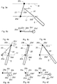
- Figures 4a to 4f are schematic representations of different drilling situations from the top and correspondingly as projections shown on a display in accordance with the invention.
- Figure 4a is a schematic representation of a situation, in which the planned hole 20 runs from the navigation plane 17 to the base plane 18. Its starting point 20a and correspondingly end point 20b are shown as circles on the planes.
- the feed device 5 is directed so that the starting point 20a' of the actual hole 20' is at a distance s from the starting point 20a of the planned hole. Similarly, the direction of the actual hole is at a different angle with respect to the navigation plane.
- the situation is presented as a projection on the navigation plane 17, which in this case serves as the projection plane.
- the planned hole 20 is shown as a continuous line with the starting point 20a at one end and the end point 20b on the base plane at the other end.
- the projection of the planned hole on the navigation plane 17 is shown as a line segment 20c between them.
- the starting point 20a' of the actual hole to be drilled is marked with a circle and the length of the hole as a projection 20c' as a continuous line segment.
- Figure 4c shows a situation, in which the planned hole and the hole to be drilled are parallel to each other, but at a distance from each other.
- This situation is displayed in Figure 4d in such a manner that the line segments 20c and 20c' representing the lengths of the planned and actual holes are the same, but the starting points 20a and 20a' and, respectively, end points 20b and 20b' of the holes have shifted in relation to each other, which indicates a transverse shift of the hole.
- the end 20b' of the actual hole is, however, as desired on the base plane 18, and therefore, the hole is acceptable.
- Figures 4e and 4f show a situation, in which the directions of the planned hole and actual hole to be drilled differ from each other so that in reality the hole to be drilled differs from the normal of the navigation plane 17 more than the planned hole.
- a hole having the length of the planned hole were drilled, a distance x would remain between the end 20b of the formed hole and the base plane 18.
- the user notices that the originally planned hole length is not enough and the hole length needs to be increased. This way, the actual drilled hole is made to extend to the base plane 18 and, thus, to a required location for blasting.
- Figures 4b, 4d, and 4f the symbols of the planned hole and actual hole are shown on top of each other in elevation so as to distinguish them better from each other. In theory, they should be on the same line, if they are at the same location in elevation. In practice, they are shown to be at the same location, but different colours or line segments are used for them so as to distinguish them from each other.
- the symbols representing the starting and end points of the holes may be freely selected. Similarly, different line segment types and thicknesses may be selected as required as long as the result is clear to the user and easily viewable.
- the figures also show the base plane intersections of the hole to be created or its extension and the planned hole on a diamond 20b".
- the invention is described by way of example only and is not in any way restricted to them.
- the essential thing is that when projecting the position of a hole to be drilled, the position of its end point formed on the basis of its planned length relative to the base plane of the round is presented in such a manner that the user sees from the projection, whether the end point of the hole to be drilled is on the base plane or whether it differs to either side of the base plane, so that the user may, if necessary, correct the drilling to correspond to the desired target, that is, ending the hole on the base plane.
- the projection plane may be any transverse plane to the longitudinal direction of the round, on which different projections may be defined.
- the projection plane is most preferably essentially perpendicular to the longitudinal direction of the round and thus also to the longitudinal direction of most of the holes. Because all holes are not parallel, it cannot be perpendicular to the longitudinal direction of all holes.
- the projection plane may be the earlier mentioned navigation plane, but it may also differ from it and be non-parallel to it. Similarly, the starting points of the holes need not be on the projection plane.
- the plane extending through the planned end point of the hole is used for each hole, and all these planes are parallel to the base plane of the round. They may be the same as the base plane of the round or they may be at a distance from it depending on the end point of the hole. In practice, in most cases the base plane of parallel holes in the middle of the round is the same as the base plane of the round, but on the edges and in cutholes, the base plane differs from the base plane of the round.
Landscapes
- Engineering & Computer Science (AREA)
- Mining & Mineral Resources (AREA)
- Life Sciences & Earth Sciences (AREA)
- Geology (AREA)
- Environmental & Geological Engineering (AREA)
- General Life Sciences & Earth Sciences (AREA)
- Geochemistry & Mineralogy (AREA)
- Physics & Mathematics (AREA)
- Fluid Mechanics (AREA)
- Earth Drilling (AREA)
Claims (13)
- Verfahren zum Anzeigen schräg verlaufender Löcher (20), die beim Bohren von Löchern (20) mit einem Gesteinsbohrgerät (1), das eine Steuereinrichtung (11) und eine dazu gehörige Anzeige und Messmittel zum Definieren der Richtung und der Position der Bohrstange (9) unter Verwendung eines vorab entworfenen Bohrplans (16), der unter Verwendung eines dreidimensionalen Satzes von Koordinaten in Bezug auf das Gestein (10) definiert ist und für jedes Loch (20) das gebohrt werden soll, einen Anfangspunkt (20a) und einen Endpunkt (20b) gemäß einer Richtung jedes geplanten Lochs (20) definiert, aufweist, in Gestein (10) gebohrt werden sollen, wobei bei dem Verfahren für das Bohren eines Lochs (20) an der Anzeige der Steuereinrichtung (11) eine Projektion (20c) gemäß dem Bohrplan (16) des geplanten Lochs (20) auf einer quer verlaufenden Projektionsebene der zu bohrenden Löcher (20), und eine Projektion des Lochs (20'), das erzeugt wird, wenn gemäß der gegenwärtigen Position der Bohrstange (9) auf der Projektionsebene gemäß einer für das Loch (20) festgelegten Ziellänge gebohrt wird, angezeigt wird, gekennzeichnet durchb) Definieren, für jedes Loch (20), einer Basisebene (18), die durch den Endpunkt (20b) des Lochs (20) und parallel zu der Projektionsebene verläuft, undc) alternatives Anzeigen einer Projektion des Schnittpunkts zwischen dem Loch (20'), das erzeugt wird, wenn gemäß der gegenwärtigen Position der Bohrstange (9) gebohrt wird, und der definierten Basisebene (18) auf der Projektionsebene, falls sich das Loch (20') zu der Basisebene (18) erstreckt, oder einer Projektion des Schnittpunkts zwischen einer Verlängerung des Lochs (20'), das erzeugt wird, wenn gemäß der gegenwärtigen Position der Bohrstange (9) gebohrt wird, und der definierten Basisebene (18) auf der Projektionsebene, falls sich das Loch (20') nicht zu der Basisebene (18) erstreckt, mit einem graphischen Ortsymbol.
- Verfahren nach Anspruch 1, gekennzeichnet durch Richten der Bohrstange (9), bis sich der Endpunkt (20b) des geplanten Lochs (20) und das Symbol des Schnittpunkts der Basisebene (18) des Lochs (20') das erzeugt werden soll, und des geplanten Lochs (20) auf der Anzeige übereinander befinden, wenn der Schnittpunkt der Projektion des Lochs (20'), das während des Bohrens erzeugt wird, oder seine parallele Verlängerung und die Basisebene (18) von dem Endpunkt (20b) des geplanten Lochs (20) abweichen.
- Verfahren nach Anspruch 2, gekennzeichnet durch derartiges Ändern der Bohrlänge des Lochs (20'), das während des Bohrens erzeugt werden soll, dass seine Projektion (20c') auf der Anzeige an dem Schnittpunkt endet, wenn sich der Endpunkt (20b') der Projektion (20c') des Lochs (20'), das während des Bohrens erzeugt wird, nach dem Richten nicht an dem gleichen Punkt wie der Endpunkt (20b) des geplanten Lochs (20) befindet.
- Verfahren nach einem der Ansprüche 1 bis 3, gekennzeichnet durch Definieren eines graphischen Ortsymbols an dem Endpunkt (20b) des geplanten Lochs (20).
- Verfahren nach Anspruch 4, gekennzeichnet durch Verwenden von Symbolen mit einer ähnlichen Form und Größe als die graphischen Ortssymbole, die an dem Endpunkt (20b) des geplanten Lochs (20) und an dem Schnittpunkt des Lochs (20') oder seiner Verlängerung, das oder die während des Bohrens erzeugt wird, und der definierten Basisebene (18) definiert sind.
- Verfahren nach einem der vorhergehenden Ansprüche, gekennzeichnet durch Zeigen der Projektion des Liniensegments zwischen den Punkten als Liniensegment, das sich von dem das tatsächliche Loch (20') darstellenden Liniensegment unterscheidet, wenn sich der Endpunkt (20b') des Lochs (20), das erzeugt wird, wenn gemäß der gegenwärtigen Stelle der Bohrstange (9) gebohrt wird, in einer Entfernung von dem Schnittpunkt der Verlängerung des Lochs (20') und der Basisebene (18) befindet.
- Verfahren nach einem der Ansprüche 1 bis 5, gekennzeichnet durch automatisches Ändern der Richtung und der Länge des Lochs (20'), das während des Bohrens erzeugt wird, auf eine solche Weise, dass die Basisebene (18) des Lochs (20), das in dem Bohrplan (16) geplant ist, erreicht wird.
- Verfahren nach einem der Ansprüche 1 bis 7, gekennzeichnet durch Verwenden einer gemeinsamen Navigationsebene (17), in der die Ausgangspunkte (20a) aller Löcher (20) definiert sind, als die Projektionsebene für alle Löcher (20) in dem Bohrplan (16).
- Einrichtung in Verbindung mit einem Gesteinsbohrgerät (1) zum Anzeigen schräg verlaufender Bohrlöcher (20), wenn mit dem Gesteinsbohrgerät (1), das eine Steuereinrichtung (11) und eine dazu gehörige Anzeige und Messmittel zum Definieren der Richtung und der Position der Bohrstange (9) unter Verwendung eines vorab entworfenen Bohrplans (16), der unter Verwendung eines dreidimensionalen Satzes von Koordinaten in Bezug auf das Gestein (10) definiert ist und für jedes Loch (20) das gebohrt werden soll, in dem Koordinatensystem einen Anfangspunkt (20a) und einen Endpunkt (20b) gemäß der geplanten Richtung und Länge jedes Lochs (20) definiert, und Anzeigemittel zum Anzeigen einer Projektion (20c) des geplanten Lochs (20) als Liniensegment auf der quer verlaufenden Projektionsebene der Löcher (20) und, entsprechend, einer Projektion (20c') des tatsächlichen Lochs (20'), das erzeugt wird, wenn gemäß der gegenwärtigen Position der Bohrstange (9) gebohrt wird, als Liniensegment auf der Projektionsebene, wenn gemäß einer Ziellänge, die für das Loch (20) festgelegt ist, gebohrt wird, an der Anzeige der Steuereinrichtung (11) aufweist, Löcher (20) in Gestein (10) gebohrt werden, dadurch gekennzeichnet, dass die Anzeigemittel dazu eingerichtet sind,b) für jedes Loch (20) eine Basisebene (18), die durch den Endpunkt (20b) des Lochs (20) und parallel zu der Projektionsebene verläuft, zu definieren,c) mit einem graphischen Ortssymbol in der Projektion alternativ den Schnittpunkt zwischen dem Loch (20'), das erzeugt wird, wenn gemäß der gegenwärtigen Position der Bohrstange (9) gebohrt wird, und der Basisebene (18), die für das Loch (20) definiert ist, anzuzeigen, falls sich das Loch (20') zu der Basisebene (18) erstreckt, oder den Schnittpunkt zwischen einer Verlängerung des Lochs (20'), das erzeugt wird, wenn gemäß der gegenwärtigen Position der Bohrstange (9) gebohrt wird, und der für das Loch (20) definierten Basisebene (18) anzuzeigen, falls sich das Loch (20') nicht zu der Basisebene (18) erstreckt.
- Einrichtung nach Anspruch 9, dadurch gekennzeichnet, dass die Anzeigemittel dazu eingerichtet sind, an dem Endpunkt (20b) des geplanten Lochs (20) ein graphisches Ortssymbol anzuzeigen.
- Einrichtung nach Anspruch 10, dadurch gekennzeichnet, dass die Anzeigemittel dazu eingerichtet sind, Symbole mit einer ähnlichen Form und Größe als die graphischen Ortssymbole für den Endpunkt (20b) des geplanten Lochs (20) und für den Basisebenen-Schnittpunkt des Lochs (20') oder seiner Verlängerung, das oder die während des Bohrens erzeugt wird, und der definierten Basisebene (18) anzuzeigen.
- Einrichtung nach einem der Ansprüche 9 bis 11, dadurch gekennzeichnet, dass die Anzeigemittel dann, wenn gemäß der gegenwärtigen Stelle der Bohrstange (9) gebohrt wird und wenn sich der Endpunkt (20b') des Lochs (20'), das während des Bohrens erzeugt werden soll, in einer Entfernung von dem Schnittpunkt der Lochverlängerung und der Basisebene (18) befindet, dazu eingerichtet sind, die Projektion des Liniensegments zwischen den Punkten als Liniensegment, das sich von dem das tatsächliche Loch (20') darstellenden Liniensegment unterscheidet, darzustellen.
- Einrichtung nach einem der Ansprüche 9 bis 12, dadurch gekennzeichnet, dass die Anzeigemittel dazu eingerichtet sind, eine gemeinsame Navigationsebene (17), in der die Ausgangspunkte (20a) aller Löcher (20) definiert sind, als die Projektionsebene für alle Löcher (20) in dem Bohrplan (16) zu verwenden.
Applications Claiming Priority (2)
| Application Number | Priority Date | Filing Date | Title |
|---|---|---|---|
| FI20085587A FI121436B (fi) | 2008-06-13 | 2008-06-13 | Menetelmä ja laitteisto porattavien reikien esittämiseksi ja poratangon suuntaamiseksi porattaessa reikiä kallioon |
| PCT/FI2009/050468 WO2009150294A1 (en) | 2008-06-13 | 2009-06-03 | Method and equipment for displaying drill holes and method for directing drill rod when holes are drilled into rock |
Publications (3)
| Publication Number | Publication Date |
|---|---|
| EP2307657A1 EP2307657A1 (de) | 2011-04-13 |
| EP2307657A4 EP2307657A4 (de) | 2016-02-17 |
| EP2307657B1 true EP2307657B1 (de) | 2017-09-20 |
Family
ID=39589350
Family Applications (1)
| Application Number | Title | Priority Date | Filing Date |
|---|---|---|---|
| EP09761849.0A Active EP2307657B1 (de) | 2008-06-13 | 2009-06-03 | Verfahren und einrichtung zur anzeige von bohrlöchern und verfahrne lenken einer bohrstange beim bohren von löchern in gestein |
Country Status (9)
| Country | Link |
|---|---|
| US (1) | US8689902B2 (de) |
| EP (1) | EP2307657B1 (de) |
| JP (1) | JP5492880B2 (de) |
| CN (1) | CN102066687B (de) |
| AU (1) | AU2009256481B2 (de) |
| CA (1) | CA2726930C (de) |
| FI (1) | FI121436B (de) |
| WO (1) | WO2009150294A1 (de) |
| ZA (1) | ZA201100281B (de) |
Families Citing this family (14)
| Publication number | Priority date | Publication date | Assignee | Title |
|---|---|---|---|---|
| FI124168B (fi) | 2011-06-14 | 2014-04-15 | Sandvik Mining & Constr Oy | Menetelmä panostussuunnitelman laatimiseksi |
| FI124169B (fi) * | 2011-06-14 | 2014-04-15 | Sandvik Mining & Constr Oy | Menetelmä poraussuunnitelman laatimiseksi |
| CN102493797B (zh) * | 2011-11-23 | 2015-07-22 | 中联重科股份有限公司 | 远程监控终端、工法决策系统及方法以及旋挖钻机 |
| EP2672057B1 (de) | 2012-06-07 | 2017-08-16 | Sandvik Mining and Construction Oy | Dynamischer Arbeitsbereich |
| EP2698498A1 (de) * | 2012-08-17 | 2014-02-19 | Sandvik Mining and Construction Oy | Verfahren, Felsenbohranlage und Steuerungsvorrichtung |
| EP2994613B1 (de) * | 2013-05-08 | 2017-06-28 | Sandvik Mining and Construction Oy | Anordnung zum zuweisen und bohren von bohrlöchern |
| WO2015090362A1 (en) * | 2013-12-17 | 2015-06-25 | Sandvik Mining And Construction Oy | Arrangement and method of utilizing rock drilling information |
| CN104400914B (zh) * | 2014-09-26 | 2016-09-28 | 重庆大学 | 一种在小直径深孔中实现侧向钻盲孔的装置 |
| SE541052C2 (sv) * | 2015-09-30 | 2019-03-19 | Epiroc Rock Drills Ab | System och förfarande för borrplansgenerering, borrigg, datorprogram samt datorprogramprodukt |
| CN109403946B (zh) * | 2018-12-27 | 2022-07-29 | 北京三一智造科技有限公司 | 旋挖钻机回转动画显示的方法、装置及旋挖钻机 |
| JP7609443B2 (ja) * | 2019-12-30 | 2025-01-07 | 公立大学法人公立諏訪東京理科大学 | 穿孔装置 |
| CN111594143A (zh) * | 2020-05-25 | 2020-08-28 | 贵州盘江精煤股份有限公司 | 一种快速确定钻孔方位角的施工方法 |
| CN120813751A (zh) * | 2023-03-22 | 2025-10-17 | 安百拓凿岩有限公司 | 用于在钻孔操作中对准进给梁的方法、控制节点和计算机程序 |
| EP4684094A1 (de) * | 2023-03-22 | 2026-01-28 | Epiroc Rock Drills Aktiebolag | Verfahren, steuerknoten und computerprogramm zum ausrichten eines vorschubbalkens in einem nachbohrvorgang |
Family Cites Families (14)
| Publication number | Priority date | Publication date | Assignee | Title |
|---|---|---|---|---|
| JPS5524237Y2 (de) * | 1975-07-25 | 1980-06-10 | ||
| JPS5415403A (en) * | 1977-06-07 | 1979-02-05 | Toyo Kogyo Co | Bore adjusting apparatus of boring machine |
| JPS60199194A (ja) * | 1984-03-24 | 1985-10-08 | マツダ株式会社 | さく孔方法 |
| FI79884C (fi) * | 1988-06-03 | 1990-03-12 | Tampella Oy Ab | Foerfarande och anordning foer borrning av ett haol i berg. |
| KR970007384B1 (en) * | 1994-07-13 | 1997-05-08 | Sunkyong Const Co | Method for excavating a working face |
| DE4445420C1 (de) * | 1994-12-20 | 1995-11-02 | Kali & Salz Ag | Verfahren zum verbesserten programmierten Sprenglochbohren beim Auffahren von Strecken im Berg- und Tunnelbau |
| JPH1096627A (ja) * | 1996-09-25 | 1998-04-14 | Furukawa Co Ltd | さく孔装置の表示装置 |
| FI105942B (fi) * | 1997-06-09 | 2000-10-31 | Tamrock Oy | Menetelmä kallionporauksen ohjaamiseksi |
| FI111287B (fi) * | 1998-12-10 | 2003-06-30 | Tamrock Oy | Menetelmä ja kallionporauslaite kallionporauksen ohjaamiseksi |
| FI115481B (fi) * | 2001-12-03 | 2005-05-13 | Sandvik Tamrock Oy | Järjestely porauksen ohjaukseen |
| JP2005344418A (ja) * | 2004-06-04 | 2005-12-15 | Mac Kk | トンネル工事現場用総合管理システム |
| FI118052B (fi) * | 2005-06-27 | 2007-06-15 | Sandvik Tamrock Oy | Menetelmä ja ohjelmistotuote porausyksikön paikoittamiseksi sekä kallionporauslaite |
| FI119263B (fi) * | 2005-08-30 | 2008-09-15 | Sandvik Tamrock Oy | Adaptiivinen käyttöliittymä kallionporauslaitteelle |
| FI123153B (fi) * | 2006-12-22 | 2012-11-30 | Sandvik Mining & Construction Oy | Porauskaavion laatiminen kalliotilan louhimista varten |
-
2008
- 2008-06-13 FI FI20085587A patent/FI121436B/fi active IP Right Grant
-
2009
- 2009-06-03 WO PCT/FI2009/050468 patent/WO2009150294A1/en not_active Ceased
- 2009-06-03 CN CN200980122214.3A patent/CN102066687B/zh not_active Expired - Fee Related
- 2009-06-03 EP EP09761849.0A patent/EP2307657B1/de active Active
- 2009-06-03 JP JP2011513011A patent/JP5492880B2/ja not_active Expired - Fee Related
- 2009-06-03 US US12/997,456 patent/US8689902B2/en not_active Expired - Fee Related
- 2009-06-03 CA CA2726930A patent/CA2726930C/en active Active
- 2009-06-03 AU AU2009256481A patent/AU2009256481B2/en not_active Ceased
-
2011
- 2011-01-11 ZA ZA2011/00281A patent/ZA201100281B/en unknown
Non-Patent Citations (1)
| Title |
|---|
| None * |
Also Published As
| Publication number | Publication date |
|---|---|
| FI121436B (fi) | 2010-11-15 |
| EP2307657A1 (de) | 2011-04-13 |
| US20110100711A1 (en) | 2011-05-05 |
| JP2011522983A (ja) | 2011-08-04 |
| ZA201100281B (en) | 2011-10-26 |
| AU2009256481B2 (en) | 2012-04-12 |
| AU2009256481A1 (en) | 2009-12-17 |
| WO2009150294A1 (en) | 2009-12-17 |
| US8689902B2 (en) | 2014-04-08 |
| FI20085587L (fi) | 2009-12-14 |
| FI20085587A0 (fi) | 2008-06-13 |
| CA2726930A1 (en) | 2009-12-17 |
| CN102066687B (zh) | 2014-11-26 |
| EP2307657A4 (de) | 2016-02-17 |
| CA2726930C (en) | 2015-05-12 |
| JP5492880B2 (ja) | 2014-05-14 |
| CN102066687A (zh) | 2011-05-18 |
Similar Documents
| Publication | Publication Date | Title |
|---|---|---|
| US8689902B2 (en) | Method and equipment for displaying drill holes and method for directing drill rod when holes are drilled into rock | |
| CA2916148C (en) | Arrangement for controlling percussive drilling process | |
| JP5037678B2 (ja) | 曲線トンネルにおける穿孔パターン配向方法、岩盤掘削装置およびソフトウェア製品 | |
| EP2137376B1 (de) | Verfahren zur änderung von bohrschablonen, gesteinsbohrgestell und softwareprodukt | |
| EP2721240B1 (de) | Verfahren und anordnung zur konzeption eines bohrungsplans | |
| EP2721241B1 (de) | Verfahren und anordnung zur erstellung eines ladeplans | |
| CN102791958B (zh) | 用于呈现定位信息的方法、用户接口和岩石钻探装备 | |
| CN105164372A (zh) | 分配并凿钻钻孔的设备 | |
| US20080230270A1 (en) | Arrangement for Positioning Rock Drilling Rig on Drilling Site | |
| WO2004055325A1 (en) | Drilling head position display | |
| WO2003025341A1 (en) | Method for automatic generation of a drill pattern | |
| AU2002334545A1 (en) | Method for automatic generation of a drill pattern | |
| AT525280A4 (de) | Verfahren zur Steuerung einer Horizontalbohranlage |
Legal Events
| Date | Code | Title | Description |
|---|---|---|---|
| PUAI | Public reference made under article 153(3) epc to a published international application that has entered the european phase |
Free format text: ORIGINAL CODE: 0009012 |
|
| 17P | Request for examination filed |
Effective date: 20101221 |
|
| AK | Designated contracting states |
Kind code of ref document: A1 Designated state(s): AT BE BG CH CY CZ DE DK EE ES FI FR GB GR HR HU IE IS IT LI LT LU LV MC MK MT NL NO PL PT RO SE SI SK TR |
|
| AX | Request for extension of the european patent |
Extension state: AL BA RS |
|
| DAX | Request for extension of the european patent (deleted) | ||
| RA4 | Supplementary search report drawn up and despatched (corrected) |
Effective date: 20160120 |
|
| RIC1 | Information provided on ipc code assigned before grant |
Ipc: E21D 9/00 20060101ALI20160112BHEP Ipc: E21B 7/02 20060101AFI20160112BHEP Ipc: E21B 44/00 20060101ALI20160112BHEP |
|
| GRAP | Despatch of communication of intention to grant a patent |
Free format text: ORIGINAL CODE: EPIDOSNIGR1 |
|
| INTG | Intention to grant announced |
Effective date: 20170301 |
|
| RIN1 | Information on inventor provided before grant (corrected) |
Inventor name: PUURA, JUSSI Inventor name: MUONA, JOUKO Inventor name: LAINE, PEKKA Inventor name: SAELENIEMI, TOMMI Inventor name: SAARELA, MARKUS Inventor name: KOIVUNEN, PERTTI Inventor name: OSARA, JUKKA Inventor name: HAUTALA, TATU |
|
| GRAS | Grant fee paid |
Free format text: ORIGINAL CODE: EPIDOSNIGR3 |
|
| GRAA | (expected) grant |
Free format text: ORIGINAL CODE: 0009210 |
|
| AK | Designated contracting states |
Kind code of ref document: B1 Designated state(s): AT BE BG CH CY CZ DE DK EE ES FI FR GB GR HR HU IE IS IT LI LT LU LV MC MK MT NL NO PL PT RO SE SI SK TR |
|
| REG | Reference to a national code |
Ref country code: GB Ref legal event code: FG4D |
|
| REG | Reference to a national code |
Ref country code: CH Ref legal event code: EP |
|
| REG | Reference to a national code |
Ref country code: AT Ref legal event code: REF Ref document number: 930278 Country of ref document: AT Kind code of ref document: T Effective date: 20171015 |
|
| REG | Reference to a national code |
Ref country code: IE Ref legal event code: FG4D |
|
| REG | Reference to a national code |
Ref country code: SE Ref legal event code: TRGR |
|
| REG | Reference to a national code |
Ref country code: DE Ref legal event code: R096 Ref document number: 602009048454 Country of ref document: DE |
|
| REG | Reference to a national code |
Ref country code: NO Ref legal event code: T2 Effective date: 20170920 |
|
| REG | Reference to a national code |
Ref country code: NL Ref legal event code: MP Effective date: 20170920 |
|
| PG25 | Lapsed in a contracting state [announced via postgrant information from national office to epo] |
Ref country code: HR Free format text: LAPSE BECAUSE OF FAILURE TO SUBMIT A TRANSLATION OF THE DESCRIPTION OR TO PAY THE FEE WITHIN THE PRESCRIBED TIME-LIMIT Effective date: 20170920 Ref country code: FI Free format text: LAPSE BECAUSE OF FAILURE TO SUBMIT A TRANSLATION OF THE DESCRIPTION OR TO PAY THE FEE WITHIN THE PRESCRIBED TIME-LIMIT Effective date: 20170920 Ref country code: LT Free format text: LAPSE BECAUSE OF FAILURE TO SUBMIT A TRANSLATION OF THE DESCRIPTION OR TO PAY THE FEE WITHIN THE PRESCRIBED TIME-LIMIT Effective date: 20170920 |
|
| REG | Reference to a national code |
Ref country code: LT Ref legal event code: MG4D |
|
| REG | Reference to a national code |
Ref country code: AT Ref legal event code: MK05 Ref document number: 930278 Country of ref document: AT Kind code of ref document: T Effective date: 20170920 |
|
| PG25 | Lapsed in a contracting state [announced via postgrant information from national office to epo] |
Ref country code: GR Free format text: LAPSE BECAUSE OF FAILURE TO SUBMIT A TRANSLATION OF THE DESCRIPTION OR TO PAY THE FEE WITHIN THE PRESCRIBED TIME-LIMIT Effective date: 20171221 Ref country code: LV Free format text: LAPSE BECAUSE OF FAILURE TO SUBMIT A TRANSLATION OF THE DESCRIPTION OR TO PAY THE FEE WITHIN THE PRESCRIBED TIME-LIMIT Effective date: 20170920 Ref country code: BG Free format text: LAPSE BECAUSE OF FAILURE TO SUBMIT A TRANSLATION OF THE DESCRIPTION OR TO PAY THE FEE WITHIN THE PRESCRIBED TIME-LIMIT Effective date: 20171220 |
|
| PG25 | Lapsed in a contracting state [announced via postgrant information from national office to epo] |
Ref country code: NL Free format text: LAPSE BECAUSE OF FAILURE TO SUBMIT A TRANSLATION OF THE DESCRIPTION OR TO PAY THE FEE WITHIN THE PRESCRIBED TIME-LIMIT Effective date: 20170920 |
|
| PG25 | Lapsed in a contracting state [announced via postgrant information from national office to epo] |
Ref country code: ES Free format text: LAPSE BECAUSE OF FAILURE TO SUBMIT A TRANSLATION OF THE DESCRIPTION OR TO PAY THE FEE WITHIN THE PRESCRIBED TIME-LIMIT Effective date: 20170920 Ref country code: CZ Free format text: LAPSE BECAUSE OF FAILURE TO SUBMIT A TRANSLATION OF THE DESCRIPTION OR TO PAY THE FEE WITHIN THE PRESCRIBED TIME-LIMIT Effective date: 20170920 Ref country code: RO Free format text: LAPSE BECAUSE OF FAILURE TO SUBMIT A TRANSLATION OF THE DESCRIPTION OR TO PAY THE FEE WITHIN THE PRESCRIBED TIME-LIMIT Effective date: 20170920 Ref country code: PL Free format text: LAPSE BECAUSE OF FAILURE TO SUBMIT A TRANSLATION OF THE DESCRIPTION OR TO PAY THE FEE WITHIN THE PRESCRIBED TIME-LIMIT Effective date: 20170920 |
|
| REG | Reference to a national code |
Ref country code: FR Ref legal event code: PLFP Year of fee payment: 10 |
|
| PG25 | Lapsed in a contracting state [announced via postgrant information from national office to epo] |
Ref country code: IS Free format text: LAPSE BECAUSE OF FAILURE TO SUBMIT A TRANSLATION OF THE DESCRIPTION OR TO PAY THE FEE WITHIN THE PRESCRIBED TIME-LIMIT Effective date: 20180120 Ref country code: IT Free format text: LAPSE BECAUSE OF FAILURE TO SUBMIT A TRANSLATION OF THE DESCRIPTION OR TO PAY THE FEE WITHIN THE PRESCRIBED TIME-LIMIT Effective date: 20170920 Ref country code: SK Free format text: LAPSE BECAUSE OF FAILURE TO SUBMIT A TRANSLATION OF THE DESCRIPTION OR TO PAY THE FEE WITHIN THE PRESCRIBED TIME-LIMIT Effective date: 20170920 Ref country code: EE Free format text: LAPSE BECAUSE OF FAILURE TO SUBMIT A TRANSLATION OF THE DESCRIPTION OR TO PAY THE FEE WITHIN THE PRESCRIBED TIME-LIMIT Effective date: 20170920 Ref country code: AT Free format text: LAPSE BECAUSE OF FAILURE TO SUBMIT A TRANSLATION OF THE DESCRIPTION OR TO PAY THE FEE WITHIN THE PRESCRIBED TIME-LIMIT Effective date: 20170920 |
|
| REG | Reference to a national code |
Ref country code: DE Ref legal event code: R097 Ref document number: 602009048454 Country of ref document: DE |
|
| PLBE | No opposition filed within time limit |
Free format text: ORIGINAL CODE: 0009261 |
|
| STAA | Information on the status of an ep patent application or granted ep patent |
Free format text: STATUS: NO OPPOSITION FILED WITHIN TIME LIMIT |
|
| PG25 | Lapsed in a contracting state [announced via postgrant information from national office to epo] |
Ref country code: DK Free format text: LAPSE BECAUSE OF FAILURE TO SUBMIT A TRANSLATION OF THE DESCRIPTION OR TO PAY THE FEE WITHIN THE PRESCRIBED TIME-LIMIT Effective date: 20170920 |
|
| 26N | No opposition filed |
Effective date: 20180621 |
|
| PG25 | Lapsed in a contracting state [announced via postgrant information from national office to epo] |
Ref country code: SI Free format text: LAPSE BECAUSE OF FAILURE TO SUBMIT A TRANSLATION OF THE DESCRIPTION OR TO PAY THE FEE WITHIN THE PRESCRIBED TIME-LIMIT Effective date: 20170920 |
|
| REG | Reference to a national code |
Ref country code: DE Ref legal event code: R119 Ref document number: 602009048454 Country of ref document: DE |
|
| REG | Reference to a national code |
Ref country code: CH Ref legal event code: PL |
|
| GBPC | Gb: european patent ceased through non-payment of renewal fee |
Effective date: 20180603 |
|
| REG | Reference to a national code |
Ref country code: BE Ref legal event code: MM Effective date: 20180630 |
|
| REG | Reference to a national code |
Ref country code: IE Ref legal event code: MM4A |
|
| PG25 | Lapsed in a contracting state [announced via postgrant information from national office to epo] |
Ref country code: LU Free format text: LAPSE BECAUSE OF NON-PAYMENT OF DUE FEES Effective date: 20180603 Ref country code: MC Free format text: LAPSE BECAUSE OF FAILURE TO SUBMIT A TRANSLATION OF THE DESCRIPTION OR TO PAY THE FEE WITHIN THE PRESCRIBED TIME-LIMIT Effective date: 20170920 |
|
| PG25 | Lapsed in a contracting state [announced via postgrant information from national office to epo] |
Ref country code: GB Free format text: LAPSE BECAUSE OF NON-PAYMENT OF DUE FEES Effective date: 20180603 Ref country code: LI Free format text: LAPSE BECAUSE OF NON-PAYMENT OF DUE FEES Effective date: 20180630 Ref country code: CH Free format text: LAPSE BECAUSE OF NON-PAYMENT OF DUE FEES Effective date: 20180630 Ref country code: DE Free format text: LAPSE BECAUSE OF NON-PAYMENT OF DUE FEES Effective date: 20190101 Ref country code: IE Free format text: LAPSE BECAUSE OF NON-PAYMENT OF DUE FEES Effective date: 20180603 |
|
| PG25 | Lapsed in a contracting state [announced via postgrant information from national office to epo] |
Ref country code: BE Free format text: LAPSE BECAUSE OF NON-PAYMENT OF DUE FEES Effective date: 20180630 |
|
| PG25 | Lapsed in a contracting state [announced via postgrant information from national office to epo] |
Ref country code: MT Free format text: LAPSE BECAUSE OF NON-PAYMENT OF DUE FEES Effective date: 20180603 |
|
| PG25 | Lapsed in a contracting state [announced via postgrant information from national office to epo] |
Ref country code: TR Free format text: LAPSE BECAUSE OF FAILURE TO SUBMIT A TRANSLATION OF THE DESCRIPTION OR TO PAY THE FEE WITHIN THE PRESCRIBED TIME-LIMIT Effective date: 20170920 |
|
| PG25 | Lapsed in a contracting state [announced via postgrant information from national office to epo] |
Ref country code: PT Free format text: LAPSE BECAUSE OF FAILURE TO SUBMIT A TRANSLATION OF THE DESCRIPTION OR TO PAY THE FEE WITHIN THE PRESCRIBED TIME-LIMIT Effective date: 20170920 Ref country code: HU Free format text: LAPSE BECAUSE OF FAILURE TO SUBMIT A TRANSLATION OF THE DESCRIPTION OR TO PAY THE FEE WITHIN THE PRESCRIBED TIME-LIMIT; INVALID AB INITIO Effective date: 20090603 |
|
| PG25 | Lapsed in a contracting state [announced via postgrant information from national office to epo] |
Ref country code: CY Free format text: LAPSE BECAUSE OF FAILURE TO SUBMIT A TRANSLATION OF THE DESCRIPTION OR TO PAY THE FEE WITHIN THE PRESCRIBED TIME-LIMIT Effective date: 20170920 Ref country code: MK Free format text: LAPSE BECAUSE OF NON-PAYMENT OF DUE FEES Effective date: 20170920 |
|
| PGFP | Annual fee paid to national office [announced via postgrant information from national office to epo] |
Ref country code: FR Payment date: 20220523 Year of fee payment: 14 |
|
| PGFP | Annual fee paid to national office [announced via postgrant information from national office to epo] |
Ref country code: NO Payment date: 20230608 Year of fee payment: 15 |
|
| PG25 | Lapsed in a contracting state [announced via postgrant information from national office to epo] |
Ref country code: FR Free format text: LAPSE BECAUSE OF NON-PAYMENT OF DUE FEES Effective date: 20230630 |
|
| PG25 | Lapsed in a contracting state [announced via postgrant information from national office to epo] |
Ref country code: NO Free format text: LAPSE BECAUSE OF NON-PAYMENT OF DUE FEES Effective date: 20240630 |
|
| PGFP | Annual fee paid to national office [announced via postgrant information from national office to epo] |
Ref country code: SE Payment date: 20250429 Year of fee payment: 17 |