EP2307262B1 - Bodenplatte für ein fahrzeug - Google Patents
Bodenplatte für ein fahrzeug Download PDFInfo
- Publication number
- EP2307262B1 EP2307262B1 EP09790144.1A EP09790144A EP2307262B1 EP 2307262 B1 EP2307262 B1 EP 2307262B1 EP 09790144 A EP09790144 A EP 09790144A EP 2307262 B1 EP2307262 B1 EP 2307262B1
- Authority
- EP
- European Patent Office
- Prior art keywords
- vehicle
- foot
- recess
- floorboard
- operator
- Prior art date
- Legal status (The legal status is an assumption and is not a legal conclusion. Google has not performed a legal analysis and makes no representation as to the accuracy of the status listed.)
- Not-in-force
Links
Images




Classifications
-
- B—PERFORMING OPERATIONS; TRANSPORTING
- B62—LAND VEHICLES FOR TRAVELLING OTHERWISE THAN ON RAILS
- B62D—MOTOR VEHICLES; TRAILERS
- B62D25/00—Superstructure or monocoque structure sub-units; Parts or details thereof not otherwise provided for
- B62D25/20—Floors or bottom sub-units
Definitions
- the present invention relates generally to a vehicle and in particular to a utility vehicle having foot controlled pedals.
- Utility vehicles are known.
- the present disclosure relates to vehicles, including utility vehicles.
- the present disclosure relates to utility vehicles having foot controlled pedals.
- the present disclosure relates to a floorboard for use with utility vehicles, and particularly for those with foot controlled pedals.
- a utility vehicle comprising a vehicle frame, a prime mover attached to the frame, wheels supporting the frame, a floorboard, and a foot control adjacent the floor board, the floorboard having a plurality of contact points for contacting an operator's foot when operating the foot control.
- a vehicle comprises a vehicle frame, a prime mover attached to the frame, wheels supporting the frame and driven by the prime mover, a floorboard, and a foot control adjacent the floor board, the floorboard having a recess for receiving the heel of an operator's foot when operating the foot control.
- a vehicle comprises a vehicle frame, a prime mover attached to the frame, wheels supporting the frame and driven by the prime mover, a floorboard, and a plurality of foot controls adjacent the floor board.
- the floorboard has a groove laterally flanking the plurality of foot controls, the groove being profiled to define a location for the heel of an operator's foot when operating the plurality of foot controls.
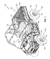
- FIG. 1 is a perspective view of an exemplary utility vehicle
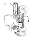
- FIG. 2 illustrates a left side view of the exemplary utility vehicle of FIG. 1 ;
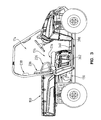
- FIG. 3 illustrates a right side view of the exemplary utility vehicle of FIG. 1 ;
- FIG. 4 illustrates a top view of the utility exemplary vehicle of FIG. 1 ;
- FIG. 5 illustrates a perspective view of the utility vehicle of FIG. 1 with a cargo bed removed;
- FIG. 6 illustrates a perspective view of the seating and floor body panel
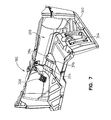
- FIG. 7 illustrates a guard member provided as part of the floor body panel
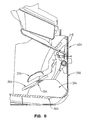
- FIG. 8 illustrates a cross-section of the floor body panel, a front lower body panel, and an under dash body panel and the placement of the guard member of FIG. 7 ;
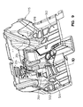
- FIG. 9 illustrates a perspective view of the floor body panel of FIGS. 6 and 7 ;
- FIG. 10 illustrates an enlarged perspective view of the floor body panel portion depicted in FIG. 9 ;
- FIG. 11 illustrates a cross-sectional view through the floor body panel as shown in Figure 10 .
- Vehicle 100 as illustrated includes a plurality of ground engaging members 102.
- ground engaging members 102 are wheels 104 and associated tires 106.
- Other exemplary ground engaging members include skis and tracks.
- one or more of the wheels may be replaced with tracks, such as the Prospector II Tracks available from Polaris Industries, Inc. located at 2100 Highway 55 in Medina, MN 55340.
- ground engaging members 102 are operatively coupled to a drive train 130 (see FIG. 2 ) to power the movement of vehicle 100.
- exemplary drive trains include prime movers such as combustion engines and electric engines, or a combination thereof, together with a transmission.
- a first set of wheels, one on each side of vehicle 100 generally correspond to a front axle 108.
- a second set of wheels, one on each side of vehicle 100 generally correspond to a rear axle 110.
- each of front axle 108 and rear axle 110 are shown having a single ground engaging member 102 on each side, multiple ground engaging members 102 may be included on each side of the respective front axle 108 and rear axle 110, or may include an optional third and rear axle.
- vehicle 100 is a four wheel, two axle vehicle having a frame 116 (see FIGS. 2 and 5 ) of vehicle 100.
- Frame 116 is supported by the ground engaging members 102 of vehicle 100.
- a drive train 130 is supported by frame 116 and may include a combustion engine.
- drive train 130 may include a multi-fuel engine capable of utilizing various fuels.
- drive train 130 includes a hybrid electric engine.
- drive train 130 includes an electric engine.
- vehicle 100 includes a bed 150 having a cargo carrying surface 152.
- Cargo carrying surface 152 may be flat, contoured, and/or comprised of several sections.
- bed 150 is rigidly coupled to frame 116.
- Bed portion 150 may include a tailgate 158 which may be lowered to improve ingress to and egress from bed 150.
- Bed 150 further includes a plurality of mounts 160 for receiving an expansion retainer (not shown) which may couple various accessories to bed 150. Additional details of such mounts and expansion retainers are provided in US Patent No. 7,055,454, to Whiting et al., filed July 13, 2004 , titled "Vehicle Expansion Retainers," the disclosure of which is expressly incorporated by reference herein.
- vehicle 100 includes an operator area 174 generally supported by frame 116.
- Operator area 174 includes seating 176 for one or more passengers.
- Operator area 174 further includes a plurality of operator controls 180 by which an operator may provide input into the control of vehicle 100.
- Controls 180 include a steering wheel 182 which is rotated by the operator to change the orientation of one or more of ground engaging members 102, such as the wheels associated with front axle 108, to steer vehicle 100.
- steering wheel 182 changes the orientation of the wheels of front axle 108 and rear axle 110 to provide four wheel steering.
- a vehicle operator position 192 on seating 176 is represented.
- a steering column 194 of steering wheel 182 is laterally centered as indicated by line 198 in the vehicle operator position 192.
- a gear shift input control 200 is operatively coupled to a shiftable transmission of drive train 130 to communicate whether the shiftable transmission is in a low forward gear, a high forward gear, a reverse gear, neutral, and if included, a park position.
- gear shift input control 200 is shown as a lever, other types of inputs may be used.
- Gear shift input control 200 is positioned on a right hand side of steering column 194.
- seating 176 includes a seat bottom portion 234 and a seat back portion 236.
- Seat bottom portion 234 is tilted from horizontal by about 8.5 degrees such that the back edge of the seat bottom (proximate the bed) is lower than the front edge of the seat bottom.
- Seat back portion 236 is titled towards bed 150 from vertical about 17 degrees.
- Seating 176 also includes head rests 238.
- seating 176 is a split bench with the operator side being adjustable along the longitudinal axis of vehicle 100.
- Drive train 130 (particularly the engine) may also be accessed by rotating seat bottom portion 234 forward.
- a latch lever 390 is provided that releases the back portion of seat bottom portion 234 allowing the back portion of seat bottom portion 234 to rotate forward.
- controls 180 also include a first foot pedal 204 actuatable by the vehicle operator to control the acceleration and speed of vehicle 100 through the control of drive train 130 and a second foot pedal 206 actuatable by the operator to decelerate vehicle 100 through a braking system.
- pedal 206 is offset to the right of steering column 194 such that both of the first foot pedal 204 and the second foot pedal 206 are generally in line with a right foot of an operator.
- seating 176 is shown in combination with a floor body panel 360, side body panels 362, and a removable under seat body panel 366.
- Seat body panel 366 is removable to allow access to drive train 130.
- Seat body panel 366 is further coupled to floor body panel 360 through connectors received in openings 374 in seat body panel 366 and through openings in the floor body panel 360.
- Seat body panel 366 is further coupled to side body panels 362 through fasteners 378 in seat body panel 366.
- Seat body panel 366 is removed to permit access to drive train 130 by removing the connectors attaching seat body panel 366 to floor body panel 360, first side body panel 362, and second side body panel 364 and then rotating and lifting seat body panel 366 relative to floor body panel 360 to uncouple retainers 370 from portions 372.
- a front body panel 398 is shown coupled to floor body panel 360, and an upper portion 404 of front body panel 398 overlaps dash body member 215. As such, dash body member 215, floor body panel 360, and front body panel 398 cooperate to close off operator area 174.
- floor body panel 360 is shown with the locations of pedal 204 and pedal 206.
- Floor body panel 360 further includes a guard member 394.
- Guard member 394 is positioned to prevent the foot of a passenger from entering vehicle operator position 192 and inadvertently depressing pedal 204.
- guard member 394 does not extend across to seat body panel 366, but is rather localized in the area corresponding to pedal 204.
- floor body panel 360 includes a driver floor body panel portion 500 having a recess or foot well 502.
- foot well 502 is comprised of a floor 504, rear wall 506, front wall 508, left side wall 510, and right side wall 512.
- Right side wall is comprised of straight section 512a and angled section 512b, as described herein.
- Floor 504 is further comprised of a groove 514 which is angled rearwardly from right to left (as viewed in FIG. 10 ), and which laterally overlaps at least a portion of both foot pedals 204 and 206 ( FIG. 9 ).
- a driver may place his or her heel in the foot well 502, either against the floor 504 or in the groove 514. In either event, this creates plural points of contact with the driver's foot, either along line 520 or line 522 ( Fig. 11 ), or along a multiple of other imaginary lines, depending on the particular resting position of the driver's heel.
- the driver can also rest his or her right hand side foot edge against angled section 512b, for guiding and aligning the foot with the accelerator foot pedal 204.
- the driver may place the end edge of the foot into the groove 514, and the groove can form a sliding guide when the foot is moved from the accelerator foot pedal 204 to the brake foot pedal 206. As the groove is angled rearwardly, the driver's foot is naturally moved rearwardly to accommodate the location of the brake foot pedal 206.
Landscapes
- Engineering & Computer Science (AREA)
- Chemical & Material Sciences (AREA)
- Combustion & Propulsion (AREA)
- Transportation (AREA)
- Mechanical Engineering (AREA)
- Body Structure For Vehicles (AREA)
- Auxiliary Drives, Propulsion Controls, And Safety Devices (AREA)
- Mechanical Control Devices (AREA)
- Passenger Equipment (AREA)
- Braking Elements And Transmission Devices (AREA)
- Automatic Cycles, And Cycles In General (AREA)
Claims (22)
- Fahrzeug (100), umfassend einen Fahrzeugrahmen (116), eine Antriebsmaschine (130), die am Rahmen befestigt ist, Räder (108, 110), die den Rahmen tragen, eine Bodenplatte (360) und eine Fußbedienung (204, 206) benachbart zur Bodenplatte, dadurch gekennzeichnet, dass die Bodenplatte eine Mehrzahl von Berührungsstellen (520, 522) zum Berühren eines Fußes eines Fahrers beim Betätigen der Fußbedienung aufweist, wobei die Mehrzahl von Berührungsstellen durch eine Aussparung (502) in der Bodenplatte definiert ist, und die Aussparung einen im Allgemeinen flachen Bodenabschnitt (504) und mindestens eine angrenzende Wand (506, 508, 510, 512) aufweist.
- Fahrzeug nach Anspruch 1, dadurch gekennzeichnet, dass die Aussparung im Allgemeinen rechteckig ist.
- Fahrzeug nach Anspruch 1 oder 2, dadurch gekennzeichnet, dass die Aussparung ferner eine sich seitlich erstreckende Nut (514) aufweist.
- Fahrzeug nach einem der Ansprüche 1 bis 3, ferner gekennzeichnet durch eine Mehrzahl von Fußbedienelementen (204, 206).
- Fahrzeug nach einem der Ansprüche 1 bis 4, dadurch gekennzeichnet, dass die Aussparung mindestens einen Teil der Mehrzahl von Fußbedienelementen seitlich überlappt.
- Fahrzeug nach Anspruch 4 oder 5, dadurch gekennzeichnet, dass die Mehrzahl von Fußbedienelementen ein Gaspedal (204) und ein Bremspedal (206) umfasst.
- Fahrzeug (100), umfassend einen Fahrzeugrahmen (116), eine Antriebsmaschine (130), die am Rahmen befestigt ist, Räder (108, 110), die den Rahmen tragen und durch die Antriebsmaschine angetrieben werden, eine Bodenplatte (360) und eine Fußbedienung (204, 206) benachbart zur Bodenplatte, dadurch gekennzeichnet, dass die Bodenplatte einen im Allgemeinen rechteckigen Fußraum (502) zur Aufnahme der Ferse eines Fußes eines Fahrers beim Betätigen der Fußbedienung aufweist.
- Fahrzeug nach Anspruch 7, dadurch gekennzeichnet, dass der Fußraum durch einen im Allgemeinen flachen Bodenabschnitt und mindestens eine Seitenkante (506, 508, 510, 512) definiert ist.
- Fahrzeug nach Anspruch 8, dadurch gekennzeichnet, dass die mindestens eine Seitenkante (508) profiliert ist, um die Sohle des Fußes des Fahrers zu berühren, wenn die Ferse des Fahrers im Fußraum ist.
- Fahrzeug nach einem der Ansprüche 7 bis 9, ferner gekennzeichnet durch eine Mehrzahl von Fußbedienelementen (204, 206).
- Fahrzeug nach Anspruch 10, dadurch gekennzeichnet, dass der Fußraum in der Bodenplatte mindestens einen Teil der Mehrzahl Fußbedienelementen seitlich überlappt.
- Fahrzeug nach Anspruch 10 oder 11, dadurch gekennzeichnet, dass die Mehrzahl von Fußbedienelementen ein Gaspedal (204) und ein Bremspedal (206) umfasst.
- Fahrzeug nach einem der Ansprüche 7 bis 12, dadurch gekennzeichnet, dass die Aussparung ferner eine sich seitlich erstreckende Nut (514) umfasst, die im flachen Bodenabschnitt ausgebildet ist, um die Stelle der Ferse des Fußes des Fahrers zu definieren, wenn in der Aussparung.
- Fahrzeug nach Anspruch 13, dadurch gekennzeichnet, dass sich die Nut nach hinten erstreckt, während sie von einer Position benachbart zu einer Längsmittellinie zu einer seitlich äußeren Position verläuft.
- Fahrzeug (100), umfassend einen Fahrzeugrahmen (116), eine Antriebsmaschine (130), die am Rahmen befestigt ist, Räder (108, 110), die den Rahmen tragen und durch die Antriebsmaschine angetrieben werden, eine Bodenplatte (360) und eine Mehrzahl von Fußbedienungen (204, 206) benachbart zur Bodenplatte, dadurch gekennzeichnet, dass die Bodenplatte eine Aussparung (502) zur Aufnahme der Ferse eines Fußes eines Fahrers beim Betätigen der Fußbedienung und eine sich seitlich erstreckende Nut (514) aufweist, die in der Aussparung ausgebildet ist und die Mehrzahl von Fußbedienungen seitlich flankiert, wobei die Nut profiliert ist, um eine Stelle für die Ferse eines Fußes eines Fahrers beim Betätigen der Mehrzahl von Fußbedienungen zu definieren.
- Fahrzeug nach Anspruch 15, dadurch gekennzeichnet, dass die Aussparung durch einen im Allgemeinen flachen Bodenabschnitt und mindestens eine Seitenkante (506, 508, 510, 512) definiert ist.
- Fahrzeug nach Anspruch 15 oder 16, dadurch gekennzeichnet, dass die Aussparung im Allgemeinen rechteckig ist.
- Fahrzeug nach einem der Ansprüche 15 bis 17, dadurch gekennzeichnet, dass die Aussparung im der Bodenplatte mindestens einen Teil der Mehrzahl von Fußbedienelementen seitlich überlappt.
- Fahrzeug nach Anspruch 15 bis 18, dadurch gekennzeichnet, dass die Mehrzahl von Fußbedienelementen ein Gaspedal (204) und ein Bremspedal (206) umfasst.
- Fahrzeug nach einem der Ansprüche 15 bis 19, dadurch gekennzeichnet, dass sich die Nut nach hinten erstreckt, während sie von einer Position benachbart zu einer Längsmittellinie zu einer seitlich äußeren Position verläuft.
- Fahrzeug nach einem der Ansprüche 15 bis 20, dadurch gekennzeichnet, dass die Aussparung eine Mehrzahl von Berührungsstellen (520, 522) zum Berühren eines Fußes eines Fahrers beim Betätigen der Fußbedingung definiert.
- Fahrzeug nach einem der Ansprüche 15 bis 21, dadurch gekennzeichnet, dass die Nut im flachen Bodenabschnitt der Aussparung definiert ist.
Applications Claiming Priority (2)
| Application Number | Priority Date | Filing Date | Title |
|---|---|---|---|
| US12/218,572 US8800706B2 (en) | 2008-07-16 | 2008-07-16 | Floorboard for a vehicle |
| PCT/US2009/049904 WO2010008979A1 (en) | 2008-07-16 | 2009-07-08 | Floorboard for a vehicle |
Publications (2)
| Publication Number | Publication Date |
|---|---|
| EP2307262A1 EP2307262A1 (de) | 2011-04-13 |
| EP2307262B1 true EP2307262B1 (de) | 2013-04-24 |
Family
ID=41169180
Family Applications (1)
| Application Number | Title | Priority Date | Filing Date |
|---|---|---|---|
| EP09790144.1A Not-in-force EP2307262B1 (de) | 2008-07-16 | 2009-07-08 | Bodenplatte für ein fahrzeug |
Country Status (9)
| Country | Link |
|---|---|
| US (1) | US8800706B2 (de) |
| EP (1) | EP2307262B1 (de) |
| CN (1) | CN102083679B (de) |
| AU (1) | AU2009271205B2 (de) |
| CA (1) | CA2728645C (de) |
| ES (1) | ES2407650T3 (de) |
| MX (1) | MX2011000223A (de) |
| WO (1) | WO2010008979A1 (de) |
| ZA (1) | ZA201100186B (de) |
Families Citing this family (33)
| Publication number | Priority date | Publication date | Assignee | Title |
|---|---|---|---|---|
| JP4951447B2 (ja) * | 2007-08-31 | 2012-06-13 | 本田技研工業株式会社 | 車両のフレーム構造 |
| US9393894B2 (en) | 2009-06-15 | 2016-07-19 | Polaris Industries Inc. | Side-by-side vehicle |
| US9162558B2 (en) | 2009-06-15 | 2015-10-20 | Polaris Industries Inc. | Electric vehicle |
| US8944449B2 (en) | 2010-04-06 | 2015-02-03 | Polaris Industries Inc. | Side-by-side vehicle |
| US10160497B2 (en) | 2011-02-01 | 2018-12-25 | Polaris Industries Inc. | All terrain vehicle |
| US9650078B2 (en) * | 2011-02-11 | 2017-05-16 | Polaris Industries Inc. | Side-by-side all terrain vehicle |
| US9180801B2 (en) | 2012-05-31 | 2015-11-10 | Arctic Cat Inc. | Vehicle configuration |
| US9327587B2 (en) | 2012-05-31 | 2016-05-03 | Arctic Cat Inc. | Off-highway recreational vehicle |
| US9592782B2 (en) | 2012-09-20 | 2017-03-14 | Polaris Industries Inc. | Vehicle |
| WO2014047488A1 (en) | 2012-09-20 | 2014-03-27 | Polaris Industries Inc. | Utiliy vehicle |
| US9440671B2 (en) | 2012-09-20 | 2016-09-13 | Polaris Industries Inc. | Vehicle |
| RU2015141215A (ru) * | 2013-03-01 | 2017-04-06 | Поларис Индастриз Инк. | Транспортное средство повышенной проходимости |
| CN111483524B (zh) | 2013-03-15 | 2023-05-23 | 北极星工业有限公司 | 多用途车辆 |
| CA3297418A1 (en) | 2013-05-31 | 2026-03-02 | Polaris Industries Inc. | Side-by-side utility vehicle |
| US9540052B2 (en) | 2013-08-14 | 2017-01-10 | Polaris Industries Inc. | Side-by-side vehicle |
| WO2015146901A1 (ja) * | 2014-03-28 | 2015-10-01 | 株式会社クボタ | 作業車 |
| CN118849684A (zh) | 2015-05-15 | 2024-10-29 | 北极星工业有限公司 | 多用途车辆 |
| JP6552406B2 (ja) * | 2015-12-24 | 2019-07-31 | 株式会社クボタ | 作業車 |
| EP3734401B1 (de) * | 2015-12-24 | 2022-03-23 | Kubota Corporation | Traktor und arbeitsfahrzeug |
| EP3468823B1 (de) | 2016-06-14 | 2024-09-04 | Polaris Industries Inc. | Hybridnutzfahrzeug |
| US11173808B2 (en) | 2016-12-22 | 2021-11-16 | Polaris Industies Inc. | Vehicle |
| USD835545S1 (en) | 2017-02-17 | 2018-12-11 | Polaris Industries Inc. | Off-road vehicle |
| US10793181B2 (en) | 2018-02-13 | 2020-10-06 | Polaris Industries Inc. | All-terrain vehicle |
| JP6823029B2 (ja) * | 2018-09-25 | 2021-01-27 | 本田技研工業株式会社 | フロア構造 |
| US10780770B2 (en) | 2018-10-05 | 2020-09-22 | Polaris Industries Inc. | Hybrid utility vehicle |
| CA3299418A1 (en) | 2019-04-30 | 2026-03-02 | Polaris Industries Inc. | Vehicle with removable final drive |
| US11370266B2 (en) | 2019-05-16 | 2022-06-28 | Polaris Industries Inc. | Hybrid utility vehicle |
| US11691674B2 (en) | 2020-05-15 | 2023-07-04 | Polaris Industries Inc. | Off-road vehicle |
| US12187127B2 (en) | 2020-05-15 | 2025-01-07 | Polaris Industries Inc. | Off-road vehicle |
| US12485981B2 (en) | 2021-03-24 | 2025-12-02 | Polaris Industries Inc. | Electric recreational vehicle |
| MX2023006716A (es) | 2022-06-13 | 2023-12-14 | Polaris Inc | Tren de potencia para vehiculo utilitario. |
| USD1067123S1 (en) | 2023-01-20 | 2025-03-18 | Polaris Industries Inc. | Off-road vehicle |
| USD1120805S1 (en) | 2023-06-29 | 2026-03-31 | Polaris Industries Inc. | Body assembly for an off-road vehicle |
Family Cites Families (28)
| Publication number | Priority date | Publication date | Assignee | Title |
|---|---|---|---|---|
| US1162959A (en) * | 1912-09-21 | 1915-12-07 | Brennan B West | Heel-rest. |
| US2062114A (en) * | 1929-09-16 | 1936-11-24 | Samuel F Bashara | Heel cushion |
| US2136980A (en) * | 1937-03-08 | 1938-11-15 | Pim Joane | Heel support |
| US2761329A (en) * | 1954-10-22 | 1956-09-04 | Eugene B Reed | Resiliently supported heel rest |
| US3047088A (en) * | 1961-01-13 | 1962-07-31 | Carl T Murrell | Foot rest for vehicle drivers |
| US3275094A (en) * | 1964-07-22 | 1966-09-27 | Ford Motor Co | Motor vehicle pedal support |
| US3424265A (en) * | 1967-04-21 | 1969-01-28 | Stanley S Stata | Removable and replaceable combination pan and floor grate for motor vehicles |
| US3426615A (en) * | 1967-05-29 | 1969-02-11 | Raymond C Strauss | Vehicle driving controls |
| DE3531805A1 (de) * | 1985-09-06 | 1987-03-19 | Daimler Benz Ag | Energieabsorbierend ausgebildeter fussabstuetzkoerper |
| IT8903569A0 (it) | 1989-07-28 | 1989-07-28 | O M S I S A S Di Baccaro Vince | Pedana appoggia piedi per autoveicoli |
| US5201245A (en) * | 1989-09-29 | 1993-04-13 | Masuyuki Naruse | Drive control system for an automobile |
| JPH0725293B2 (ja) | 1989-09-29 | 1995-03-22 | 益幸 鳴瀬 | 自動車運転操作システム |
| US4991900A (en) * | 1989-10-10 | 1991-02-12 | White A Leon | Floor covering |
| JPH04129885A (ja) | 1990-09-20 | 1992-04-30 | Masuyuki Naruse | 車両運転席の床構造 |
| JP2957133B2 (ja) * | 1996-09-09 | 1999-10-04 | 川崎重工業株式会社 | 騎乗型自動4輪車 |
| JP3908824B2 (ja) * | 1997-05-28 | 2007-04-25 | 本田技研工業株式会社 | 自動車の車体構造 |
| GB2341151A (en) * | 1998-08-29 | 2000-03-08 | Rover Group | A motor vehicle foot pedal |
| US6131485A (en) * | 1998-10-29 | 2000-10-17 | Raja; Shaffaqat H. | Foot pedal extension system |
| JP3828826B2 (ja) * | 2002-04-17 | 2006-10-04 | 本田技研工業株式会社 | 自動車におけるヒールストッパの衝撃吸収構造 |
| US7367417B2 (en) * | 2003-04-02 | 2008-05-06 | Yamaha Hatsudoki Kabushiki Kaisha | Floor arrangement for off-road vehicle |
| JP4233954B2 (ja) * | 2003-08-07 | 2009-03-04 | ポップリベット・ファスナー株式会社 | 乗員保護部材をボデーパネルに取付ける装置 |
| US7422082B2 (en) * | 2005-04-29 | 2008-09-09 | Yamaha Motor Mfg. Corp. Of America | Small-sized vehicle |
| EP1816056B1 (de) | 2006-02-02 | 2016-11-02 | Mazda Motor Corporation | Vorrichtung für einen beweglichen Boden eines Kraftfahrzeugs |
| JP2007216751A (ja) * | 2006-02-15 | 2007-08-30 | Mazda Motor Corp | 運転姿勢調節装置 |
| US7656385B2 (en) * | 2006-04-28 | 2010-02-02 | Microsoft Corporation | Slip resistant and/or non-linear force response pedal peripheral device |
| US7695056B2 (en) * | 2006-05-05 | 2010-04-13 | Textron Innovations Inc. | Floorboard for light-weight vehicle |
| JP4951447B2 (ja) * | 2007-08-31 | 2012-06-13 | 本田技研工業株式会社 | 車両のフレーム構造 |
| US7946641B2 (en) * | 2008-03-04 | 2011-05-24 | Mazda Motor Corporation | Driver-side floor structure of vehicle |
-
2008
- 2008-07-16 US US12/218,572 patent/US8800706B2/en active Active
-
2009
- 2009-07-08 EP EP09790144.1A patent/EP2307262B1/de not_active Not-in-force
- 2009-07-08 MX MX2011000223A patent/MX2011000223A/es active IP Right Grant
- 2009-07-08 AU AU2009271205A patent/AU2009271205B2/en not_active Ceased
- 2009-07-08 WO PCT/US2009/049904 patent/WO2010008979A1/en not_active Ceased
- 2009-07-08 ES ES09790144T patent/ES2407650T3/es active Active
- 2009-07-08 CA CA2728645A patent/CA2728645C/en active Active
- 2009-07-08 CN CN200980126336.XA patent/CN102083679B/zh active Active
-
2011
- 2011-01-06 ZA ZA2011/00186A patent/ZA201100186B/en unknown
Also Published As
| Publication number | Publication date |
|---|---|
| MX2011000223A (es) | 2011-02-22 |
| WO2010008979A1 (en) | 2010-01-21 |
| CA2728645A1 (en) | 2010-01-21 |
| EP2307262A1 (de) | 2011-04-13 |
| CA2728645C (en) | 2016-10-11 |
| CN102083679A (zh) | 2011-06-01 |
| ES2407650T3 (es) | 2013-06-13 |
| US20100012412A1 (en) | 2010-01-21 |
| CN102083679B (zh) | 2015-07-15 |
| AU2009271205A1 (en) | 2010-01-21 |
| WO2010008979A9 (en) | 2010-06-24 |
| AU2009271205B2 (en) | 2014-07-17 |
| ZA201100186B (en) | 2011-10-26 |
| HK1157294A1 (en) | 2012-06-29 |
| US8800706B2 (en) | 2014-08-12 |
Similar Documents
| Publication | Publication Date | Title |
|---|---|---|
| CA2728645C (en) | Floorboard for a vehicle | |
| CA2746655C (en) | Vehicle | |
| US10011189B2 (en) | Side-by-side ATV | |
| US8382125B2 (en) | Side-by-side ATV | |
| US9764767B2 (en) | Off-road wheeled side-by-side vehicle having a storage space | |
| US9932073B2 (en) | Off-road wheeled side-by-side vehicle | |
| US20170225565A1 (en) | Vehicle | |
| US20170174027A1 (en) | Off-road wheeled side-by-side vehicle | |
| US20030102694A1 (en) | ATV with improved driver positioning and/or multi passenger capacity | |
| GB2531076A (en) | Amphibian | |
| HK1157294B (en) | Vehicle | |
| JP2025141297A (ja) | 作業車 | |
| HK1163611B (zh) | 车辆 |
Legal Events
| Date | Code | Title | Description |
|---|---|---|---|
| PUAI | Public reference made under article 153(3) epc to a published international application that has entered the european phase |
Free format text: ORIGINAL CODE: 0009012 |
|
| 17P | Request for examination filed |
Effective date: 20110203 |
|
| AK | Designated contracting states |
Kind code of ref document: A1 Designated state(s): AT BE BG CH CY CZ DE DK EE ES FI FR GB GR HR HU IE IS IT LI LT LU LV MC MK MT NL NO PL PT RO SE SI SK SM TR |
|
| AX | Request for extension of the european patent |
Extension state: AL BA RS |
|
| DAX | Request for extension of the european patent (deleted) | ||
| RIN1 | Information on inventor provided before grant (corrected) |
Inventor name: GARDNER, JEFFREY, LYNN Inventor name: DECKARD, AARON, DAVID |
|
| GRAP | Despatch of communication of intention to grant a patent |
Free format text: ORIGINAL CODE: EPIDOSNIGR1 |
|
| GRAS | Grant fee paid |
Free format text: ORIGINAL CODE: EPIDOSNIGR3 |
|
| GRAA | (expected) grant |
Free format text: ORIGINAL CODE: 0009210 |
|
| AK | Designated contracting states |
Kind code of ref document: B1 Designated state(s): AT BE BG CH CY CZ DE DK EE ES FI FR GB GR HR HU IE IS IT LI LT LU LV MC MK MT NL NO PL PT RO SE SI SK SM TR |
|
| REG | Reference to a national code |
Ref country code: GB Ref legal event code: FG4D |
|
| REG | Reference to a national code |
Ref country code: CH Ref legal event code: EP |
|
| REG | Reference to a national code |
Ref country code: AT Ref legal event code: REF Ref document number: 608448 Country of ref document: AT Kind code of ref document: T Effective date: 20130515 |
|
| REG | Reference to a national code |
Ref country code: IE Ref legal event code: FG4D |
|
| REG | Reference to a national code |
Ref country code: ES Ref legal event code: FG2A Ref document number: 2407650 Country of ref document: ES Kind code of ref document: T3 Effective date: 20130613 |
|
| REG | Reference to a national code |
Ref country code: DE Ref legal event code: R096 Ref document number: 602009015295 Country of ref document: DE Effective date: 20130620 |
|
| REG | Reference to a national code |
Ref country code: SE Ref legal event code: TRGR |
|
| REG | Reference to a national code |
Ref country code: NO Ref legal event code: T2 Effective date: 20130424 |
|
| REG | Reference to a national code |
Ref country code: AT Ref legal event code: MK05 Ref document number: 608448 Country of ref document: AT Kind code of ref document: T Effective date: 20130424 |
|
| REG | Reference to a national code |
Ref country code: LT Ref legal event code: MG4D |
|
| REG | Reference to a national code |
Ref country code: NL Ref legal event code: VDEP Effective date: 20130424 |
|
| PG25 | Lapsed in a contracting state [announced via postgrant information from national office to epo] |
Ref country code: AT Free format text: LAPSE BECAUSE OF FAILURE TO SUBMIT A TRANSLATION OF THE DESCRIPTION OR TO PAY THE FEE WITHIN THE PRESCRIBED TIME-LIMIT Effective date: 20130424 Ref country code: PT Free format text: LAPSE BECAUSE OF FAILURE TO SUBMIT A TRANSLATION OF THE DESCRIPTION OR TO PAY THE FEE WITHIN THE PRESCRIBED TIME-LIMIT Effective date: 20130826 Ref country code: LT Free format text: LAPSE BECAUSE OF FAILURE TO SUBMIT A TRANSLATION OF THE DESCRIPTION OR TO PAY THE FEE WITHIN THE PRESCRIBED TIME-LIMIT Effective date: 20130424 Ref country code: SI Free format text: LAPSE BECAUSE OF FAILURE TO SUBMIT A TRANSLATION OF THE DESCRIPTION OR TO PAY THE FEE WITHIN THE PRESCRIBED TIME-LIMIT Effective date: 20130424 Ref country code: GR Free format text: LAPSE BECAUSE OF FAILURE TO SUBMIT A TRANSLATION OF THE DESCRIPTION OR TO PAY THE FEE WITHIN THE PRESCRIBED TIME-LIMIT Effective date: 20130725 Ref country code: BE Free format text: LAPSE BECAUSE OF FAILURE TO SUBMIT A TRANSLATION OF THE DESCRIPTION OR TO PAY THE FEE WITHIN THE PRESCRIBED TIME-LIMIT Effective date: 20130424 Ref country code: IS Free format text: LAPSE BECAUSE OF FAILURE TO SUBMIT A TRANSLATION OF THE DESCRIPTION OR TO PAY THE FEE WITHIN THE PRESCRIBED TIME-LIMIT Effective date: 20130824 |
|
| PG25 | Lapsed in a contracting state [announced via postgrant information from national office to epo] |
Ref country code: HR Free format text: LAPSE BECAUSE OF FAILURE TO SUBMIT A TRANSLATION OF THE DESCRIPTION OR TO PAY THE FEE WITHIN THE PRESCRIBED TIME-LIMIT Effective date: 20130424 Ref country code: CY Free format text: LAPSE BECAUSE OF FAILURE TO SUBMIT A TRANSLATION OF THE DESCRIPTION OR TO PAY THE FEE WITHIN THE PRESCRIBED TIME-LIMIT Effective date: 20130424 Ref country code: BG Free format text: LAPSE BECAUSE OF FAILURE TO SUBMIT A TRANSLATION OF THE DESCRIPTION OR TO PAY THE FEE WITHIN THE PRESCRIBED TIME-LIMIT Effective date: 20130724 Ref country code: PL Free format text: LAPSE BECAUSE OF FAILURE TO SUBMIT A TRANSLATION OF THE DESCRIPTION OR TO PAY THE FEE WITHIN THE PRESCRIBED TIME-LIMIT Effective date: 20130424 Ref country code: LV Free format text: LAPSE BECAUSE OF FAILURE TO SUBMIT A TRANSLATION OF THE DESCRIPTION OR TO PAY THE FEE WITHIN THE PRESCRIBED TIME-LIMIT Effective date: 20130424 |
|
| PG25 | Lapsed in a contracting state [announced via postgrant information from national office to epo] |
Ref country code: SK Free format text: LAPSE BECAUSE OF FAILURE TO SUBMIT A TRANSLATION OF THE DESCRIPTION OR TO PAY THE FEE WITHIN THE PRESCRIBED TIME-LIMIT Effective date: 20130424 Ref country code: EE Free format text: LAPSE BECAUSE OF FAILURE TO SUBMIT A TRANSLATION OF THE DESCRIPTION OR TO PAY THE FEE WITHIN THE PRESCRIBED TIME-LIMIT Effective date: 20130424 Ref country code: DK Free format text: LAPSE BECAUSE OF FAILURE TO SUBMIT A TRANSLATION OF THE DESCRIPTION OR TO PAY THE FEE WITHIN THE PRESCRIBED TIME-LIMIT Effective date: 20130424 Ref country code: CZ Free format text: LAPSE BECAUSE OF FAILURE TO SUBMIT A TRANSLATION OF THE DESCRIPTION OR TO PAY THE FEE WITHIN THE PRESCRIBED TIME-LIMIT Effective date: 20130424 |
|
| PG25 | Lapsed in a contracting state [announced via postgrant information from national office to epo] |
Ref country code: MC Free format text: LAPSE BECAUSE OF FAILURE TO SUBMIT A TRANSLATION OF THE DESCRIPTION OR TO PAY THE FEE WITHIN THE PRESCRIBED TIME-LIMIT Effective date: 20130424 Ref country code: NL Free format text: LAPSE BECAUSE OF FAILURE TO SUBMIT A TRANSLATION OF THE DESCRIPTION OR TO PAY THE FEE WITHIN THE PRESCRIBED TIME-LIMIT Effective date: 20130424 Ref country code: RO Free format text: LAPSE BECAUSE OF FAILURE TO SUBMIT A TRANSLATION OF THE DESCRIPTION OR TO PAY THE FEE WITHIN THE PRESCRIBED TIME-LIMIT Effective date: 20130424 |
|
| PLBE | No opposition filed within time limit |
Free format text: ORIGINAL CODE: 0009261 |
|
| REG | Reference to a national code |
Ref country code: CH Ref legal event code: PL |
|
| STAA | Information on the status of an ep patent application or granted ep patent |
Free format text: STATUS: NO OPPOSITION FILED WITHIN TIME LIMIT |
|
| 26N | No opposition filed |
Effective date: 20140127 |
|
| REG | Reference to a national code |
Ref country code: IE Ref legal event code: MM4A |
|
| PG25 | Lapsed in a contracting state [announced via postgrant information from national office to epo] |
Ref country code: LI Free format text: LAPSE BECAUSE OF NON-PAYMENT OF DUE FEES Effective date: 20130731 Ref country code: CH Free format text: LAPSE BECAUSE OF NON-PAYMENT OF DUE FEES Effective date: 20130731 |
|
| REG | Reference to a national code |
Ref country code: DE Ref legal event code: R097 Ref document number: 602009015295 Country of ref document: DE Effective date: 20140127 |
|
| PG25 | Lapsed in a contracting state [announced via postgrant information from national office to epo] |
Ref country code: IE Free format text: LAPSE BECAUSE OF NON-PAYMENT OF DUE FEES Effective date: 20130708 |
|
| PG25 | Lapsed in a contracting state [announced via postgrant information from national office to epo] |
Ref country code: SM Free format text: LAPSE BECAUSE OF FAILURE TO SUBMIT A TRANSLATION OF THE DESCRIPTION OR TO PAY THE FEE WITHIN THE PRESCRIBED TIME-LIMIT Effective date: 20130424 |
|
| PG25 | Lapsed in a contracting state [announced via postgrant information from national office to epo] |
Ref country code: TR Free format text: LAPSE BECAUSE OF FAILURE TO SUBMIT A TRANSLATION OF THE DESCRIPTION OR TO PAY THE FEE WITHIN THE PRESCRIBED TIME-LIMIT Effective date: 20130424 Ref country code: MT Free format text: LAPSE BECAUSE OF FAILURE TO SUBMIT A TRANSLATION OF THE DESCRIPTION OR TO PAY THE FEE WITHIN THE PRESCRIBED TIME-LIMIT Effective date: 20130424 |
|
| PG25 | Lapsed in a contracting state [announced via postgrant information from national office to epo] |
Ref country code: HU Free format text: LAPSE BECAUSE OF FAILURE TO SUBMIT A TRANSLATION OF THE DESCRIPTION OR TO PAY THE FEE WITHIN THE PRESCRIBED TIME-LIMIT; INVALID AB INITIO Effective date: 20090708 Ref country code: MK Free format text: LAPSE BECAUSE OF FAILURE TO SUBMIT A TRANSLATION OF THE DESCRIPTION OR TO PAY THE FEE WITHIN THE PRESCRIBED TIME-LIMIT Effective date: 20130424 Ref country code: LU Free format text: LAPSE BECAUSE OF NON-PAYMENT OF DUE FEES Effective date: 20130708 |
|
| PGFP | Annual fee paid to national office [announced via postgrant information from national office to epo] |
Ref country code: NO Payment date: 20150714 Year of fee payment: 7 |
|
| REG | Reference to a national code |
Ref country code: FR Ref legal event code: PLFP Year of fee payment: 8 |
|
| REG | Reference to a national code |
Ref country code: NO Ref legal event code: MMEP |
|
| PG25 | Lapsed in a contracting state [announced via postgrant information from national office to epo] |
Ref country code: NO Free format text: LAPSE BECAUSE OF NON-PAYMENT OF DUE FEES Effective date: 20160731 |
|
| REG | Reference to a national code |
Ref country code: FR Ref legal event code: PLFP Year of fee payment: 9 |
|
| REG | Reference to a national code |
Ref country code: FR Ref legal event code: PLFP Year of fee payment: 10 |
|
| PGFP | Annual fee paid to national office [announced via postgrant information from national office to epo] |
Ref country code: IT Payment date: 20180724 Year of fee payment: 10 Ref country code: FR Payment date: 20180725 Year of fee payment: 10 Ref country code: ES Payment date: 20180829 Year of fee payment: 10 Ref country code: DE Payment date: 20180723 Year of fee payment: 10 |
|
| PGFP | Annual fee paid to national office [announced via postgrant information from national office to epo] |
Ref country code: SE Payment date: 20180719 Year of fee payment: 10 Ref country code: GB Payment date: 20180719 Year of fee payment: 10 Ref country code: FI Payment date: 20180720 Year of fee payment: 10 |
|
| REG | Reference to a national code |
Ref country code: DE Ref legal event code: R119 Ref document number: 602009015295 Country of ref document: DE |
|
| REG | Reference to a national code |
Ref country code: FI Ref legal event code: MAE |
|
| REG | Reference to a national code |
Ref country code: SE Ref legal event code: EUG |
|
| GBPC | Gb: european patent ceased through non-payment of renewal fee |
Effective date: 20190708 |
|
| PG25 | Lapsed in a contracting state [announced via postgrant information from national office to epo] |
Ref country code: DE Free format text: LAPSE BECAUSE OF NON-PAYMENT OF DUE FEES Effective date: 20200201 Ref country code: SE Free format text: LAPSE BECAUSE OF NON-PAYMENT OF DUE FEES Effective date: 20190709 Ref country code: GB Free format text: LAPSE BECAUSE OF NON-PAYMENT OF DUE FEES Effective date: 20190708 Ref country code: FI Free format text: LAPSE BECAUSE OF NON-PAYMENT OF DUE FEES Effective date: 20190708 |
|
| PG25 | Lapsed in a contracting state [announced via postgrant information from national office to epo] |
Ref country code: FR Free format text: LAPSE BECAUSE OF NON-PAYMENT OF DUE FEES Effective date: 20190731 |
|
| PG25 | Lapsed in a contracting state [announced via postgrant information from national office to epo] |
Ref country code: IT Free format text: LAPSE BECAUSE OF NON-PAYMENT OF DUE FEES Effective date: 20190708 |
|
| REG | Reference to a national code |
Ref country code: ES Ref legal event code: FD2A Effective date: 20201126 |
|
| PG25 | Lapsed in a contracting state [announced via postgrant information from national office to epo] |
Ref country code: ES Free format text: LAPSE BECAUSE OF NON-PAYMENT OF DUE FEES Effective date: 20190709 |