EP2306136A2 - Rohr-Rippen-Wärmeübertrager mit Seitenteilen - Google Patents
Rohr-Rippen-Wärmeübertrager mit Seitenteilen Download PDFInfo
- Publication number
- EP2306136A2 EP2306136A2 EP10175312A EP10175312A EP2306136A2 EP 2306136 A2 EP2306136 A2 EP 2306136A2 EP 10175312 A EP10175312 A EP 10175312A EP 10175312 A EP10175312 A EP 10175312A EP 2306136 A2 EP2306136 A2 EP 2306136A2
- Authority
- EP
- European Patent Office
- Prior art keywords
- heat exchanger
- side part
- tube
- block
- elements
- Prior art date
- Legal status (The legal status is an assumption and is not a legal conclusion. Google has not performed a legal analysis and makes no representation as to the accuracy of the status listed.)
- Granted
Links
Images

Classifications
-
- F—MECHANICAL ENGINEERING; LIGHTING; HEATING; WEAPONS; BLASTING
- F28—HEAT EXCHANGE IN GENERAL
- F28D—HEAT-EXCHANGE APPARATUS, NOT PROVIDED FOR IN ANOTHER SUBCLASS, IN WHICH THE HEAT-EXCHANGE MEDIA DO NOT COME INTO DIRECT CONTACT
- F28D1/00—Heat-exchange apparatus having stationary conduit assemblies for one heat-exchange medium only, the media being in contact with different sides of the conduit wall, in which the other heat-exchange medium is a large body of fluid, e.g. domestic or motor car radiators
- F28D1/02—Heat-exchange apparatus having stationary conduit assemblies for one heat-exchange medium only, the media being in contact with different sides of the conduit wall, in which the other heat-exchange medium is a large body of fluid, e.g. domestic or motor car radiators with heat-exchange conduits immersed in the body of fluid
- F28D1/04—Heat-exchange apparatus having stationary conduit assemblies for one heat-exchange medium only, the media being in contact with different sides of the conduit wall, in which the other heat-exchange medium is a large body of fluid, e.g. domestic or motor car radiators with heat-exchange conduits immersed in the body of fluid with tubular conduits
- F28D1/053—Heat-exchange apparatus having stationary conduit assemblies for one heat-exchange medium only, the media being in contact with different sides of the conduit wall, in which the other heat-exchange medium is a large body of fluid, e.g. domestic or motor car radiators with heat-exchange conduits immersed in the body of fluid with tubular conduits the conduits being straight
- F28D1/0535—Heat-exchange apparatus having stationary conduit assemblies for one heat-exchange medium only, the media being in contact with different sides of the conduit wall, in which the other heat-exchange medium is a large body of fluid, e.g. domestic or motor car radiators with heat-exchange conduits immersed in the body of fluid with tubular conduits the conduits being straight the conduits having a non-circular cross-section
- F28D1/05366—Assemblies of conduits connected to common headers, e.g. core type radiators
-
- F—MECHANICAL ENGINEERING; LIGHTING; HEATING; WEAPONS; BLASTING
- F28—HEAT EXCHANGE IN GENERAL
- F28F—DETAILS OF HEAT-EXCHANGE AND HEAT-TRANSFER APPARATUS, OF GENERAL APPLICATION
- F28F9/00—Casings; Header boxes; Auxiliary supports for elements; Auxiliary members within casings
- F28F9/001—Casings in the form of plate-like arrangements; Frames enclosing a heat exchange core
-
- F—MECHANICAL ENGINEERING; LIGHTING; HEATING; WEAPONS; BLASTING
- F28—HEAT EXCHANGE IN GENERAL
- F28F—DETAILS OF HEAT-EXCHANGE AND HEAT-TRANSFER APPARATUS, OF GENERAL APPLICATION
- F28F9/00—Casings; Header boxes; Auxiliary supports for elements; Auxiliary members within casings
- F28F9/02—Header boxes; End plates
- F28F9/0219—Arrangements for sealing end plates into casing or header box; Header box sub-elements
- F28F9/0224—Header boxes formed by sealing end plates into covers
-
- F—MECHANICAL ENGINEERING; LIGHTING; HEATING; WEAPONS; BLASTING
- F28—HEAT EXCHANGE IN GENERAL
- F28F—DETAILS OF HEAT-EXCHANGE AND HEAT-TRANSFER APPARATUS, OF GENERAL APPLICATION
- F28F2275/00—Fastening; Joining
- F28F2275/12—Fastening; Joining by methods involving deformation of the elements
-
- F—MECHANICAL ENGINEERING; LIGHTING; HEATING; WEAPONS; BLASTING
- F28—HEAT EXCHANGE IN GENERAL
- F28F—DETAILS OF HEAT-EXCHANGE AND HEAT-TRANSFER APPARATUS, OF GENERAL APPLICATION
- F28F2275/00—Fastening; Joining
- F28F2275/12—Fastening; Joining by methods involving deformation of the elements
- F28F2275/122—Fastening; Joining by methods involving deformation of the elements by crimping, caulking or clinching
Definitions
- the invention relates to a heat exchanger according to the preamble of claim 1.
- Heat exchangers in particular heat exchangers such as gas coolers or condensers, which are used in the automotive sector, are essentially constructed of corrugated flat-tube blocks which terminate at respective opposite end portions in headers.
- heat exchangers are manufactured by means of a cassetting process.
- the corrugated finned flat tube block is stretched and pressed onto the manifolds.
- vibrations, thermal expansions or residual stresses of the collecting tube in the brazing furnace can lead to a relative movement of the collecting tube relative to the flat tubes.
- a heat exchanger for a motor vehicle which has a corrugated flat-tube block which is bounded on opposite sides by two side parts, which are also designed as flat tube profiles which are identical to the flat tube profiles of the corrugated flat-tube block, but not of one Heat transfer medium to be flowed through.
- the heat exchanger is designed in all-metal construction, in which both the corrugated flat-tube block and provided on both end faces of the block tube plates are each made of light metal alloys.
- Each tubesheet is provided on its opposite sides in the region of its directed away from the corrugated flat-tube block edge with two spaced, integrally formed bending tabs which are umbiegbar to secure the flat tube profiles on corrugated flat-tube block before soldering to the outside.
- the bending tabs serving as mechanically acting fastening elements overlap the side parts in a form-fitting manner, as a result of which the side parts are position-secured on the corrugated ribbed flat-tube block and on the tubesheets.
- the additional provision of a clamping frame for transport or storage of the corrugated flat-tube block including the side parts before soldering can thus be avoided.
- a heat exchanger in particular a gas cooler for a motor vehicle, which has a block of tubular elements and rib elements, wherein the block is provided on at least one side surface with a side part, and pressed on at least one top and / or one bottom on a manifold is, which is respectively formed with a plurality of recesses for receiving the tubular elements.
- the provided at least on one side surface of the block side part is caulked according to the invention with the at least one of the top or the bottom pressed-together manifold.
- the tube elements are designed as flat tubes and the rib elements as corrugated ribs.
- the tubular elements can be flowed through by a heating or cooling medium.
- the side part is a pipe element which can not be flowed through by a heat or cooling medium, in particular a flat pipe. This is particularly cost effective, since no additional parts must be made.
- the side part has at least one punctiform deformation, in particular a multiplicity of punctiform deformations.
- the punctual deformations can be executed in any shape and number.
- the side part is formed as a metal strip
- the sheet metal strip may preferably be formed to I, U or L profile.
- the side member is pushed through an outer recess of the plurality of recesses, so that an end portion of the side member is disposed in the header pipe.
- the side part has at least a punctual deformation at the arranged in the collecting tube end portion, by the punctual deformation of the in the Collecting tube arranged end portion prevents the pipe elements from falling out of the manifold, for example during transport,
- the side part has at least one further punctiform deformation on an outer section arranged outside the collecting tube. This advantageously prevents the tube elements from being pushed too deeply into the collecting tube.
- the tubular elements are produced by means of an extrusion process.
- the heat exchanger is manufactured by means of a Kassettier Kunststoffes.
- each of the plurality of recesses is formed as a passage for a respective pipe member.
- the collecting tube has two outer passages formed as passages for receiving in each case a side part, which may be formed as open passages.
- the heat exchanger can be designed as a gas cooler or as a capacitor.
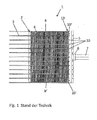
- Fig. 1 is a schematic view of a portion of a heat exchanger 1 according to the prior art.
- the heat exchanger 1 has a block 2, which consists of tubular elements 3 and rib elements 4, which are formed as flat tubes and corrugated ribs, which are arranged alternately.
- the rib elements 4 of the block 2 are not completely shown in the figure and cover here only a part of the block 2 from.
- the underside or, left side of the heat exchanger 1 is not shown in the figure; However, this is essentially like the top or right side of the heat exchanger 1 constructed.
- the block 2 has an upper side 13 and a lower side (not shown).
- the block 2 On its upper side 13 and, its underside, the block 2 is pressed onto a respective collecting tube 8, 8 ', wherein the tube ends of the individual tube elements 3 are pressed on opposite end faces into respective recesses 10, 10' of a collecting tube 5, which are designed as passages, and in the figure, as already mentioned above, only the right manifold 5 is shown
- the upper or right manifold 5 has a Anslhlussstutzen 6 for a supply and return 7 of a cooling or dressing Jerusalemriuss (not shown).
- the opposite narrow sides of the block 2 are each provided with a side part 8, 8 ', each at an upper end portion and a lower end portion (not shown) in an outer formed as a passage recess 10' of the plurality of as passages formed before soldering the parts of the heat roller bearing 1, the individual tube elements 3 in the embodiment of the prior art shown here only by the static friction of the tubular elements 3 and the side parts 8, 8 'in as Passages formed recesses 10, 10 'of the manifold 5, which can lead to problems during transport to the soldering furnaces, when the position of the tubular elements 3 changes with respect to the manifold 5 or even completely slip out of the manifold 5.
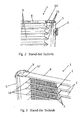
- Fig. 2 shows a perspective view of an upper or right portion of a heat exchanger 1 according to the prior art, which is shown here without rib elements 4 and only with tubular elements 3.
- the collecting tube 5 has a plurality of passages 10 formed as passages and on both sides each formed as an outer passage recess 10 ', of which only one is shown here. All formed as passages recesses 10, 10 'are of identical design and arranged at a uniform distance from each other on the manifold 5.
- the side part 8 is inserted in the same manner as the pipe element 3 or, pressed, with as side part 8 here is a correspondingly shaped sheet metal strip.
- the collecting tube 5 is - as already described above - before soldering - only held by the static friction of the individual tube elements 3 and the side parts 8, 8 'on this and can therefore easily solve or slip.
- Fig. 3 is another perspective view of a portion of a heat exchanger 1 according to the prior art with a block 2 of alternately arranged tubular elements 3 and fin elements 4, wherein the tube elements 3 at their end portions (not shown) in the manifold 5 by respective recesses formed as passages 10th introduced are.
- a side part 8 in this embodiment a non-flowed through by a heat or coolant tube element has been used, which is used with its end portion 9 in a formed as an outer passage recess 10 'of the plurality of passages formed as passages 10 of the manifold 5.
- the outer recess formed as a passage 10 ' is made open, and thus differs from the formed as passages recesses 10 of the manifold fifth
- Fig. 4 is a perspective view of a portion of a heat exchanger 1 according to an embodiment.
- the side part 8 is formed as a non-flowed through by a heat or cooling medium tube member 3 and forms a lateral termination of the block 2.
- a heat or coolant tube member 3 instead of a non-flowed through by a heat or coolant tube member 3 but also a corresponding shaped sheet metal strip or a profile element can be used.
- the block 2 is (not shown) on its upper side 13 and / or pressed onto the manifold 5 by the tube elements 3 (not shown) at their end portions in respective passages 10 which are provided in the manifold 5, are pressed.
- an end portion 9 of the side part 8 is pressed, wherein the end portion 9 protrudes over a certain length in the manifold 5
- the side part 8 at this end portion. 9 two punctual deformations 11, 11 '.
- the opposite end portion of the side part 8, which is not shown here, is constructed or formed substantially the same.
- the two punctual deformations 11, 11 ' which in the interior of the manifold 5 on opposite sides the edge portions 12, 12 'of the side part 8' are provided, prevent the collecting tube 5 from slipping off the side part 8, 8 '.
- the two punctiform deformations 11, 11 ' are substantially round in this embodiment, but may be formed in any other shape, such as four-, six- or octagonal.
- Two further punctual deformations 11 ', 11'", which are here quadrangular, are on opposite sides of the edge portions 12, 12 'before the outer passage 10', through which the side part 8 is pushed - ie outside of the manifold 5 - to an outer portion 14 of the side part 8 is provided, so that the side part 8 is not inserted too deeply into the collecting tube 5.
- the side part 8 with the manifold 5 by the punctual deformations 11, 11 ', 11 ", 11'” caulked and can not be displaced in position before soldering or slip out of the manifold 5.
- the outer passages 10 ' may alternatively as open or closed passages or recesses 10', as in connection with FIG. 3 has been described, executed or have a different tolerance position.
Landscapes
- Engineering & Computer Science (AREA)
- Physics & Mathematics (AREA)
- Thermal Sciences (AREA)
- Mechanical Engineering (AREA)
- General Engineering & Computer Science (AREA)
- Heat-Exchange Devices With Radiators And Conduit Assemblies (AREA)
- Details Of Heat-Exchange And Heat-Transfer (AREA)
Abstract
Description
- Die Erfindung betrifft einen Wärmeübertrager gemäß dem Oberbegriff des Anspruchs 1.
- Wärmeübertager, insbesondere Wärmeübertrager wie Gaskühler oder Kondensatoren, welche im Kraftfahrzeugbereich eingesetzt werden, sind im Wesentlichen aus Wellrippen-Flachrohr-Blöcken aufgebaut, die an jeweiligen gegenüberliegenden Endabschnitten in Sammelrohren enden. Üblicherweise werden im Stand der Technik Wärmeübertrager mittels eines Kassettierverfahrens hergestellt. Bei der Kassettierung von Wärrneübertragern, insbesondere bei der Kassettierung von Gaskühler, wird der Wellrippen-Flachrohr-Block gespannt und auf die Sammelrohre aufgepresst. Während des dann diesem Verfahrensschritt folgenden Transports des so vorgefertigten Wellrippen-Flachrohr-Blocks vom Blockfertiger bis zum Verlassen des Lötofens kann es jedoch durch Erschütterungen, Wärmedehnungen oder Eigenspannungen des Sammelrohres im Lötofen zu einer Relativbewegung des Sammelrohrs bezüglich der Flachrohre kommen. Dies hat zur Folge, dass die Flachrohre im Sammelrohr entweder zu tief oder zu wenig eingeschoben sind. Im Extremfall können die Sammelrohre sogar von den Flachrohren abrutschen, da das Sammelrohr lediglich über die Haftreibung der Flachrohre in in dem Sammelrohr vorgesehenen Durchzügen gehalten und positioniert wird.
- Dies ist insbesondere beim Gaskühler problematisch, wo auf klassische Durchzüge verzichtet wird und lediglich eine Stanzung ausgeführt wird, welche ein größeres Maß verglichen mit einem Durchzug eines klassischen Kondensators aufweist.
- Zum Befestigen der Wellenrippen-Flachrohr-Blöcke vor dem Verlöten sind daher im Stand der Technik verschiedene Verfahren bekannt.
- Beispielsweise ist in
DE 198 14 827 A1 ein Wärmeübertrager für ein Kraftfahrzeug beschrieben, welcher einen Wellrippen-Flachrohr-Block aufweist, der auf gegenüberliegenden Seiten durch zwei Seitenteile begrenzt wird, die ebenfalls als Flachrohrprofile gestaltet sind, welche zu den Flachrohrprofilen des Wellrippen-Flachrohr-Blocks identisch sind, jedoch nicht von einem Wärmeübertragungsmedium durchströmt werden. Der Wärmeübertrager ist in Ganzmetallbauweise ausgeführt, in dem sowohl der Wellrippen-Flachrohr-Block als auch an beiden Stirnseiten des Blocks vorgesehene Rohrböden jeweils aus Leichtmetall-Legierungen hergestellt sind. Jeder Rohrboden ist auf seinen gegenüberliegenden Seiten im Bereich seines vom Wellrippen-Flachrohr-Block weggerichteten Randes mit jeweils zwei zueinander beabstandeten, einstückig angeformten Biegelaschen versehen, die zur Sicherung der Flachrohrprofile am Wellrippen-Flachrohr-Block vor einer Verlötung nach außen umbiegbar sind. Dadurch übergreifen die als mechanisch wirkende Befestigungselemente dienenden Biegelaschen die Seitenteile außen formschlüssig, wodurch die Seitenteile am Wellrippen-Flachrohr-Block sowie an den Rohrböden positionsgesichert sind. Das zusätzliche Vorsehen eines Spannrahmens für einen Transport oder eine Lagerung des Wellrippen-Flachrohr-Blocks einschließlich der Seitenteile vor einer Verlötung kann somit vermieden werden. - Jedoch ist die Herstellung der Biegelaschen aufwändig und erfordert zusätzliches Material,
- Daher ist es die Aufgabe der vorliegenden Erfindung, einen Wärmeübertrager vorzusehen, welcher ohne zusätzliche Teile eine sichere Fixierung des Wellrippen-Flachrohr-Blocks vor der Verlötung ermöglicht.
- Die Aufgabe der vorliegenden Erfindung wird durch einen Wärmeübertrager mit den Merkmalen gemäß Anspruch 1 gelöst. Vorteilhafte Weiterbildungen der vorliegenden Erfindung sind in den Untetansprüchen definiert.
- Erfindungsgemäß wird ein Wärmeübertrager, insbesondere ein Gaskühler für ein Kraftfahrzeug, bereitgestellt, welcher einen Block aus Rohrelementen und Rippenelementen aufweist, wobei der Block an zumindest einer Seitenfläche mit einem Seitenteil versehen ist, und an zumindest einer Oberseite und/oder einer Unterseite auf ein Sammelrohr aufgepresst ist, welches jeweilig mit einer Vielzahl von Aussparungen zum Aufnehmen der Rohrelemente ausgebildet ist. Das zumindest an einer Seitenfläche des Blocks vorgesehene Seitenteil ist gemäß der Erfindung mit dem an zumindest einer von der Oberseite oder der Unterseite aufgepressten Sammelrohr verstemmt. Durch die erfindungsgemäße Konfiguration, d. h. durch Verstemmen des Blocks mit dem oder den Sammelrohr/Sammelrohren, ist es nicht erforderlich, zusätzliche Teile zum Fixieren während des Transports oder der Lagerung des Blocks vor einem Verlöten vorzusehen Es wird auf einfache und kostengünstige Weise eine effektive Fixierung des Blocks und des Sammelrohrs bzw. der beidseitigen Sammelrohre erzielt. Darüber hinaus wird durch das Verstemmen eine gleichmäßige Einschubtiefe der Rohrelemente in das Sammelrohr sichergestellt, wobei Druckverluste im Wärmeübertrager reduziert werden. Außerdem wird die Prozesssicherheit erhöht sowie eine Kostenreduzierung durch Optimierung und Verkleinerung des Sammelrohrquerschnitts erzielt, und es kommt zu geringen Toleranzschwankungen der äußeren Abmessungen des Wärmeübeitragers.
- Gemäß einer bevorzugten Ausführungsform sind die Rohrelemente als Flachrohre und die Rippenelemente als Wellrippen ausgebildet.
- Gemäß noch einer bevorzugten Ausführungsform sind die Rohrelemente von einem Wärme- oder Kühlmedium durchströmbar.
- Gemäß noch einer weiteren bevorzugten Ausführungsform ist das Seitenteil ein nicht von einem Wärme- oder Kühlmedium durchströmbares Rohrelement, insbesondere ein Flachrohr. Dies ist besonders kostengünstig, da keine zusätzlichen Teile hergestellt werden müssen.
- Besonders bevorzugt ist es, wenn das Seitenteil zumindest eine punktuelle Verformung, insbesondere eine Vielzahl von punktuellen Verformungen, aufweist. Die punktuellen Verformungen können in jeglicher Form und Anzahl ausgeführt sein.
- Gemäß einer weiteren bevorzugten Ausführungsform ist das Seitenteil als Blechstreifen ausgebildet
- Der Blechstreifen kann vorzugsweise zu I-, U- oder L-Profil geformt sein.
- Es ist auch bevorzugt, wenn das Seitenteil durch eine äußere Aussparung von der Vielzahl von Aussparungen hindurch geschoben ist, so dass ein Endabschnitt des Seitenteils in dem Sammelrohr angeordnet ist.
- Gemäß noch einer bevorzugten Ausführungsform weist das Seitenteil zumindest eine punktuelle Verformung an dem in dem Sammelrohr angeordneten Endabschnitt auf, Durch die punktuelle Verformung an dem in dem Sammelrohr angeordneten Endabschnitt wird verhindert, dass die Rohrelemente aus dem Sammelrohr, beispielsweise beim Transport, herausfallen,
- Noch bevorzugter ist es, wenn das Seitenteil zumindest eine weitere punktuelle Verformung an einem außerhalb des Sammelrohres angeordneten äußeren Abschnitt aufweist, Hierdurch wird auf vorteilhafte Weise vermieden, dass die Rohrelemente zu tief in das Sammelrohr eingeschoben werden.
- Vorzugsweise sind die Rohrelemente mittels eines Extrudierverfahrens hergestellt.
- Gemäß noch einer weiteren bevorzugten Ausführungsform ist der Wärmeübertrager mittels eines Kassettierverfahrens hergestellt.
- Gemäß noch einer weiteren bevorzugten Ausführungsform ist jede von der Vielzahl von Aussparungen als Durchzug für ein jeweiliges Rohrelement ausgebildet.
- Es ist darüber hinaus bevorzugt, wenn das Sammelrohr zwei äußere als Durchzüge ausgebildete Aussparungen zum Aufnehmen jeweils eines Seitenteils aufweist, welche als offene Durchzüge ausgebildet sein können.
- Der Wärmeübertrager kann als Gaskühler oder als Kondensator ausgeführt sein.
- Im Folgenden wird die Erfindung anhand eines Ausführungsbeispiels unter Bezugnahme auf die Zeichnung detailliert erläutert. In der Zeichnung zeigen:
- Fig. 1
- eine Vorderansicht eines Abschnitts eines Wärmeübertragers ge- mäß dem Stand der Technik;
- Fig. 2
- eine perspektivische Ansicht eines Abschnitts eines Wärmeübertra- gers gemäß dem Stand der Technik:
- Fig. 3
- eine weitere perspektivische Ansicht eines Abschnitts eines Wärme- übertragers gemäß dem Stand der Technik;
- Fig. 4
- eine perspektivische Ansicht eines Abschnitts eines Wärmeübertra- gers gemäß einer Ausführungsform.
-
Fig. 1 ist eine schematische Ansicht eines Abschnitts eines Warmeübertragers 1 gemäß dem Stand der Technik. Der Wärmeübertrager 1 weist einen Block 2 auf, welcher aus Rohrelementen 3 und Rippenelementen 4 besteht, die als Flachrohre und Wellrippen ausgebildet sind, welche abwechselnd angeordnet sind. Die Rippenelemente 4 des Blocks 2 sind in der Figur nicht vollständig dargestellt und decken hier nur einen Teil des Blocks 2 ab. Auch die Unterseite bzw, linke Seite des Wärmeübertragers 1 ist in der Figur nicht dargestellt; diese ist jedoch im Wesentlichen wie die Oberseite bzw, rechte Seite des Wärmeübertragerns 1 aufgebaut. Der Block 2 weist eine Oberseite 13 und eine Unterseite (nicht dargestellt) auf. An seiner Oberseite 13 bzw, seiner Unterseite ist der Block 2 auf jeweils ein Sammelrohr 8, 8' aufgepresst, wobei die Rohrenden der einzelnen Rohrelemente 3 auf gegenüberliegenden Stirnseiten in jeweilige als Durchzüge ausgebildete Aussparungen 10, 10' eines Sammelrohrs 5 gepresst sind, und wobei in der Figur, wie bereits oben erwähnt, nur das rechte Sammelrohr 5 dargestellt ist Das obere bzw, rechte Sammelrohr 5 weist einen Anslhlussstutzen 6 für einen Zu- und Rücklauf 7 eines Kühl- oder Wärmemittelkreislaufs (nicht gezeigt) auf. - Die gegenüberliegenden schmalen Seiten des Blocks 2 sind jeweils mit einem Seitenteil 8, 8' versehen, welches jeweils an einem oberen Endabschnitt und einem unteren Endabschnitt (nicht dargestellt) in einer äußeren als Durchzug ausgebildeten Aussparung 10' der Vielzahl von als Durchzüge ausgebildete Aussparungen 10 des Sammelrohrs 5 aufgenommen bzw. gepresst ist Vor dem Verlöten der Teile des Wärmeübeliragers 1 werden die einzelnen Rohrelemente 3 in der hier dargestellten Ausführungsform des Standes der Technik lediglich durch die Haftreibung der Rohrelemente 3 und der Seitenteile 8, 8' in den als Durchzüge ausgebildeten Aussparungen 10, 10' des Sammelrohrs 5 gehalten, was beim Transport zum Lötöfen zu Problemen führen kann, wenn sich die Position der Rohrelemente 3 bezüglich des Sammelrohrs 5 ändert oder sie sogar vollständig aus dem Sammelrohr 5 herausrutschen.
-
Fig. 2 zeigt eine perspektivische Ansicht eines oberen bzw. rechten Abschnitts eines Wärmeübertragers 1 gemäß dem Stand der Technik, welcher hier ohne Rippenelemente 4 und lediglich mit Rohrelementen 3 dargestellt ist. Wie in dem Ausschnitt erkannt werden kann, weist das Sammelrohr 5 eine Vielzahl von als Durchzüge ausgebildeten Aussparungen 10 und beidseitig jeweils eine als äußerer Durchzug ausgebildete Aussparung 10' auf, von denen hier nur eine dargestellt ist. Alle als Durchzüge ausgebildeten Aussparungen 10, 10' sind gleich ausgebildet und in einem gleichmäßigen Abstand voneinander an dem Sammelrohr 5 angeordnet. In den äußeren Durchzug 10' ist das Seitenteil 8 auf die gleiche Art und Weise wie die Rohrelement 3 eingeführt bzw, eingepresst, wobei als Seitenteil 8 hier ein entsprechend geformter Blechstreifen ist. Das Sammelrohr 5 wird vor dem Verlöten - wie bereits oben beschrieben - dabei lediglich durch die Haftreibung der einzelnen Rohrelemente 3 bzw. der Seitenteile 8, 8' auf diesen gehalten und kann sich daher leicht lösen oder verrutschen. -
Fig. 3 ist eine weitere perspektivische Ansicht eines Abschnitts eines Wärmeübertragers 1 gemäß dem Stand der Technik mit einem Block 2 aus abwechselnd angeordneten Rohrelementen 3 und Rippenelementen 4, wobei die Rohrelemente 3 an ihren Endabschnitten (nicht dargestellt) in das Sammelrohr 5 durch jeweilige als Durchzüge ausgebildete Aussparungen 10 eingeführt sind. Als Seitenteils 8 ist in dieser Ausführungsform ein nicht von einem Warme- oder Kühlmittel durchströmtes Rohrelement verwendet worden ist, welches mit seinem Endabschnitt 9 in eine als äußerer Durchzug ausgebildeten Aussparung 10' von der Vielzahl von als Durchzüge ausgebildeten Aussparungen 10 des Sammelrohrs 5 eingesetzt ist. Im Gegensatz zu der inFig. 2 dargestellten Ausführungsform ist die äußere als Durchzug ausgebildete Aussparung 10' offen ausgeführt, und unterscheidet sich hierdurch von den als Durchzüge ausgebildeten Aussparungen 10 des Sammelrohrs 5. -
Fig. 4 ist eine perspektivische Ansicht eines Abschnitts eines Wärmeübertragers 1 gemäß einer Ausführungsform. Der hier nur ausschnittsweise dargestellte Block 2 weist wiederum abwechselnd angeordnete Rohrelemente 3 und Rippenelemente 4 auf, welche als Flachrohre und Wellrippen ausgebildet sind. Wie in der inFig. 3 dargestellten Ausführungsform ist auch in dieser Ausführungsform das Seitenteil 8 als ein nicht von einem Wärme- oder Kühlmedium durchströmtes Rohrelement 3 ausgebildet und bildet einen seitlichen Abschluss des Blocks 2. Alternativ kann anstelle eines nicht von einem Wärme- oder Kühlmittel durchströmten Rohrelements 3 jedoch auch ein entsprechend geformter Blechstreifen oder ein Profilelement verwendet werden. Der Block 2 ist an seiner Oberseite 13 und/oder Unterseite (nicht dargestellt) auf das Sammelrohr 5 aufgepresst, indem die Rohrelemente 3 an ihren Endabschnitten (nicht dargestellt) in jeweilige Durchzüge 10, welche in dem Sammelrohr 5 vorgesehen sind, gepresst sind. In eine als äußerer Durchzug ausgebildete Aussparung 10' des Sammelrohrs 5 ist ein Endabschnitt 9 des Seitenteils 8 gepresst, wobei der Endabschnitt 9 über eine bestimmte Länge in das Sammelrohr 5 hineinragt Zur Fixierung des Seitenteils 8 in dieser Position weist das Seitenteil 8 an diesem Endabschnitt 9 zwei punktuelle Verformungen 11, 11' auf. Der gegenüberliegende Endabschnitt des Seitenteils 8, weicher hier nicht dargestellt ist, ist im Wesentlichen ebenso aufgebaut bzw. ausgebildet. Die zwei punktuelle Verformungen 11, 11', welche im Inneren des Sammelrohres 5 auf gegenüberliegenden Seiten an den Randabschnitten 12, 12' des Seitenteils 8' vorgesehen sind, verhindern dass das Sammelrohr 5 von dem Seitenteil 8, 8' abrutscht. Die zwei punktuellen Verformungen 11, 11' sind in dieser Ausführungsform im Wesentlichen rund ausgebildet, können aber jedoch auch in jeglicher anderer Form ausgebildet sein, wie beispielsweise vier-, sechs- oder achteckig. Zwei weitere punktuelle Verformungen 11', 11'", welche hier viereckig ausgebildet sind, sind auf gegenüberliegenden Seiten an den Randabschnitten 12, 12' vor dem äußeren Durchzug 10', durch welchen das Seitenteil 8 geschoben ist - d. h. außerhalb des Sammelrohrs 5 - an einem äußeren Abschnitt 14 des Seitenteils 8 vorgesehen, so dass das Seitenteil 8 nicht zu tief in das Sammelrohr 5 eingeschoben wird. Somit ist das Seitenteil 8 mit dem Sammelrohr 5 durch die punktuellen Verformungen 11, 11', 11", 11'" verstemmt und kann auch vor dem Verlöten nicht in seiner Position verschoben werden oder aus dem Sammelrohr 5 herausrutschen. Die äußeren Durchzüge 10' können alternativ auch als offene oder geschlossene Durchzüge bzw. Aussparungen 10', wie in Zusammenhang mitFigur 3 beschrieben wurde, ausgeführt sein bzw. eine andere Toleranzlage besitzen. - Insgesamt betrachtet kann mit dem so ausgestalteten Wärmeübertrager 1 auf einfache und kostengünstige Art und Weise eine sichere Fixierung des Sammelrohrs 5 an dem Seitenteil 8, 8' des Blocks 2 erzielt werden, so dass das Sammelrohr 5 auch vor dem Verlöten nicht von den Seitenteilen 8, 8' abrutschen kann oder sich die Position des Sammelrohrs 5 bezüglich der Seitenteile 8, 8' ändern kann.
-
- 1
- Wärmeübertrager
- 2
- Block
- 3
- Rohrelement
- 4
- Rippenelement
- 5
- Sammelrohr
- 6
- Anschlussstutzen
- 7
- Zu- und Rücklauf
- 8, 8'
- Seitenteile
- 9
- Endabschnitt
- 10,10'
- Aussparungen
- 11,
- 11', 11", 11"' punktuelle Verformungen
- 12,
- 12' Randabschnitte
- 13
- Oberseite
- 14
- äußerer Abschnitt des Seitenteils
Claims (15)
- Wärmeübertrager (1), insbesondere Gaskühler für ein Kraftfahrzeug, welcher einen Block (2) aus Rohrelementen (3) und Rippenelementen (4) aufweist, wobei der Block (2)- an zumindest einer Seitenfläche mit einem Seitenteil (8. 8') versehen ist, und- an zumindest einer Oberseite (13) und/oder einer Unterseite auf ein Sammelrohr (5) aufgepresst ist, welches jeweilig mit einer Vielzahl von Aussparungen (10, 10') zum Aufnehmen der Rohrelemente (3) ausgebildet ist,
dadurch gekennzeichnet, dass
das zumindest an einer Seitenfläche des Blocks (2) vorgesehene Seitenteil (8, 8') mit dem an zumindest einer von der Oberseite (13) oder der Unterseite aufgepressten Sammelrohr (8, 8') verstemmt ist. - Wärmeübertrager (1) nach Anspruch 1, dadurch gekennzeichnet, dass die Rohrelemente (3) als Flachrohre und die Rippenelemente (4) als Wellrippen ausgebildet sind.
- Wärmeübertrager (1) nach Anspruch 1 oder 2, dadurch gekennzeichnet, dass die Rohrelemente (3) von einem Wärme- oder Kühlmedium durchströmbar sind.
- Wärmeübertrager (1) nach einem oder mehreren der Ansprüche 1 bis 3, dadurch gekennzeichnet, dass das Seitenteil (8. 8') zum Verstemmen mit dem Sammelrohr (5) punktuell verformt ist.
- Wärmeübertrager (1) nach einem oder mehreren der Ansprüche 1 bis 4, dadurch gekennzeichnet, dass das Seitenteil (8, 8') zumindest eine punktuelle Verformung (11, 11', 11", 11"'), insbesondere eine Vielzahl von punktuellen Verformungen (11, 11', 11", 11"'), aufweist.
- Wärmeübertrager (1) nach einem oder mehreren der Ansprüche 1 bis 5, dadurch gekennzeichnet, dass das Seitenteil (8, 8') ein nicht von einem Warme- oder Kühlmedium durchströmbares Rohrelement (3), insbesondere ein Flachrohr, ist.
- Wärmeübertrager (1) nach einem der Ansprüche 1 bis 5, dadurch gekennzeichnet, dass das Seitenteil (8, 8') als Blechstreifen ausgebildet ist.
- Wärmeüberträger (1) nach Anspruch 7, dadurch gekennzeichnet, das der Blechstreifen zu einem I-, U- oder L-Profil geformt ist.
- Wärmeübertrager (1) nach einem oder mehreren der Ansprüche 1 bis 8, dadurch gekennzeichnet, dass das Seitenteil (8, 8') durch eine äußere Aussparung (10') von der Vielzahl von Aussparungen (10) hindurch geschoben ist, so dass ein Endabschnitt (9) des Seitenteils (8, 8') in dem Sammelrohr (5) angeordnet ist.
- Wärmeübertrager (1) nach einem oder mehreren der Ansprüche 1 bis 9, dadurch gekennzeichnet, dass das Seitenteil (8, 8') zumindest eine punktuellen Verformung (10, 10') an dem in dem Sammelrohr (5) angeordneten Endabschnitt (9) aufweist.
- Wärmeübertrager (1) nach einem oder mehreren der Ansprüche 1 bis 10, dadurch gekennzeichnet, dass das Seitenteil (8, 8') zumindest eine punktuelle Verformung (10", 10'") an einem außerhalb des Sammelrohrs (5) angeordneten äußeren Abschnitt (14) aufweist.
- Wärmeüberträger (1) nach einem oder mehreren der Anspruch 1 bis 11, dadurch gekennzeichnet, dass die Rohrelemente (3) mittels eines Extrudierverfahrens hergestellt sind.
- Wärmeübertrager (1) nach einem oder mehreren der Ansprüche 1 bis 12, dadurch gekennzeichnet, dass der Wärmeüberträger (1) mittels eines Kassettierverfahrens hergestellt ist.
- Wärmeübertrager (1) nach einem oder mehreren der Ansprüche 1 bis 13, dadurch gekennzeichnet, dass jede von der Vielzahl von Aussparungen (10, 10') als Durchzug für ein jeweiliges Rohrelement (3) ausgebildet ist.
- Wärmeübertrager (1) nach einem oder mehreren der Ansprüche 1 bis 13, dadurch gekennzeichnet, dass das Sammelrohr (5) zwei äußere als Durchzüge ausgebildete Aussparungen (10') zum Aufnehmen jeweils eines Seitenteils (8, 8') aufweist, welche als offene oder geschlossene Durchzüge ausgebildet sind.
Applications Claiming Priority (1)
| Application Number | Priority Date | Filing Date | Title |
|---|---|---|---|
| DE102009041614A DE102009041614A1 (de) | 2009-09-17 | 2009-09-17 | Wärmeübertrager |
Publications (3)
| Publication Number | Publication Date |
|---|---|
| EP2306136A2 true EP2306136A2 (de) | 2011-04-06 |
| EP2306136A3 EP2306136A3 (de) | 2014-12-31 |
| EP2306136B1 EP2306136B1 (de) | 2018-08-29 |
Family
ID=43242192
Family Applications (1)
| Application Number | Title | Priority Date | Filing Date |
|---|---|---|---|
| EP10175312.7A Not-in-force EP2306136B1 (de) | 2009-09-17 | 2010-09-03 | Rohr-Rippen-Wärmeübertrager mit Seitenteilen |
Country Status (2)
| Country | Link |
|---|---|
| EP (1) | EP2306136B1 (de) |
| DE (1) | DE102009041614A1 (de) |
Family Cites Families (7)
| Publication number | Priority date | Publication date | Assignee | Title |
|---|---|---|---|---|
| JPH07120189A (ja) * | 1993-10-28 | 1995-05-12 | Nippondenso Co Ltd | 熱交換器 |
| JPH1183373A (ja) * | 1997-09-01 | 1999-03-26 | Zexel Corp | 熱交換器 |
| DE19814827B4 (de) | 1998-04-02 | 2008-11-13 | Behr Gmbh & Co. Kg | Wärmeübertrager für ein Kraftfahrzeug |
| US6691772B2 (en) * | 2001-07-19 | 2004-02-17 | Showa Denko K.K. | Heat exchanger |
| JP4043208B2 (ja) * | 2001-09-25 | 2008-02-06 | 株式会社ヴァレオサーマルシステムズ | 熱交換器 |
| DE102005047840A1 (de) * | 2004-10-07 | 2006-06-29 | Behr Gmbh & Co. Kg | Luftgekühlter Abgaswärmeübertrager, insbesondere Abgaskühler für Kraftfahrzeuge |
| JP2008304168A (ja) * | 2007-06-11 | 2008-12-18 | Denso Corp | 熱交換器 |
-
2009
- 2009-09-17 DE DE102009041614A patent/DE102009041614A1/de not_active Withdrawn
-
2010
- 2010-09-03 EP EP10175312.7A patent/EP2306136B1/de not_active Not-in-force
Also Published As
| Publication number | Publication date |
|---|---|
| EP2306136B1 (de) | 2018-08-29 |
| DE102009041614A1 (de) | 2011-03-24 |
| EP2306136A3 (de) | 2014-12-31 |
Similar Documents
| Publication | Publication Date | Title |
|---|---|---|
| DE102006057314B4 (de) | Wärmeaustauscher | |
| DE3752324T2 (de) | Kondensator | |
| DE69309061T2 (de) | Wärmtetauscherrohre | |
| DE69130600T2 (de) | Wärmetauscher | |
| DE69715107T2 (de) | Verfahren zur Herstellung von Flachröhren für Wärmetauscher | |
| DE3615300C2 (de) | ||
| DE69503972T2 (de) | Verstärkte Endplatte für Wärmetauscher | |
| DE19644586C2 (de) | Rippenrohrblock für einen Wärmeübertrager | |
| EP0632245A1 (de) | Wasser/Luft-Wärmetauscher aus Aluminium für Kraftfahrzeuge | |
| DE202007007169U1 (de) | Wärmeaustauscher für gasförmige Medien | |
| DE69600309T2 (de) | Flachrohr für einen wärmetauscher | |
| DE102012023800A1 (de) | Wärmetauscherrohr, Wärmetauscherrohranordnung und Verfahren zum Herstellen desselben | |
| EP1774245B1 (de) | Ganz-metall-wärmetauscher und verfahren zu seiner herstellung | |
| DE102015120487A1 (de) | Wärmeaustauscher | |
| DE3834822A1 (de) | Waermetauscher | |
| EP1842023A1 (de) | Wärmeübertrager, insbesondere ladeluftkühler oder kühlmittelkühler für kraftfahrzeuge | |
| EP1657512A1 (de) | Wärmetauscher mit offenem Profil als Gehäuse | |
| DE102012023990A1 (de) | Wärmetauscherrohr, Wärmetauscherrohranordnung und Verfahren zum Herstellen desselben | |
| DE8801411U1 (de) | Wärmetauscher, insbesondere Wasser/Luft-Kühler aus Aluminium | |
| DE102006002932B4 (de) | Wärmetauscher und Herstellungsverfahren für Wärmetauscher | |
| EP1588115A1 (de) | Wärmeübertrager, insbesondere gaskühler | |
| EP0305665B1 (de) | Wärmetauscher mit Lamellenrippen | |
| DE69404108T2 (de) | Wärmetauscher, insbesondere als Ölkühler benutzt | |
| DE102017112063A1 (de) | Lamelle, Verfahren und Vorrichtung zur Herstellung einer Lamelle und Wärmeaustauscher | |
| DE102012023801A1 (de) | Wärmetauscherrohr, Wärmetauscherrohranordnung und Verfahren zum Herstellen desselben |
Legal Events
| Date | Code | Title | Description |
|---|---|---|---|
| PUAI | Public reference made under article 153(3) epc to a published international application that has entered the european phase |
Free format text: ORIGINAL CODE: 0009012 |
|
| AK | Designated contracting states |
Kind code of ref document: A2 Designated state(s): AL AT BE BG CH CY CZ DE DK EE ES FI FR GB GR HR HU IE IS IT LI LT LU LV MC MK MT NL NO PL PT RO SE SI SK SM TR |
|
| AX | Request for extension of the european patent |
Extension state: BA ME RS |
|
| PUAL | Search report despatched |
Free format text: ORIGINAL CODE: 0009013 |
|
| AK | Designated contracting states |
Kind code of ref document: A3 Designated state(s): AL AT BE BG CH CY CZ DE DK EE ES FI FR GB GR HR HU IE IS IT LI LT LU LV MC MK MT NL NO PL PT RO SE SI SK SM TR |
|
| AX | Request for extension of the european patent |
Extension state: BA ME RS |
|
| RIC1 | Information provided on ipc code assigned before grant |
Ipc: F28F 9/00 20060101AFI20141126BHEP Ipc: F28D 1/053 20060101ALI20141126BHEP |
|
| RAP1 | Party data changed (applicant data changed or rights of an application transferred) |
Owner name: MAHLE BEHR GMBH & CO. KG |
|
| 17P | Request for examination filed |
Effective date: 20150630 |
|
| RBV | Designated contracting states (corrected) |
Designated state(s): AL AT BE BG CH CY CZ DE DK EE ES FI FR GB GR HR HU IE IS IT LI LT LU LV MC MK MT NL NO PL PT RO SE SI SK SM TR |
|
| GRAP | Despatch of communication of intention to grant a patent |
Free format text: ORIGINAL CODE: EPIDOSNIGR1 |
|
| INTG | Intention to grant announced |
Effective date: 20180214 |
|
| GRAJ | Information related to disapproval of communication of intention to grant by the applicant or resumption of examination proceedings by the epo deleted |
Free format text: ORIGINAL CODE: EPIDOSDIGR1 |
|
| INTC | Intention to grant announced (deleted) | ||
| GRAR | Information related to intention to grant a patent recorded |
Free format text: ORIGINAL CODE: EPIDOSNIGR71 |
|
| GRAS | Grant fee paid |
Free format text: ORIGINAL CODE: EPIDOSNIGR3 |
|
| INTG | Intention to grant announced |
Effective date: 20180619 |
|
| GRAA | (expected) grant |
Free format text: ORIGINAL CODE: 0009210 |
|
| AK | Designated contracting states |
Kind code of ref document: B1 Designated state(s): AL AT BE BG CH CY CZ DE DK EE ES FI FR GB GR HR HU IE IS IT LI LT LU LV MC MK MT NL NO PL PT RO SE SI SK SM TR |
|
| REG | Reference to a national code |
Ref country code: GB Ref legal event code: FG4D Free format text: NOT ENGLISH |
|
| REG | Reference to a national code |
Ref country code: CH Ref legal event code: EP |
|
| REG | Reference to a national code |
Ref country code: AT Ref legal event code: REF Ref document number: 1035613 Country of ref document: AT Kind code of ref document: T Effective date: 20180915 |
|
| REG | Reference to a national code |
Ref country code: IE Ref legal event code: FG4D Free format text: LANGUAGE OF EP DOCUMENT: GERMAN |
|
| REG | Reference to a national code |
Ref country code: DE Ref legal event code: R096 Ref document number: 502010015305 Country of ref document: DE |
|
| REG | Reference to a national code |
Ref country code: NL Ref legal event code: MP Effective date: 20180829 |
|
| REG | Reference to a national code |
Ref country code: LT Ref legal event code: MG4D |
|
| PG25 | Lapsed in a contracting state [announced via postgrant information from national office to epo] |
Ref country code: FI Free format text: LAPSE BECAUSE OF FAILURE TO SUBMIT A TRANSLATION OF THE DESCRIPTION OR TO PAY THE FEE WITHIN THE PRESCRIBED TIME-LIMIT Effective date: 20180829 Ref country code: GR Free format text: LAPSE BECAUSE OF FAILURE TO SUBMIT A TRANSLATION OF THE DESCRIPTION OR TO PAY THE FEE WITHIN THE PRESCRIBED TIME-LIMIT Effective date: 20181130 Ref country code: SE Free format text: LAPSE BECAUSE OF FAILURE TO SUBMIT A TRANSLATION OF THE DESCRIPTION OR TO PAY THE FEE WITHIN THE PRESCRIBED TIME-LIMIT Effective date: 20180829 Ref country code: BG Free format text: LAPSE BECAUSE OF FAILURE TO SUBMIT A TRANSLATION OF THE DESCRIPTION OR TO PAY THE FEE WITHIN THE PRESCRIBED TIME-LIMIT Effective date: 20181129 Ref country code: NL Free format text: LAPSE BECAUSE OF FAILURE TO SUBMIT A TRANSLATION OF THE DESCRIPTION OR TO PAY THE FEE WITHIN THE PRESCRIBED TIME-LIMIT Effective date: 20180829 Ref country code: IS Free format text: LAPSE BECAUSE OF FAILURE TO SUBMIT A TRANSLATION OF THE DESCRIPTION OR TO PAY THE FEE WITHIN THE PRESCRIBED TIME-LIMIT Effective date: 20181229 Ref country code: NO Free format text: LAPSE BECAUSE OF FAILURE TO SUBMIT A TRANSLATION OF THE DESCRIPTION OR TO PAY THE FEE WITHIN THE PRESCRIBED TIME-LIMIT Effective date: 20181129 Ref country code: LT Free format text: LAPSE BECAUSE OF FAILURE TO SUBMIT A TRANSLATION OF THE DESCRIPTION OR TO PAY THE FEE WITHIN THE PRESCRIBED TIME-LIMIT Effective date: 20180829 |
|
| PG25 | Lapsed in a contracting state [announced via postgrant information from national office to epo] |
Ref country code: LV Free format text: LAPSE BECAUSE OF FAILURE TO SUBMIT A TRANSLATION OF THE DESCRIPTION OR TO PAY THE FEE WITHIN THE PRESCRIBED TIME-LIMIT Effective date: 20180829 Ref country code: ES Free format text: LAPSE BECAUSE OF FAILURE TO SUBMIT A TRANSLATION OF THE DESCRIPTION OR TO PAY THE FEE WITHIN THE PRESCRIBED TIME-LIMIT Effective date: 20180829 Ref country code: AL Free format text: LAPSE BECAUSE OF FAILURE TO SUBMIT A TRANSLATION OF THE DESCRIPTION OR TO PAY THE FEE WITHIN THE PRESCRIBED TIME-LIMIT Effective date: 20180829 Ref country code: HR Free format text: LAPSE BECAUSE OF FAILURE TO SUBMIT A TRANSLATION OF THE DESCRIPTION OR TO PAY THE FEE WITHIN THE PRESCRIBED TIME-LIMIT Effective date: 20180829 |
|
| PG25 | Lapsed in a contracting state [announced via postgrant information from national office to epo] |
Ref country code: IT Free format text: LAPSE BECAUSE OF FAILURE TO SUBMIT A TRANSLATION OF THE DESCRIPTION OR TO PAY THE FEE WITHIN THE PRESCRIBED TIME-LIMIT Effective date: 20180829 Ref country code: PL Free format text: LAPSE BECAUSE OF FAILURE TO SUBMIT A TRANSLATION OF THE DESCRIPTION OR TO PAY THE FEE WITHIN THE PRESCRIBED TIME-LIMIT Effective date: 20180829 Ref country code: CZ Free format text: LAPSE BECAUSE OF FAILURE TO SUBMIT A TRANSLATION OF THE DESCRIPTION OR TO PAY THE FEE WITHIN THE PRESCRIBED TIME-LIMIT Effective date: 20180829 Ref country code: EE Free format text: LAPSE BECAUSE OF FAILURE TO SUBMIT A TRANSLATION OF THE DESCRIPTION OR TO PAY THE FEE WITHIN THE PRESCRIBED TIME-LIMIT Effective date: 20180829 Ref country code: RO Free format text: LAPSE BECAUSE OF FAILURE TO SUBMIT A TRANSLATION OF THE DESCRIPTION OR TO PAY THE FEE WITHIN THE PRESCRIBED TIME-LIMIT Effective date: 20180829 |
|
| REG | Reference to a national code |
Ref country code: CH Ref legal event code: PL |
|
| PG25 | Lapsed in a contracting state [announced via postgrant information from national office to epo] |
Ref country code: SM Free format text: LAPSE BECAUSE OF FAILURE TO SUBMIT A TRANSLATION OF THE DESCRIPTION OR TO PAY THE FEE WITHIN THE PRESCRIBED TIME-LIMIT Effective date: 20180829 Ref country code: DK Free format text: LAPSE BECAUSE OF FAILURE TO SUBMIT A TRANSLATION OF THE DESCRIPTION OR TO PAY THE FEE WITHIN THE PRESCRIBED TIME-LIMIT Effective date: 20180829 Ref country code: SK Free format text: LAPSE BECAUSE OF FAILURE TO SUBMIT A TRANSLATION OF THE DESCRIPTION OR TO PAY THE FEE WITHIN THE PRESCRIBED TIME-LIMIT Effective date: 20180829 |
|
| REG | Reference to a national code |
Ref country code: DE Ref legal event code: R097 Ref document number: 502010015305 Country of ref document: DE |
|
| REG | Reference to a national code |
Ref country code: BE Ref legal event code: MM Effective date: 20180930 |
|
| REG | Reference to a national code |
Ref country code: IE Ref legal event code: MM4A |
|
| PG25 | Lapsed in a contracting state [announced via postgrant information from national office to epo] |
Ref country code: LU Free format text: LAPSE BECAUSE OF NON-PAYMENT OF DUE FEES Effective date: 20180903 Ref country code: MC Free format text: LAPSE BECAUSE OF FAILURE TO SUBMIT A TRANSLATION OF THE DESCRIPTION OR TO PAY THE FEE WITHIN THE PRESCRIBED TIME-LIMIT Effective date: 20180829 |
|
| PLBE | No opposition filed within time limit |
Free format text: ORIGINAL CODE: 0009261 |
|
| STAA | Information on the status of an ep patent application or granted ep patent |
Free format text: STATUS: NO OPPOSITION FILED WITHIN TIME LIMIT |
|
| GBPC | Gb: european patent ceased through non-payment of renewal fee |
Effective date: 20181129 |
|
| PG25 | Lapsed in a contracting state [announced via postgrant information from national office to epo] |
Ref country code: IE Free format text: LAPSE BECAUSE OF NON-PAYMENT OF DUE FEES Effective date: 20180903 |
|
| 26N | No opposition filed |
Effective date: 20190531 |
|
| PG25 | Lapsed in a contracting state [announced via postgrant information from national office to epo] |
Ref country code: LI Free format text: LAPSE BECAUSE OF NON-PAYMENT OF DUE FEES Effective date: 20180930 Ref country code: FR Free format text: LAPSE BECAUSE OF NON-PAYMENT OF DUE FEES Effective date: 20181029 Ref country code: BE Free format text: LAPSE BECAUSE OF NON-PAYMENT OF DUE FEES Effective date: 20180930 Ref country code: CH Free format text: LAPSE BECAUSE OF NON-PAYMENT OF DUE FEES Effective date: 20180930 Ref country code: SI Free format text: LAPSE BECAUSE OF FAILURE TO SUBMIT A TRANSLATION OF THE DESCRIPTION OR TO PAY THE FEE WITHIN THE PRESCRIBED TIME-LIMIT Effective date: 20180829 |
|
| REG | Reference to a national code |
Ref country code: AT Ref legal event code: MM01 Ref document number: 1035613 Country of ref document: AT Kind code of ref document: T Effective date: 20180903 |
|
| PG25 | Lapsed in a contracting state [announced via postgrant information from national office to epo] |
Ref country code: GB Free format text: LAPSE BECAUSE OF NON-PAYMENT OF DUE FEES Effective date: 20181129 |
|
| PG25 | Lapsed in a contracting state [announced via postgrant information from national office to epo] |
Ref country code: MT Free format text: LAPSE BECAUSE OF FAILURE TO SUBMIT A TRANSLATION OF THE DESCRIPTION OR TO PAY THE FEE WITHIN THE PRESCRIBED TIME-LIMIT Effective date: 20180829 Ref country code: AT Free format text: LAPSE BECAUSE OF NON-PAYMENT OF DUE FEES Effective date: 20180903 |
|
| PG25 | Lapsed in a contracting state [announced via postgrant information from national office to epo] |
Ref country code: TR Free format text: LAPSE BECAUSE OF FAILURE TO SUBMIT A TRANSLATION OF THE DESCRIPTION OR TO PAY THE FEE WITHIN THE PRESCRIBED TIME-LIMIT Effective date: 20180829 |
|
| PG25 | Lapsed in a contracting state [announced via postgrant information from national office to epo] |
Ref country code: PT Free format text: LAPSE BECAUSE OF FAILURE TO SUBMIT A TRANSLATION OF THE DESCRIPTION OR TO PAY THE FEE WITHIN THE PRESCRIBED TIME-LIMIT Effective date: 20180829 Ref country code: HU Free format text: LAPSE BECAUSE OF FAILURE TO SUBMIT A TRANSLATION OF THE DESCRIPTION OR TO PAY THE FEE WITHIN THE PRESCRIBED TIME-LIMIT; INVALID AB INITIO Effective date: 20100903 |
|
| PG25 | Lapsed in a contracting state [announced via postgrant information from national office to epo] |
Ref country code: CY Free format text: LAPSE BECAUSE OF FAILURE TO SUBMIT A TRANSLATION OF THE DESCRIPTION OR TO PAY THE FEE WITHIN THE PRESCRIBED TIME-LIMIT Effective date: 20180829 Ref country code: MK Free format text: LAPSE BECAUSE OF NON-PAYMENT OF DUE FEES Effective date: 20180829 |
|
| P01 | Opt-out of the competence of the unified patent court (upc) registered |
Effective date: 20240521 |
|
| PGFP | Annual fee paid to national office [announced via postgrant information from national office to epo] |
Ref country code: DE Payment date: 20240918 Year of fee payment: 15 |
|
| REG | Reference to a national code |
Ref country code: DE Ref legal event code: R119 Ref document number: 502010015305 Country of ref document: DE |
|
| PG25 | Lapsed in a contracting state [announced via postgrant information from national office to epo] |
Ref country code: DE Free format text: LAPSE BECAUSE OF NON-PAYMENT OF DUE FEES Effective date: 20260401 |