EP2304299B1 - Flexible pipe joint - Google Patents
Flexible pipe joint Download PDFInfo
- Publication number
- EP2304299B1 EP2304299B1 EP09761992.8A EP09761992A EP2304299B1 EP 2304299 B1 EP2304299 B1 EP 2304299B1 EP 09761992 A EP09761992 A EP 09761992A EP 2304299 B1 EP2304299 B1 EP 2304299B1
- Authority
- EP
- European Patent Office
- Prior art keywords
- flexible pipe
- central region
- slot
- raised central
- region
- Prior art date
- Legal status (The legal status is an assumption and is not a legal conclusion. Google has not performed a legal analysis and makes no representation as to the accuracy of the status listed.)
- Active
Links
- 238000000034 method Methods 0.000 claims description 13
- 239000012530 fluid Substances 0.000 description 25
- 239000007789 gas Substances 0.000 description 22
- 230000006835 compression Effects 0.000 description 5
- 238000007906 compression Methods 0.000 description 5
- 238000013022 venting Methods 0.000 description 5
- 238000004891 communication Methods 0.000 description 3
- 238000004519 manufacturing process Methods 0.000 description 3
- 238000003466 welding Methods 0.000 description 3
- 239000000356 contaminant Substances 0.000 description 2
- 238000005304 joining Methods 0.000 description 2
- 230000013011 mating Effects 0.000 description 2
- 230000007246 mechanism Effects 0.000 description 2
- 230000037361 pathway Effects 0.000 description 2
- 230000008569 process Effects 0.000 description 2
- 229910000831 Steel Inorganic materials 0.000 description 1
- 239000000853 adhesive Substances 0.000 description 1
- 238000004026 adhesive bonding Methods 0.000 description 1
- 230000001070 adhesive effect Effects 0.000 description 1
- 230000004888 barrier function Effects 0.000 description 1
- 230000008602 contraction Effects 0.000 description 1
- 230000008878 coupling Effects 0.000 description 1
- 238000010168 coupling process Methods 0.000 description 1
- 238000005859 coupling reaction Methods 0.000 description 1
- 238000013461 design Methods 0.000 description 1
- 239000007788 liquid Substances 0.000 description 1
- 238000003801 milling Methods 0.000 description 1
- 239000012466 permeate Substances 0.000 description 1
- 230000002787 reinforcement Effects 0.000 description 1
- 239000010959 steel Substances 0.000 description 1
- 238000012546 transfer Methods 0.000 description 1
- XLYOFNOQVPJJNP-UHFFFAOYSA-N water Substances O XLYOFNOQVPJJNP-UHFFFAOYSA-N 0.000 description 1
- 238000004804 winding Methods 0.000 description 1
Images


Classifications
-
- F—MECHANICAL ENGINEERING; LIGHTING; HEATING; WEAPONS; BLASTING
- F16—ENGINEERING ELEMENTS AND UNITS; GENERAL MEASURES FOR PRODUCING AND MAINTAINING EFFECTIVE FUNCTIONING OF MACHINES OR INSTALLATIONS; THERMAL INSULATION IN GENERAL
- F16L—PIPES; JOINTS OR FITTINGS FOR PIPES; SUPPORTS FOR PIPES, CABLES OR PROTECTIVE TUBING; MEANS FOR THERMAL INSULATION IN GENERAL
- F16L33/00—Arrangements for connecting hoses to rigid members; Rigid hose connectors, i.e. single members engaging both hoses
- F16L33/20—Undivided rings, sleeves or like members contracted on the hose or expanded in the hose by means of tools; Arrangements using such members
- F16L33/207—Undivided rings, sleeves or like members contracted on the hose or expanded in the hose by means of tools; Arrangements using such members only a sleeve being contracted on the hose
- F16L33/2071—Undivided rings, sleeves or like members contracted on the hose or expanded in the hose by means of tools; Arrangements using such members only a sleeve being contracted on the hose the sleeve being a separate connecting member
-
- F—MECHANICAL ENGINEERING; LIGHTING; HEATING; WEAPONS; BLASTING
- F16—ENGINEERING ELEMENTS AND UNITS; GENERAL MEASURES FOR PRODUCING AND MAINTAINING EFFECTIVE FUNCTIONING OF MACHINES OR INSTALLATIONS; THERMAL INSULATION IN GENERAL
- F16L—PIPES; JOINTS OR FITTINGS FOR PIPES; SUPPORTS FOR PIPES, CABLES OR PROTECTIVE TUBING; MEANS FOR THERMAL INSULATION IN GENERAL
- F16L21/00—Joints with sleeve or socket
- F16L21/02—Joints with sleeve or socket with elastic sealing rings between pipe and sleeve or between pipe and socket, e.g. with rolling or other prefabricated profiled rings
- F16L21/03—Joints with sleeve or socket with elastic sealing rings between pipe and sleeve or between pipe and socket, e.g. with rolling or other prefabricated profiled rings placed in the socket before connection
-
- F—MECHANICAL ENGINEERING; LIGHTING; HEATING; WEAPONS; BLASTING
- F16—ENGINEERING ELEMENTS AND UNITS; GENERAL MEASURES FOR PRODUCING AND MAINTAINING EFFECTIVE FUNCTIONING OF MACHINES OR INSTALLATIONS; THERMAL INSULATION IN GENERAL
- F16L—PIPES; JOINTS OR FITTINGS FOR PIPES; SUPPORTS FOR PIPES, CABLES OR PROTECTIVE TUBING; MEANS FOR THERMAL INSULATION IN GENERAL
- F16L33/00—Arrangements for connecting hoses to rigid members; Rigid hose connectors, i.e. single members engaging both hoses
- F16L33/01—Arrangements for connecting hoses to rigid members; Rigid hose connectors, i.e. single members engaging both hoses adapted for hoses having a multi-layer wall
-
- F—MECHANICAL ENGINEERING; LIGHTING; HEATING; WEAPONS; BLASTING
- F16—ENGINEERING ELEMENTS AND UNITS; GENERAL MEASURES FOR PRODUCING AND MAINTAINING EFFECTIVE FUNCTIONING OF MACHINES OR INSTALLATIONS; THERMAL INSULATION IN GENERAL
- F16L—PIPES; JOINTS OR FITTINGS FOR PIPES; SUPPORTS FOR PIPES, CABLES OR PROTECTIVE TUBING; MEANS FOR THERMAL INSULATION IN GENERAL
- F16L55/00—Devices or appurtenances for use in, or in connection with, pipes or pipe systems
- F16L55/07—Arrangement or mounting of devices, e.g. valves, for venting or aerating or draining
Definitions
- the present invention relates to a method and apparatus for securing one flexible pipe to another flexible pipe in an end-to-end configuration.
- the present invention relates to a method of joining lengths of flexible pipe together to form a pipeline whereby gases trapped in an annulus region of a flexible pipe in one part of the pipeline can be transmitted into a corresponding annulus region in another part or parts of the pipeline.
- Un-bonded flexible pipe is well-known and there are many uses for which such flexible pipe may be utilised. For example, transmitting fluid such as a production fluid like oil or gas from one location to another.
- Such flexible pipe may be used for offshore purposes as well as onshore or over land purposes.
- Such flexible pipe includes an inner fluid retaining layer, often referred to as a liner or barrier layer, which helps prevent fluid flow radially outwards from the bore.
- This layer has an inner diameter defining a bore along which fluid can flow.
- One or more armour layers are typically formed around the fluid retaining layer. The armour layer or layers are typically, but not exclusively, formed by winding steel strip about the fluid retaining layer.
- the armour layer or layers provide pressure reinforcement to prevent burst through of the inner fluid retention layer as well as preventing collapse of the flexible pipe due to external pressures. Additionally the armour layer can provide tensile strength to resist longitudinal forces of either extension or contraction on the flexible pipe.
- the flexible pipe also typically includes an outer sheath which is arranged to prevent ingress of fluid and/or contaminants from an environment where the flexible pipe is located.
- the region between the outer sheath and inner fluid retaining layer defines an annulus region extending along the length of the portion of flexible pipe in which the armour layer or layers are located.
- gas which penetrates through the fluid retaining layer from the transported fluid collects in the annular region.
- gas can permeate through the outer sheath and likewise be trapped in the annulus region.
- the trapped gases can collect and on occasion can cause rupturing in the flexible pipe or can degrade performance of the flexible pipe over time in many known ways. For this reason gases trapped in the annulus of un-bonded flexible pipe require venting.
- jumper tubes are often fragile and tend to create obstructions when performing rehabilitation work. Broken jumper tubes or missing plugs in an end fitting can cause harmful gases to escape in an uncontrolled fashion or allow moisture into the flexible pipe annulus which potentially damages the flexible pipe and degrades performance.
- US 5 547 231 A discloses that a double wall compression fitting is dimensioned for attachment to a double wall pipeline system having an inner pipeline and an outer pipeline.
- the pipelines have a multiplicity of longitudinally running support fins running between them to maintain a spaced relationship.
- the fitting is comprised of an inner housing having at least two terminals, an outer housing encasing the inner housing in a manner to form an annular space therebetween and a compression connecting assembly.
- the compression connection assembly connects the inner and outer housings to the double wall pipeline system so that the annular space between the housings is in communication with an annular space between the pipelines of the double wall pipeline system.
- the compression connecting assembly includes a coupler with means to compress it to form a compression seal with the outer pipeline.
- EP 1 731 823 A relates to a flexible cryogenic transfer hose for connecting two cryogenic facilities.
- apparatus for securing a flexible pipe to a further flexible pipe in an end-to-end configuration comprising:
- a method of securing a flexible pipe to a further flexible pipe in an end-to-end configuration comprising the steps of:
- Embodiments of the present invention provide a method by which external jumper tubes can be eliminated from a pipeline. Where adjacent flexible pipes are joined together venting paths are incorporated within a connector piece so that gases can be transmitted through the midline connection.
- Embodiments of the present invention provide a vent path which is internal so as to eliminate extra tubes and any external obstructions.
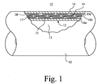
- Figure 1 illustrates a cross sectional view of a portion of flexible pipe 10. It will be understood that the longitudinal length of the flexible pipe can be from a few metres to a few kilometres or more in length.
- An innermost fluid retaining layer 11 has an inner surface 12 which defines a central bore 13 along which fluid can flow.
- the flexible pipe is applicable to the transportation of a wide variety of fluids such as water or production fluids such as oil or gas.
- One or more inner layers may be provided under the fluid retaining layer.
- An outer sheath 14 provides an outer protection layer which prevents ingress of contaminants as well as providing physical protection against attack from an environment 15 outside the flexible pipe.
- Three layers 16a, 16b, 16c of armour protection are formed between an outer surface 17 of the fluid retaining layer and an inner surface 18 of the outer sheath 14.
- An annular region 19 is thus formed between the inner surface 18 of the outer sheath and outer surface 17 of the fluid retaining layer 11.
- armour layer 16 may be provided by one or more layers of wound strip according to further embodiments of the present invention. Also whilst the strips illustrated in Figure 1 are shown as having a substantially flat cross section, it will be understood that strip having predetermined cross sections may be used according to further embodiments of the present invention. Such strips may or may not interlock to some extent.
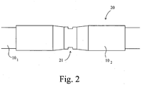
- Figure 2 illustrates how a pipeline 20 can be formed by joining portions of pipeline 10 1 , 10 2 together in an end-to-end configuration via a mid-line connector 21. It will be understood that a pipeline may be formed by two or more portions of flexible pipe 10 1,2 ....n each joined to one or two adjacent portions of flexible pipe by a respective connection.
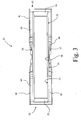
- FIG. 3 illustrates a connector 21 useable to secure adjacent portions of flexible pipe together in more detail.
- the connector includes an inner cylindrical tube 30 having a substantially cylindrical inner surface 31 and an outer surface 32 which is inwardly tapered at a first open end 33 and a further open end 34. The taper helps locate the pipe ends with respect to the connector during connection.
- a central region of the outer surface of the tube is stepped outwardly to form a raised central section 35.
- the raised portion 35 is itself stepped radially outwardly at one end 36 to form an abutment surface 37.
- a ring 38 Prior to securing to a flexible pipe a ring 38 is slipped over the first end 33 of the tube 30.
- the ring has an inner diameter provided by an inner cylindrical surface 38 having a dimension just big enough to slip over the outer diameter of the narrow end of the outer surface 35 of the raised portion of the tube.
- An end 39 of the ring abuts with the surface 37 of the wide end of the raised portion 35. This duly locates the ring in position.
- the ring 38 has a central cut out region to aid handling. Other profiles of ring may be utilised as discussed hereinbelow.
- a first jacket 40 and further jacket 41 are secured to the connecting ring via a weldment, adhesive, bolt or screw or other such fastening mechanism.
- Each jacket has a respective open mouth 42, 43 and is generally cylindrical in shape with an inwardly tapered end which tapers radially inwardly at one end of the jacket.
- an annulus region is defined at each end of the midline connector.
- the annular region 44 at a first end of the connector is defined between an outer surface of the cylindrical tube and an inner surface of a respective jacket 40.
- a further annulus region 45 is defined between an outer surface of a further end of the tube and an inner surface of a remaining jacket 41. It will be understood that the jackets may be secured to other locations of the connector 21.
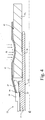
- Figure 4 illustrates how an end of a flexible pipe 10 2 may be secured at one end of the midline connector 21 between a jacket 41 secured to the ring 38 mounted on the midline connector 21. Subsequent to securing the jacket 41 to the connector ring via the weldment 46 or other such fastening, an end of the flexible pipe 10 2 is introduced into the annulus region 45. Subsequently during a swaging process the jacket 41 is deformed by a force exerted as shown by arrow A in Figure 4 which locks the pipe end in the connector. It will be appreciated that other fastening techniques, such as bolting, gluing, welding or the like, may be utilised to secure the end of the flexible pipe to the jacket 41 and tube 30.
- fastening techniques such as bolting, gluing, welding or the like, may be utilised to secure the end of the flexible pipe to the jacket 41 and tube 30.
- an open end of the flexible pipe is thus in fluid communication with a space 47 which is a part of the annular region between the jacket and cylindrical body 30.
- the annular region formed between the outer surface 17 of the fluid retaining layer and inner surface 18 of the outer sheath will vent directly into this space 47.
- From there fluid flow occurs via passageways formed as bores or slits through the cylindrical body 30 and/or ring 38 to a corresponding space at the other end of the midline connector. From there fluid venting from one flexible pipe can pass into the corresponding annular region of the adjacent flexible pipe portion.
- FIG. 5 illustrates a further view of a midline connector 21 before jackets are attached.
- the connector has a cylindrical body 30 having a substantially cylindrical inner surface 31 which defines an internal bore along which fluid can flow through the connector and along the pipeline in general.
- the outer surface 32 of the connector is tapered inwardly towards a first open end to thereby define an inwardly extending region 50 extending circumferentially around the body.
- a further circumferentially extending tapered region 51 is formed.
- a central region of the outer surface of the cylindrical body is stepped radially outwardly at a first end 52 to provide a raised outer surface which is generally cylindrical. This extends to a further end region 36 of the central raised section 35 of the connector.
- an end 52 of the raised section thus extends radially outwardly less than the other end 36 of the raised section.
- a ring 38 is slid over the central raised region from the first end 52 and along the raised section until the ring abuts with the radially outwardly extending step at the further end of the raised region. This duly locates the ring in position.
- slits 55 are formed in the raised central section of the connector.
- One or more slits can be preformed and as illustrated in Figure 5 the slits extend across the whole width of the central raised section. It will be appreciated that the slits may be formed less than the whole way through the raised portion according to further embodiments of the present invention.
- the ring 38 covers a central region of each of the slits when duly located.
- Figure 6 illustrates the raised central portion of the connector and the slits 55 prior to the ring being put in position.
- Figure 6 also illustrates how an outer surface of the raised central section is stepped.
- the slits 55 provide a vent passage along which fluid such as gas or liquid can flow when the pipeline is in operation.
- the vent passage can, instead of a slit, be formed as a through bore or partial through bore through the raised central section of the connector.
- Still further alternative embodiments include one or more slits or bores formed at one or more predetermined locations on the ring which communicate with partial mating passages formed by slits or bores in the raised central region of the connector.
- the raised central region of the connector may be integrally formed with the cylindrical body as illustrated in Figures 5 and 6 or alternatively may be a separate unitary or multi-piece unit secured to the cylindrical body prior to application of the ring.
- Figure 7 illustrates an alternative embodiment of the connector shown in Figure 6 and illustrates how the slots 55 may be alternatively formed as curved or labyrinthine passageways through the raised section.
- the curved slot 70 illustrated in Figure 7 is shown passing the whole way through the raised section in the middle of the connector alternative embodiments of the present invention can make use of one or more curved slots which pass only a partial way through the raised portion.
- Embodiments of the present invention eliminate flanged or welded end fittings for the purpose of connecting two sections of flexible pipe together.
- the connector is installed as a coupling that reduces leak potential caused by two flanged end fittings which would otherwise be used according to the prior art.
- the midline connector also eliminates the need for welding two separate end fittings together as per the prior art.
- the connector "grabs" two ends of flexible pipe from the inner and outer diameters.
- the tubular body contacts an inner diameter of each flexible pipe and a centring ring is used to hold the connector during a swaging operation.
- External jackets are welded to the centring ring and these can be used to grab the outer diameter of the flexible pipe.
- Venting is incorporated between the inner body and centring ring by means of slots or other types of passage.
- the slots can be cut axially along a section of the body outer diameter or alternatively can be helically formed. Slots may be on the raised portion of the cylindrical body and/or an inner surface of the ring.
- the body and centring ring are concentrically mated together and form vent paths completely enclosed within the midline connector.
- Slots machined on the outer diameter of the body may alternatively take the form of a helix or labyrinthine structure wrapping around the raised surface of the body outer diameter. This is advantageous during a manufacturing process as lathes may be used to machine the body without independent milling capabilities.
- Alternative embodiments of the present invention utilise a design which includes mating the body and centring ring by loose fitting threads which allow gases to pass through the helical gaps in the threads.
- Figure 8 illustrates alternative cross sectional views of a centring ring 38.
- Figure 8b illustrates the cross section of ring illustrated in the previous drawings.
- Figure 8a illustrates a substantially cylindrical ring with a radially outwardly stepped raised portion 81 at a predetermined end. As shown in Figure 8b the outer surface of the ring may alternatively have a raised portion 82, 83 at each longitudinal end.
- Figure 8c illustrates a raised portion 84 which extends radially outwardly from a substantially cylindrical body within the ends of the ring but offset from a central point.
- Figure 8d illustrates how a substantially cylindrical ring may be utilised. It will be appreciated that further cross sections of ring may be utilised according to still further embodiments of the present invention.
- Prior art connections for securing flexible pipe together have transmitted gases between two separate sections of flexible pipe by incorporating external components connected to end fittings. These external components, such as jumper tubes, were connected to jackets or other portions of a connector by either welding or threading components.
- the present invention eliminates all external components and the process of connecting external components to end fittings.
- the internal nature of the venting provided by embodiments of the present invention provides a more direct path for the gas transmittal, thus reducing the possibility of an obstructed path. Pressure build-up within annulus spaces caused by blocked gas can cause rupture of the outer shield layer of the flexible pipe and this is avoided according to embodiments of the present invention.
- the midline connection is thus a multi-part system that "grabs" two ends of flexible pipe from the inner and outer diameters.
- the midline connection includes an inner body formed as a tube that contacts an inner diameter of the pipe.
- a centring ring is used to hold the midline connection during a swaging operation and external jackets are welded to the centring ring. These external jackets are used to grab an outer diameter of each flexible pipe.
Landscapes
- Engineering & Computer Science (AREA)
- General Engineering & Computer Science (AREA)
- Mechanical Engineering (AREA)
- Rigid Pipes And Flexible Pipes (AREA)
- Quick-Acting Or Multi-Walled Pipe Joints (AREA)
- Lining Or Joining Of Plastics Or The Like (AREA)
- Joints Allowing Movement (AREA)
Priority Applications (1)
| Application Number | Priority Date | Filing Date | Title |
|---|---|---|---|
| PL09761992T PL2304299T3 (pl) | 2008-06-09 | 2009-03-24 | Elastyczne złącze rurowe |
Applications Claiming Priority (2)
| Application Number | Priority Date | Filing Date | Title |
|---|---|---|---|
| US6004908P | 2008-06-09 | 2008-06-09 | |
| PCT/GB2009/050272 WO2009150443A1 (en) | 2008-06-09 | 2009-03-24 | Flexible pipe joint |
Publications (2)
| Publication Number | Publication Date |
|---|---|
| EP2304299A1 EP2304299A1 (en) | 2011-04-06 |
| EP2304299B1 true EP2304299B1 (en) | 2017-10-04 |
Family
ID=40875213
Family Applications (1)
| Application Number | Title | Priority Date | Filing Date |
|---|---|---|---|
| EP09761992.8A Active EP2304299B1 (en) | 2008-06-09 | 2009-03-24 | Flexible pipe joint |
Country Status (14)
| Country | Link |
|---|---|
| US (5) | US9625070B2 (es) |
| EP (1) | EP2304299B1 (es) |
| CN (1) | CN102057202A (es) |
| AU (1) | AU2009259081B2 (es) |
| BR (1) | BRPI0914973B1 (es) |
| CA (1) | CA2727323C (es) |
| CO (1) | CO6382186A2 (es) |
| DK (1) | DK2304299T3 (es) |
| EA (1) | EA020249B1 (es) |
| MX (2) | MX2010013584A (es) |
| MY (1) | MY154099A (es) |
| NO (1) | NO2304299T3 (es) |
| PL (1) | PL2304299T3 (es) |
| WO (1) | WO2009150443A1 (es) |
Families Citing this family (19)
| Publication number | Priority date | Publication date | Assignee | Title |
|---|---|---|---|---|
| CA2727323C (en) | 2008-06-09 | 2014-06-03 | Prime Flexible Products, Inc. | Flexible pipe joint |
| EA030167B1 (ru) * | 2011-10-04 | 2018-06-29 | Флексстил Пайплайн Текнолоджиз, Инк. | Концевой фитинг трубы с улучшенной вентиляцией |
| CN103133801A (zh) * | 2011-11-23 | 2013-06-05 | 上海市基础工程有限公司 | 海底管道和光电缆埋设装置进水旋铰接头 |
| CN104114806B (zh) | 2011-11-29 | 2017-05-10 | 通用电气石油和天然气英国有限公司 | 用于向柔性管提供浮力和弯曲支承的组件及其设置方法 |
| GB201120534D0 (en) | 2011-11-29 | 2012-01-11 | Wellstream Int Ltd | Buoyancy element and method |
| DE102012204372A1 (de) * | 2012-03-20 | 2013-09-26 | Siemens Aktiengesellschaft | Verbindungsvorrichtung und elektrische Schaltanlage |
| US9033614B2 (en) | 2013-05-29 | 2015-05-19 | Ge Oil & Gas Uk Limited | Pipe components and methods of manufacture |
| EP3201509B1 (en) | 2014-09-30 | 2020-01-01 | Flexsteel Pipeline Technologies, Inc. | Connector for pipes |
| CN106321926A (zh) * | 2015-06-30 | 2017-01-11 | 周荣建 | 一种消防龙头 |
| NL1041958B1 (en) * | 2016-06-29 | 2018-01-05 | Wavin Bv | Press fitting device |
| CN106287065A (zh) * | 2016-09-12 | 2017-01-04 | 周杰 | 一种风管机用直管快速接头 |
| BR102017011388B1 (pt) | 2017-05-30 | 2021-08-03 | Petróleo Brasileiro S/A - Petrobras | Conector de tubo flexível adaptado para realizar o controle e circulação forçada de fluidos anticorrosivos pelo anular do tubo flexível |
| US10753512B1 (en) * | 2019-03-28 | 2020-08-25 | Trinity Bay Equipment Holdings, LLC | System and method for securing fittings to flexible pipe |
| US20210207747A1 (en) * | 2020-01-07 | 2021-07-08 | Trinity Bay Equipment Holdings, LLC | Re-deployable pipe fitting systems and methods |
| US11098853B1 (en) * | 2020-02-19 | 2021-08-24 | Trinity Bay Equipment Holdings, LLC | Pipeline supplemental containment wall systems and methods |
| CN111456167B (zh) * | 2020-04-17 | 2021-02-26 | 安徽中控建设工程有限公司 | 一种具有舒张功能的建筑给排水装置 |
| US11065669B1 (en) * | 2020-05-28 | 2021-07-20 | Trinity Bay Equipment Holdings, LLC | Forward stroke pipe fitting swage machine systems and methods |
| US11065670B1 (en) * | 2020-05-28 | 2021-07-20 | Trinity Bay Equipment Holdings, LLC | Outward direction pipe fitting swage machine systems and methods |
| US11193615B1 (en) | 2021-02-25 | 2021-12-07 | Trinity Bay Equipment Holdings, LLC | Multi-annuli pipe fitting systems and methods |
Family Cites Families (180)
| Publication number | Priority date | Publication date | Assignee | Title |
|---|---|---|---|---|
| US866852A (en) * | 1906-05-14 | 1907-09-24 | Petter Eriksson | Core-pressing apparatus. |
| US2338581A (en) * | 1942-01-05 | 1944-01-04 | Phillips Petroleum Co | Catalytic process |
| GB866852A (en) | 1959-03-04 | 1961-05-03 | Amalgamated Limestone Corp Ltd | Improvements in or relating to hose pipes |
| US3574355A (en) * | 1968-09-24 | 1971-04-13 | Hans Oetiker | Hose connection |
| US3724882A (en) * | 1971-05-10 | 1973-04-03 | Ford Motor Co | Tube-to-hose connection |
| US3702707A (en) * | 1971-06-23 | 1972-11-14 | Jose Rosan Sr | Fittings for high pressure fluid lines |
| US4854613A (en) * | 1988-01-27 | 1989-08-08 | Rexnord Holdings Inc. | Composite connecting member for hydraulic fluid lines |
| US4863197A (en) * | 1988-03-03 | 1989-09-05 | Ingersol-Rand Company | High-pressure end fitting |
| JPH0399294A (ja) | 1989-09-12 | 1991-04-24 | Seiko Epson Corp | 電子時計 |
| JPH0399294U (es) * | 1989-11-08 | 1991-10-16 | ||
| US5072072A (en) * | 1990-03-23 | 1991-12-10 | Thomas & Betts Corporation | Electrical connector for liquidtight conduit |
| DE4013512A1 (de) | 1990-04-27 | 1991-10-31 | Black & Decker Inc | Schalteinrichtung zum umschalten eines kraftgetriebenen werkzeugs |
| US5123677A (en) * | 1990-05-31 | 1992-06-23 | Swagelok-Quick Connect Co. | All plastic quick-connect coupling |
| DE9016310U1 (de) * | 1990-11-30 | 1991-02-21 | Hewing GmbH, 4434 Ochtrup | Rohrverbindung, insbesondere an Verbundrohren |
| US5456502A (en) | 1991-04-04 | 1995-10-10 | Sharp; Bruce R. | Fittings for use with fin strengthened double wall pipeline systems |
| US5259651A (en) | 1991-04-04 | 1993-11-09 | Sharp Bruce R | Double wall fittings for use with double wall pipeline systems |
| US5547231A (en) * | 1991-04-04 | 1996-08-20 | Sharp; Bruce R. | Fittings for use with double wall pipeline systems having support fins |
| US5449203A (en) | 1991-04-04 | 1995-09-12 | Sharp; Bruce R. | Fittings for connection to double wall pipeline systems |
| CH682942A5 (de) * | 1991-04-22 | 1993-12-15 | Geberit Ag | Verbindungsteil für eine Pressverbindung. |
| US5215336A (en) * | 1991-06-28 | 1993-06-01 | Shur-Lok Corporation | Coupling joint assembly with integral retention mechanism |
| DE9110998U1 (de) * | 1991-09-05 | 1991-10-31 | Hewing GmbH, 4434 Ochtrup | Rohrverbindung |
| US5224738A (en) * | 1992-03-27 | 1993-07-06 | Jun Taga | Double piping structure |
| US5361806A (en) * | 1992-07-07 | 1994-11-08 | Titeflex Corporation | Kevlar reinforced high pressure hose assembly with grip and environmental barrier |
| JP3431052B2 (ja) | 1995-08-18 | 2003-07-28 | サンコー瓦斯精機株式会社 | 金属フレキシブル管用継手 |
| CN2338581Y (zh) | 1997-07-18 | 1999-09-15 | 沈仲山 | 一种软管连接器 |
| US6139617A (en) * | 1997-09-08 | 2000-10-31 | Kerr-Mcgee Chemical Llc | Titanium dioxide pigments |
| DE29900796U1 (de) * | 1998-04-03 | 1999-04-08 | Geberit Technik Ag, Jona | Vorrichtung zum Verbinden eines Rohrstutzens, rohrförmigen Armaturenteils oder Fittings mit einem Rohr |
| DE10006044A1 (de) | 2000-02-10 | 2001-08-16 | Roche Diagnostics Gmbh | Anordnung und Verfahren zur Dosierung eines die Blutglukose eines Patienten regulierenden Hormons |
| US6394504B1 (en) * | 2000-04-04 | 2002-05-28 | General Motors Corporation | Clampless fluid transfer hose coupling |
| DE50001805D1 (de) * | 2000-09-04 | 2003-05-22 | Knipping Daniel | Vorrichtung zur Herstellung einer unlösbaren Verbindung zwischen dem Endbereich eines Rohres und einem Verbindungselement |
| US6523862B1 (en) * | 2001-03-14 | 2003-02-25 | James MacDuff | Tubing connector with integrated crimp ring and reaming tool for use therewith |
| US6737584B2 (en) * | 2001-05-01 | 2004-05-18 | Bridgeport Fittings, Inc. | Electrical cable connector |
| DE10130858A1 (de) * | 2001-06-28 | 2003-01-16 | Markus Schmidt | Schiebehülsenverbindung für Rohrleitungen |
| ITMI20022716A1 (it) * | 2002-12-20 | 2004-06-21 | Faster Spa | Innesto rapido con possibilita' di aggancio, rispettivamente |
| WO2006064284A1 (en) | 2004-12-13 | 2006-06-22 | Smart Pipe Company, Lp | Systems and methods for making pipe liners |
| EP1731823A1 (en) * | 2005-06-08 | 2006-12-13 | Single Buoy Moorings Inc. | Cryogenic transfer hose |
| US7946629B2 (en) * | 2005-10-07 | 2011-05-24 | Flexpipe Systems Inc. | Pipe coupling and method for installation |
| BRPI0720487B8 (pt) | 2006-12-22 | 2020-12-01 | Nat Oilwell Varco Denmark Is | tubo flexível |
| WO2008113362A1 (en) | 2007-03-16 | 2008-09-25 | Nkt Flexibles I/S | A flexible pipe |
| FR2915552B1 (fr) | 2007-04-27 | 2009-11-06 | Technip France | Conduite tubulaire flexible pour le transport d'hydrocarbures gazeux. |
| US8714206B2 (en) | 2007-12-21 | 2014-05-06 | Shawcor Ltd. | Styrenic insulation for pipe |
| FR2928437B1 (fr) | 2008-03-07 | 2011-08-19 | Technip France | Methode et installation de montage d'un embout de raccordement |
| CA2727323C (en) | 2008-06-09 | 2014-06-03 | Prime Flexible Products, Inc. | Flexible pipe joint |
| FR2932870B1 (fr) | 2008-06-18 | 2010-06-18 | Inst Francais Du Petrole | Conduite avec gaine a permeabilite reduite aux composes acides |
| CA2647972A1 (en) | 2008-12-19 | 2010-06-19 | Shawcor Ltd. | Method of filling a casing |
| US8485229B2 (en) | 2008-12-22 | 2013-07-16 | Shawcor Ltd. | Wrappable styrenic pipe insulations |
| FR2954451B1 (fr) | 2009-12-21 | 2012-03-02 | Technip France | Conduite flexible sous-marine comprenant une couche comprenant une resine polyamide comprenant un silsesquioxane oligomerique polyedrique |
| EP2519764B1 (en) | 2009-12-28 | 2019-06-12 | National Oilwell Varco Denmark I/S | An unbonded, flexible pipe |
| EP2360406B1 (de) | 2010-02-08 | 2019-01-02 | Pipelife Austria GmbH & Co. KG | Rohr mit einer Steckmuffe mit Stützring |
| FR2957293B1 (fr) | 2010-03-09 | 2012-03-09 | Technip France | Installation d'extrusion d'une gaine en matiere plastique |
| NL2004694C2 (en) | 2010-05-10 | 2011-11-14 | Draka Comteq Bv | An assembly comprising at least one duct and at least one distribution box, and a method of mounting a distribution box to a duct. |
| CA2704406A1 (en) | 2010-05-19 | 2011-11-19 | Shawcor Ltd. | Casing member for forming a connection between tubular sections and use thereof for forming connections |
| EP2576333B1 (en) | 2010-06-04 | 2019-08-07 | National Oilwell Varco Denmark I/S | A flexible pipe system |
| GB2481621B (en) | 2010-06-30 | 2015-09-23 | Polypipe Ltd | Drainage pipes |
| FR2962548B1 (fr) | 2010-07-08 | 2012-08-17 | Inst Francais Du Petrole | Procede de controle de l'integrite d'une conduite tubulaire flexible et dispositif pour sa mise en ?uvre |
| GB201020514D0 (en) | 2010-12-03 | 2011-01-19 | Magma Global Ltd | Composite pipe |
| US9523446B2 (en) | 2011-01-06 | 2016-12-20 | National Oilwell Varco Denmark I/S | Unbonded flexible pipe |
| GB201100585D0 (en) | 2011-01-14 | 2011-03-02 | Magma Global Ltd | Connector arrangement for composite pipe |
| NO2665959T3 (es) | 2011-01-20 | 2018-05-26 | ||
| US9163296B2 (en) | 2011-01-25 | 2015-10-20 | Tenaris Coiled Tubes, Llc | Coiled tube with varying mechanical properties for superior performance and methods to produce the same by a continuous heat treatment |
| FR2971762B1 (fr) | 2011-02-22 | 2015-05-01 | Technip France | Systeme de transfert d'un fluide, notamment du gaz de petrole liquefie entre une premiere installation de surface et une deuxieme installation de surface |
| NL2006335C2 (en) | 2011-03-03 | 2012-09-04 | Airborne Composites Tubulars B V | Method for manufacturing continuous composite tube, apparatus for manufacturing continuous composite tube. |
| FR2975164B1 (fr) | 2011-05-10 | 2013-06-21 | Technip France | Dispositif et procede d'isolation thermique d'une zone de raccordement d'embouts de connexion de deux conduites sous-marines calorifugees. |
| WO2012155912A1 (en) | 2011-05-13 | 2012-11-22 | National Oilwell Varco Denmark I/S | An unbonded flexible pipe and pipe system |
| US9470347B1 (en) * | 2011-06-08 | 2016-10-18 | AGS I-Prop., LLC | Fluid line connector |
| BR112013032388B1 (pt) | 2011-06-17 | 2020-09-29 | National Oilwell Varco Denmark I / S | Tubo flexível não unido para aplicações fora da costa, e, uso de aço manganês |
| FR2978489B1 (fr) | 2011-07-29 | 2013-07-05 | IFP Energies Nouvelles | Conduite flexible avec tube d'injection et procede de transport d'un effluent petrolier |
| EA030167B1 (ru) * | 2011-10-04 | 2018-06-29 | Флексстил Пайплайн Текнолоджиз, Инк. | Концевой фитинг трубы с улучшенной вентиляцией |
| AR088889A1 (es) | 2011-11-16 | 2014-07-16 | Flexpipe Systems Inc | Tuberia reforzada flexible y cinta de refuerzo |
| SA112340031B1 (ar) | 2011-11-28 | 2016-06-11 | مجموعة فيوتشر بايب الصناعية المحدودة (سابقا بإسم فيوتشر بايب المحدودة) | طرق وأنظمة توصيل أنبوب ألياف زجاجية |
| CA2859433C (en) | 2011-12-23 | 2019-03-26 | Prysmian S.P.A. | Cable comprising an element indicating water infiltration and method using said element |
| WO2013120201A1 (en) | 2012-02-17 | 2013-08-22 | 8193053 Canada Ltd. | Pipe, pipe connection and pipeline system |
| FR2987667B1 (fr) | 2012-03-01 | 2014-03-07 | Technip France | Structure tubulaire flexible d'exploitation petroliere a haute tenue |
| JP6301308B2 (ja) | 2012-03-26 | 2018-03-28 | ソルベイ スペシャルティ ポリマーズ イタリー エス.ピー.エー. | フルオロポリマーパイプ |
| US9303463B2 (en) | 2012-06-06 | 2016-04-05 | National Oilwell Varco Denmark I/S | Riser and an offshore system |
| EP2870397B1 (en) | 2012-07-06 | 2019-09-11 | National Oilwell Varco Denmark I/S | An unbonded flexible pipe |
| GB2503880B (en) | 2012-07-09 | 2019-03-13 | Polypipe Ltd | Insert for pipes |
| FR2994241B1 (fr) | 2012-08-03 | 2015-03-06 | Technip France | Conduite flexible sous marine comprenant une couche comprenant un polyethylene a resistance thermique accrue |
| FR2996280B1 (fr) | 2012-09-28 | 2014-09-26 | Technip France | Conduite tubulaire flexible instrumentee |
| FR3000170B1 (fr) | 2012-12-21 | 2016-04-29 | Technip France | Embout de connexion d'une conduite flexible de transport de fluide et procede associe |
| GB2562674B (en) | 2013-02-08 | 2019-03-06 | Polypipe Ltd | Mechanical ventilation and heat recovery unit and system |
| FR3002611B1 (fr) | 2013-02-25 | 2015-08-14 | Technip France | Conduite flexible pour le transport des hydrocarbures a gaine d'etancheite externe renforcee |
| AU2014261820B2 (en) | 2013-05-02 | 2018-07-26 | National Oilwell Varco Denmark I/S | An assembly of a flexible pipe and an end-fitting |
| FR3007494B1 (fr) | 2013-06-24 | 2016-02-05 | Technip France | Embout de connexion d'une conduite flexible, conduite flexible et procede associes |
| BR112016001932B1 (pt) | 2013-08-02 | 2020-09-24 | National Oilwell Varco Denmark I/S | Tubo flexível não unido para transporte de fluidos, e, sistema fora da costa |
| FR3009856B1 (fr) | 2013-08-22 | 2015-08-21 | Technip France | Procede de fabrication d'une conduite tubulaire flexible |
| GB2518006A (en) | 2013-09-10 | 2015-03-11 | Magma Global Ltd | Heating method |
| WO2015070871A1 (en) | 2013-11-12 | 2015-05-21 | National Oilwell Varco Denmark I/S | An assembly comprising an unbonded flexible pipe and an end-fitting |
| GB2520756B (en) | 2013-11-29 | 2019-10-09 | Polypipe Ltd | Manifold for use with a ventilation system |
| FR3014165B1 (fr) | 2013-12-03 | 2015-11-13 | IFP Energies Nouvelles | Embout de connexion d'une conduite flexible avec ancrage des fils d'armure par coincement |
| FR3014995B1 (fr) | 2013-12-12 | 2016-08-12 | Technip France | Embout de connexion d'une conduite flexible, dispositif et procede associes |
| US10288207B2 (en) | 2013-12-20 | 2019-05-14 | Smart Pipe Company, Inc. | In line inspection method and apparatus for performing in line inspections |
| FR3016020B1 (fr) | 2013-12-30 | 2016-05-20 | Technip France | Methode de montage d'un embout de fixation d'une conduite tubulaire flexible et installation de mise en œuvre |
| FR3017438B1 (fr) | 2014-02-11 | 2016-10-14 | Technip France | Conduite flexible de transport de fluide et procede associe |
| FR3017439B1 (fr) | 2014-02-13 | 2016-10-14 | Technip France | Conduite flexible de transport de fluide munie d'un insert en forme de s etendu et procede de fabrication associe |
| US10197198B2 (en) | 2014-03-21 | 2019-02-05 | National Oilwell Varco Denmark I/S | Flexible pipe |
| FR3020859B1 (fr) | 2014-05-06 | 2016-06-24 | Technip France | Conduite flexible non liee de transport d'un materiau abrasif, procede et utilisation associes |
| BR102014023265B1 (pt) | 2014-09-19 | 2021-05-04 | Technip France | método de calibração para uma tubulação flexível |
| EP3209922B1 (en) | 2014-10-20 | 2022-01-19 | National Oilwell Varco Denmark I/S | An assembly comprising an end-fitting and an unbonded flexible pipe |
| US10471661B2 (en) | 2014-10-24 | 2019-11-12 | Shawcor, Ltd. | Apparatus and system for electro-fusion of polyethylene pipeline |
| US10487965B2 (en) | 2014-10-28 | 2019-11-26 | Core Linepipe Inc. | Pipe manipulation apparatus and methods |
| EP3021026B1 (en) | 2014-11-12 | 2018-07-11 | Pipelife Nederland B.V. | High pressure pipe coupling construction |
| AU2015345613B2 (en) | 2014-11-13 | 2019-10-03 | National Oilwell Varco Denmark I/S | A method of installing an unbonded flexible pipe |
| FR3028913B1 (fr) | 2014-11-24 | 2016-12-09 | Technip France | Couche d'isolation thermique pour conduite tubulaire flexible sous-marine |
| FR3030011B1 (fr) | 2014-12-11 | 2016-12-30 | Technip France | Procede de montage d'un embout de connexion d'une conduite tubulaire flexible et dispositif permettant de mettre en oeuvre ce procede |
| FR3031186B1 (fr) | 2014-12-30 | 2017-02-10 | Technip France | Procede de controle d'une ligne flexible et installation associee |
| EP3059481B1 (en) | 2015-02-17 | 2019-08-28 | Pipelife Nederland B.V. | High pressure pipe and use thereof |
| CN107735200A (zh) | 2015-03-20 | 2018-02-23 | 肖克有限公司 | 便携式管车床和方法 |
| AT15019U1 (de) | 2015-04-16 | 2016-11-15 | Pipelife Austria Gmbh & Co Kg | Steckmuffenverbindung für Rohre aus thermoplastischem Material |
| US10234068B2 (en) | 2015-04-20 | 2019-03-19 | Shawcor, Ltd. | Foamed insulation coating on pipes and methods therefor |
| FR3035171B1 (fr) | 2015-04-20 | 2017-05-19 | Technip France | Procede de realisation d'une etancheite dans un embout d'une conduite flexible comprenant une gaine de pression |
| US10429267B2 (en) | 2015-06-23 | 2019-10-01 | Dura-Line Corporation | Pipe assembly |
| FR3038033B1 (fr) | 2015-06-29 | 2017-07-28 | Technip France | Methode de montage d'embout de conduite flexible |
| CA2995257C (en) | 2015-08-10 | 2023-08-22 | National Oilwell Varco Denmark I/S | An assembly comprising an end-fitting and an unbonded flexible pipe |
| US10962148B2 (en) | 2015-08-10 | 2021-03-30 | National Oilwell Varco Denmark I/S | Method of testing an unbonded flexible pipe |
| WO2017025098A1 (en) | 2015-08-10 | 2017-02-16 | National Oilwell Varco Denmark I/S | An unbonded flexible pipe |
| BR112018002663B1 (pt) | 2015-08-10 | 2021-08-31 | National Oilwell Varco Denmark I/S | Tubo flexível não ligado |
| NL2015434B1 (en) | 2015-09-14 | 2017-03-29 | Pipelife Nederland Bv | High pressure pipe and method for producing such pipe. |
| HU230824B1 (hu) | 2015-10-21 | 2018-07-30 | Contitech Rubber Industrial Kft. | Vegyszer- és gázálló nagynyomású, nagy átmérőjű, kötött szerkezetű gumi flexibilis vezeték, és eljárás annak előállítására |
| FR3042840B1 (fr) | 2015-10-27 | 2018-07-06 | Technip France | Methode de mise en pression de l'espace interne d'ecoulement d'une conduite flexible destinee au transport d'hydrocarbures |
| BR112018008584B1 (pt) | 2015-11-03 | 2021-08-31 | National Oilwell Varco Denmark I/S | Tubo flexível não ligado para o transporte submarino de fluidos |
| FR3046449B1 (fr) | 2015-12-30 | 2018-02-16 | Technip France | Procede d'assemblage d'un premier troncon de conduite flexible avec un deuxieme troncon de conduite flexible, et conduite flexible associee |
| FR3046452B1 (fr) | 2015-12-31 | 2018-02-16 | Technip France | Embout de connexion d'une ligne flexible, dispositif de mesure et procede associe |
| BR112018016426B1 (pt) | 2016-02-15 | 2022-08-30 | National Oilwell Varco Denmark I/S | Conjunto e método para a redução de corrente de fuga |
| WO2017165297A1 (en) | 2016-03-21 | 2017-09-28 | Molex, Llc | Leak sensor assemblies and systems utilizing same |
| GB2548825A (en) | 2016-03-24 | 2017-10-04 | Magma Global Ltd | Pinned composite pipe end-fitting |
| FR3050005B1 (fr) | 2016-04-06 | 2018-05-04 | Technip France | Conduite sous-marine comprenant une gaine comprenant un homopolymere de polypropylene |
| FR3051241B1 (fr) | 2016-05-10 | 2018-10-12 | Technip France | Dispositif chauffant pour le transport d'un melange multiphasique d'hydrocarbures et procede associe |
| DE102016208115A1 (de) | 2016-05-11 | 2017-11-16 | Contitech Mgw Gmbh | Verfahren zur Herstellung eines Ladeluftrohres |
| DE102016208116A1 (de) | 2016-05-11 | 2017-11-16 | Contitech Mgw Gmbh | Verfahren zur Herstellung eines Ladeluftrohres |
| EP3458531A4 (en) | 2016-05-17 | 2020-05-06 | Shawcor Ltd. | COATING COMPOSITIONS AND METHODS OF PREPARING THE SAME |
| DE102016209005A1 (de) | 2016-05-24 | 2017-12-14 | Contitech Schlauch Gmbh | Mehrschichtiger flexibler Schlauch |
| FR3052530B1 (fr) | 2016-06-13 | 2019-05-31 | Technip France | Embout de connexion de ligne flexible, ligne flexible et procede associes |
| CA3026966A1 (en) | 2016-06-13 | 2017-12-21 | Shawcor Ltd. | Apparatus for coating pipes |
| NL2016989B1 (nl) | 2016-06-17 | 2018-01-16 | Pipelife Nederland Bv | Trekvast koppelstuk |
| NL1041958B1 (en) * | 2016-06-29 | 2018-01-05 | Wavin Bv | Press fitting device |
| EP3482112B1 (en) | 2016-07-06 | 2023-08-16 | National Oilwell Varco Denmark I/S | A flexible armoured pipe with a retaining layer of metal elongate strip |
| DE102016213148A1 (de) | 2016-07-19 | 2018-01-25 | Contitech Mgw Gmbh | Stützhülse |
| AU2017302735B2 (en) | 2016-07-25 | 2023-04-06 | National Oilwell Varco Denmark I/S | Detecting parameter in flexible pipe system comprising a turret |
| GB2553319B (en) | 2016-09-01 | 2018-12-26 | Technip France | Mechanically lined pipe having an inner polymer liner |
| FR3055685B1 (fr) | 2016-09-02 | 2019-06-14 | Technip France | Element d'armure d'une ligne flexible destinee a etre placee dans une etendue d'eau, et ligne flexible associee |
| GB2557571B (en) | 2016-09-16 | 2019-09-11 | Technip France | Method of installing an in-line structure in a pipeline |
| BR112019007789B1 (pt) | 2016-10-17 | 2023-01-24 | National Oilwell Varco Denmark I/S | Instalação offshore |
| WO2018094519A1 (en) | 2016-11-24 | 2018-05-31 | Shawcor Ltd. | Pvdf coated pipe for oil or gas applications |
| DE102016223618A1 (de) | 2016-11-29 | 2018-05-30 | Contitech Schlauch Gmbh | Mehrschichtiger flexibler Schlauch |
| FR3046208B1 (fr) | 2016-12-22 | 2018-11-16 | IFP Energies Nouvelles | Conduite flexible de transport de fluide petrolier comprenant une barriere contre la diffusion |
| BR112019013850B1 (pt) | 2017-01-13 | 2022-08-30 | National Oilwell Varco Denmark I/S | Tubo flexível não ligado e instalação offshore |
| FR3062211B1 (fr) | 2017-01-24 | 2021-12-24 | Technip France | Procede de controle non destructif d'une ligne flexible et dispositif de controle non destructif associe |
| WO2018149462A1 (en) | 2017-02-20 | 2018-08-23 | National Oilwell Varco Denmark I/S | An assembly comprising an end-fitting and an unbonded flexible pipe |
| US10247337B2 (en) | 2017-03-20 | 2019-04-02 | Contitech Usa, Inc. | Hose end construction and fitting |
| FR3064711B1 (fr) | 2017-03-31 | 2019-04-12 | IFP Energies Nouvelles | Conduite flexible avec nappes d'armures metalliques et nappes d'armures composites |
| US10415731B2 (en) | 2017-04-10 | 2019-09-17 | Contitech Usa, Inc. | Six sided forged ferrule staking crimped fitting and method of manufacture thereof |
| US10458573B2 (en) | 2017-04-10 | 2019-10-29 | Contitech Usa, Inc. | High pressure compact spiral hydraulic hose |
| GB2563645B (en) | 2017-06-22 | 2020-03-11 | Magma Global Ltd | End fitting for a composite pipe |
| FR3068104B1 (fr) | 2017-06-22 | 2019-07-19 | Technip France | Installation pour la fabrication d'une structure de renfort d'une conduite flexible, procede associe et systeme comprenant ladite installation |
| GB2564708B (en) | 2017-07-21 | 2020-02-12 | Magma Global Ltd | Void volume measurement for a composite pipe |
| GB2564709B (en) | 2017-07-21 | 2020-02-12 | Magma Global Ltd | Composite tape tracking |
| NL2019342B1 (en) | 2017-07-25 | 2019-02-18 | Pipelife Nederland Bv | A coupler for coupling to a pipe and a method of forming the coupler. |
| US10436667B2 (en) | 2017-09-25 | 2019-10-08 | Smart Pipe Company, Inc. | In line inspection method and apparatus for performing in line inspections |
| FR3072441A1 (fr) | 2017-10-13 | 2019-04-19 | Technip France | Procede pour la mise en oeuvre d'un revetement externe d'une conduite pour le transport d'un fluide petrolier et/ou gazier en milieu sous-marin et installation associee |
| DE102018214615A1 (de) | 2017-10-27 | 2019-06-19 | Contitech Schlauch Gmbh | Schlauch oder Dichtung mit detektierbarer Schicht |
| US10494519B2 (en) | 2017-11-17 | 2019-12-03 | Contitech Usa, Inc. | CPE based welding hose |
| FR3074251B1 (fr) | 2017-11-29 | 2019-12-20 | Technip France | Embout de connexion d'une conduite flexible de transport de fluide, conduite et procede associes |
| US10935168B2 (en) | 2017-11-29 | 2021-03-02 | Polyflow Llc | Spoolable reinforced thermoplastic pipe for subsea and buried applications |
| NL2020042B1 (en) | 2017-12-08 | 2019-06-19 | Pipelife Nederland Bv | High-pressure pipe with pultruded elements and method for producing the same |
| CN109958827A (zh) | 2017-12-14 | 2019-07-02 | 康蒂泰克美国公司 | 螺旋液压软管 |
| DE102017223546A1 (de) | 2017-12-21 | 2019-06-27 | Contitech Ag | Barriereschicht für Schläuche |
| US10442925B2 (en) | 2017-12-22 | 2019-10-15 | Contitech Usa, Inc. | CPE/CR blend co-cured by a thiadiazole or triazine cure system |
| FR3076337B1 (fr) | 2017-12-29 | 2020-01-17 | Technip France | Conduite flexible sous-marine comprenant une gaine externe multicouches |
| WO2019141326A1 (en) | 2018-01-18 | 2019-07-25 | National Oilwell Varco Denmark I/S | A method and a system for circulating a rinse liquid in a flexible pipe |
| FR3077997B1 (fr) | 2018-02-16 | 2020-05-29 | Techniplast | Appareil de distribution de produit liquide a performances ameliorees |
| WO2019165562A1 (en) | 2018-03-02 | 2019-09-06 | Shawcor Ltd. | Hydrocarbon leak detection sensor for oil and gas pipelines |
| US10527198B2 (en) | 2018-03-13 | 2020-01-07 | National Oilwell Varco, L.P. | Pipelay reel with flange chute and method of use |
| NO20190392A1 (en) | 2018-04-05 | 2019-10-07 | Nat Oilwell Varco Denmark Is | An unbonded flexible pipe |
| FR3080107B1 (fr) | 2018-04-13 | 2020-03-20 | Technip France | Dispositif d'entrainement en rotation de bobines et procede d'entrainement |
| WO2019207031A1 (en) | 2018-04-26 | 2019-10-31 | National Oilwell Varco Denmark I/S | An unbonded flexible pipe and a method for producing an unbonded flexible pipe |
| US20210197437A1 (en) | 2018-06-12 | 2021-07-01 | National Oilwell Varco Denmark I/S | A method for producing a flexible pipe and a flexible pipe |
| FR3084130B1 (fr) | 2018-07-18 | 2021-12-31 | Technip France | Conduite flexible pour le transport d'un fluide petrolier et/ou gazier destinee a etre immergee au sein d'une etendue d'eau |
| CA3012146A1 (en) | 2018-07-20 | 2020-01-20 | United Pipeline Systems, Inc. | Pipe liner and methods and systems of making and installing pipe liners |
| US11193615B1 (en) * | 2021-02-25 | 2021-12-07 | Trinity Bay Equipment Holdings, LLC | Multi-annuli pipe fitting systems and methods |
-
2009
- 2009-03-24 CA CA2727323A patent/CA2727323C/en active Active
- 2009-03-24 MY MYPI2010005768A patent/MY154099A/en unknown
- 2009-03-24 DK DK09761992.8T patent/DK2304299T3/en active
- 2009-03-24 MX MX2010013584A patent/MX2010013584A/es unknown
- 2009-03-24 US US12/995,130 patent/US9625070B2/en active Active
- 2009-03-24 AU AU2009259081A patent/AU2009259081B2/en active Active
- 2009-03-24 EA EA201001763A patent/EA020249B1/ru not_active IP Right Cessation
- 2009-03-24 BR BRPI0914973-2A patent/BRPI0914973B1/pt active IP Right Grant
- 2009-03-24 EP EP09761992.8A patent/EP2304299B1/en active Active
- 2009-03-24 PL PL09761992T patent/PL2304299T3/pl unknown
- 2009-03-24 NO NO09761992A patent/NO2304299T3/no unknown
- 2009-03-24 CN CN2009801216975A patent/CN102057202A/zh active Pending
- 2009-03-24 WO PCT/GB2009/050272 patent/WO2009150443A1/en active Application Filing
-
2010
- 2010-12-09 CO CO10154863A patent/CO6382186A2/es active IP Right Grant
- 2010-12-09 MX MX2022012064A patent/MX2022012064A/es unknown
-
2017
- 2017-04-04 US US15/478,398 patent/US10690276B2/en not_active Expired - Fee Related
- 2017-04-04 US US15/478,380 patent/US10605391B2/en active Active
-
2020
- 2020-06-22 US US16/908,226 patent/US11644136B2/en active Active
-
2023
- 2023-05-08 US US18/144,315 patent/US20230304613A1/en active Pending
Non-Patent Citations (1)
| Title |
|---|
| None * |
Also Published As
| Publication number | Publication date |
|---|---|
| EA201001763A1 (ru) | 2011-08-30 |
| CA2727323A1 (en) | 2009-12-17 |
| EA020249B1 (ru) | 2014-09-30 |
| US10690276B2 (en) | 2020-06-23 |
| US20110109079A1 (en) | 2011-05-12 |
| EP2304299A1 (en) | 2011-04-06 |
| PL2304299T3 (pl) | 2018-03-30 |
| MX2010013584A (es) | 2011-04-05 |
| AU2009259081A1 (en) | 2009-12-17 |
| US10605391B2 (en) | 2020-03-31 |
| WO2009150443A1 (en) | 2009-12-17 |
| DK2304299T3 (en) | 2018-01-15 |
| MX2022012064A (es) | 2022-10-18 |
| US20230304613A1 (en) | 2023-09-28 |
| MY154099A (en) | 2015-04-30 |
| US20170205006A1 (en) | 2017-07-20 |
| CN102057202A (zh) | 2011-05-11 |
| CA2727323C (en) | 2014-06-03 |
| BRPI0914973B1 (pt) | 2022-04-26 |
| US20170205007A1 (en) | 2017-07-20 |
| AU2009259081B2 (en) | 2012-11-15 |
| US20200318766A1 (en) | 2020-10-08 |
| US9625070B2 (en) | 2017-04-18 |
| BRPI0914973A2 (pt) | 2015-10-20 |
| CO6382186A2 (es) | 2012-02-15 |
| NO2304299T3 (es) | 2018-03-03 |
| US11644136B2 (en) | 2023-05-09 |
Similar Documents
| Publication | Publication Date | Title |
|---|---|---|
| US11644136B2 (en) | Flexible pipe joint | |
| EP2084444B2 (en) | Testing and venting pipe annulus | |
| EP1125079B1 (en) | Vented, layered-wall deepwater conduit and method | |
| AU679618B2 (en) | Improvements in or relating to fluid pipelines | |
| US20140319824A1 (en) | Pipe joints | |
| US11112035B2 (en) | System and method for securing fittings to flexible pipe | |
| US6719186B2 (en) | Method and apparatus for end-to-end welding of lined pipe | |
| WO2018002571A1 (en) | Gas venting | |
| BR112017012082B1 (pt) | método para produzir tubo rígido revestido mecanicamente e junta de tubo rígido de tubo revestido mecanicamente | |
| US10774971B2 (en) | Connecting multi-bore structures in water | |
| WO2012141937A2 (en) | Low permeation hose coupling |
Legal Events
| Date | Code | Title | Description |
|---|---|---|---|
| PUAI | Public reference made under article 153(3) epc to a published international application that has entered the european phase |
Free format text: ORIGINAL CODE: 0009012 |
|
| 17P | Request for examination filed |
Effective date: 20110110 |
|
| AK | Designated contracting states |
Kind code of ref document: A1 Designated state(s): AT BE BG CH CY CZ DE DK EE ES FI FR GB GR HR HU IE IS IT LI LT LU LV MC MK MT NL NO PL PT RO SE SI SK TR |
|
| AX | Request for extension of the european patent |
Extension state: AL BA RS |
|
| DAX | Request for extension of the european patent (deleted) | ||
| RAP1 | Party data changed (applicant data changed or rights of an application transferred) |
Owner name: FLEXSTEEL PIPELINE TECHNOLOGIES, INC. |
|
| REG | Reference to a national code |
Ref country code: HK Ref legal event code: DE Ref document number: 1149600 Country of ref document: HK |
|
| 17Q | First examination report despatched |
Effective date: 20140311 |
|
| RIC1 | Information provided on ipc code assigned before grant |
Ipc: F16L 31/00 20060101AFI20170306BHEP Ipc: F16L 33/207 20060101ALI20170306BHEP |
|
| GRAP | Despatch of communication of intention to grant a patent |
Free format text: ORIGINAL CODE: EPIDOSNIGR1 |
|
| INTG | Intention to grant announced |
Effective date: 20170419 |
|
| GRAA | (expected) grant |
Free format text: ORIGINAL CODE: 0009210 |
|
| GRAS | Grant fee paid |
Free format text: ORIGINAL CODE: EPIDOSNIGR3 |
|
| AK | Designated contracting states |
Kind code of ref document: B1 Designated state(s): AT BE BG CH CY CZ DE DK EE ES FI FR GB GR HR HU IE IS IT LI LT LU LV MC MK MT NL NO PL PT RO SE SI SK TR |
|
| REG | Reference to a national code |
Ref country code: GB Ref legal event code: FG4D |
|
| REG | Reference to a national code |
Ref country code: CH Ref legal event code: EP |
|
| REG | Reference to a national code |
Ref country code: AT Ref legal event code: REF Ref document number: 934385 Country of ref document: AT Kind code of ref document: T Effective date: 20171015 |
|
| REG | Reference to a national code |
Ref country code: IE Ref legal event code: FG4D |
|
| REG | Reference to a national code |
Ref country code: DE Ref legal event code: R096 Ref document number: 602009048689 Country of ref document: DE |
|
| REG | Reference to a national code |
Ref country code: RO Ref legal event code: EPE |
|
| RAP2 | Party data changed (patent owner data changed or rights of a patent transferred) |
Owner name: FLEXSTEEL PIPELINE TECHNOLOGIES, INC. |
|
| REG | Reference to a national code |
Ref country code: NL Ref legal event code: FP |
|
| REG | Reference to a national code |
Ref country code: DK Ref legal event code: T3 Effective date: 20180111 |
|
| REG | Reference to a national code |
Ref country code: LT Ref legal event code: MG4D Ref country code: NO Ref legal event code: T2 Effective date: 20171004 |
|
| REG | Reference to a national code |
Ref country code: FR Ref legal event code: PLFP Year of fee payment: 10 |
|
| RIN2 | Information on inventor provided after grant (corrected) |
Inventor name: HEGLER, MATTHEW ALLEN Inventor name: HEATON, ANDREW JAMES |
|
| PG25 | Lapsed in a contracting state [announced via postgrant information from national office to epo] |
Ref country code: FI Free format text: LAPSE BECAUSE OF FAILURE TO SUBMIT A TRANSLATION OF THE DESCRIPTION OR TO PAY THE FEE WITHIN THE PRESCRIBED TIME-LIMIT Effective date: 20171004 Ref country code: SE Free format text: LAPSE BECAUSE OF FAILURE TO SUBMIT A TRANSLATION OF THE DESCRIPTION OR TO PAY THE FEE WITHIN THE PRESCRIBED TIME-LIMIT Effective date: 20171004 Ref country code: LT Free format text: LAPSE BECAUSE OF FAILURE TO SUBMIT A TRANSLATION OF THE DESCRIPTION OR TO PAY THE FEE WITHIN THE PRESCRIBED TIME-LIMIT Effective date: 20171004 Ref country code: ES Free format text: LAPSE BECAUSE OF FAILURE TO SUBMIT A TRANSLATION OF THE DESCRIPTION OR TO PAY THE FEE WITHIN THE PRESCRIBED TIME-LIMIT Effective date: 20171004 |
|
| PG25 | Lapsed in a contracting state [announced via postgrant information from national office to epo] |
Ref country code: GR Free format text: LAPSE BECAUSE OF FAILURE TO SUBMIT A TRANSLATION OF THE DESCRIPTION OR TO PAY THE FEE WITHIN THE PRESCRIBED TIME-LIMIT Effective date: 20180105 Ref country code: IS Free format text: LAPSE BECAUSE OF FAILURE TO SUBMIT A TRANSLATION OF THE DESCRIPTION OR TO PAY THE FEE WITHIN THE PRESCRIBED TIME-LIMIT Effective date: 20180204 Ref country code: BG Free format text: LAPSE BECAUSE OF FAILURE TO SUBMIT A TRANSLATION OF THE DESCRIPTION OR TO PAY THE FEE WITHIN THE PRESCRIBED TIME-LIMIT Effective date: 20180104 Ref country code: HR Free format text: LAPSE BECAUSE OF FAILURE TO SUBMIT A TRANSLATION OF THE DESCRIPTION OR TO PAY THE FEE WITHIN THE PRESCRIBED TIME-LIMIT Effective date: 20171004 Ref country code: LV Free format text: LAPSE BECAUSE OF FAILURE TO SUBMIT A TRANSLATION OF THE DESCRIPTION OR TO PAY THE FEE WITHIN THE PRESCRIBED TIME-LIMIT Effective date: 20171004 |
|
| REG | Reference to a national code |
Ref country code: DE Ref legal event code: R097 Ref document number: 602009048689 Country of ref document: DE |
|
| PG25 | Lapsed in a contracting state [announced via postgrant information from national office to epo] |
Ref country code: EE Free format text: LAPSE BECAUSE OF FAILURE TO SUBMIT A TRANSLATION OF THE DESCRIPTION OR TO PAY THE FEE WITHIN THE PRESCRIBED TIME-LIMIT Effective date: 20171004 Ref country code: CZ Free format text: LAPSE BECAUSE OF FAILURE TO SUBMIT A TRANSLATION OF THE DESCRIPTION OR TO PAY THE FEE WITHIN THE PRESCRIBED TIME-LIMIT Effective date: 20171004 Ref country code: SK Free format text: LAPSE BECAUSE OF FAILURE TO SUBMIT A TRANSLATION OF THE DESCRIPTION OR TO PAY THE FEE WITHIN THE PRESCRIBED TIME-LIMIT Effective date: 20171004 |
|
| REG | Reference to a national code |
Ref country code: HK Ref legal event code: GR Ref document number: 1149600 Country of ref document: HK |
|
| PLBE | No opposition filed within time limit |
Free format text: ORIGINAL CODE: 0009261 |
|
| STAA | Information on the status of an ep patent application or granted ep patent |
Free format text: STATUS: NO OPPOSITION FILED WITHIN TIME LIMIT |
|
| 26N | No opposition filed |
Effective date: 20180705 |
|
| REG | Reference to a national code |
Ref country code: CH Ref legal event code: PL |
|
| PG25 | Lapsed in a contracting state [announced via postgrant information from national office to epo] |
Ref country code: MC Free format text: LAPSE BECAUSE OF FAILURE TO SUBMIT A TRANSLATION OF THE DESCRIPTION OR TO PAY THE FEE WITHIN THE PRESCRIBED TIME-LIMIT Effective date: 20171004 Ref country code: SI Free format text: LAPSE BECAUSE OF FAILURE TO SUBMIT A TRANSLATION OF THE DESCRIPTION OR TO PAY THE FEE WITHIN THE PRESCRIBED TIME-LIMIT Effective date: 20171004 |
|
| REG | Reference to a national code |
Ref country code: BE Ref legal event code: MM Effective date: 20180331 |
|
| REG | Reference to a national code |
Ref country code: IE Ref legal event code: MM4A |
|
| PG25 | Lapsed in a contracting state [announced via postgrant information from national office to epo] |
Ref country code: LU Free format text: LAPSE BECAUSE OF NON-PAYMENT OF DUE FEES Effective date: 20180324 |
|
| PG25 | Lapsed in a contracting state [announced via postgrant information from national office to epo] |
Ref country code: IE Free format text: LAPSE BECAUSE OF NON-PAYMENT OF DUE FEES Effective date: 20180324 |
|
| PG25 | Lapsed in a contracting state [announced via postgrant information from national office to epo] |
Ref country code: BE Free format text: LAPSE BECAUSE OF NON-PAYMENT OF DUE FEES Effective date: 20180331 Ref country code: CH Free format text: LAPSE BECAUSE OF NON-PAYMENT OF DUE FEES Effective date: 20180331 Ref country code: LI Free format text: LAPSE BECAUSE OF NON-PAYMENT OF DUE FEES Effective date: 20180331 |
|
| PG25 | Lapsed in a contracting state [announced via postgrant information from national office to epo] |
Ref country code: MT Free format text: LAPSE BECAUSE OF NON-PAYMENT OF DUE FEES Effective date: 20180324 |
|
| REG | Reference to a national code |
Ref country code: AT Ref legal event code: UEP Ref document number: 934385 Country of ref document: AT Kind code of ref document: T Effective date: 20171004 |
|
| PG25 | Lapsed in a contracting state [announced via postgrant information from national office to epo] |
Ref country code: HU Free format text: LAPSE BECAUSE OF FAILURE TO SUBMIT A TRANSLATION OF THE DESCRIPTION OR TO PAY THE FEE WITHIN THE PRESCRIBED TIME-LIMIT; INVALID AB INITIO Effective date: 20090324 Ref country code: PT Free format text: LAPSE BECAUSE OF FAILURE TO SUBMIT A TRANSLATION OF THE DESCRIPTION OR TO PAY THE FEE WITHIN THE PRESCRIBED TIME-LIMIT Effective date: 20171004 |
|
| PG25 | Lapsed in a contracting state [announced via postgrant information from national office to epo] |
Ref country code: CY Free format text: LAPSE BECAUSE OF FAILURE TO SUBMIT A TRANSLATION OF THE DESCRIPTION OR TO PAY THE FEE WITHIN THE PRESCRIBED TIME-LIMIT Effective date: 20171004 Ref country code: MK Free format text: LAPSE BECAUSE OF NON-PAYMENT OF DUE FEES Effective date: 20171004 |
|
| PGFP | Annual fee paid to national office [announced via postgrant information from national office to epo] |
Ref country code: RO Payment date: 20230306 Year of fee payment: 15 Ref country code: NO Payment date: 20230329 Year of fee payment: 15 Ref country code: AT Payment date: 20230303 Year of fee payment: 15 |
|
| PGFP | Annual fee paid to national office [announced via postgrant information from national office to epo] |
Ref country code: TR Payment date: 20230313 Year of fee payment: 15 Ref country code: PL Payment date: 20230310 Year of fee payment: 15 Ref country code: IT Payment date: 20230321 Year of fee payment: 15 Ref country code: DE Payment date: 20230329 Year of fee payment: 15 |
|
| PGFP | Annual fee paid to national office [announced via postgrant information from national office to epo] |
Ref country code: NL Payment date: 20230326 Year of fee payment: 15 |
|
| PGFP | Annual fee paid to national office [announced via postgrant information from national office to epo] |
Ref country code: GB Payment date: 20240327 Year of fee payment: 16 |
|
| PGFP | Annual fee paid to national office [announced via postgrant information from national office to epo] |
Ref country code: FR Payment date: 20240325 Year of fee payment: 16 Ref country code: DK Payment date: 20240325 Year of fee payment: 16 |