EP2302376B1 - Capteur électrochimique destiné à la détermination d'une concentration analytique - Google Patents
Capteur électrochimique destiné à la détermination d'une concentration analytique Download PDFInfo
- Publication number
- EP2302376B1 EP2302376B1 EP10197027.5A EP10197027A EP2302376B1 EP 2302376 B1 EP2302376 B1 EP 2302376B1 EP 10197027 A EP10197027 A EP 10197027A EP 2302376 B1 EP2302376 B1 EP 2302376B1
- Authority
- EP
- European Patent Office
- Prior art keywords
- electrode
- electrochemical sensor
- medium
- electrodes
- analyte
- Prior art date
- Legal status (The legal status is an assumption and is not a legal conclusion. Google has not performed a legal analysis and makes no representation as to the accuracy of the status listed.)
- Active
Links
- 239000012491 analyte Substances 0.000 title claims abstract description 34
- 239000003153 chemical reaction reagent Substances 0.000 claims abstract description 30
- 238000009413 insulation Methods 0.000 claims description 42
- 210000001124 body fluid Anatomy 0.000 claims description 25
- 238000003780 insertion Methods 0.000 claims description 22
- 230000037431 insertion Effects 0.000 claims description 22
- 239000000463 material Substances 0.000 claims description 21
- BASFCYQUMIYNBI-UHFFFAOYSA-N platinum Chemical compound [Pt] BASFCYQUMIYNBI-UHFFFAOYSA-N 0.000 claims description 18
- 108010015776 Glucose oxidase Proteins 0.000 claims description 14
- KDLHZDBZIXYQEI-UHFFFAOYSA-N Palladium Chemical compound [Pd] KDLHZDBZIXYQEI-UHFFFAOYSA-N 0.000 claims description 14
- PCHJSUWPFVWCPO-UHFFFAOYSA-N gold Chemical compound [Au] PCHJSUWPFVWCPO-UHFFFAOYSA-N 0.000 claims description 13
- OKTJSMMVPCPJKN-UHFFFAOYSA-N Carbon Chemical compound [C] OKTJSMMVPCPJKN-UHFFFAOYSA-N 0.000 claims description 12
- 239000004366 Glucose oxidase Substances 0.000 claims description 12
- 229940116332 glucose oxidase Drugs 0.000 claims description 12
- 235000019420 glucose oxidase Nutrition 0.000 claims description 12
- NUJOXMJBOLGQSY-UHFFFAOYSA-N manganese dioxide Chemical compound O=[Mn]=O NUJOXMJBOLGQSY-UHFFFAOYSA-N 0.000 claims description 12
- 229920000642 polymer Polymers 0.000 claims description 12
- 229910052799 carbon Inorganic materials 0.000 claims description 10
- 238000006243 chemical reaction Methods 0.000 claims description 10
- BQCADISMDOOEFD-UHFFFAOYSA-N Silver Chemical compound [Ag] BQCADISMDOOEFD-UHFFFAOYSA-N 0.000 claims description 9
- 238000001514 detection method Methods 0.000 claims description 9
- 229910052697 platinum Inorganic materials 0.000 claims description 9
- 229910052737 gold Inorganic materials 0.000 claims description 8
- 239000010931 gold Substances 0.000 claims description 8
- 108090000790 Enzymes Proteins 0.000 claims description 7
- 102000004190 Enzymes Human genes 0.000 claims description 7
- 229910021607 Silver chloride Inorganic materials 0.000 claims description 7
- 238000006073 displacement reaction Methods 0.000 claims description 7
- 229940088598 enzyme Drugs 0.000 claims description 7
- 229910052763 palladium Inorganic materials 0.000 claims description 7
- 239000002245 particle Substances 0.000 claims description 7
- 229910052709 silver Inorganic materials 0.000 claims description 7
- 239000004332 silver Substances 0.000 claims description 7
- HKZLPVFGJNLROG-UHFFFAOYSA-M silver monochloride Chemical compound [Cl-].[Ag+] HKZLPVFGJNLROG-UHFFFAOYSA-M 0.000 claims description 7
- 229920002635 polyurethane Polymers 0.000 claims description 4
- 239000004814 polyurethane Substances 0.000 claims description 4
- 230000005540 biological transmission Effects 0.000 claims description 3
- 239000003054 catalyst Substances 0.000 claims description 3
- 230000036961 partial effect Effects 0.000 claims description 3
- 230000035699 permeability Effects 0.000 claims description 3
- 238000002848 electrochemical method Methods 0.000 claims description 2
- 229910002804 graphite Inorganic materials 0.000 claims description 2
- 239000010439 graphite Substances 0.000 claims description 2
- 239000007772 electrode material Substances 0.000 claims 3
- AMWRITDGCCNYAT-UHFFFAOYSA-L hydroxy(oxo)manganese;manganese Chemical compound [Mn].O[Mn]=O.O[Mn]=O AMWRITDGCCNYAT-UHFFFAOYSA-L 0.000 claims 2
- 229920005596 polymer binder Polymers 0.000 claims 1
- 239000002491 polymer binding agent Substances 0.000 claims 1
- 239000002861 polymer material Substances 0.000 claims 1
- 238000004519 manufacturing process Methods 0.000 abstract description 28
- 230000003100 immobilizing effect Effects 0.000 abstract description 6
- 239000012530 fluid Substances 0.000 abstract description 4
- 239000012212 insulator Substances 0.000 abstract 2
- 238000005192 partition Methods 0.000 abstract 1
- 239000002609 medium Substances 0.000 description 56
- 210000001519 tissue Anatomy 0.000 description 45
- 238000000576 coating method Methods 0.000 description 35
- 238000000034 method Methods 0.000 description 34
- 239000011248 coating agent Substances 0.000 description 33
- WQZGKKKJIJFFOK-GASJEMHNSA-N Glucose Natural products OC[C@H]1OC(O)[C@H](O)[C@@H](O)[C@@H]1O WQZGKKKJIJFFOK-GASJEMHNSA-N 0.000 description 28
- 239000008103 glucose Substances 0.000 description 28
- 238000005259 measurement Methods 0.000 description 25
- 239000010839 body fluid Substances 0.000 description 21
- 210000004379 membrane Anatomy 0.000 description 14
- 210000004027 cell Anatomy 0.000 description 13
- 239000012528 membrane Substances 0.000 description 13
- 239000008280 blood Substances 0.000 description 11
- 210000004369 blood Anatomy 0.000 description 11
- 239000000470 constituent Substances 0.000 description 10
- 230000015572 biosynthetic process Effects 0.000 description 8
- 229910052751 metal Inorganic materials 0.000 description 8
- 239000002184 metal Substances 0.000 description 8
- 230000008569 process Effects 0.000 description 8
- 238000001035 drying Methods 0.000 description 7
- 238000001125 extrusion Methods 0.000 description 7
- 239000007789 gas Substances 0.000 description 7
- 238000006479 redox reaction Methods 0.000 description 7
- WQZGKKKJIJFFOK-VFUOTHLCSA-N beta-D-glucose Chemical compound OC[C@H]1O[C@@H](O)[C@H](O)[C@@H](O)[C@@H]1O WQZGKKKJIJFFOK-VFUOTHLCSA-N 0.000 description 6
- 238000005520 cutting process Methods 0.000 description 6
- 238000013461 design Methods 0.000 description 6
- 238000007607 die coating method Methods 0.000 description 6
- NOESYZHRGYRDHS-UHFFFAOYSA-N insulin Chemical compound N1C(=O)C(NC(=O)C(CCC(N)=O)NC(=O)C(CCC(O)=O)NC(=O)C(C(C)C)NC(=O)C(NC(=O)CN)C(C)CC)CSSCC(C(NC(CO)C(=O)NC(CC(C)C)C(=O)NC(CC=2C=CC(O)=CC=2)C(=O)NC(CCC(N)=O)C(=O)NC(CC(C)C)C(=O)NC(CCC(O)=O)C(=O)NC(CC(N)=O)C(=O)NC(CC=2C=CC(O)=CC=2)C(=O)NC(CSSCC(NC(=O)C(C(C)C)NC(=O)C(CC(C)C)NC(=O)C(CC=2C=CC(O)=CC=2)NC(=O)C(CC(C)C)NC(=O)C(C)NC(=O)C(CCC(O)=O)NC(=O)C(C(C)C)NC(=O)C(CC(C)C)NC(=O)C(CC=2NC=NC=2)NC(=O)C(CO)NC(=O)CNC2=O)C(=O)NCC(=O)NC(CCC(O)=O)C(=O)NC(CCCNC(N)=N)C(=O)NCC(=O)NC(CC=3C=CC=CC=3)C(=O)NC(CC=3C=CC=CC=3)C(=O)NC(CC=3C=CC(O)=CC=3)C(=O)NC(C(C)O)C(=O)N3C(CCC3)C(=O)NC(CCCCN)C(=O)NC(C)C(O)=O)C(=O)NC(CC(N)=O)C(O)=O)=O)NC(=O)C(C(C)CC)NC(=O)C(CO)NC(=O)C(C(C)O)NC(=O)C1CSSCC2NC(=O)C(CC(C)C)NC(=O)C(NC(=O)C(CCC(N)=O)NC(=O)C(CC(N)=O)NC(=O)C(NC(=O)C(N)CC=1C=CC=CC=1)C(C)C)CC1=CN=CN1 NOESYZHRGYRDHS-UHFFFAOYSA-N 0.000 description 6
- 239000011230 binding agent Substances 0.000 description 5
- 239000004020 conductor Substances 0.000 description 5
- 239000003792 electrolyte Substances 0.000 description 5
- 238000002955 isolation Methods 0.000 description 5
- 206010052428 Wound Diseases 0.000 description 4
- 208000027418 Wounds and injury Diseases 0.000 description 4
- 230000008859 change Effects 0.000 description 4
- 239000003814 drug Substances 0.000 description 4
- 230000000694 effects Effects 0.000 description 4
- 230000006870 function Effects 0.000 description 4
- 150000002739 metals Chemical class 0.000 description 4
- 239000004033 plastic Substances 0.000 description 4
- 229920003023 plastic Polymers 0.000 description 4
- 239000000126 substance Substances 0.000 description 4
- 238000012360 testing method Methods 0.000 description 4
- PHOQVHQSTUBQQK-SQOUGZDYSA-N D-glucono-1,5-lactone Chemical compound OC[C@H]1OC(=O)[C@H](O)[C@@H](O)[C@@H]1O PHOQVHQSTUBQQK-SQOUGZDYSA-N 0.000 description 3
- 102000004877 Insulin Human genes 0.000 description 3
- 108090001061 Insulin Proteins 0.000 description 3
- JVTAAEKCZFNVCJ-UHFFFAOYSA-M Lactate Chemical compound CC(O)C([O-])=O JVTAAEKCZFNVCJ-UHFFFAOYSA-M 0.000 description 3
- QVGXLLKOCUKJST-UHFFFAOYSA-N atomic oxygen Chemical compound [O] QVGXLLKOCUKJST-UHFFFAOYSA-N 0.000 description 3
- 238000010276 construction Methods 0.000 description 3
- 229940079593 drug Drugs 0.000 description 3
- 235000012209 glucono delta-lactone Nutrition 0.000 description 3
- 229960003681 gluconolactone Drugs 0.000 description 3
- 229940125396 insulin Drugs 0.000 description 3
- 238000011031 large-scale manufacturing process Methods 0.000 description 3
- 239000007788 liquid Substances 0.000 description 3
- 239000000203 mixture Substances 0.000 description 3
- 239000001301 oxygen Substances 0.000 description 3
- 229910052760 oxygen Inorganic materials 0.000 description 3
- 230000002829 reductive effect Effects 0.000 description 3
- 238000000926 separation method Methods 0.000 description 3
- 238000011161 development Methods 0.000 description 2
- 230000018109 developmental process Effects 0.000 description 2
- 206010012601 diabetes mellitus Diseases 0.000 description 2
- 238000011156 evaluation Methods 0.000 description 2
- 239000011521 glass Substances 0.000 description 2
- 150000002500 ions Chemical class 0.000 description 2
- 238000000691 measurement method Methods 0.000 description 2
- 229910001092 metal group alloy Inorganic materials 0.000 description 2
- 238000004806 packaging method and process Methods 0.000 description 2
- -1 polyethylene Polymers 0.000 description 2
- 239000010970 precious metal Substances 0.000 description 2
- 238000012545 processing Methods 0.000 description 2
- 238000009790 rate-determining step (RDS) Methods 0.000 description 2
- 238000003860 storage Methods 0.000 description 2
- 238000007920 subcutaneous administration Methods 0.000 description 2
- 239000000758 substrate Substances 0.000 description 2
- 230000002123 temporal effect Effects 0.000 description 2
- 101710112752 Cytotoxin Proteins 0.000 description 1
- UFHFLCQGNIYNRP-UHFFFAOYSA-N Hydrogen Chemical compound [H][H] UFHFLCQGNIYNRP-UHFFFAOYSA-N 0.000 description 1
- 239000004698 Polyethylene Substances 0.000 description 1
- 239000004743 Polypropylene Substances 0.000 description 1
- 230000002730 additional effect Effects 0.000 description 1
- 230000001464 adherent effect Effects 0.000 description 1
- 210000001789 adipocyte Anatomy 0.000 description 1
- 239000002671 adjuvant Substances 0.000 description 1
- 229910052782 aluminium Inorganic materials 0.000 description 1
- XAGFODPZIPBFFR-UHFFFAOYSA-N aluminium Chemical compound [Al] XAGFODPZIPBFFR-UHFFFAOYSA-N 0.000 description 1
- 239000012736 aqueous medium Substances 0.000 description 1
- 230000004888 barrier function Effects 0.000 description 1
- 230000008901 benefit Effects 0.000 description 1
- 239000002775 capsule Substances 0.000 description 1
- 230000010261 cell growth Effects 0.000 description 1
- 239000002800 charge carrier Substances 0.000 description 1
- 238000007796 conventional method Methods 0.000 description 1
- 231100000599 cytotoxic agent Toxicity 0.000 description 1
- 239000002619 cytotoxin Substances 0.000 description 1
- 230000003247 decreasing effect Effects 0.000 description 1
- 230000001419 dependent effect Effects 0.000 description 1
- 230000001627 detrimental effect Effects 0.000 description 1
- 238000002405 diagnostic procedure Methods 0.000 description 1
- 238000010586 diagram Methods 0.000 description 1
- 238000009792 diffusion process Methods 0.000 description 1
- 238000007598 dipping method Methods 0.000 description 1
- 238000000835 electrochemical detection Methods 0.000 description 1
- 239000006181 electrochemical material Substances 0.000 description 1
- 238000003411 electrode reaction Methods 0.000 description 1
- 238000005868 electrolysis reaction Methods 0.000 description 1
- 238000005516 engineering process Methods 0.000 description 1
- 238000005530 etching Methods 0.000 description 1
- 239000000284 extract Substances 0.000 description 1
- 230000002349 favourable effect Effects 0.000 description 1
- 230000037406 food intake Effects 0.000 description 1
- 235000012631 food intake Nutrition 0.000 description 1
- 230000036541 health Effects 0.000 description 1
- 229940088597 hormone Drugs 0.000 description 1
- 239000005556 hormone Substances 0.000 description 1
- 239000001257 hydrogen Substances 0.000 description 1
- 229910052739 hydrogen Inorganic materials 0.000 description 1
- 238000000338 in vitro Methods 0.000 description 1
- 239000011810 insulating material Substances 0.000 description 1
- 230000003993 interaction Effects 0.000 description 1
- 230000000670 limiting effect Effects 0.000 description 1
- 239000002207 metabolite Substances 0.000 description 1
- 238000012986 modification Methods 0.000 description 1
- 230000004048 modification Effects 0.000 description 1
- 238000012544 monitoring process Methods 0.000 description 1
- 229910000510 noble metal Inorganic materials 0.000 description 1
- 239000012811 non-conductive material Substances 0.000 description 1
- 230000003287 optical effect Effects 0.000 description 1
- 230000003647 oxidation Effects 0.000 description 1
- 238000007254 oxidation reaction Methods 0.000 description 1
- 238000012856 packing Methods 0.000 description 1
- 206010033675 panniculitis Diseases 0.000 description 1
- 230000000737 periodic effect Effects 0.000 description 1
- 230000002093 peripheral effect Effects 0.000 description 1
- 230000037081 physical activity Effects 0.000 description 1
- 230000010287 polarization Effects 0.000 description 1
- 229920000728 polyester Polymers 0.000 description 1
- 229920000573 polyethylene Polymers 0.000 description 1
- 229920001155 polypropylene Polymers 0.000 description 1
- 230000001681 protective effect Effects 0.000 description 1
- 239000011541 reaction mixture Substances 0.000 description 1
- 230000009467 reduction Effects 0.000 description 1
- 230000001105 regulatory effect Effects 0.000 description 1
- 230000002441 reversible effect Effects 0.000 description 1
- 239000002904 solvent Substances 0.000 description 1
- 238000011895 specific detection Methods 0.000 description 1
- 239000007921 spray Substances 0.000 description 1
- 210000004304 subcutaneous tissue Anatomy 0.000 description 1
- 231100000331 toxic Toxicity 0.000 description 1
- 230000002588 toxic effect Effects 0.000 description 1
- 231100000419 toxicity Toxicity 0.000 description 1
- 230000001988 toxicity Effects 0.000 description 1
- 239000003053 toxin Substances 0.000 description 1
- 231100000765 toxin Toxicity 0.000 description 1
- 108700012359 toxins Proteins 0.000 description 1
- 210000002700 urine Anatomy 0.000 description 1
- 239000002699 waste material Substances 0.000 description 1
- XLYOFNOQVPJJNP-UHFFFAOYSA-N water Substances O XLYOFNOQVPJJNP-UHFFFAOYSA-N 0.000 description 1
- 230000029663 wound healing Effects 0.000 description 1
Images


Classifications
-
- G—PHYSICS
- G01—MEASURING; TESTING
- G01N—INVESTIGATING OR ANALYSING MATERIALS BY DETERMINING THEIR CHEMICAL OR PHYSICAL PROPERTIES
- G01N27/00—Investigating or analysing materials by the use of electric, electrochemical, or magnetic means
- G01N27/26—Investigating or analysing materials by the use of electric, electrochemical, or magnetic means by investigating electrochemical variables; by using electrolysis or electrophoresis
- G01N27/416—Systems
- G01N27/4166—Systems measuring a particular property of an electrolyte
-
- A—HUMAN NECESSITIES
- A61—MEDICAL OR VETERINARY SCIENCE; HYGIENE
- A61B—DIAGNOSIS; SURGERY; IDENTIFICATION
- A61B5/00—Measuring for diagnostic purposes; Identification of persons
- A61B5/145—Measuring characteristics of blood in vivo, e.g. gas concentration, pH value; Measuring characteristics of body fluids or tissues, e.g. interstitial fluid, cerebral tissue
- A61B5/14532—Measuring characteristics of blood in vivo, e.g. gas concentration, pH value; Measuring characteristics of body fluids or tissues, e.g. interstitial fluid, cerebral tissue for measuring glucose, e.g. by tissue impedance measurement
-
- A—HUMAN NECESSITIES
- A61—MEDICAL OR VETERINARY SCIENCE; HYGIENE
- A61B—DIAGNOSIS; SURGERY; IDENTIFICATION
- A61B5/00—Measuring for diagnostic purposes; Identification of persons
- A61B5/145—Measuring characteristics of blood in vivo, e.g. gas concentration, pH value; Measuring characteristics of body fluids or tissues, e.g. interstitial fluid, cerebral tissue
- A61B5/1486—Measuring characteristics of blood in vivo, e.g. gas concentration, pH value; Measuring characteristics of body fluids or tissues, e.g. interstitial fluid, cerebral tissue using enzyme electrodes, e.g. with immobilised oxidase
- A61B5/14865—Measuring characteristics of blood in vivo, e.g. gas concentration, pH value; Measuring characteristics of body fluids or tissues, e.g. interstitial fluid, cerebral tissue using enzyme electrodes, e.g. with immobilised oxidase invasive, e.g. introduced into the body by a catheter or needle or using implanted sensors
-
- C—CHEMISTRY; METALLURGY
- C25—ELECTROLYTIC OR ELECTROPHORETIC PROCESSES; APPARATUS THEREFOR
- C25D—PROCESSES FOR THE ELECTROLYTIC OR ELECTROPHORETIC PRODUCTION OF COATINGS; ELECTROFORMING; APPARATUS THEREFOR
- C25D5/00—Electroplating characterised by the process; Pretreatment or after-treatment of workpieces
- C25D5/48—After-treatment of electroplated surfaces
-
- G—PHYSICS
- G01—MEASURING; TESTING
- G01N—INVESTIGATING OR ANALYSING MATERIALS BY DETERMINING THEIR CHEMICAL OR PHYSICAL PROPERTIES
- G01N27/00—Investigating or analysing materials by the use of electric, electrochemical, or magnetic means
- G01N27/26—Investigating or analysing materials by the use of electric, electrochemical, or magnetic means by investigating electrochemical variables; by using electrolysis or electrophoresis
- G01N27/28—Electrolytic cell components
- G01N27/30—Electrodes, e.g. test electrodes; Half-cells
- G01N27/301—Reference electrodes
-
- G—PHYSICS
- G01—MEASURING; TESTING
- G01N—INVESTIGATING OR ANALYSING MATERIALS BY DETERMINING THEIR CHEMICAL OR PHYSICAL PROPERTIES
- G01N27/00—Investigating or analysing materials by the use of electric, electrochemical, or magnetic means
- G01N27/26—Investigating or analysing materials by the use of electric, electrochemical, or magnetic means by investigating electrochemical variables; by using electrolysis or electrophoresis
- G01N27/28—Electrolytic cell components
- G01N27/30—Electrodes, e.g. test electrodes; Half-cells
- G01N27/327—Biochemical electrodes, e.g. electrical or mechanical details for in vitro measurements
- G01N27/3271—Amperometric enzyme electrodes for analytes in body fluids, e.g. glucose in blood
- G01N27/3272—Test elements therefor, i.e. disposable laminated substrates with electrodes, reagent and channels
-
- G—PHYSICS
- G01—MEASURING; TESTING
- G01N—INVESTIGATING OR ANALYSING MATERIALS BY DETERMINING THEIR CHEMICAL OR PHYSICAL PROPERTIES
- G01N33/00—Investigating or analysing materials by specific methods not covered by groups G01N1/00 - G01N31/00
- G01N33/48—Biological material, e.g. blood, urine; Haemocytometers
- G01N33/483—Physical analysis of biological material
- G01N33/4833—Physical analysis of biological material of solid biological material, e.g. tissue samples, cell cultures
-
- H—ELECTRICITY
- H01—ELECTRIC ELEMENTS
- H01R—ELECTRICALLY-CONDUCTIVE CONNECTIONS; STRUCTURAL ASSOCIATIONS OF A PLURALITY OF MUTUALLY-INSULATED ELECTRICAL CONNECTING ELEMENTS; COUPLING DEVICES; CURRENT COLLECTORS
- H01R43/00—Apparatus or processes specially adapted for manufacturing, assembling, maintaining, or repairing of line connectors or current collectors or for joining electric conductors
- H01R43/16—Apparatus or processes specially adapted for manufacturing, assembling, maintaining, or repairing of line connectors or current collectors or for joining electric conductors for manufacturing contact members, e.g. by punching and by bending
-
- Y—GENERAL TAGGING OF NEW TECHNOLOGICAL DEVELOPMENTS; GENERAL TAGGING OF CROSS-SECTIONAL TECHNOLOGIES SPANNING OVER SEVERAL SECTIONS OF THE IPC; TECHNICAL SUBJECTS COVERED BY FORMER USPC CROSS-REFERENCE ART COLLECTIONS [XRACs] AND DIGESTS
- Y10—TECHNICAL SUBJECTS COVERED BY FORMER USPC
- Y10T—TECHNICAL SUBJECTS COVERED BY FORMER US CLASSIFICATION
- Y10T29/00—Metal working
- Y10T29/49—Method of mechanical manufacture
- Y10T29/49002—Electrical device making
- Y10T29/49117—Conductor or circuit manufacturing
- Y10T29/49204—Contact or terminal manufacturing
Definitions
- the invention relates to an electrochemical sensor for determining a concentration of at least one analyte in a medium, in particular a body tissue and / or a body fluid, a device to which the electrochemical sensor is used, a use of the electrochemical sensor and the device and a Method for producing the electrochemical sensor.
- sensors or devices are used in particular in the field of medical technology, for example in order to determine electrochemically a concentration of glucose (in particular blood glucose or glucose in a tissue fluid), lactate or other analytes, in particular of metabolites.
- the determination of the blood glucose concentration and a corresponding medication is an essential part of the daily routine for diabetics.
- the blood glucose concentration is quickly and easily determined several times a day, typically 2 to 7 times, in order to be able to take appropriate medical measures if necessary. In many cases, this involves a modification by means of automatic systems, in particular with insulin pumps.
- a first measuring method is based, for example, on an electrochemical measuring method, wherein a blood sample, which is taken from the patient by perforating a skin layer by means of a lancet from the body tissue, is applied to an electrode coated with enzymes and mediators. Appropriate test strips for such Electrochemical measuring methods are for example in US 5,286,362 described.
- Other known measuring methods use optical measuring methods, which are based, for example, on the fact that the substance to be detected (analyte) can react with certain detection reagents, wherein a color change of the reaction mixture occurs. Systems for detecting such color reactions and thus for detecting the corresponding analytes are out CA 2,050,677 known.
- the described detection methods are predominantly based on the fact that a patient first extracts a corresponding sample of the body fluid to be examined, which can be both a blood sample and a urine sample and then examined accordingly by means of the test device.
- this method involves several disadvantages.
- this process is extremely time-consuming and requires several handling steps.
- a lancet must be provided and tensioned, then a skin layer is perforated by means of this lancet, then a blood drop produced in this way can be applied to a test strip and then this test strip can be evaluated by means of a corresponding device.
- these manipulations are often difficult to accomplish because patients are limited in their motor ability and vision, for example.
- these method steps can be carried out discretely only in a few cases, so that, for example, a protection of the privacy of the patient in a measurement at the workplace is maintained to an insufficient extent. Also, an incorrect operation in the context of the measurement process can easily lead to false readings, with sometimes fatal consequences of false medication based on incorrect measurement results.
- US 6,892,085 B2 an encapsulated glucose sensor system comprising a glucose sensor and a protective capsule.
- three electrodes, a working electrode, a counter electrode and a reference electrode are provided, which are applied to one side of a substrate.
- this electrode arrangement is integrated in a hollow needle, which is inserted into body tissue. After insertion, the hollow needles, which merely serve as insertion aids, are pulled out of the tissue again, and only the sensors remain in the body tissue.
- US 5,591,139 discloses an implantable microneedle system by means of which substances can be removed from living tissue for diagnostic purposes. In this case, an etched three-dimensional substrate is used.
- the implantable sensors known from the prior art are extremely complicated in terms of their construction and their manufacture. Assuming that these sensors are disposable only for a short time (typically about one week), it will be appreciated that the methods used in the prior art sensors do not meet such requirements for disposable items.
- a complex microstructuring required, in particular a lithographic method.
- such methods are incompatible with the production of low cost disposables.
- US 6,892,085 B2 known sensor complex structuring methods are required because the electrode pads must be carefully structured. Given the small size of these electrodes, lithographic processes are also required, which in turn increases the cost of manufacturing such sensors.
- lithographic processes in particular the etching of metal layers associated with these processes, are not always as reliable as required for the manufacture of medical devices.
- Another disadvantage of the sensors known from the prior art as for example from the US 6,892,085 B2 and US 5,591,139 emerge, consists in the use of a hollow needle or in the use of a capillary.
- implantable sensors such as WO 90/10861 known to be formed wire-shaped.
- Out WO 90/10861 A1 shows a sensor system whose individual wires are embedded in an insulating mass. The active measurement surfaces are respectively the end faces of the wires within a plane exposed by a separation process or the like.
- the sensor system according to WO 90/10861 A1 is reusable and is used in a corresponding measuring device. The sample is applied to the previously exposed ends of the wires within the meter (in vitro measurement).
- US 4,805,624 shows an elongated wire-shaped working electrode of an electrochemical sensor, which is accommodated in a glass rod.
- This electrochemical sensor comprises a special electrolyte that is not represented by the body fluid.
- Nachzu undde glucose diffuses through a membrane, which closes a hollow cylinder in which the electrolyte is absorbed, in the interior of a measuring cell.
- the object of the invention is to provide a sensor which can be produced simply and inexpensively by means of a reliable production method and which avoids the disadvantages of the sensors and methods known from the prior art.
- the solution proposed according to the invention therefore proposes an electrochemical sensor for determining a concentration of at least one analyte in a medium, in particular in a body tissue and / or a body fluid.
- the electrochemical sensor is designed such that it can be implanted in a body tissue and / or introduced subcutaneously.
- at least the exposed sensor surface is preferably made biocompatible, so that in particular no cell toxins can diffuse into the body tissue or come into contact with the body tissue.
- the analyte may be, for example, glucose, lactate, hormones or other analytes, which play a role in particular in medicine.
- the electrochemical sensor can also be used for measuring other types of analytes.
- a basic idea of the invention is to design the electrochemical sensor in such a way that an arrangement of at least two thin wires forms an electrochemical measuring cell.
- the arrangement of thin wires simultaneously establishes the electrical connection to a suitable measuring electronics.
- the analyte concentration is then measured by electrochemical (for example amperometric) measuring methods between the at least two electrodes, a working electrode and a counterelectrode, in particular by means of a DC voltage.
- a reference electrode for the currentless measurement of the working electrode potential can additionally be used.
- the individual electrodes of the electrode arrangement are substantially parallel, preferably exactly parallel, at least in one section (ie an angle deviation from the parallels of preferably not more than 5 °, more preferably not more than 1 ° ), aligned with each other and isolated by an isolation profile against each other.
- the cell width of the sensor ie thickness of the layers, electrode spacing, etc.
- the cell width of the sensor has high uniformity and low tolerances.
- the electrode arrangement comprises at least two electrodes, which are at least one working electrode and at least one further electrode, wherein the at least one further electrode should in particular comprise at least one counterelectrode and / or at least one reference electrode.
- the working electrode and the at least one further electrode are separated from one another by the insulation profile.
- a direct partial embedding of the electrodes in an insulating material can take place.
- the insulation profile of the electrochemical sensor is represented by an electrically non-conductive material, such as a plastic material.
- the inventively proposed electrochemical sensor can be advantageously developed according to the invention in various ways.
- the described advantageous developments can be used individually or in combination with one another.
- the inventively proposed electrochemical sensor has at least one, at least the at least one working electrode electrically contacting coating. While the at least one working electrode is preferably made of a material suitable for electrochemical purposes, such as gold, silver, palladium, platinum or carbon, the wire representing the counter electrode may remain uncoated and also of any of the aforementioned electrochemical applications Be made of material. If a reference electrode is embodied on the electrode arrangement of the electrochemical sensor proposed according to the invention, this is preferably an ion electrode of the second kind, which is preferably made of a silver wire coated with silver chloride on the surface.
- An electrode is defined as an interface between a first order conductor (charge transport by electrons in metal) and a second order conductor (charge transport by ions in an electrolyte).
- first order conductor charge transport by electrons in metal
- second order conductor charge transport by ions in an electrolyte
- no materials should be used that passivate on the surface (form insulating oxide layers), such as aluminum.
- Working electrode and counter electrodes are redox electrodes, so preferably no materials (first order conductors) are used for these electrodes which corrode (i.e., dissolve) given polarization.
- the configuration of the at least one working electrode used and the at least one counterelectrode used within the scope of the proposed electrode arrangement for an electrochemical sensor according to the invention Due to the configuration of the at least one working electrode used and the at least one counterelectrode used within the scope of the proposed electrode arrangement for an electrochemical sensor according to the invention, a slim design of the electrochemical sensor becomes possible.
- This particular geometric shape allows the parallel placement of the at least one working electrode parallel to the at least one counter electrode, whereby the tissue inhomogeneities described above are significantly reduced in their effect on the measurement result, which is generated by the electrochemical sensor.
- inventively proposed embodiment of the electrode assembly as a three-dimensional geometry, the diameter of the compact sensor can be kept very small. Due to the lateral surface of the electrode arrangement with at least one working electrode and at least one counterelectrode, the electrode area necessary for the signal height can be provided.
- the inventively proposed electrochemical sensor comprises three wire-shaped electrodes, which are insulated from each other by an insulation profile in Y-geometry.
- the insulation profile with Y geometry is preferably present as a plastic extruded profile and, as will be described in more detail below, can be used particularly advantageously in the context of large-scale production in the production of the electrochemical sensor proposed according to the invention.
- An insulation profile in Y geometry offers the advantageous possibility of providing three receiving compartments for receiving the at least one working electrode, the at least one counterelectrode and the optionally used reference electrode for measuring the working electrode potential.
- the senor may be used in conjunction with an introducer (eg, with a needle pulled under the skin, removing the needle).
- the sensor should therefore have a certain tensile strength for this purpose.
- it should be flexible so that if the surrounding tissue deforms (by moving or pushing the skin) the sensor in the tissue will not rupture a wound (which could cause the sensor to give incorrect readings, for example).
- the electrode arrangement of the electrochemical sensor proposed according to the invention may be provided with a coating for the immobilization of reactive constituents.
- This coating for immobilizing reactive components may be applied to the individual electrodes, i. at least one working electrode, the at least one counter electrode and optionally the at least one reference electrode or the finished electrode packet, which comprises the insulation profile, are applied.
- the electrode arrangement of the electrochemical sensor proposed according to the invention can comprise, in addition to the electrodes and the insulation profile, additional barrier layers, which can be, for example, layers of a polymer, in particular of an insulating polymer. Examples of suitable polymers are polyester, polyethylene, polypropylene or polyurethane. Other insulating polymers can also be used, wherein reference can again be made to the above description with regard to the term "insulating".
- the immobilization medium coating of the electrode packet or of the individual electrodes of the at least one working electrode, the at least one counterelectrode or the at least one reference electrode for the immobilization of reactive constituents is advantageously a membrane layer which has a partial permeability to the at least one analyte.
- the membrane layer may have a permeability to glucose, lactate and / or other analytes to be detected.
- the membrane layer with which the electrode packet or the mentioned individual electrodes can be coated should advantageously be impermeable to auxiliary chemicals used in the electrochemical measuring method, for example for enzymes used which are applied to one or more of the mentioned electrodes and partly have a toxicity enter the body tissue and do not contaminate it.
- the membrane layer to be applied for the immobilization of reactive constituents which, for example, surround the electrode arrangement in the form of a jacket or the individual electrodes the electrode assembly, the at least one working electrode, the at least one counter electrode and the at least one reference electrode enclose a shell-shaped.
- the applied immobilizing medium coating may comprise, for example, a polyurethane.
- a multilayer membrane layer construction is also possible.
- the application of, for example, a polyurethane having Immobilmaschinesmedium coating in a coating method, such as the dipping method, a spray method or a ring die coating can be used.
- the at least two electrodes comprise at least one working electrode and at least one further electrode, which has at least one counterelectrode and at least one reference electrode.
- the at least one counterelectrode should be designed in such a way that the counterelectrode enables an electrochemical redox reaction, which allows a flow of current through the entire measuring cell. If, for example, an electrode reaction leads to electrons, then the redox reaction at the respective other electrode should dissipate the corresponding number of electrons. The actual redox reactions can be completely independent of each other.
- this redox reaction should not limit the current such that the detection reaction at the working electrode no longer grades over the entire concentration range (with only two electrodes and an amperometric measurement method).
- the total cell voltage required to maintain the counterelectrode redox reaction should not exceed the dynamic control range of the control electronics.
- a counter electrode and a reference electrode may also be formed as a common electrode.
- the individual electrodes of the electrode assembly can be coated with enzymes or other chemical adjuvants, which are each selected specifically depending on the analyte to be detected. For example, for the detection of glucose, glucose oxidase (GOD) can be used, which converts glucose to gluconolactone. The released charge carriers are detected. To enable this detection, the overvoltage-reducing charge-transferring materials are used, which act as a kind of "charge mediator" between the medium and the electrodes. Overvoltage-reducing, charge-transferring materials (such as manganese dioxide) are also referred to as electrochemical redox catalysts.
- immobilization of these constituents for use of an electrochemical sensor is required in many cases.
- immobilization for example, a covalent bond to the electrode and / or a layer of the electrode, for example a metal layer, take place.
- This technique can be used in particular for the immobilization of mediators.
- Another possibility is to integrate the constituents completely or partially into an insoluble layer which is insoluble in the liquid surrounding the electrochemical sensor in the implanted state, in particular the body fluid. It is also possible to use other types of redox mediators, together with suitable enzymes for the specific detection of the respective analytes.
- the configuration of the at least one reference electrode and / or the configuration of the at least one counterelectrode may also be carried out in various ways.
- the at least one reference electrode should have an electrode system with an electrochemical potential which does not change or only insignificantly changes in a working region of the electrochemical sensor.
- the electrochemical potential of the at least one reference electrode preferably does not change by more than ⁇ 5 mV.
- suitable materials and / or material combinations can be used for the reference electrode.
- a silver / silver chloride (Ag / AgCl) electrode system has proven to be particularly advantageous. Other electrode systems can also be used in principle.
- the at least one counter electrode of the proposed electrode arrangement for the electrochemical sensor proposed according to the invention can be designed in a variety of different ways.
- the at least one counterelectrode is designed in a wire-shaped manner in order to obtain a slim-line electrode arrangement. In this case, however, it should be ensured that the at least one counterelectrode is designed in such a way that the at least one counterelectrode enables an electrochemical redox reaction, which allows a flow of current through the entire measuring cell. If at the At least one working electrode oxidation takes place, should take place at the at least one counter electrode of the electrode assembly, a reduction and vice versa.
- pure metals can be used as counterelectrodes, such as platinum.
- the Ag / AgCl electrode system can advantageously be used in this context.
- AgCl is reduced.
- the at least one counter electrode is consumed during operation of the electrochemical sensor. If the at least one counterelectrode is used up, in turn often a gas formation takes place, so that the electrochemical sensor generally has a limited service life during operation. Accordingly, it is also advantageous if the at least one counterelectrode of the proposed electrode arrangement is made substantially larger in size from its actual electrode surface than the at least one working electrode of the electrode arrangement.
- the electrochemical sensor proposed according to the invention or a device comprising the electrochemical sensor proposed according to the invention is used for continuously determining a concentration of at least one analyte in the body tissue and / or a body fluid.
- continuous can be understood, for example, that over a certain period of measurement, such as a week, at regular intervals (for example, every 5 minutes or every hour) or permanently, ie with a temporal resolution, which only by the temporal resolution of a meter is limited, analyte concentrations are determined.
- a problem exists in a continuous measurement in a possible drift of the device, which comprises the inventively proposed electrochemical sensor, over the measurement period.
- a drift generally occurs when, due to the use of the rate constant one of the rate-limiting Steps in the entire reaction chain is changed. This may, for example, be a decreasing enzyme activity, which, however, is usually only the case if this determines the reaction rate. If possible, the enzyme should be dosed so that there is a buffer over the storage time and duration of use. Often, a change in the diffusion properties of a membrane during the period of use has the greatest effect. Another problem is the nonlinear dependence of the measurement current on the glucose concentration, whereby the function curve changes during storage times and duration of use.
- one of the rate-limiting steps is limiting starting from a certain required conversion starting from a determining glucose concentration.
- a continuous measurement is usually carried out by first carrying out a reference measurement by means of a "conventional" measuring method, for example the removal of a blood drop and measurement of the blood glucose concentration, which is then calibrated with the measured value supplied by the implanted sensor. Subsequently, a measurement takes place over the measuring period on the basis of the initial reference measured value.
- a "conventional" measuring method for example the removal of a blood drop and measurement of the blood glucose concentration
- the invention proposes a device for determining a concentration of at least one analyte in a medium, in particular a body tissue and / or a body fluid.
- the inventively proposed device comprises at least one electrochemical sensor according to the above description and possible embodiments thereof.
- the at least one device comprises at least one voltage measuring device for measuring a voltage of the at least one working electrode and the at least one reference electrode.
- at least one current measuring device for measuring a current between the at least one counterelectrode and the at least one working electrode may be provided.
- the device may comprise a control device which is configured such that the current between the at least one counter electrode and the at least one working electrode is regulated, such that the voltage measured between the at least one working electrode and the at least one reference electrode is just equal to a predetermined setpoint voltage is.
- the described electrochemical sensor proposed according to the invention can be used for example for a continuous determination of a concentration with at least one analyte in the body tissue and / or a body fluid.
- the inventively proposed electrochemical sensor for example, as part of the device according to the invention in one of the described Embodiments are implanted by piercing the body tissue. Subsequently, a certain amount of time can be made available to the sensor, within which an at least approximate equilibrium is established in the region of the sensor and the surrounding body tissue.
- the user can perform a calibration measurement in which, as described above, by means of a conventional method, an analyte concentration in the body fluid is determined, for example, a glucose concentration in a drop of blood.
- the data thus obtained are transmitted to the device according to the invention, for example by manual input or by electronic data transmission, for example by means of a cable or by means of a wireless connection.
- a calibration point is made available to the device and the device according to the invention can compare the input measured values with measured values which the implanted sensor delivers.
- the implanted sensor and the device according to the invention can be used, for example, over a period of one week, whereby, for example, a measurement takes place every 5 minutes or even uninterrupted.
- the measured values determined by the device according to the invention can be output to the patient, for example, or they can also be made available to other systems, for example medication systems.
- the device proposed according to the invention may be directly connected to an insulin pump, which adjusts an insulin dosage to the measured blood glucose concentrations. After the measuring time, the entire device can be replaced, or it can also be exchanged only the inventively proposed electrochemical sensor for a new, unused sensor.
- the device according to the invention with implanted electrochemical sensor can be wholly or partially worn on the body.
- a calibration device can be provided (for example as a separate hand-held device) to carry out the described conventional calibration measurement (also referred to as "spot monitoring").
- This calibration device can for example function as a "master" device, to which the data determined with the implanted sensor are transmitted.
- a data memory, display elements and operating elements can then be provided in the calibration device, and further evaluations of the measured data can be carried out.
- an electrochemical sensor which is suitable for determining an analyte concentration in a medium, in particular in body tissue and / or a body fluid.
- the method comprises the following steps, wherein the steps need not necessarily be performed in the order reproduced below. Also, different process steps can be repeated and performed in parallel, and additional, unlisted process steps can be performed.
- the production of the electrode arrangement for the electrochemical sensor proposed according to the invention can be carried out using effective, inexpensive production methods.
- the at least one working electrode of the electrode arrangement proposed according to the invention which is preferably made of a material suitable for electrochemical purposes, such as gold, palladium, platinum, and / or carbon, is coated with a reagent suitable for detecting the analyte.
- a reagent suitable for detecting the analyte is coated within an annular die coating, wherein the ring nozzle used in the annular nozzle coating, which has a circular cross-section, at least one working electrode annularly encloses and a coating of the entire surface of the at least one working electrode can be performed in one operation.
- the at least one working electrode forms a long, endless wire, which can advantageously be coated on all sides and in a uniform film or coating thickness in the context of an annular die coating.
- the coated at least one working electrode passes through a drying station, which is preferably designed as a hollow cylinder, so that the coated at least one working electrode passing through the drying station is dried uniformly.
- the at least one, now coated working electrode, optionally the at least one reference electrode and further the at least one counter electrode which can remain uncoated and of a suitable electrochemical material, such as gold, silver, palladium, platinum or Carbon, can be made, merged.
- a suitable electrochemical material such as gold, silver, palladium, platinum or Carbon
- the insulation profile is also developed as part of the merging of the three electrodes mentioned.
- the isolation profile which may have, for example, a Y or star geometry, is preferably a strand extrusion profile made of plastic, which is produced, for example, by microextrusion. If, for example, a strand extrusion profile with Y geometry is used, three receiving pockets are advantageously formed, into which the at least one working electrode, which can be inserted at least one counterelectrode and the at least one reference electrode.
- the at least one counterelectrode and the at least one reference electrode will receive an electrode arrangement in package form.
- This electrode arrangement in package form can be supplied in a subsequent production step by an immobilization medium coating for the immobilization of the reactive constituents in the context of a further processing operation, preferably designed as an annular die coating method.
- the application of the immobilizing medium coating to immobilize reactive constituents which may preferably be carried out by a ring die coating method for applying the immobilizing medium coating in one operation on the entire circumference according to the electrode package obtained in the preceding operation, may alternatively be performed on the individual electrodes, i. the at least one working electrode, the at least one counter electrode and the at least one reference electrode are performed.
- the resulting electrode assembly is fed in package form to a packaging.
- Packing is understood below to mean the separation of the electrode packet provided in an endless form with an immobilization medium coating, the electrode packet having the insulation profile which isolates the at least one working electrode, the at least one counterelectrode and the at least one reference electrode from one another.
- the assembly of this present in continuous form electrode assembly is made by cutting individual sections of the electrode assembly in package form. According to the assembly variable lengths can be separated, wherein one end of the electrode assembly obtained, ie a section, for example, can be mounted in a suitable insulation displacement connector. The other end of the severed section can be potted in a form-fitting part, which also has other necessary functions an electrochemical sensor, such as for insertion into the body tissue takes over.
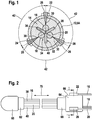
- the representation according to FIG. 1 is a section through a (executed in this example as insulation displacement connector) plug to remove, which comprises an electrode assembly for an electrochemical sensor.
- FIG. 1 illustrated cross section through an electrochemical sensor 10 shows an electrode assembly 16, 18, 20.
- the electrode assembly 16, 18, 20 is enclosed by a jacket 12, which can enclose an embedding material 14.
- the electrode arrangement comprises at least one working electrode 16, at least one counterelectrode 18 and at least one reference electrode 20.
- the electrode arrangement 16, 18, 20 extends in the illustration according to FIG FIG. 1 perpendicular to the plane of the drawing, wherein the at least one working electrode 16, the at least one counter electrode 18 and the at least one reference electrode 20 parallel to each other.
- the at least one working electrode 16, the at least one counter electrode 18 and the at least one reference electrode 20 form an electrochemical measuring cell and at the same time the body of the electrochemical sensor 10.
- the at least one working electrode 16 is made of a material suitable for electrochemical purposes, such as gold, silver , Palladium, platinum or carbon. The use of other precious metals or other metals or metal alloys, even in multi-layer arrangement, is conceivable.
- the at least one working electrode 16 is coated to detect the analyte with a suitable reagent as described in more detail below.
- the at least one counter-electrode 18 is also made of a suitable material for electrochemical purposes, such as gold, silver, palladium, platinum or carbon, and can remain uncoated or even coated one or more layers. Again, as an alternative or in addition, as with the other electrodes, it is also possible to use further metals (preferably noble metals) or metal alloys or multilayer metals.
- the at least one reference electrode 20 is preferably made of a silver wire, which on its lateral surface with silver chloride is occupied. The at least one reference electrode 20 is used for the currentless measurement of the potential of the at least one working electrode.
- connection 22 for producing an electrical contact of the at least one working electrode 16 a terminal 24 for electrically contacting the at least one counter electrode 18 and an electrical connection 26 for making electrical contact at least one reference electrode 20 are formed.
- a connection 22 for producing an electrical contact of the at least one working electrode 16 a terminal 24 for electrically contacting the at least one counter electrode 18 and an electrical connection 26 for making electrical contact at least one reference electrode 20 are formed.
- the number of electrodes 16, 18, 20 corresponding number of terminals 22, 24, 26 arranged in a circumferential pitch 42, which is 120 ° in the illustrated schematically illustrated embodiment.
- a corresponding number of terminals 22, 24, 26 is provided on the jacket 12 of the electrochemical sensor 10.
- the contacting elements 28 may be formed as cutting clamps, which include a cutting edge 30.
- the ends of the wires can also be exposed and separated onto one Terminal board soldered, bonded or glued. Subsequently, this arrangement can be cast, for example, in a connector housing, for example.
- the at least one working electrode 16, the at least one counterelectrode 18 and the at least one reference electrode 20 are insulated from each other by an insulating profile 32.
- the insulation profile 32 is formed in Y-geometry, which results in each case a receiving compartment, the at least one working electrode 16, the at least one counter electrode 18 and the at least one reference electrode 20 receives results.
- the insulation profile 32 is manufactured as a strand extrusion profile.
- the insulation profile 32 may also have a different configuration, such as X-shaped or T-shaped. A cross-shaped design of the geometry of the insulation profile 32 is possible.
- the geometry 34 of the insulation profile ensures that the at least one working electrode 16, the at least one counter electrode 18 and the at least one reference electrode 20, which run parallel to each other, are separated from each other by the insulation profile, for example by the insulation profile 32, by webs.
- sectional insulation profile 32 shown in Y-geometry 34 includes a first web 36 which separates the at least one counter electrode 18 from the at least one working electrode 16.
- a second web 38 of the insulation profile 32 is used to separate the at least one working electrode 16 from the at least one reference electrode 20, which in turn is separated from the at least one counterelectrode 18 of the electrode arrangement 16, 18, 20 by a third web 40 of the insulation profile 32.
- the schematic representation according to FIG. 2 It can be seen that the electrochemical sensor 10 is part of a device having an insertion head 60.
- the insertion head 60 is rounded at its end and has a diameter of preferably ⁇ 1 mm, in particular ⁇ 500 microns and particularly preferably ⁇ 50 microns.
- the insertion head 60 is used for subcutaneous insertion of the electrochemical sensor into a body tissue.
- the insertion head 60 is sealed off from the electrode arrangement 16, 18, 20 via a first seal 32, wherein in the illustration according to FIG FIG. 2 only the at least one working electrode 16 and the at least one reference electrode 20 are shown.
- the double arrow indicated by reference numeral 70 indicates the direction of movement in the device for determining an analyte concentration in a body tissue or in a body fluid.
- the electrochemical sensor 10 can be introduced into the tissue via a slotted hollow needle, wherein instead of an insertion head 60, only an insulation of the end face of the sensor 10 can be used.
- the electrochemical sensor 10 can also be pulled under the skin by means of an insertion aid, for example a needle or a blade.
- an insertion aid for example a needle or a blade.
- a form-fitting part can be used, which serves as a driver and when pulling out the introducer does not retract the electrochemical sensor 10 again.
- the electrochemical sensor 10 itself should be designed in such a way that, after the end of its use, it can also be removed from the tissue relatively easily.
- connection carrier 64 In addition to the insertion head 60 and the electrode arrangement 16, 18, 20, a device shown in FIG. 1 shown in cross-section connection carrier 64, the, as above in connection with FIG. 1 described, preferably designed as insulation displacement connector.
- the connection carrier 64 ensures the electrical contacting of the at least one working electrode 16, the at least one counterelectrode 18 and the at least one reference electrode 20.
- the connection carrier 64 has a circumference 66 at which the in FIG. 1 terminals 22, 24, 26 shown for electrically contacting the at least one working electrode 16, the at least one counter electrode 18 and the at least one reference electrode 20 are electrically contacted. As related to FIG.
- the electrical contacting elements 28 are preferably designed as cutting edges 30 wedge-shaped elements, each of which contact the peripheral surface of the at least one working electrode 16, the at least one counter electrode 18 and the at least one reference electrode 20 electrical.
- an evaluation unit which evaluates the signals that are transmitted via the at least one working electrode 16 and the at least one counterelectrode 18, evaluates and makes a determination of the analyte concentration in the body tissue or in a body fluid and directly displays it to the user.
- connection support 64 which can preferably be designed as a form-fitting part
- the electrode arrangement 16, 18, 20 comprising a reference electrode 20
- different lengths of the electrode assembly 16, 18, 20 between the first seal 62 to the insertion head 60 and the second seal 68 to the connection carrier 64 can be realized.
- the at least one working electrode 16, the at least one working electrode 18 and the at least one reference electrode 20 the electrochemical measuring cell, which is enclosed after insertion of the insertion head 60 from the body tissue and allows detection of an analyte in a body tissue or a body fluid. Due to the design of the at least one working electrode 16, the at least one counter-electrode 18 and the at least one reference electrode 20 as wire-shaped components, the electrode arrangement 16, 18, 20 has a very elongated surface.
- the electrochemical detection occurs in a large area of tissue.
- local inhomogeneities eg, insulating fat cells
- High power conversion is also typically associated with high glucose consumption. This can lead to depletion of tissue and thus to erroneously as too low measured values.
- the aim is therefore not to choose the electrode surface, but at the same time to capture a lot of space in the tissue. This goal is achieved in particular by long, thin wires.
- the glucose consumption can also be throttled by a thicker immobilization layer. The thinner electrode package is executed, the lower are usually disturbing interactions with the body tissue (eg cell growth or wound healing).
- the representation according to FIG. 3 is a first manufacturing step of the electrode configuration as in FIGS Figures 1 and 2 shown by an electrochemical sensor, refer to.
- the inventively proposed electrochemical sensor 10 is characterized by a manufacturing process, which allows the use of advantageous for large-scale production individual production steps.
- the components of the electrochemical sensor 10 are substantially the at least one working electrode 16, the at least one counter electrode 18 and the at least one reference electrode 20 and the insulating profile 32.
- the for producing a single or multi-layer coating of the at least one working electrode 16, the at least one counter electrode 18 and the at least one reference electrode 20 will be described in more detail below.
- the at least one working electrode 16 of the electrode assembly 16, 18, 20 is coated with a suitable reagent for detecting that analyte in a body tissue to be determined.
- This coating step is performed as shown in FIG. 3 made in the context of an annular nozzle coating 82.
- the at least one working electrode 16 moves in the conveying direction 80 through an annular nozzle 84.
- the annular nozzle 84 comprises a cavity 92 which is filled with a reagent medium 86.
- the promotion of the reagent medium 86 in the cavity 92 of the annular nozzle 84 is effected by a feed pump 90.
- the reagent medium 86 may be, for example, a mixture of manganese dioxide (manganese dioxide), graphite and GOD (glucose oxidase), which catalytically convert glucose to gluconolactone.
- the film of the reagent medium 86 is dried on the surface 94 of the at least one working electrode 16, followed by the manufacturing steps described below.
- FIG. 4 shows the merging of the at least one coated working electrode with the at least one counter electrode, the at least one reference electrode and the present in strand form isolation profile.
- At least one working electrode 16 coated with a reagent medium 86 is supplied to a merging station 130 as at least one coated working electrode 110. Further, the merging station 130, the at least one, preferably uncoated counter electrode 18 and the at least one reference electrode 20 are supplied. Furthermore, the merging station 130 is supplied with the insulation profile 32, which is preferably produced as a strand extrusion profile, which has the insulation profile Figure 4.1 shown Y-geometry 34 has.
- the at least now coated working electrode 16, the at least one, for example uncoated or coated, counter electrode 18 and the at least one reference electrode 20 are grouped around the insulation profile 32 that the at least one working electrode 16, the at least one counter electrode 18 and the at least one reference electrode 20 are isolated from each other.
- the merging station 130 leaves an electrode arrangement, the at least one coated working electrode 16, at least one, preferably uncoated counter electrode 18, at least one reference electrode 20 and includes the isolation profile 32.
- the electrode assembly 16, 18, 20 leaving the merging station 130 constitutes an electrode package 132.
- the representation according to FIG. 5 is another manufacturing step, which the electrode package according to FIG. 4 is supplied after the merger, refer to.
- FIG. 5 2 shows that the electrode package 132, which comprises the at least one coated working electrode 110 which comprises at least one preferably uncoated counterelectrode 18 and the at least one reference electrode 20, is supplied to an immobilization medium coating 140.
- an immobilization medium 142 shown in FIG. 5 applied in an annular nozzle 146 incoming electrode package 132.
- the electrode packet is additionally isolated and / or toxic components (for example the GOD acting as a cytotoxin) are prevented from diffusing into the body tissue.
- the outside of the electrochemical sensor 10, which comes in contact with the body tissue, should be biocompatible (ie not repelled by the body). This is another particularly preferred property of the immobilization medium 142. Alternatively or additionally, an additional layer can be applied, which ensures this additional property of biocompatibility.
- the other materials used, which come into contact with the body tissue, for example, materials for insulation in the connector area and at the insertion end, should have corresponding biocompatible properties or coated accordingly.
- the annular nozzle 146 used in the context of the immobilization medium coating 140 comprises a cavity 150, which has an outlet opening 148 and is filled with an immobilization medium 142.
- the cavity 150 of the annular nozzle 146 is filled continuously with the immobilization medium 142, so that the entire surface of the electrode package 132 entering the cavity in the conveying direction 80 is wetted by the immobilization medium 142.
- the lateral surface of the electrode packet 132 which enters the annular nozzle 146 in the conveying direction 80, is provided with a coating with immobilization medium 142.
- the conveying direction of the electrode package 132 is shown in FIG FIG. 5 designated by reference numeral 144.
- Reference numeral 152 denotes the electrode package 132 coated with the immobilization medium 142.
- the annular nozzle 146 in the conveying direction 144 entering electrode package 132 which comprises the at least one working electrode 16, the at least one counter electrode 18 and the at least one reference electrode 20, which are insulated from each other by the insulating profile 32, and individual of the at least one working electrode 16, the At least one counter electrode 18 and the at least one reference electrode 20 of the immobilization medium coating 140 are supplied.
- the immobilization medium coating 140 which according to FIG. 5 can be applied, the contact between the at least one coated working electrode 110 and the at least one, preferably uncoated counter electrode 18 and the body tissue or the body fluid, whereby the presence of a particular analyte is to be determined.
- the representation according to FIG. 6 is a confectioning step removable.
- coated electrode package 152 which is coated on the periphery, for example, with the immobilization medium 142, assembled into individual sections 164.
- the assembly 160 is preferably carried out by a transverse cutting of the coated electrode package 152. In this case, different lengths 162 of the assembled sections 164 can be adjusted depending on the application.
- FIG. 2 not shown in full length device comprising an electrochemical sensor 10 obtained.
- the electrochemical measuring cell of the electrochemical sensor 10 is formed by the lateral surface of the layer of immobilization medium 142 applied as part of the immobilization medium coating 140. This layer of immobilization medium 142 represents the boundary of the electrochemical measuring cell and the contact surface with which the electrochemical sensor 10 is in contact with the body tissue or body fluid.
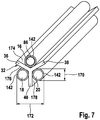
- the representation according to FIG. 7 is a perspective view of the electrode assembly of the electrochemical sensor 10 can be seen.
- FIG. 7 shows that the at least one working electrode 16, the at least one counter electrode 18 and the at least one reference electrode 20 are separated from each other via the insulating profile 32.
- an insulating profile 32 having Y-geometry 34 comprises the first web 36, the second web 38 and the third web 40.
- the first web 36 and the second web 38 delimit a first receiving compartment 174 in which the at least one working electrode 16 is accommodated.
- the at least one working electrode 16 has a coating with a reagent medium 86 of a reagent for detecting the analyte in the body tissue or in the body fluid. From the illustration according to FIG. 7 It can be seen that the immobilization medium 142 can be applied to this reagent medium 86.
- FIG. 7 illustrated embodiment of the electrode assembly 16, 18, 20 of the electrode assembly 132 is the Immobilleitersmedium 142 on the lateral surface of the at least one working electrode 16, the at least one counter electrode 18 and the at least one reference electrode 20 applied.
- FIG. 5 also described the entire from the merge station 130 according to FIG. 4 emerging electrode package 132 are coated as a whole with the Immobilticiansmedium 142, which then the in FIG. 1 illustrated embedding material 14 represents.
- FIG. 7 The perspective view according to FIG. 7 Furthermore, it can be seen that the second web 38 with the third web 40 of the insulating profile 42 defines a third receiving compartment 178, in which in the exemplary embodiment according to FIG. 7 the at least one reference electrode 20 is received. Finally, the third land 40 and the first land 36 define the insulation profile 32 as shown in FIG FIG. 7 a second receiving compartment 176, in which the at least one counter electrode 18 of the electrode assembly 16, 18, 20 is located. From the illustration according to FIG.
- a diameter 170 of the reference electrode is on the order of about 100 .mu.m
- reference numeral 172 denotes the sum of the diameters of the at least one reference electrode 20, the at least one counter electrode 18 and the material thickness of the third web 40 of the insulation profile 32.
- the route 172 as shown in FIG. 7 has a length of the order of about 250 microns.
- the proposed electrode assembly 16, 18, 20 of the present invention proposed electrochemical sensor 10 has very compact dimensions, which is due to the parallel arrangement of at least one Working electrode 16, the at least one counter electrode 18 and the at least one reference electrode 20 in the receiving compartments 174, 176 and 178 of the insulation profile 32 is based.
- the representation according to FIG. 8 is a schematic representation of the manufacturing process for producing the electrochemical sensor, in particular the electrode assembly can be seen.
- the at least one working electrode 16 is coated with the reagent medium 86, which is a suitable reagent for detecting the analyte.
- the reagent medium 86 which is located after the annular nozzle coating 82 on the surface 94 of the at least one working electrode 16, dried.
- the electrode package 132 obtained from the merge station 130 is subsequently subjected to an immobilization medium coating 140.
- an immobilization medium coating 140 it is possible to apply the immobilization medium 142 both to the electrode package 132 obtained in the merging station 130 as a whole and consequently to embed it in the immobilization medium.
- a separation takes place either of the coated electrode package 152 or of the combined individually coated individual electrodes 16, 18 and 20.
- sections 164 are produced which are formed in different lengths 162 can be, with the length 162 depends on the application of the electrode assembly for use in an electrochemical sensor 10.
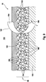
- FIG. 9 schematically a section of an electrode surface of a working electrode 16 is shown in sectional view.
- the working electrode has a gold wire 180 in this example.
- the gold wire 180 is according to the in FIG. 8 Process described coated with a reagent medium 86.
- the reagent medium in this example consists of three different components: conductive carbon particles 182, brownstone particles 184, GOD particles or GOD conglomerates 186 and a binder polymer 188.
- the binder polymer 188 ensures the processing properties of the reagent medium in undried condition.
- the reagent medium 86 is adjusted by selecting the binder polymer 188 in its viscosity and / or surface tension so that it can be processed well in the "wet" (ie undried) state by annular die coating 82 and a homogeneous, uniform, good on the gold wire Forms 180 adherent layer.
- the binder polymer is selected such that it can be dried at moderate temperatures without, for example, thermally destroying GOD 186 in this drying step.
- suitable binder polymer 188 include mixtures, for example mixtures of polymers with various solvents.
- FIG. 9 also the layer of Immobilticiansmediums 142 shown. This surrounds the reagent medium 86 and prevents body fluid (symbolically denoted here by 190) from coming into direct contact with the brownstone particles 184 and with the GOD particles 186 and that GOD can diffuse into the body fluid 190. At the same time, oxygen and glucose as analyte to be detected can diffuse out of the body fluid 190 through the layer of the immobilization medium 142 and thus reach the reagent medium 86.
- body fluid symbolically denoted here by 190
- FIG. 9 symbolically represents the reaction used to detect glucose 194 in body fluid 190 by a "reaction arrow" 192.
- Glucose 194 is oxidized to gluconolactone via the enzyme GOD 186 and subsequently oxygen is reduced to H 2 O 2 by the enzyme GOD 186.
- the H 2 O 2 is catalytically oxidized by the manganese dioxide 184 and thereby the electrons are transferred to the dissipative gold wire 180 via the carbon particles 182 which are in contact with the manganese dioxide 184.
- the potential of the gold wire 180 (or the entire working electrode 16) influenced in this way can be detected in the manner described above, for example by an amperometric measurement, and the concentration of glucose in the body fluid 190 can be deduced therefrom.
Landscapes
- Health & Medical Sciences (AREA)
- Life Sciences & Earth Sciences (AREA)
- Physics & Mathematics (AREA)
- Chemical & Material Sciences (AREA)
- Engineering & Computer Science (AREA)
- Molecular Biology (AREA)
- General Health & Medical Sciences (AREA)
- Pathology (AREA)
- Biomedical Technology (AREA)
- Biophysics (AREA)
- Chemical Kinetics & Catalysis (AREA)
- Electrochemistry (AREA)
- Analytical Chemistry (AREA)
- Biochemistry (AREA)
- General Physics & Mathematics (AREA)
- Immunology (AREA)
- Optics & Photonics (AREA)
- Medical Informatics (AREA)
- Heart & Thoracic Surgery (AREA)
- Surgery (AREA)
- Animal Behavior & Ethology (AREA)
- Public Health (AREA)
- Veterinary Medicine (AREA)
- Hematology (AREA)
- Emergency Medicine (AREA)
- Organic Chemistry (AREA)
- Metallurgy (AREA)
- Materials Engineering (AREA)
- Manufacturing & Machinery (AREA)
- Urology & Nephrology (AREA)
- Food Science & Technology (AREA)
- Medicinal Chemistry (AREA)
- Measurement Of The Respiration, Hearing Ability, Form, And Blood Characteristics Of Living Organisms (AREA)
- Investigating Or Analysing Materials By The Use Of Chemical Reactions (AREA)
- Secondary Cells (AREA)
Claims (13)
- Capteur électrochimique (10) destiné à la détermination d'une concentration d'au moins un analyte dans un milieu, en particulier dans un tissu corporel et/ou un fluide corporel, dans lequel le capteur électrochimique (10) comporte un élément isolant (32) et au moins deux électrodes (16, 18, 20), dans lequel les au moins deux électrodes (16, 18, 20) comprennent au moins une électrode de travail (16) et au moins une électrode supplémentaire (18, 20), en particulier au moins une contre-électrode (18) et/ou au moins une électrode de référence (20), dans lequel les au moins deux électrodes (16, 18, 20) sont réalisées au moins partiellement comme électrodes en forme de câbles essentiellement parallèles dotées de surfaces d'électrodes situées sur leur circonférence, dans lequel les au moins deux électrodes (16, 18, 20) s'étendent le long d'un élément isolant (32) réalisé en forme de profilé, caractérisé en ce que l'élément isolant (32) réalisé en forme profilée comporte au moins deux réceptacles (174, 176, 178) pour les au moins deux électrodes (16, 18, 20), et en ce que l'au moins une électrode de travail (16) est enveloppée au moins en partie, de préférence totalement, par un milieu réactif (86) pour la détermination d'une concentration d'au moins un analyte dans un milieu, en particulier dans un tissu corporel et/ou un fluide corporel.
- Capteur électrochimique selon la revendication 1, caractérisé en ce que les au moins deux électrodes (16, 18, 20) sont enveloppées entièrement ou partiellement par au moins une couche d'un milieu d'immobilisation (142), individuellement ou sous forme d'un paquet d'électrodes (132) .
- Capteur électrochimique selon la revendication 2, caractérisé en ce que le milieu d'immobilisation (142) présente une perméabilité au moins partielle pour l'au moins un analyte.
- Capteur électrochimique selon la revendication 2 ou 3, caractérisé en ce que le milieu d'immobilisation (142) comporte un polyuréthane et/ou un matériau polymère supplémentaire.
- Capteur électrochimique selon la revendication 1, caractérisé en ce que le profil isolant (32) est fabriqué en polymère, en particulier en polymère électriquement isolant.
- Capteur électrochimique selon l'une des revendications précédentes, caractérisé en ce que- l'au moins une électrode de travail (16) comprend au moins un matériau d'électrode adapté pour une réaction de transfert électronique et pour un transport de courant, de préférence des particules de graphite sur or, lequel comprend au moins un matériau issu du groupe comprenant l'or, l'argent, le palladium, le platine ou le carbone, et- en ce que le matériau d'électrode est enveloppé par au moins un milieu réactif (86), lequel comporte au moins un matériau issu du groupe comprenant : un catalyseur électro-redox pour réduire la surtension, en particulier le MnO2 (dioxyde de manganèse) ; un médiateur ; une enzyme comme catalyseur spécifique d'un analyte à détecter, en particulier la glucose oxydase (GOD) ; du carbone ; un matériau polymère liant,- dans lequel l'au moins un milieu réactif (86) est entouré de préférence au moins partiellement, en particulier totalement, par un milieu d'immobilisation (142).
- Capteur électrochimique selon l'une des revendications précédentes, caractérisé en ce qu'au moins une contre-électrode (18) est prévue, dans lequel l'au moins une contre-électrode (18) est fabriquée à partir d'un matériau adapté aux mesures électrochimiques issu du groupe comprenant l'or, l'argent, le palladium, le platine ou le carbone.
- Capteur électrochimique selon l'une des revendications précédentes, caractérisé en ce qu'au moins une électrode de référence est prévue, dans lequel l'au moins une électrode de référence (20) comporte de préférence de l'argent Ag et est couverte de chlorure d'argent AgCl sur sa surface et est enveloppée au moins partiellement, en particulier totalement, par un milieu d'immobilisation (142).
- Dispositif (10, 60, 64) destiné à la détermination d'une concentration d'au moins un analyte dans un milieu, en particulier dans un tissu corporel et/ou un fluide corporel, doté d'au moins un capteur électrochimique (10) selon l'une des revendications précédentes, doté d'au moins un dispositif de mesure de tension et/ou au moins un dispositif de mesure d'intensité destiné à la mesure d'une tension et/ou d'une intensité entre l'au moins une électrode de travail (16) et l'au moins une contre-électrode (18) et/ou l'au moins une électrode de référence, ainsi que doté en outre, de préférence, d'une tête d'insertion (60) et/ou d'une aide d'insertion.
- Dispositif selon la revendication 9, caractérisé en ce que le capteur électrochimique (10) est connecté à un raccord électrique (64), de préférence à un raccord électrique (64) réalisé comme pièce à complémentarité de formes.
- Dispositif selon la revendication 10, caractérisé en ce que le raccord électrique (64) comporte au moins deux raccords électriques (22, 24, 26) pour les au moins deux électrodes (16, 18, 20) afin de créer un contact électrique avec les surfaces de celles-ci.
- Dispositif selon la revendication 10, caractérisé en ce que le raccord électrique comporte une connexion autodénudante et/ou une aide d'insertion et/ou une aiguille creuse.
- Utilisation d'un dispositif (10, 60, 64) selon l'une des revendications précédentes concernant un dispositif (10, 60, 64) pour une détermination continue d'une concentration d'au moins un analyte dans un milieu, en particulier dans un tissu corporel et/ou un fluide corporel.
Priority Applications (5)
| Application Number | Priority Date | Filing Date | Title |
|---|---|---|---|
| EP17189211.0A EP3282250B1 (fr) | 2006-08-08 | 2007-08-03 | Capteur électrochimique destiné à la détermination d'une concentration analytique |
| DK17189211.0T DK3282250T3 (da) | 2006-08-08 | 2007-08-03 | Elektrokemisk sensor til bestemmelse af en analytkoncentration |
| SI200732138T SI2302376T1 (sl) | 2006-08-08 | 2007-08-03 | Elektrokemični senzor za določanje koncentracije analita |
| PL17189211T PL3282250T3 (pl) | 2006-08-08 | 2007-08-03 | Czujnik elektrochemiczny do określania stężenia analitu |
| PL10197027T PL2302376T3 (pl) | 2006-08-08 | 2007-08-03 | Czujnik elektrochemiczny do określania stężenia analitu |
Applications Claiming Priority (4)
| Application Number | Priority Date | Filing Date | Title |
|---|---|---|---|
| DE102006037328 | 2006-08-08 | ||
| EP06123227A EP1918706A1 (fr) | 2006-10-31 | 2006-10-31 | Capteur électrochimique destiné à la détermination d'une concentration analytique |
| EP07788207A EP2049895B1 (fr) | 2006-08-08 | 2007-08-03 | Capteur electrochimique pour determiner une concentration d'analyte |
| PCT/EP2007/058074 WO2008017645A1 (fr) | 2006-08-08 | 2007-08-03 | Capteur électrochimique pour déterminer une concentration d'analyte |
Related Parent Applications (2)
| Application Number | Title | Priority Date | Filing Date |
|---|---|---|---|
| EP07788207.4 Division | 2007-08-03 | ||
| EP07788207A Division EP2049895B1 (fr) | 2006-08-08 | 2007-08-03 | Capteur electrochimique pour determiner une concentration d'analyte |
Related Child Applications (2)
| Application Number | Title | Priority Date | Filing Date |
|---|---|---|---|
| EP17189211.0A Division EP3282250B1 (fr) | 2006-08-08 | 2007-08-03 | Capteur électrochimique destiné à la détermination d'une concentration analytique |
| EP17189211.0A Division-Into EP3282250B1 (fr) | 2006-08-08 | 2007-08-03 | Capteur électrochimique destiné à la détermination d'une concentration analytique |
Publications (2)
| Publication Number | Publication Date |
|---|---|
| EP2302376A1 EP2302376A1 (fr) | 2011-03-30 |
| EP2302376B1 true EP2302376B1 (fr) | 2019-10-02 |
Family
ID=38481535
Family Applications (3)
| Application Number | Title | Priority Date | Filing Date |
|---|---|---|---|
| EP10197027.5A Active EP2302376B1 (fr) | 2006-08-08 | 2007-08-03 | Capteur électrochimique destiné à la détermination d'une concentration analytique |
| EP17189211.0A Active EP3282250B1 (fr) | 2006-08-08 | 2007-08-03 | Capteur électrochimique destiné à la détermination d'une concentration analytique |
| EP07788207A Active EP2049895B1 (fr) | 2006-08-08 | 2007-08-03 | Capteur electrochimique pour determiner une concentration d'analyte |
Family Applications After (2)
| Application Number | Title | Priority Date | Filing Date |
|---|---|---|---|
| EP17189211.0A Active EP3282250B1 (fr) | 2006-08-08 | 2007-08-03 | Capteur électrochimique destiné à la détermination d'une concentration analytique |
| EP07788207A Active EP2049895B1 (fr) | 2006-08-08 | 2007-08-03 | Capteur electrochimique pour determiner une concentration d'analyte |
Country Status (9)
| Country | Link |
|---|---|
| US (3) | US8828200B2 (fr) |
| EP (3) | EP2302376B1 (fr) |
| AT (1) | ATE493645T1 (fr) |
| DE (1) | DE502007006125D1 (fr) |
| DK (2) | DK3282250T3 (fr) |
| ES (2) | ES2758834T3 (fr) |
| PL (2) | PL2302376T3 (fr) |
| SI (2) | SI3282250T1 (fr) |
| WO (1) | WO2008017645A1 (fr) |
Families Citing this family (18)
| Publication number | Priority date | Publication date | Assignee | Title |
|---|---|---|---|---|
| WO2009032760A2 (fr) | 2007-08-30 | 2009-03-12 | Pepex Biomedical Llc | Capteur électrochimique et procédé de fabrication |
| WO2009051901A2 (fr) | 2007-08-30 | 2009-04-23 | Pepex Biomedical, Llc | Capteur électrochimique et procédé de fabrication |
| WO2010056876A2 (fr) | 2008-11-14 | 2010-05-20 | Pepex Biomedical, Llc | Fabrication d’un module de capteurs électrochimiques |
| US8951377B2 (en) | 2008-11-14 | 2015-02-10 | Pepex Biomedical, Inc. | Manufacturing electrochemical sensor module |
| US9445755B2 (en) | 2008-11-14 | 2016-09-20 | Pepex Biomedical, Llc | Electrochemical sensor module |
| FI20095232A0 (fi) * | 2009-03-09 | 2009-03-09 | Oulun Yliopisto | Hiilikuitumonikanavaelektrodi sähköisen ja kemiallisen aktiviteetin mittaamiseksi biologisessa kudoksessa ja prosessi elektrodin valmistamiseksi |
| JP5463788B2 (ja) * | 2009-08-18 | 2014-04-09 | 富士通株式会社 | イオン分析装置、及びイオン分析方法 |
| US10448872B2 (en) * | 2010-03-16 | 2019-10-22 | Medtronic Minimed, Inc. | Analyte sensor apparatuses having improved electrode configurations and methods for making and using them |
| WO2012149410A2 (fr) * | 2011-04-29 | 2012-11-01 | Abbott Diabetes Care Inc. | Procédés de collecte et d'analyse d'échantillons |
| WO2012162151A2 (fr) | 2011-05-20 | 2012-11-29 | Pepex Biomedical, Inc. | Fabrication de modules de détection électrochimique |
| JP6110871B2 (ja) * | 2011-12-02 | 2017-04-05 | コーニンクレッカ フィリップス エヌ ヴェKoninklijke Philips N.V. | 溶液のpH値を検出するための方法及び装置 |
| WO2014089058A1 (fr) | 2012-12-03 | 2014-06-12 | Pepex Biomedical, Inc. | Module de capteur et procédé d'utilisation d'un module de capteur |
| US9999856B2 (en) * | 2013-07-26 | 2018-06-19 | General Electric Company | Methods for electroelution of biomolecules |
| US11045124B2 (en) | 2014-06-04 | 2021-06-29 | Pepex Biomedical, Inc. | Electrochemical sensors and methods for making electrochemical sensors using advanced printing technology |
| US11998319B2 (en) | 2015-03-09 | 2024-06-04 | CoreSyte, Inc. | Device for measuring biological fluids |
| US11883011B2 (en) * | 2015-03-09 | 2024-01-30 | CoreSyte, Inc. | Method for manufacturing a biological fluid sensor |
| EP3263712A1 (fr) | 2016-06-29 | 2018-01-03 | Roche Diabetes Care GmbH | Capteurs fonctionnalisées par voie galvanique |
| CN110865109A (zh) * | 2019-12-25 | 2020-03-06 | 广州商辉仪业智能科技股份有限公司 | 一种参比电极隔离适配器 |
Family Cites Families (21)
| Publication number | Priority date | Publication date | Assignee | Title |
|---|---|---|---|---|
| DE7442096U (de) * | 1974-12-18 | 1977-02-24 | Felten & Guilleaume Kabelwerke Ag, 5000 Koeln | Elektrische Leitung |
| US4671288A (en) * | 1985-06-13 | 1987-06-09 | The Regents Of The University Of California | Electrochemical cell sensor for continuous short-term use in tissues and blood |
| US4805624A (en) | 1985-09-09 | 1989-02-21 | The Montefiore Hospital Association Of Western Pa | Low-potential electrochemical redox sensors |
| DK115989D0 (da) | 1989-03-09 | 1989-03-09 | Nordisk Gentofte | Fremgangsmaade og middel til maaling af en vaeskekomponent |
| US5985129A (en) * | 1989-12-14 | 1999-11-16 | The Regents Of The University Of California | Method for increasing the service life of an implantable sensor |
| US5286362A (en) | 1990-02-03 | 1994-02-15 | Boehringer Mannheim Gmbh | Method and sensor electrode system for the electrochemical determination of an analyte or an oxidoreductase as well as the use of suitable compounds therefor |
| CA2050677C (fr) | 1990-09-06 | 2003-04-08 | Ernest J. Kiser | Methode de mesure visuelle de la glycemie |
| DE4105222A1 (de) * | 1991-02-20 | 1992-08-27 | Schaefer Wieland Dr Sc | Einstabmikromesskette |
| US5591139A (en) | 1994-06-06 | 1997-01-07 | The Regents Of The University Of California | IC-processed microneedles |
| DE4422068A1 (de) | 1994-06-23 | 1996-01-04 | Siemens Ag | Elektrokatalytischer Glucosesensor |
| US6004818A (en) * | 1997-08-07 | 1999-12-21 | Chrono-Log Corporation | Aggregometer with disposable test cell |
| US5984711A (en) * | 1998-09-10 | 1999-11-16 | Scimed Life Systems, Inc. | Methods and apparatus for increasing wire diameter to improve connectability |
| US6360888B1 (en) | 1999-02-25 | 2002-03-26 | Minimed Inc. | Glucose sensor package system |
| DE20009392U1 (de) * | 2000-05-25 | 2000-11-16 | Ratzesberger, Konrad, 94544 Hofkirchen | Zuckermeßgerät als Ohrclips |
| US6576102B1 (en) * | 2001-03-23 | 2003-06-10 | Virotek, L.L.C. | Electrochemical sensor and method thereof |
| US20020179457A1 (en) * | 2001-05-18 | 2002-12-05 | Adam Heller | Electrochemical method for high-throughput screening of minute quantities of candidate compounds |
| US7153265B2 (en) * | 2002-04-22 | 2006-12-26 | Medtronic Minimed, Inc. | Anti-inflammatory biosensor for reduced biofouling and enhanced sensor performance |
| US7424318B2 (en) * | 2003-12-05 | 2008-09-09 | Dexcom, Inc. | Dual electrode system for a continuous analyte sensor |
| EP2239566B1 (fr) * | 2003-12-05 | 2014-04-23 | DexCom, Inc. | Techniques d'étalonnage pour capteur d'analytes en continu |
| CN100367906C (zh) * | 2004-12-08 | 2008-02-13 | 圣美迪诺医疗科技(湖州)有限公司 | 皮下植入式生物传感器 |
| US8133178B2 (en) * | 2006-02-22 | 2012-03-13 | Dexcom, Inc. | Analyte sensor |
-
2007
- 2007-08-03 AT AT07788207T patent/ATE493645T1/de active
- 2007-08-03 SI SI200732155T patent/SI3282250T1/sl unknown
- 2007-08-03 ES ES10197027T patent/ES2758834T3/es active Active
- 2007-08-03 EP EP10197027.5A patent/EP2302376B1/fr active Active
- 2007-08-03 PL PL10197027T patent/PL2302376T3/pl unknown
- 2007-08-03 EP EP17189211.0A patent/EP3282250B1/fr active Active
- 2007-08-03 EP EP07788207A patent/EP2049895B1/fr active Active
- 2007-08-03 PL PL17189211T patent/PL3282250T3/pl unknown
- 2007-08-03 WO PCT/EP2007/058074 patent/WO2008017645A1/fr active Application Filing
- 2007-08-03 DK DK17189211.0T patent/DK3282250T3/da active
- 2007-08-03 SI SI200732138T patent/SI2302376T1/sl unknown
- 2007-08-03 ES ES17189211T patent/ES2797125T3/es active Active
- 2007-08-03 DK DK10197027T patent/DK2302376T3/da active
- 2007-08-03 DE DE502007006125T patent/DE502007006125D1/de active Active
-
2009
- 2009-02-09 US US12/367,725 patent/US8828200B2/en active Active
-
2014
- 2014-08-06 US US14/452,825 patent/US9255903B2/en active Active
-
2016
- 2016-02-02 US US15/013,094 patent/US10060877B2/en active Active
Non-Patent Citations (1)
| Title |
|---|
| None * |
Also Published As
| Publication number | Publication date |
|---|---|
| US8828200B2 (en) | 2014-09-09 |
| EP2049895A1 (fr) | 2009-04-22 |
| US20140345130A1 (en) | 2014-11-27 |
| DK2302376T3 (da) | 2019-12-09 |
| DE502007006125D1 (de) | 2011-02-10 |
| EP3282250B1 (fr) | 2020-04-08 |
| PL2302376T3 (pl) | 2020-03-31 |
| ES2797125T3 (es) | 2020-12-01 |
| EP2049895B1 (fr) | 2010-12-29 |
| WO2008017645A1 (fr) | 2008-02-14 |
| EP2302376A1 (fr) | 2011-03-30 |
| ES2758834T8 (es) | 2020-05-14 |
| PL3282250T3 (pl) | 2020-08-24 |
| EP3282250A1 (fr) | 2018-02-14 |
| ATE493645T1 (de) | 2011-01-15 |
| US20160153933A1 (en) | 2016-06-02 |
| US20090178923A1 (en) | 2009-07-16 |
| DK3282250T3 (da) | 2020-06-15 |
| US9255903B2 (en) | 2016-02-09 |
| ES2758834T3 (es) | 2020-05-06 |
| US10060877B2 (en) | 2018-08-28 |
| SI3282250T1 (sl) | 2020-07-31 |
| SI2302376T1 (sl) | 2019-12-31 |
Similar Documents
| Publication | Publication Date | Title |
|---|---|---|
| EP2302376B1 (fr) | Capteur électrochimique destiné à la détermination d'une concentration analytique | |
| EP1962668B1 (fr) | Capteur en sandwich destine a determiner une concentration d'analyte | |
| EP1987761B1 (fr) | Capteur tubulaire destiné à la détection d'un analyte | |
| DE69132270T2 (de) | Implantierbarer glukose-fühler | |
| DE60020076T2 (de) | Kleinvolumiger in-vitro-analyt-sensor | |
| DE10119036C1 (de) | Tauchsensor zur Messung der Konzentration eines Analyten mit Hilfe einer Oxidase | |
| EP2658444B1 (fr) | Procédé de mise au point d'un biocapteur efficace, ainsi que biocapteur, substrat et kit d'introduction correspondants | |
| DE19621241C2 (de) | Membranelektrode zur Messung der Glucosekonzentration in Flüssigkeiten | |
| DE69809391T2 (de) | Kleinvolumiger sensor zur in-vitro bestimmung | |
| DE60214087T2 (de) | Vorrichtung zur Entnahme biologischer Flüssigkeiten und Analytenmessung | |
| DE2610530C2 (de) | Ionenselektive Meßelektrode | |
| DE69323205T2 (de) | Gasdurchlässige Membranen für amperometrische Gaselektroden und deren Gebrauch | |
| EP1129778A2 (fr) | Système de détermination de la concentration d'un analyte dans des fluides corporels | |
| DE2726450B2 (de) | Katheter-Meßanordnung zur elektrochemischen Analyse | |
| EP1733676A1 (fr) | Système de capteur, disposition et méthode pour surveiller un composé, en particulier le glucose dans le tissu du corps. | |
| EP2544582B1 (fr) | Procédé pour la mesure électrochimique d'une concentration en analyte in vivo et pile à combustible à cet effet | |
| WO2000022977A1 (fr) | Systeme de capteur a invasion minimale | |
| WO2005073705A1 (fr) | Reseau de transducteurs electrochimique et son utilisation | |
| EP1918706A1 (fr) | Capteur électrochimique destiné à la détermination d'une concentration analytique | |
| DE3725597C2 (fr) | ||
| EP1797817A1 (fr) | Capteur de type sandwich pour la détermination de la concentration des analytes | |
| EP0812147A1 (fr) | Systeme de detection implantable pour determiner des concentrations de substances dans des organismes vivants | |
| AT398133B (de) | Ionenselektive elektrodenanordnung | |
| DD282527B5 (de) | Enzymelektrodenanordnung fuer Biosensoren |
Legal Events
| Date | Code | Title | Description |
|---|---|---|---|
| PUAI | Public reference made under article 153(3) epc to a published international application that has entered the european phase |
Free format text: ORIGINAL CODE: 0009012 |
|
| AC | Divisional application: reference to earlier application |
Ref document number: 2049895 Country of ref document: EP Kind code of ref document: P |
|
| AK | Designated contracting states |
Kind code of ref document: A1 Designated state(s): AT BE BG CH CY CZ DE DK EE ES FI FR GB GR HU IE IS IT LI LT LU LV MC MT NL PL PT RO SE SI SK TR |
|
| 17P | Request for examination filed |
Effective date: 20110505 |
|
| 17Q | First examination report despatched |
Effective date: 20110601 |
|
| APBK | Appeal reference recorded |
Free format text: ORIGINAL CODE: EPIDOSNREFNE |
|
| APBN | Date of receipt of notice of appeal recorded |
Free format text: ORIGINAL CODE: EPIDOSNNOA2E |
|
| APBR | Date of receipt of statement of grounds of appeal recorded |
Free format text: ORIGINAL CODE: EPIDOSNNOA3E |
|
| APAF | Appeal reference modified |
Free format text: ORIGINAL CODE: EPIDOSCREFNE |
|
| APAF | Appeal reference modified |
Free format text: ORIGINAL CODE: EPIDOSCREFNE |
|
| RAP1 | Party data changed (applicant data changed or rights of an application transferred) |
Owner name: F. HOFFMANN-LA ROCHE AG Owner name: ROCHE DIABETES CARE GMBH |
|
| APBX | Invitation to file observations in appeal sent |
Free format text: ORIGINAL CODE: EPIDOSNOBA2E |
|
| APBZ | Receipt of observations in appeal recorded |
Free format text: ORIGINAL CODE: EPIDOSNOBA4E |
|
| APAF | Appeal reference modified |
Free format text: ORIGINAL CODE: EPIDOSCREFNE |
|
| APBT | Appeal procedure closed |
Free format text: ORIGINAL CODE: EPIDOSNNOA9E |
|
| STAA | Information on the status of an ep patent application or granted ep patent |
Free format text: STATUS: EXAMINATION IS IN PROGRESS |
|
| GRAP | Despatch of communication of intention to grant a patent |
Free format text: ORIGINAL CODE: EPIDOSNIGR1 |
|
| STAA | Information on the status of an ep patent application or granted ep patent |
Free format text: STATUS: GRANT OF PATENT IS INTENDED |
|
| INTG | Intention to grant announced |
Effective date: 20190503 |
|
| GRAS | Grant fee paid |
Free format text: ORIGINAL CODE: EPIDOSNIGR3 |
|
| GRAA | (expected) grant |
Free format text: ORIGINAL CODE: 0009210 |
|
| STAA | Information on the status of an ep patent application or granted ep patent |
Free format text: STATUS: THE PATENT HAS BEEN GRANTED |
|
| AC | Divisional application: reference to earlier application |
Ref document number: 2049895 Country of ref document: EP Kind code of ref document: P |
|
| AK | Designated contracting states |
Kind code of ref document: B1 Designated state(s): AT BE BG CH CY CZ DE DK EE ES FI FR GB GR HU IE IS IT LI LT LU LV MC MT NL PL PT RO SE SI SK TR |
|
| REG | Reference to a national code |
Ref country code: GB Ref legal event code: FG4D Free format text: NOT ENGLISH |
|
| REG | Reference to a national code |
Ref country code: CH Ref legal event code: EP Ref country code: AT Ref legal event code: REF Ref document number: 1186757 Country of ref document: AT Kind code of ref document: T Effective date: 20191015 |
|
| REG | Reference to a national code |
Ref country code: DE Ref legal event code: R096 Ref document number: 502007016783 Country of ref document: DE |
|
| REG | Reference to a national code |
Ref country code: IE Ref legal event code: FG4D Free format text: LANGUAGE OF EP DOCUMENT: GERMAN |
|
| REG | Reference to a national code |
Ref country code: DK Ref legal event code: T3 Effective date: 20191203 |
|
| REG | Reference to a national code |
Ref country code: NL Ref legal event code: FP |
|
| REG | Reference to a national code |
Ref country code: SE Ref legal event code: TRGR |
|
| REG | Reference to a national code |
Ref country code: LT Ref legal event code: MG4D |
|
| PG25 | Lapsed in a contracting state [announced via postgrant information from national office to epo] |
Ref country code: LV Free format text: LAPSE BECAUSE OF FAILURE TO SUBMIT A TRANSLATION OF THE DESCRIPTION OR TO PAY THE FEE WITHIN THE PRESCRIBED TIME-LIMIT Effective date: 20191002 Ref country code: FI Free format text: LAPSE BECAUSE OF FAILURE TO SUBMIT A TRANSLATION OF THE DESCRIPTION OR TO PAY THE FEE WITHIN THE PRESCRIBED TIME-LIMIT Effective date: 20191002 Ref country code: BG Free format text: LAPSE BECAUSE OF FAILURE TO SUBMIT A TRANSLATION OF THE DESCRIPTION OR TO PAY THE FEE WITHIN THE PRESCRIBED TIME-LIMIT Effective date: 20200102 Ref country code: PT Free format text: LAPSE BECAUSE OF FAILURE TO SUBMIT A TRANSLATION OF THE DESCRIPTION OR TO PAY THE FEE WITHIN THE PRESCRIBED TIME-LIMIT Effective date: 20200203 Ref country code: GR Free format text: LAPSE BECAUSE OF FAILURE TO SUBMIT A TRANSLATION OF THE DESCRIPTION OR TO PAY THE FEE WITHIN THE PRESCRIBED TIME-LIMIT Effective date: 20200103 Ref country code: LT Free format text: LAPSE BECAUSE OF FAILURE TO SUBMIT A TRANSLATION OF THE DESCRIPTION OR TO PAY THE FEE WITHIN THE PRESCRIBED TIME-LIMIT Effective date: 20191002 |
|
| REG | Reference to a national code |
Ref country code: ES Ref legal event code: FG2A Ref document number: 2758834 Country of ref document: ES Kind code of ref document: T3 Effective date: 20200506 |
|
| PG25 | Lapsed in a contracting state [announced via postgrant information from national office to epo] |
Ref country code: IS Free format text: LAPSE BECAUSE OF FAILURE TO SUBMIT A TRANSLATION OF THE DESCRIPTION OR TO PAY THE FEE WITHIN THE PRESCRIBED TIME-LIMIT Effective date: 20200224 |
|
| REG | Reference to a national code |
Ref country code: DE Ref legal event code: R097 Ref document number: 502007016783 Country of ref document: DE |
|
| PG2D | Information on lapse in contracting state deleted |
Ref country code: IS |
|
| PG25 | Lapsed in a contracting state [announced via postgrant information from national office to epo] |
Ref country code: EE Free format text: LAPSE BECAUSE OF FAILURE TO SUBMIT A TRANSLATION OF THE DESCRIPTION OR TO PAY THE FEE WITHIN THE PRESCRIBED TIME-LIMIT Effective date: 20191002 Ref country code: RO Free format text: LAPSE BECAUSE OF FAILURE TO SUBMIT A TRANSLATION OF THE DESCRIPTION OR TO PAY THE FEE WITHIN THE PRESCRIBED TIME-LIMIT Effective date: 20191002 Ref country code: IS Free format text: LAPSE BECAUSE OF FAILURE TO SUBMIT A TRANSLATION OF THE DESCRIPTION OR TO PAY THE FEE WITHIN THE PRESCRIBED TIME-LIMIT Effective date: 20200202 |
|
| PLBE | No opposition filed within time limit |
Free format text: ORIGINAL CODE: 0009261 |
|
| STAA | Information on the status of an ep patent application or granted ep patent |
Free format text: STATUS: NO OPPOSITION FILED WITHIN TIME LIMIT |
|
| PG25 | Lapsed in a contracting state [announced via postgrant information from national office to epo] |
Ref country code: SK Free format text: LAPSE BECAUSE OF FAILURE TO SUBMIT A TRANSLATION OF THE DESCRIPTION OR TO PAY THE FEE WITHIN THE PRESCRIBED TIME-LIMIT Effective date: 20191002 |
|
| 26N | No opposition filed |
Effective date: 20200703 |
|
| PG25 | Lapsed in a contracting state [announced via postgrant information from national office to epo] |
Ref country code: MC Free format text: LAPSE BECAUSE OF FAILURE TO SUBMIT A TRANSLATION OF THE DESCRIPTION OR TO PAY THE FEE WITHIN THE PRESCRIBED TIME-LIMIT Effective date: 20191002 |
|
| PG25 | Lapsed in a contracting state [announced via postgrant information from national office to epo] |
Ref country code: LU Free format text: LAPSE BECAUSE OF NON-PAYMENT OF DUE FEES Effective date: 20200803 |
|
| REG | Reference to a national code |
Ref country code: BE Ref legal event code: MM Effective date: 20200831 |
|
| PG25 | Lapsed in a contracting state [announced via postgrant information from national office to epo] |
Ref country code: IE Free format text: LAPSE BECAUSE OF NON-PAYMENT OF DUE FEES Effective date: 20200803 Ref country code: BE Free format text: LAPSE BECAUSE OF NON-PAYMENT OF DUE FEES Effective date: 20200831 |
|
| REG | Reference to a national code |
Ref country code: AT Ref legal event code: MM01 Ref document number: 1186757 Country of ref document: AT Kind code of ref document: T Effective date: 20200803 |
|
| PG25 | Lapsed in a contracting state [announced via postgrant information from national office to epo] |
Ref country code: AT Free format text: LAPSE BECAUSE OF NON-PAYMENT OF DUE FEES Effective date: 20200803 |
|
| PG25 | Lapsed in a contracting state [announced via postgrant information from national office to epo] |
Ref country code: TR Free format text: LAPSE BECAUSE OF FAILURE TO SUBMIT A TRANSLATION OF THE DESCRIPTION OR TO PAY THE FEE WITHIN THE PRESCRIBED TIME-LIMIT Effective date: 20191002 Ref country code: MT Free format text: LAPSE BECAUSE OF FAILURE TO SUBMIT A TRANSLATION OF THE DESCRIPTION OR TO PAY THE FEE WITHIN THE PRESCRIBED TIME-LIMIT Effective date: 20191002 Ref country code: CY Free format text: LAPSE BECAUSE OF FAILURE TO SUBMIT A TRANSLATION OF THE DESCRIPTION OR TO PAY THE FEE WITHIN THE PRESCRIBED TIME-LIMIT Effective date: 20191002 |
|
| PGFP | Annual fee paid to national office [announced via postgrant information from national office to epo] |
Ref country code: IT Payment date: 20230720 Year of fee payment: 17 Ref country code: GB Payment date: 20230720 Year of fee payment: 17 Ref country code: ES Payment date: 20230901 Year of fee payment: 17 Ref country code: CZ Payment date: 20230724 Year of fee payment: 17 Ref country code: CH Payment date: 20230902 Year of fee payment: 17 |
|
| PGFP | Annual fee paid to national office [announced via postgrant information from national office to epo] |
Ref country code: SI Payment date: 20230724 Year of fee payment: 17 Ref country code: SE Payment date: 20230720 Year of fee payment: 17 Ref country code: PL Payment date: 20230724 Year of fee payment: 17 Ref country code: FR Payment date: 20230720 Year of fee payment: 17 Ref country code: DK Payment date: 20230721 Year of fee payment: 17 Ref country code: DE Payment date: 20230720 Year of fee payment: 17 |
|
| PGFP | Annual fee paid to national office [announced via postgrant information from national office to epo] |
Ref country code: NL Payment date: 20240723 Year of fee payment: 18 |