EP2302376B1 - Electrochemical sensor for determining an analyte concentration - Google Patents
Electrochemical sensor for determining an analyte concentration Download PDFInfo
- Publication number
- EP2302376B1 EP2302376B1 EP10197027.5A EP10197027A EP2302376B1 EP 2302376 B1 EP2302376 B1 EP 2302376B1 EP 10197027 A EP10197027 A EP 10197027A EP 2302376 B1 EP2302376 B1 EP 2302376B1
- Authority
- EP
- European Patent Office
- Prior art keywords
- electrode
- electrochemical sensor
- medium
- electrodes
- analyte
- Prior art date
- Legal status (The legal status is an assumption and is not a legal conclusion. Google has not performed a legal analysis and makes no representation as to the accuracy of the status listed.)
- Active
Links
- 239000012491 analyte Substances 0.000 title claims abstract description 34
- 239000003153 chemical reaction reagent Substances 0.000 claims abstract description 30
- 238000009413 insulation Methods 0.000 claims description 42
- 210000001124 body fluid Anatomy 0.000 claims description 25
- 238000003780 insertion Methods 0.000 claims description 22
- 230000037431 insertion Effects 0.000 claims description 22
- 239000000463 material Substances 0.000 claims description 21
- BASFCYQUMIYNBI-UHFFFAOYSA-N platinum Chemical compound [Pt] BASFCYQUMIYNBI-UHFFFAOYSA-N 0.000 claims description 18
- 108010015776 Glucose oxidase Proteins 0.000 claims description 14
- KDLHZDBZIXYQEI-UHFFFAOYSA-N Palladium Chemical compound [Pd] KDLHZDBZIXYQEI-UHFFFAOYSA-N 0.000 claims description 14
- PCHJSUWPFVWCPO-UHFFFAOYSA-N gold Chemical compound [Au] PCHJSUWPFVWCPO-UHFFFAOYSA-N 0.000 claims description 13
- OKTJSMMVPCPJKN-UHFFFAOYSA-N Carbon Chemical compound [C] OKTJSMMVPCPJKN-UHFFFAOYSA-N 0.000 claims description 12
- 239000004366 Glucose oxidase Substances 0.000 claims description 12
- 229940116332 glucose oxidase Drugs 0.000 claims description 12
- 235000019420 glucose oxidase Nutrition 0.000 claims description 12
- NUJOXMJBOLGQSY-UHFFFAOYSA-N manganese dioxide Chemical compound O=[Mn]=O NUJOXMJBOLGQSY-UHFFFAOYSA-N 0.000 claims description 12
- 229920000642 polymer Polymers 0.000 claims description 12
- 229910052799 carbon Inorganic materials 0.000 claims description 10
- 238000006243 chemical reaction Methods 0.000 claims description 10
- BQCADISMDOOEFD-UHFFFAOYSA-N Silver Chemical compound [Ag] BQCADISMDOOEFD-UHFFFAOYSA-N 0.000 claims description 9
- 238000001514 detection method Methods 0.000 claims description 9
- 229910052697 platinum Inorganic materials 0.000 claims description 9
- 229910052737 gold Inorganic materials 0.000 claims description 8
- 239000010931 gold Substances 0.000 claims description 8
- 108090000790 Enzymes Proteins 0.000 claims description 7
- 102000004190 Enzymes Human genes 0.000 claims description 7
- 229910021607 Silver chloride Inorganic materials 0.000 claims description 7
- 238000006073 displacement reaction Methods 0.000 claims description 7
- 229940088598 enzyme Drugs 0.000 claims description 7
- 229910052763 palladium Inorganic materials 0.000 claims description 7
- 239000002245 particle Substances 0.000 claims description 7
- 229910052709 silver Inorganic materials 0.000 claims description 7
- 239000004332 silver Substances 0.000 claims description 7
- HKZLPVFGJNLROG-UHFFFAOYSA-M silver monochloride Chemical compound [Cl-].[Ag+] HKZLPVFGJNLROG-UHFFFAOYSA-M 0.000 claims description 7
- 229920002635 polyurethane Polymers 0.000 claims description 4
- 239000004814 polyurethane Substances 0.000 claims description 4
- 230000005540 biological transmission Effects 0.000 claims description 3
- 239000003054 catalyst Substances 0.000 claims description 3
- 230000036961 partial effect Effects 0.000 claims description 3
- 230000035699 permeability Effects 0.000 claims description 3
- 238000002848 electrochemical method Methods 0.000 claims description 2
- 229910002804 graphite Inorganic materials 0.000 claims description 2
- 239000010439 graphite Substances 0.000 claims description 2
- 239000007772 electrode material Substances 0.000 claims 3
- AMWRITDGCCNYAT-UHFFFAOYSA-L hydroxy(oxo)manganese;manganese Chemical compound [Mn].O[Mn]=O.O[Mn]=O AMWRITDGCCNYAT-UHFFFAOYSA-L 0.000 claims 2
- 229920005596 polymer binder Polymers 0.000 claims 1
- 239000002491 polymer binding agent Substances 0.000 claims 1
- 239000002861 polymer material Substances 0.000 claims 1
- 238000004519 manufacturing process Methods 0.000 abstract description 28
- 230000003100 immobilizing effect Effects 0.000 abstract description 6
- 239000012530 fluid Substances 0.000 abstract description 4
- 239000012212 insulator Substances 0.000 abstract 2
- 238000005192 partition Methods 0.000 abstract 1
- 239000002609 medium Substances 0.000 description 56
- 210000001519 tissue Anatomy 0.000 description 45
- 238000000576 coating method Methods 0.000 description 35
- 238000000034 method Methods 0.000 description 34
- 239000011248 coating agent Substances 0.000 description 33
- WQZGKKKJIJFFOK-GASJEMHNSA-N Glucose Natural products OC[C@H]1OC(O)[C@H](O)[C@@H](O)[C@@H]1O WQZGKKKJIJFFOK-GASJEMHNSA-N 0.000 description 28
- 239000008103 glucose Substances 0.000 description 28
- 238000005259 measurement Methods 0.000 description 25
- 239000010839 body fluid Substances 0.000 description 21
- 210000004379 membrane Anatomy 0.000 description 14
- 210000004027 cell Anatomy 0.000 description 13
- 239000012528 membrane Substances 0.000 description 13
- 239000008280 blood Substances 0.000 description 11
- 210000004369 blood Anatomy 0.000 description 11
- 239000000470 constituent Substances 0.000 description 10
- 230000015572 biosynthetic process Effects 0.000 description 8
- 229910052751 metal Inorganic materials 0.000 description 8
- 239000002184 metal Substances 0.000 description 8
- 230000008569 process Effects 0.000 description 8
- 238000001035 drying Methods 0.000 description 7
- 238000001125 extrusion Methods 0.000 description 7
- 239000007789 gas Substances 0.000 description 7
- 238000006479 redox reaction Methods 0.000 description 7
- WQZGKKKJIJFFOK-VFUOTHLCSA-N beta-D-glucose Chemical compound OC[C@H]1O[C@@H](O)[C@H](O)[C@@H](O)[C@@H]1O WQZGKKKJIJFFOK-VFUOTHLCSA-N 0.000 description 6
- 238000005520 cutting process Methods 0.000 description 6
- 238000013461 design Methods 0.000 description 6
- 238000007607 die coating method Methods 0.000 description 6
- NOESYZHRGYRDHS-UHFFFAOYSA-N insulin Chemical compound N1C(=O)C(NC(=O)C(CCC(N)=O)NC(=O)C(CCC(O)=O)NC(=O)C(C(C)C)NC(=O)C(NC(=O)CN)C(C)CC)CSSCC(C(NC(CO)C(=O)NC(CC(C)C)C(=O)NC(CC=2C=CC(O)=CC=2)C(=O)NC(CCC(N)=O)C(=O)NC(CC(C)C)C(=O)NC(CCC(O)=O)C(=O)NC(CC(N)=O)C(=O)NC(CC=2C=CC(O)=CC=2)C(=O)NC(CSSCC(NC(=O)C(C(C)C)NC(=O)C(CC(C)C)NC(=O)C(CC=2C=CC(O)=CC=2)NC(=O)C(CC(C)C)NC(=O)C(C)NC(=O)C(CCC(O)=O)NC(=O)C(C(C)C)NC(=O)C(CC(C)C)NC(=O)C(CC=2NC=NC=2)NC(=O)C(CO)NC(=O)CNC2=O)C(=O)NCC(=O)NC(CCC(O)=O)C(=O)NC(CCCNC(N)=N)C(=O)NCC(=O)NC(CC=3C=CC=CC=3)C(=O)NC(CC=3C=CC=CC=3)C(=O)NC(CC=3C=CC(O)=CC=3)C(=O)NC(C(C)O)C(=O)N3C(CCC3)C(=O)NC(CCCCN)C(=O)NC(C)C(O)=O)C(=O)NC(CC(N)=O)C(O)=O)=O)NC(=O)C(C(C)CC)NC(=O)C(CO)NC(=O)C(C(C)O)NC(=O)C1CSSCC2NC(=O)C(CC(C)C)NC(=O)C(NC(=O)C(CCC(N)=O)NC(=O)C(CC(N)=O)NC(=O)C(NC(=O)C(N)CC=1C=CC=CC=1)C(C)C)CC1=CN=CN1 NOESYZHRGYRDHS-UHFFFAOYSA-N 0.000 description 6
- 239000011230 binding agent Substances 0.000 description 5
- 239000004020 conductor Substances 0.000 description 5
- 239000003792 electrolyte Substances 0.000 description 5
- 238000002955 isolation Methods 0.000 description 5
- 206010052428 Wound Diseases 0.000 description 4
- 208000027418 Wounds and injury Diseases 0.000 description 4
- 230000008859 change Effects 0.000 description 4
- 239000003814 drug Substances 0.000 description 4
- 230000000694 effects Effects 0.000 description 4
- 230000006870 function Effects 0.000 description 4
- 150000002739 metals Chemical class 0.000 description 4
- 239000004033 plastic Substances 0.000 description 4
- 229920003023 plastic Polymers 0.000 description 4
- 239000000126 substance Substances 0.000 description 4
- 238000012360 testing method Methods 0.000 description 4
- PHOQVHQSTUBQQK-SQOUGZDYSA-N D-glucono-1,5-lactone Chemical compound OC[C@H]1OC(=O)[C@H](O)[C@@H](O)[C@@H]1O PHOQVHQSTUBQQK-SQOUGZDYSA-N 0.000 description 3
- 102000004877 Insulin Human genes 0.000 description 3
- 108090001061 Insulin Proteins 0.000 description 3
- JVTAAEKCZFNVCJ-UHFFFAOYSA-M Lactate Chemical compound CC(O)C([O-])=O JVTAAEKCZFNVCJ-UHFFFAOYSA-M 0.000 description 3
- QVGXLLKOCUKJST-UHFFFAOYSA-N atomic oxygen Chemical compound [O] QVGXLLKOCUKJST-UHFFFAOYSA-N 0.000 description 3
- 238000010276 construction Methods 0.000 description 3
- 229940079593 drug Drugs 0.000 description 3
- 235000012209 glucono delta-lactone Nutrition 0.000 description 3
- 229960003681 gluconolactone Drugs 0.000 description 3
- 229940125396 insulin Drugs 0.000 description 3
- 238000011031 large-scale manufacturing process Methods 0.000 description 3
- 239000007788 liquid Substances 0.000 description 3
- 239000000203 mixture Substances 0.000 description 3
- 239000001301 oxygen Substances 0.000 description 3
- 229910052760 oxygen Inorganic materials 0.000 description 3
- 230000002829 reductive effect Effects 0.000 description 3
- 238000000926 separation method Methods 0.000 description 3
- 238000011161 development Methods 0.000 description 2
- 230000018109 developmental process Effects 0.000 description 2
- 206010012601 diabetes mellitus Diseases 0.000 description 2
- 238000011156 evaluation Methods 0.000 description 2
- 239000011521 glass Substances 0.000 description 2
- 150000002500 ions Chemical class 0.000 description 2
- 238000000691 measurement method Methods 0.000 description 2
- 229910001092 metal group alloy Inorganic materials 0.000 description 2
- 238000004806 packaging method and process Methods 0.000 description 2
- -1 polyethylene Polymers 0.000 description 2
- 239000010970 precious metal Substances 0.000 description 2
- 238000012545 processing Methods 0.000 description 2
- 238000009790 rate-determining step (RDS) Methods 0.000 description 2
- 238000003860 storage Methods 0.000 description 2
- 238000007920 subcutaneous administration Methods 0.000 description 2
- 239000000758 substrate Substances 0.000 description 2
- 230000002123 temporal effect Effects 0.000 description 2
- 101710112752 Cytotoxin Proteins 0.000 description 1
- UFHFLCQGNIYNRP-UHFFFAOYSA-N Hydrogen Chemical compound [H][H] UFHFLCQGNIYNRP-UHFFFAOYSA-N 0.000 description 1
- 239000004698 Polyethylene Substances 0.000 description 1
- 239000004743 Polypropylene Substances 0.000 description 1
- 230000002730 additional effect Effects 0.000 description 1
- 230000001464 adherent effect Effects 0.000 description 1
- 210000001789 adipocyte Anatomy 0.000 description 1
- 239000002671 adjuvant Substances 0.000 description 1
- 229910052782 aluminium Inorganic materials 0.000 description 1
- XAGFODPZIPBFFR-UHFFFAOYSA-N aluminium Chemical compound [Al] XAGFODPZIPBFFR-UHFFFAOYSA-N 0.000 description 1
- 239000012736 aqueous medium Substances 0.000 description 1
- 230000004888 barrier function Effects 0.000 description 1
- 230000008901 benefit Effects 0.000 description 1
- 239000002775 capsule Substances 0.000 description 1
- 230000010261 cell growth Effects 0.000 description 1
- 239000002800 charge carrier Substances 0.000 description 1
- 238000007796 conventional method Methods 0.000 description 1
- 231100000599 cytotoxic agent Toxicity 0.000 description 1
- 239000002619 cytotoxin Substances 0.000 description 1
- 230000003247 decreasing effect Effects 0.000 description 1
- 230000001419 dependent effect Effects 0.000 description 1
- 230000001627 detrimental effect Effects 0.000 description 1
- 238000002405 diagnostic procedure Methods 0.000 description 1
- 238000010586 diagram Methods 0.000 description 1
- 238000009792 diffusion process Methods 0.000 description 1
- 238000007598 dipping method Methods 0.000 description 1
- 238000000835 electrochemical detection Methods 0.000 description 1
- 239000006181 electrochemical material Substances 0.000 description 1
- 238000003411 electrode reaction Methods 0.000 description 1
- 238000005868 electrolysis reaction Methods 0.000 description 1
- 238000005516 engineering process Methods 0.000 description 1
- 238000005530 etching Methods 0.000 description 1
- 239000000284 extract Substances 0.000 description 1
- 230000002349 favourable effect Effects 0.000 description 1
- 230000037406 food intake Effects 0.000 description 1
- 235000012631 food intake Nutrition 0.000 description 1
- 230000036541 health Effects 0.000 description 1
- 229940088597 hormone Drugs 0.000 description 1
- 239000005556 hormone Substances 0.000 description 1
- 239000001257 hydrogen Substances 0.000 description 1
- 229910052739 hydrogen Inorganic materials 0.000 description 1
- 238000000338 in vitro Methods 0.000 description 1
- 239000011810 insulating material Substances 0.000 description 1
- 230000003993 interaction Effects 0.000 description 1
- 230000000670 limiting effect Effects 0.000 description 1
- 239000002207 metabolite Substances 0.000 description 1
- 238000012986 modification Methods 0.000 description 1
- 230000004048 modification Effects 0.000 description 1
- 238000012544 monitoring process Methods 0.000 description 1
- 229910000510 noble metal Inorganic materials 0.000 description 1
- 239000012811 non-conductive material Substances 0.000 description 1
- 230000003287 optical effect Effects 0.000 description 1
- 230000003647 oxidation Effects 0.000 description 1
- 238000007254 oxidation reaction Methods 0.000 description 1
- 238000012856 packing Methods 0.000 description 1
- 206010033675 panniculitis Diseases 0.000 description 1
- 230000000737 periodic effect Effects 0.000 description 1
- 230000002093 peripheral effect Effects 0.000 description 1
- 230000037081 physical activity Effects 0.000 description 1
- 230000010287 polarization Effects 0.000 description 1
- 229920000728 polyester Polymers 0.000 description 1
- 229920000573 polyethylene Polymers 0.000 description 1
- 229920001155 polypropylene Polymers 0.000 description 1
- 230000001681 protective effect Effects 0.000 description 1
- 239000011541 reaction mixture Substances 0.000 description 1
- 230000009467 reduction Effects 0.000 description 1
- 230000001105 regulatory effect Effects 0.000 description 1
- 230000002441 reversible effect Effects 0.000 description 1
- 239000002904 solvent Substances 0.000 description 1
- 238000011895 specific detection Methods 0.000 description 1
- 239000007921 spray Substances 0.000 description 1
- 210000004304 subcutaneous tissue Anatomy 0.000 description 1
- 231100000331 toxic Toxicity 0.000 description 1
- 230000002588 toxic effect Effects 0.000 description 1
- 231100000419 toxicity Toxicity 0.000 description 1
- 230000001988 toxicity Effects 0.000 description 1
- 239000003053 toxin Substances 0.000 description 1
- 231100000765 toxin Toxicity 0.000 description 1
- 108700012359 toxins Proteins 0.000 description 1
- 210000002700 urine Anatomy 0.000 description 1
- 239000002699 waste material Substances 0.000 description 1
- XLYOFNOQVPJJNP-UHFFFAOYSA-N water Substances O XLYOFNOQVPJJNP-UHFFFAOYSA-N 0.000 description 1
- 230000029663 wound healing Effects 0.000 description 1
Images


Classifications
-
- G—PHYSICS
- G01—MEASURING; TESTING
- G01N—INVESTIGATING OR ANALYSING MATERIALS BY DETERMINING THEIR CHEMICAL OR PHYSICAL PROPERTIES
- G01N27/00—Investigating or analysing materials by the use of electric, electrochemical, or magnetic means
- G01N27/26—Investigating or analysing materials by the use of electric, electrochemical, or magnetic means by investigating electrochemical variables; by using electrolysis or electrophoresis
- G01N27/416—Systems
- G01N27/4166—Systems measuring a particular property of an electrolyte
-
- A—HUMAN NECESSITIES
- A61—MEDICAL OR VETERINARY SCIENCE; HYGIENE
- A61B—DIAGNOSIS; SURGERY; IDENTIFICATION
- A61B5/00—Measuring for diagnostic purposes; Identification of persons
- A61B5/145—Measuring characteristics of blood in vivo, e.g. gas concentration, pH value; Measuring characteristics of body fluids or tissues, e.g. interstitial fluid, cerebral tissue
- A61B5/14532—Measuring characteristics of blood in vivo, e.g. gas concentration, pH value; Measuring characteristics of body fluids or tissues, e.g. interstitial fluid, cerebral tissue for measuring glucose, e.g. by tissue impedance measurement
-
- A—HUMAN NECESSITIES
- A61—MEDICAL OR VETERINARY SCIENCE; HYGIENE
- A61B—DIAGNOSIS; SURGERY; IDENTIFICATION
- A61B5/00—Measuring for diagnostic purposes; Identification of persons
- A61B5/145—Measuring characteristics of blood in vivo, e.g. gas concentration, pH value; Measuring characteristics of body fluids or tissues, e.g. interstitial fluid, cerebral tissue
- A61B5/1486—Measuring characteristics of blood in vivo, e.g. gas concentration, pH value; Measuring characteristics of body fluids or tissues, e.g. interstitial fluid, cerebral tissue using enzyme electrodes, e.g. with immobilised oxidase
- A61B5/14865—Measuring characteristics of blood in vivo, e.g. gas concentration, pH value; Measuring characteristics of body fluids or tissues, e.g. interstitial fluid, cerebral tissue using enzyme electrodes, e.g. with immobilised oxidase invasive, e.g. introduced into the body by a catheter or needle or using implanted sensors
-
- C—CHEMISTRY; METALLURGY
- C25—ELECTROLYTIC OR ELECTROPHORETIC PROCESSES; APPARATUS THEREFOR
- C25D—PROCESSES FOR THE ELECTROLYTIC OR ELECTROPHORETIC PRODUCTION OF COATINGS; ELECTROFORMING; APPARATUS THEREFOR
- C25D5/00—Electroplating characterised by the process; Pretreatment or after-treatment of workpieces
- C25D5/48—After-treatment of electroplated surfaces
-
- G—PHYSICS
- G01—MEASURING; TESTING
- G01N—INVESTIGATING OR ANALYSING MATERIALS BY DETERMINING THEIR CHEMICAL OR PHYSICAL PROPERTIES
- G01N27/00—Investigating or analysing materials by the use of electric, electrochemical, or magnetic means
- G01N27/26—Investigating or analysing materials by the use of electric, electrochemical, or magnetic means by investigating electrochemical variables; by using electrolysis or electrophoresis
- G01N27/28—Electrolytic cell components
- G01N27/30—Electrodes, e.g. test electrodes; Half-cells
- G01N27/301—Reference electrodes
-
- G—PHYSICS
- G01—MEASURING; TESTING
- G01N—INVESTIGATING OR ANALYSING MATERIALS BY DETERMINING THEIR CHEMICAL OR PHYSICAL PROPERTIES
- G01N27/00—Investigating or analysing materials by the use of electric, electrochemical, or magnetic means
- G01N27/26—Investigating or analysing materials by the use of electric, electrochemical, or magnetic means by investigating electrochemical variables; by using electrolysis or electrophoresis
- G01N27/28—Electrolytic cell components
- G01N27/30—Electrodes, e.g. test electrodes; Half-cells
- G01N27/327—Biochemical electrodes, e.g. electrical or mechanical details for in vitro measurements
- G01N27/3271—Amperometric enzyme electrodes for analytes in body fluids, e.g. glucose in blood
- G01N27/3272—Test elements therefor, i.e. disposable laminated substrates with electrodes, reagent and channels
-
- G—PHYSICS
- G01—MEASURING; TESTING
- G01N—INVESTIGATING OR ANALYSING MATERIALS BY DETERMINING THEIR CHEMICAL OR PHYSICAL PROPERTIES
- G01N33/00—Investigating or analysing materials by specific methods not covered by groups G01N1/00 - G01N31/00
- G01N33/48—Biological material, e.g. blood, urine; Haemocytometers
- G01N33/483—Physical analysis of biological material
- G01N33/4833—Physical analysis of biological material of solid biological material, e.g. tissue samples, cell cultures
-
- H—ELECTRICITY
- H01—ELECTRIC ELEMENTS
- H01R—ELECTRICALLY-CONDUCTIVE CONNECTIONS; STRUCTURAL ASSOCIATIONS OF A PLURALITY OF MUTUALLY-INSULATED ELECTRICAL CONNECTING ELEMENTS; COUPLING DEVICES; CURRENT COLLECTORS
- H01R43/00—Apparatus or processes specially adapted for manufacturing, assembling, maintaining, or repairing of line connectors or current collectors or for joining electric conductors
- H01R43/16—Apparatus or processes specially adapted for manufacturing, assembling, maintaining, or repairing of line connectors or current collectors or for joining electric conductors for manufacturing contact members, e.g. by punching and by bending
-
- Y—GENERAL TAGGING OF NEW TECHNOLOGICAL DEVELOPMENTS; GENERAL TAGGING OF CROSS-SECTIONAL TECHNOLOGIES SPANNING OVER SEVERAL SECTIONS OF THE IPC; TECHNICAL SUBJECTS COVERED BY FORMER USPC CROSS-REFERENCE ART COLLECTIONS [XRACs] AND DIGESTS
- Y10—TECHNICAL SUBJECTS COVERED BY FORMER USPC
- Y10T—TECHNICAL SUBJECTS COVERED BY FORMER US CLASSIFICATION
- Y10T29/00—Metal working
- Y10T29/49—Method of mechanical manufacture
- Y10T29/49002—Electrical device making
- Y10T29/49117—Conductor or circuit manufacturing
- Y10T29/49204—Contact or terminal manufacturing
Definitions
- the invention relates to an electrochemical sensor for determining a concentration of at least one analyte in a medium, in particular a body tissue and / or a body fluid, a device to which the electrochemical sensor is used, a use of the electrochemical sensor and the device and a Method for producing the electrochemical sensor.
- sensors or devices are used in particular in the field of medical technology, for example in order to determine electrochemically a concentration of glucose (in particular blood glucose or glucose in a tissue fluid), lactate or other analytes, in particular of metabolites.
- the determination of the blood glucose concentration and a corresponding medication is an essential part of the daily routine for diabetics.
- the blood glucose concentration is quickly and easily determined several times a day, typically 2 to 7 times, in order to be able to take appropriate medical measures if necessary. In many cases, this involves a modification by means of automatic systems, in particular with insulin pumps.
- a first measuring method is based, for example, on an electrochemical measuring method, wherein a blood sample, which is taken from the patient by perforating a skin layer by means of a lancet from the body tissue, is applied to an electrode coated with enzymes and mediators. Appropriate test strips for such Electrochemical measuring methods are for example in US 5,286,362 described.
- Other known measuring methods use optical measuring methods, which are based, for example, on the fact that the substance to be detected (analyte) can react with certain detection reagents, wherein a color change of the reaction mixture occurs. Systems for detecting such color reactions and thus for detecting the corresponding analytes are out CA 2,050,677 known.
- the described detection methods are predominantly based on the fact that a patient first extracts a corresponding sample of the body fluid to be examined, which can be both a blood sample and a urine sample and then examined accordingly by means of the test device.
- this method involves several disadvantages.
- this process is extremely time-consuming and requires several handling steps.
- a lancet must be provided and tensioned, then a skin layer is perforated by means of this lancet, then a blood drop produced in this way can be applied to a test strip and then this test strip can be evaluated by means of a corresponding device.
- these manipulations are often difficult to accomplish because patients are limited in their motor ability and vision, for example.
- these method steps can be carried out discretely only in a few cases, so that, for example, a protection of the privacy of the patient in a measurement at the workplace is maintained to an insufficient extent. Also, an incorrect operation in the context of the measurement process can easily lead to false readings, with sometimes fatal consequences of false medication based on incorrect measurement results.
- US 6,892,085 B2 an encapsulated glucose sensor system comprising a glucose sensor and a protective capsule.
- three electrodes, a working electrode, a counter electrode and a reference electrode are provided, which are applied to one side of a substrate.
- this electrode arrangement is integrated in a hollow needle, which is inserted into body tissue. After insertion, the hollow needles, which merely serve as insertion aids, are pulled out of the tissue again, and only the sensors remain in the body tissue.
- US 5,591,139 discloses an implantable microneedle system by means of which substances can be removed from living tissue for diagnostic purposes. In this case, an etched three-dimensional substrate is used.
- the implantable sensors known from the prior art are extremely complicated in terms of their construction and their manufacture. Assuming that these sensors are disposable only for a short time (typically about one week), it will be appreciated that the methods used in the prior art sensors do not meet such requirements for disposable items.
- a complex microstructuring required, in particular a lithographic method.
- such methods are incompatible with the production of low cost disposables.
- US 6,892,085 B2 known sensor complex structuring methods are required because the electrode pads must be carefully structured. Given the small size of these electrodes, lithographic processes are also required, which in turn increases the cost of manufacturing such sensors.
- lithographic processes in particular the etching of metal layers associated with these processes, are not always as reliable as required for the manufacture of medical devices.
- Another disadvantage of the sensors known from the prior art as for example from the US 6,892,085 B2 and US 5,591,139 emerge, consists in the use of a hollow needle or in the use of a capillary.
- implantable sensors such as WO 90/10861 known to be formed wire-shaped.
- Out WO 90/10861 A1 shows a sensor system whose individual wires are embedded in an insulating mass. The active measurement surfaces are respectively the end faces of the wires within a plane exposed by a separation process or the like.
- the sensor system according to WO 90/10861 A1 is reusable and is used in a corresponding measuring device. The sample is applied to the previously exposed ends of the wires within the meter (in vitro measurement).
- US 4,805,624 shows an elongated wire-shaped working electrode of an electrochemical sensor, which is accommodated in a glass rod.
- This electrochemical sensor comprises a special electrolyte that is not represented by the body fluid.
- Nachzu undde glucose diffuses through a membrane, which closes a hollow cylinder in which the electrolyte is absorbed, in the interior of a measuring cell.
- the object of the invention is to provide a sensor which can be produced simply and inexpensively by means of a reliable production method and which avoids the disadvantages of the sensors and methods known from the prior art.
- the solution proposed according to the invention therefore proposes an electrochemical sensor for determining a concentration of at least one analyte in a medium, in particular in a body tissue and / or a body fluid.
- the electrochemical sensor is designed such that it can be implanted in a body tissue and / or introduced subcutaneously.
- at least the exposed sensor surface is preferably made biocompatible, so that in particular no cell toxins can diffuse into the body tissue or come into contact with the body tissue.
- the analyte may be, for example, glucose, lactate, hormones or other analytes, which play a role in particular in medicine.
- the electrochemical sensor can also be used for measuring other types of analytes.
- a basic idea of the invention is to design the electrochemical sensor in such a way that an arrangement of at least two thin wires forms an electrochemical measuring cell.
- the arrangement of thin wires simultaneously establishes the electrical connection to a suitable measuring electronics.
- the analyte concentration is then measured by electrochemical (for example amperometric) measuring methods between the at least two electrodes, a working electrode and a counterelectrode, in particular by means of a DC voltage.
- a reference electrode for the currentless measurement of the working electrode potential can additionally be used.
- the individual electrodes of the electrode arrangement are substantially parallel, preferably exactly parallel, at least in one section (ie an angle deviation from the parallels of preferably not more than 5 °, more preferably not more than 1 ° ), aligned with each other and isolated by an isolation profile against each other.
- the cell width of the sensor ie thickness of the layers, electrode spacing, etc.
- the cell width of the sensor has high uniformity and low tolerances.
- the electrode arrangement comprises at least two electrodes, which are at least one working electrode and at least one further electrode, wherein the at least one further electrode should in particular comprise at least one counterelectrode and / or at least one reference electrode.
- the working electrode and the at least one further electrode are separated from one another by the insulation profile.
- a direct partial embedding of the electrodes in an insulating material can take place.
- the insulation profile of the electrochemical sensor is represented by an electrically non-conductive material, such as a plastic material.
- the inventively proposed electrochemical sensor can be advantageously developed according to the invention in various ways.
- the described advantageous developments can be used individually or in combination with one another.
- the inventively proposed electrochemical sensor has at least one, at least the at least one working electrode electrically contacting coating. While the at least one working electrode is preferably made of a material suitable for electrochemical purposes, such as gold, silver, palladium, platinum or carbon, the wire representing the counter electrode may remain uncoated and also of any of the aforementioned electrochemical applications Be made of material. If a reference electrode is embodied on the electrode arrangement of the electrochemical sensor proposed according to the invention, this is preferably an ion electrode of the second kind, which is preferably made of a silver wire coated with silver chloride on the surface.
- An electrode is defined as an interface between a first order conductor (charge transport by electrons in metal) and a second order conductor (charge transport by ions in an electrolyte).
- first order conductor charge transport by electrons in metal
- second order conductor charge transport by ions in an electrolyte
- no materials should be used that passivate on the surface (form insulating oxide layers), such as aluminum.
- Working electrode and counter electrodes are redox electrodes, so preferably no materials (first order conductors) are used for these electrodes which corrode (i.e., dissolve) given polarization.
- the configuration of the at least one working electrode used and the at least one counterelectrode used within the scope of the proposed electrode arrangement for an electrochemical sensor according to the invention Due to the configuration of the at least one working electrode used and the at least one counterelectrode used within the scope of the proposed electrode arrangement for an electrochemical sensor according to the invention, a slim design of the electrochemical sensor becomes possible.
- This particular geometric shape allows the parallel placement of the at least one working electrode parallel to the at least one counter electrode, whereby the tissue inhomogeneities described above are significantly reduced in their effect on the measurement result, which is generated by the electrochemical sensor.
- inventively proposed embodiment of the electrode assembly as a three-dimensional geometry, the diameter of the compact sensor can be kept very small. Due to the lateral surface of the electrode arrangement with at least one working electrode and at least one counterelectrode, the electrode area necessary for the signal height can be provided.
- the inventively proposed electrochemical sensor comprises three wire-shaped electrodes, which are insulated from each other by an insulation profile in Y-geometry.
- the insulation profile with Y geometry is preferably present as a plastic extruded profile and, as will be described in more detail below, can be used particularly advantageously in the context of large-scale production in the production of the electrochemical sensor proposed according to the invention.
- An insulation profile in Y geometry offers the advantageous possibility of providing three receiving compartments for receiving the at least one working electrode, the at least one counterelectrode and the optionally used reference electrode for measuring the working electrode potential.
- the senor may be used in conjunction with an introducer (eg, with a needle pulled under the skin, removing the needle).
- the sensor should therefore have a certain tensile strength for this purpose.
- it should be flexible so that if the surrounding tissue deforms (by moving or pushing the skin) the sensor in the tissue will not rupture a wound (which could cause the sensor to give incorrect readings, for example).
- the electrode arrangement of the electrochemical sensor proposed according to the invention may be provided with a coating for the immobilization of reactive constituents.
- This coating for immobilizing reactive components may be applied to the individual electrodes, i. at least one working electrode, the at least one counter electrode and optionally the at least one reference electrode or the finished electrode packet, which comprises the insulation profile, are applied.
- the electrode arrangement of the electrochemical sensor proposed according to the invention can comprise, in addition to the electrodes and the insulation profile, additional barrier layers, which can be, for example, layers of a polymer, in particular of an insulating polymer. Examples of suitable polymers are polyester, polyethylene, polypropylene or polyurethane. Other insulating polymers can also be used, wherein reference can again be made to the above description with regard to the term "insulating".
- the immobilization medium coating of the electrode packet or of the individual electrodes of the at least one working electrode, the at least one counterelectrode or the at least one reference electrode for the immobilization of reactive constituents is advantageously a membrane layer which has a partial permeability to the at least one analyte.
- the membrane layer may have a permeability to glucose, lactate and / or other analytes to be detected.
- the membrane layer with which the electrode packet or the mentioned individual electrodes can be coated should advantageously be impermeable to auxiliary chemicals used in the electrochemical measuring method, for example for enzymes used which are applied to one or more of the mentioned electrodes and partly have a toxicity enter the body tissue and do not contaminate it.
- the membrane layer to be applied for the immobilization of reactive constituents which, for example, surround the electrode arrangement in the form of a jacket or the individual electrodes the electrode assembly, the at least one working electrode, the at least one counter electrode and the at least one reference electrode enclose a shell-shaped.
- the applied immobilizing medium coating may comprise, for example, a polyurethane.
- a multilayer membrane layer construction is also possible.
- the application of, for example, a polyurethane having Immobilmaschinesmedium coating in a coating method, such as the dipping method, a spray method or a ring die coating can be used.
- the at least two electrodes comprise at least one working electrode and at least one further electrode, which has at least one counterelectrode and at least one reference electrode.
- the at least one counterelectrode should be designed in such a way that the counterelectrode enables an electrochemical redox reaction, which allows a flow of current through the entire measuring cell. If, for example, an electrode reaction leads to electrons, then the redox reaction at the respective other electrode should dissipate the corresponding number of electrons. The actual redox reactions can be completely independent of each other.
- this redox reaction should not limit the current such that the detection reaction at the working electrode no longer grades over the entire concentration range (with only two electrodes and an amperometric measurement method).
- the total cell voltage required to maintain the counterelectrode redox reaction should not exceed the dynamic control range of the control electronics.
- a counter electrode and a reference electrode may also be formed as a common electrode.
- the individual electrodes of the electrode assembly can be coated with enzymes or other chemical adjuvants, which are each selected specifically depending on the analyte to be detected. For example, for the detection of glucose, glucose oxidase (GOD) can be used, which converts glucose to gluconolactone. The released charge carriers are detected. To enable this detection, the overvoltage-reducing charge-transferring materials are used, which act as a kind of "charge mediator" between the medium and the electrodes. Overvoltage-reducing, charge-transferring materials (such as manganese dioxide) are also referred to as electrochemical redox catalysts.
- immobilization of these constituents for use of an electrochemical sensor is required in many cases.
- immobilization for example, a covalent bond to the electrode and / or a layer of the electrode, for example a metal layer, take place.
- This technique can be used in particular for the immobilization of mediators.
- Another possibility is to integrate the constituents completely or partially into an insoluble layer which is insoluble in the liquid surrounding the electrochemical sensor in the implanted state, in particular the body fluid. It is also possible to use other types of redox mediators, together with suitable enzymes for the specific detection of the respective analytes.
- the configuration of the at least one reference electrode and / or the configuration of the at least one counterelectrode may also be carried out in various ways.
- the at least one reference electrode should have an electrode system with an electrochemical potential which does not change or only insignificantly changes in a working region of the electrochemical sensor.
- the electrochemical potential of the at least one reference electrode preferably does not change by more than ⁇ 5 mV.
- suitable materials and / or material combinations can be used for the reference electrode.
- a silver / silver chloride (Ag / AgCl) electrode system has proven to be particularly advantageous. Other electrode systems can also be used in principle.
- the at least one counter electrode of the proposed electrode arrangement for the electrochemical sensor proposed according to the invention can be designed in a variety of different ways.
- the at least one counterelectrode is designed in a wire-shaped manner in order to obtain a slim-line electrode arrangement. In this case, however, it should be ensured that the at least one counterelectrode is designed in such a way that the at least one counterelectrode enables an electrochemical redox reaction, which allows a flow of current through the entire measuring cell. If at the At least one working electrode oxidation takes place, should take place at the at least one counter electrode of the electrode assembly, a reduction and vice versa.
- pure metals can be used as counterelectrodes, such as platinum.
- the Ag / AgCl electrode system can advantageously be used in this context.
- AgCl is reduced.
- the at least one counter electrode is consumed during operation of the electrochemical sensor. If the at least one counterelectrode is used up, in turn often a gas formation takes place, so that the electrochemical sensor generally has a limited service life during operation. Accordingly, it is also advantageous if the at least one counterelectrode of the proposed electrode arrangement is made substantially larger in size from its actual electrode surface than the at least one working electrode of the electrode arrangement.
- the electrochemical sensor proposed according to the invention or a device comprising the electrochemical sensor proposed according to the invention is used for continuously determining a concentration of at least one analyte in the body tissue and / or a body fluid.
- continuous can be understood, for example, that over a certain period of measurement, such as a week, at regular intervals (for example, every 5 minutes or every hour) or permanently, ie with a temporal resolution, which only by the temporal resolution of a meter is limited, analyte concentrations are determined.
- a problem exists in a continuous measurement in a possible drift of the device, which comprises the inventively proposed electrochemical sensor, over the measurement period.
- a drift generally occurs when, due to the use of the rate constant one of the rate-limiting Steps in the entire reaction chain is changed. This may, for example, be a decreasing enzyme activity, which, however, is usually only the case if this determines the reaction rate. If possible, the enzyme should be dosed so that there is a buffer over the storage time and duration of use. Often, a change in the diffusion properties of a membrane during the period of use has the greatest effect. Another problem is the nonlinear dependence of the measurement current on the glucose concentration, whereby the function curve changes during storage times and duration of use.
- one of the rate-limiting steps is limiting starting from a certain required conversion starting from a determining glucose concentration.
- a continuous measurement is usually carried out by first carrying out a reference measurement by means of a "conventional" measuring method, for example the removal of a blood drop and measurement of the blood glucose concentration, which is then calibrated with the measured value supplied by the implanted sensor. Subsequently, a measurement takes place over the measuring period on the basis of the initial reference measured value.
- a "conventional" measuring method for example the removal of a blood drop and measurement of the blood glucose concentration
- the invention proposes a device for determining a concentration of at least one analyte in a medium, in particular a body tissue and / or a body fluid.
- the inventively proposed device comprises at least one electrochemical sensor according to the above description and possible embodiments thereof.
- the at least one device comprises at least one voltage measuring device for measuring a voltage of the at least one working electrode and the at least one reference electrode.
- at least one current measuring device for measuring a current between the at least one counterelectrode and the at least one working electrode may be provided.
- the device may comprise a control device which is configured such that the current between the at least one counter electrode and the at least one working electrode is regulated, such that the voltage measured between the at least one working electrode and the at least one reference electrode is just equal to a predetermined setpoint voltage is.
- the described electrochemical sensor proposed according to the invention can be used for example for a continuous determination of a concentration with at least one analyte in the body tissue and / or a body fluid.
- the inventively proposed electrochemical sensor for example, as part of the device according to the invention in one of the described Embodiments are implanted by piercing the body tissue. Subsequently, a certain amount of time can be made available to the sensor, within which an at least approximate equilibrium is established in the region of the sensor and the surrounding body tissue.
- the user can perform a calibration measurement in which, as described above, by means of a conventional method, an analyte concentration in the body fluid is determined, for example, a glucose concentration in a drop of blood.
- the data thus obtained are transmitted to the device according to the invention, for example by manual input or by electronic data transmission, for example by means of a cable or by means of a wireless connection.
- a calibration point is made available to the device and the device according to the invention can compare the input measured values with measured values which the implanted sensor delivers.
- the implanted sensor and the device according to the invention can be used, for example, over a period of one week, whereby, for example, a measurement takes place every 5 minutes or even uninterrupted.
- the measured values determined by the device according to the invention can be output to the patient, for example, or they can also be made available to other systems, for example medication systems.
- the device proposed according to the invention may be directly connected to an insulin pump, which adjusts an insulin dosage to the measured blood glucose concentrations. After the measuring time, the entire device can be replaced, or it can also be exchanged only the inventively proposed electrochemical sensor for a new, unused sensor.
- the device according to the invention with implanted electrochemical sensor can be wholly or partially worn on the body.
- a calibration device can be provided (for example as a separate hand-held device) to carry out the described conventional calibration measurement (also referred to as "spot monitoring").
- This calibration device can for example function as a "master" device, to which the data determined with the implanted sensor are transmitted.
- a data memory, display elements and operating elements can then be provided in the calibration device, and further evaluations of the measured data can be carried out.
- an electrochemical sensor which is suitable for determining an analyte concentration in a medium, in particular in body tissue and / or a body fluid.
- the method comprises the following steps, wherein the steps need not necessarily be performed in the order reproduced below. Also, different process steps can be repeated and performed in parallel, and additional, unlisted process steps can be performed.
- the production of the electrode arrangement for the electrochemical sensor proposed according to the invention can be carried out using effective, inexpensive production methods.
- the at least one working electrode of the electrode arrangement proposed according to the invention which is preferably made of a material suitable for electrochemical purposes, such as gold, palladium, platinum, and / or carbon, is coated with a reagent suitable for detecting the analyte.
- a reagent suitable for detecting the analyte is coated within an annular die coating, wherein the ring nozzle used in the annular nozzle coating, which has a circular cross-section, at least one working electrode annularly encloses and a coating of the entire surface of the at least one working electrode can be performed in one operation.
- the at least one working electrode forms a long, endless wire, which can advantageously be coated on all sides and in a uniform film or coating thickness in the context of an annular die coating.
- the coated at least one working electrode passes through a drying station, which is preferably designed as a hollow cylinder, so that the coated at least one working electrode passing through the drying station is dried uniformly.
- the at least one, now coated working electrode, optionally the at least one reference electrode and further the at least one counter electrode which can remain uncoated and of a suitable electrochemical material, such as gold, silver, palladium, platinum or Carbon, can be made, merged.
- a suitable electrochemical material such as gold, silver, palladium, platinum or Carbon
- the insulation profile is also developed as part of the merging of the three electrodes mentioned.
- the isolation profile which may have, for example, a Y or star geometry, is preferably a strand extrusion profile made of plastic, which is produced, for example, by microextrusion. If, for example, a strand extrusion profile with Y geometry is used, three receiving pockets are advantageously formed, into which the at least one working electrode, which can be inserted at least one counterelectrode and the at least one reference electrode.
- the at least one counterelectrode and the at least one reference electrode will receive an electrode arrangement in package form.
- This electrode arrangement in package form can be supplied in a subsequent production step by an immobilization medium coating for the immobilization of the reactive constituents in the context of a further processing operation, preferably designed as an annular die coating method.
- the application of the immobilizing medium coating to immobilize reactive constituents which may preferably be carried out by a ring die coating method for applying the immobilizing medium coating in one operation on the entire circumference according to the electrode package obtained in the preceding operation, may alternatively be performed on the individual electrodes, i. the at least one working electrode, the at least one counter electrode and the at least one reference electrode are performed.
- the resulting electrode assembly is fed in package form to a packaging.
- Packing is understood below to mean the separation of the electrode packet provided in an endless form with an immobilization medium coating, the electrode packet having the insulation profile which isolates the at least one working electrode, the at least one counterelectrode and the at least one reference electrode from one another.
- the assembly of this present in continuous form electrode assembly is made by cutting individual sections of the electrode assembly in package form. According to the assembly variable lengths can be separated, wherein one end of the electrode assembly obtained, ie a section, for example, can be mounted in a suitable insulation displacement connector. The other end of the severed section can be potted in a form-fitting part, which also has other necessary functions an electrochemical sensor, such as for insertion into the body tissue takes over.
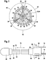
- the representation according to FIG. 1 is a section through a (executed in this example as insulation displacement connector) plug to remove, which comprises an electrode assembly for an electrochemical sensor.
- FIG. 1 illustrated cross section through an electrochemical sensor 10 shows an electrode assembly 16, 18, 20.
- the electrode assembly 16, 18, 20 is enclosed by a jacket 12, which can enclose an embedding material 14.
- the electrode arrangement comprises at least one working electrode 16, at least one counterelectrode 18 and at least one reference electrode 20.
- the electrode arrangement 16, 18, 20 extends in the illustration according to FIG FIG. 1 perpendicular to the plane of the drawing, wherein the at least one working electrode 16, the at least one counter electrode 18 and the at least one reference electrode 20 parallel to each other.
- the at least one working electrode 16, the at least one counter electrode 18 and the at least one reference electrode 20 form an electrochemical measuring cell and at the same time the body of the electrochemical sensor 10.
- the at least one working electrode 16 is made of a material suitable for electrochemical purposes, such as gold, silver , Palladium, platinum or carbon. The use of other precious metals or other metals or metal alloys, even in multi-layer arrangement, is conceivable.
- the at least one working electrode 16 is coated to detect the analyte with a suitable reagent as described in more detail below.
- the at least one counter-electrode 18 is also made of a suitable material for electrochemical purposes, such as gold, silver, palladium, platinum or carbon, and can remain uncoated or even coated one or more layers. Again, as an alternative or in addition, as with the other electrodes, it is also possible to use further metals (preferably noble metals) or metal alloys or multilayer metals.
- the at least one reference electrode 20 is preferably made of a silver wire, which on its lateral surface with silver chloride is occupied. The at least one reference electrode 20 is used for the currentless measurement of the potential of the at least one working electrode.
- connection 22 for producing an electrical contact of the at least one working electrode 16 a terminal 24 for electrically contacting the at least one counter electrode 18 and an electrical connection 26 for making electrical contact at least one reference electrode 20 are formed.
- a connection 22 for producing an electrical contact of the at least one working electrode 16 a terminal 24 for electrically contacting the at least one counter electrode 18 and an electrical connection 26 for making electrical contact at least one reference electrode 20 are formed.
- the number of electrodes 16, 18, 20 corresponding number of terminals 22, 24, 26 arranged in a circumferential pitch 42, which is 120 ° in the illustrated schematically illustrated embodiment.
- a corresponding number of terminals 22, 24, 26 is provided on the jacket 12 of the electrochemical sensor 10.
- the contacting elements 28 may be formed as cutting clamps, which include a cutting edge 30.
- the ends of the wires can also be exposed and separated onto one Terminal board soldered, bonded or glued. Subsequently, this arrangement can be cast, for example, in a connector housing, for example.
- the at least one working electrode 16, the at least one counterelectrode 18 and the at least one reference electrode 20 are insulated from each other by an insulating profile 32.
- the insulation profile 32 is formed in Y-geometry, which results in each case a receiving compartment, the at least one working electrode 16, the at least one counter electrode 18 and the at least one reference electrode 20 receives results.
- the insulation profile 32 is manufactured as a strand extrusion profile.
- the insulation profile 32 may also have a different configuration, such as X-shaped or T-shaped. A cross-shaped design of the geometry of the insulation profile 32 is possible.
- the geometry 34 of the insulation profile ensures that the at least one working electrode 16, the at least one counter electrode 18 and the at least one reference electrode 20, which run parallel to each other, are separated from each other by the insulation profile, for example by the insulation profile 32, by webs.
- sectional insulation profile 32 shown in Y-geometry 34 includes a first web 36 which separates the at least one counter electrode 18 from the at least one working electrode 16.
- a second web 38 of the insulation profile 32 is used to separate the at least one working electrode 16 from the at least one reference electrode 20, which in turn is separated from the at least one counterelectrode 18 of the electrode arrangement 16, 18, 20 by a third web 40 of the insulation profile 32.
- the schematic representation according to FIG. 2 It can be seen that the electrochemical sensor 10 is part of a device having an insertion head 60.
- the insertion head 60 is rounded at its end and has a diameter of preferably ⁇ 1 mm, in particular ⁇ 500 microns and particularly preferably ⁇ 50 microns.
- the insertion head 60 is used for subcutaneous insertion of the electrochemical sensor into a body tissue.
- the insertion head 60 is sealed off from the electrode arrangement 16, 18, 20 via a first seal 32, wherein in the illustration according to FIG FIG. 2 only the at least one working electrode 16 and the at least one reference electrode 20 are shown.
- the double arrow indicated by reference numeral 70 indicates the direction of movement in the device for determining an analyte concentration in a body tissue or in a body fluid.
- the electrochemical sensor 10 can be introduced into the tissue via a slotted hollow needle, wherein instead of an insertion head 60, only an insulation of the end face of the sensor 10 can be used.
- the electrochemical sensor 10 can also be pulled under the skin by means of an insertion aid, for example a needle or a blade.
- an insertion aid for example a needle or a blade.
- a form-fitting part can be used, which serves as a driver and when pulling out the introducer does not retract the electrochemical sensor 10 again.
- the electrochemical sensor 10 itself should be designed in such a way that, after the end of its use, it can also be removed from the tissue relatively easily.
- connection carrier 64 In addition to the insertion head 60 and the electrode arrangement 16, 18, 20, a device shown in FIG. 1 shown in cross-section connection carrier 64, the, as above in connection with FIG. 1 described, preferably designed as insulation displacement connector.
- the connection carrier 64 ensures the electrical contacting of the at least one working electrode 16, the at least one counterelectrode 18 and the at least one reference electrode 20.
- the connection carrier 64 has a circumference 66 at which the in FIG. 1 terminals 22, 24, 26 shown for electrically contacting the at least one working electrode 16, the at least one counter electrode 18 and the at least one reference electrode 20 are electrically contacted. As related to FIG.
- the electrical contacting elements 28 are preferably designed as cutting edges 30 wedge-shaped elements, each of which contact the peripheral surface of the at least one working electrode 16, the at least one counter electrode 18 and the at least one reference electrode 20 electrical.
- an evaluation unit which evaluates the signals that are transmitted via the at least one working electrode 16 and the at least one counterelectrode 18, evaluates and makes a determination of the analyte concentration in the body tissue or in a body fluid and directly displays it to the user.
- connection support 64 which can preferably be designed as a form-fitting part
- the electrode arrangement 16, 18, 20 comprising a reference electrode 20
- different lengths of the electrode assembly 16, 18, 20 between the first seal 62 to the insertion head 60 and the second seal 68 to the connection carrier 64 can be realized.
- the at least one working electrode 16, the at least one working electrode 18 and the at least one reference electrode 20 the electrochemical measuring cell, which is enclosed after insertion of the insertion head 60 from the body tissue and allows detection of an analyte in a body tissue or a body fluid. Due to the design of the at least one working electrode 16, the at least one counter-electrode 18 and the at least one reference electrode 20 as wire-shaped components, the electrode arrangement 16, 18, 20 has a very elongated surface.
- the electrochemical detection occurs in a large area of tissue.
- local inhomogeneities eg, insulating fat cells
- High power conversion is also typically associated with high glucose consumption. This can lead to depletion of tissue and thus to erroneously as too low measured values.
- the aim is therefore not to choose the electrode surface, but at the same time to capture a lot of space in the tissue. This goal is achieved in particular by long, thin wires.
- the glucose consumption can also be throttled by a thicker immobilization layer. The thinner electrode package is executed, the lower are usually disturbing interactions with the body tissue (eg cell growth or wound healing).
- the representation according to FIG. 3 is a first manufacturing step of the electrode configuration as in FIGS Figures 1 and 2 shown by an electrochemical sensor, refer to.
- the inventively proposed electrochemical sensor 10 is characterized by a manufacturing process, which allows the use of advantageous for large-scale production individual production steps.
- the components of the electrochemical sensor 10 are substantially the at least one working electrode 16, the at least one counter electrode 18 and the at least one reference electrode 20 and the insulating profile 32.
- the for producing a single or multi-layer coating of the at least one working electrode 16, the at least one counter electrode 18 and the at least one reference electrode 20 will be described in more detail below.
- the at least one working electrode 16 of the electrode assembly 16, 18, 20 is coated with a suitable reagent for detecting that analyte in a body tissue to be determined.
- This coating step is performed as shown in FIG. 3 made in the context of an annular nozzle coating 82.
- the at least one working electrode 16 moves in the conveying direction 80 through an annular nozzle 84.
- the annular nozzle 84 comprises a cavity 92 which is filled with a reagent medium 86.
- the promotion of the reagent medium 86 in the cavity 92 of the annular nozzle 84 is effected by a feed pump 90.
- the reagent medium 86 may be, for example, a mixture of manganese dioxide (manganese dioxide), graphite and GOD (glucose oxidase), which catalytically convert glucose to gluconolactone.
- the film of the reagent medium 86 is dried on the surface 94 of the at least one working electrode 16, followed by the manufacturing steps described below.
- FIG. 4 shows the merging of the at least one coated working electrode with the at least one counter electrode, the at least one reference electrode and the present in strand form isolation profile.
- At least one working electrode 16 coated with a reagent medium 86 is supplied to a merging station 130 as at least one coated working electrode 110. Further, the merging station 130, the at least one, preferably uncoated counter electrode 18 and the at least one reference electrode 20 are supplied. Furthermore, the merging station 130 is supplied with the insulation profile 32, which is preferably produced as a strand extrusion profile, which has the insulation profile Figure 4.1 shown Y-geometry 34 has.
- the at least now coated working electrode 16, the at least one, for example uncoated or coated, counter electrode 18 and the at least one reference electrode 20 are grouped around the insulation profile 32 that the at least one working electrode 16, the at least one counter electrode 18 and the at least one reference electrode 20 are isolated from each other.
- the merging station 130 leaves an electrode arrangement, the at least one coated working electrode 16, at least one, preferably uncoated counter electrode 18, at least one reference electrode 20 and includes the isolation profile 32.
- the electrode assembly 16, 18, 20 leaving the merging station 130 constitutes an electrode package 132.
- the representation according to FIG. 5 is another manufacturing step, which the electrode package according to FIG. 4 is supplied after the merger, refer to.
- FIG. 5 2 shows that the electrode package 132, which comprises the at least one coated working electrode 110 which comprises at least one preferably uncoated counterelectrode 18 and the at least one reference electrode 20, is supplied to an immobilization medium coating 140.
- an immobilization medium 142 shown in FIG. 5 applied in an annular nozzle 146 incoming electrode package 132.
- the electrode packet is additionally isolated and / or toxic components (for example the GOD acting as a cytotoxin) are prevented from diffusing into the body tissue.
- the outside of the electrochemical sensor 10, which comes in contact with the body tissue, should be biocompatible (ie not repelled by the body). This is another particularly preferred property of the immobilization medium 142. Alternatively or additionally, an additional layer can be applied, which ensures this additional property of biocompatibility.
- the other materials used, which come into contact with the body tissue, for example, materials for insulation in the connector area and at the insertion end, should have corresponding biocompatible properties or coated accordingly.
- the annular nozzle 146 used in the context of the immobilization medium coating 140 comprises a cavity 150, which has an outlet opening 148 and is filled with an immobilization medium 142.
- the cavity 150 of the annular nozzle 146 is filled continuously with the immobilization medium 142, so that the entire surface of the electrode package 132 entering the cavity in the conveying direction 80 is wetted by the immobilization medium 142.
- the lateral surface of the electrode packet 132 which enters the annular nozzle 146 in the conveying direction 80, is provided with a coating with immobilization medium 142.
- the conveying direction of the electrode package 132 is shown in FIG FIG. 5 designated by reference numeral 144.
- Reference numeral 152 denotes the electrode package 132 coated with the immobilization medium 142.
- the annular nozzle 146 in the conveying direction 144 entering electrode package 132 which comprises the at least one working electrode 16, the at least one counter electrode 18 and the at least one reference electrode 20, which are insulated from each other by the insulating profile 32, and individual of the at least one working electrode 16, the At least one counter electrode 18 and the at least one reference electrode 20 of the immobilization medium coating 140 are supplied.
- the immobilization medium coating 140 which according to FIG. 5 can be applied, the contact between the at least one coated working electrode 110 and the at least one, preferably uncoated counter electrode 18 and the body tissue or the body fluid, whereby the presence of a particular analyte is to be determined.
- the representation according to FIG. 6 is a confectioning step removable.
- coated electrode package 152 which is coated on the periphery, for example, with the immobilization medium 142, assembled into individual sections 164.
- the assembly 160 is preferably carried out by a transverse cutting of the coated electrode package 152. In this case, different lengths 162 of the assembled sections 164 can be adjusted depending on the application.
- FIG. 2 not shown in full length device comprising an electrochemical sensor 10 obtained.
- the electrochemical measuring cell of the electrochemical sensor 10 is formed by the lateral surface of the layer of immobilization medium 142 applied as part of the immobilization medium coating 140. This layer of immobilization medium 142 represents the boundary of the electrochemical measuring cell and the contact surface with which the electrochemical sensor 10 is in contact with the body tissue or body fluid.
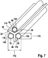
- the representation according to FIG. 7 is a perspective view of the electrode assembly of the electrochemical sensor 10 can be seen.
- FIG. 7 shows that the at least one working electrode 16, the at least one counter electrode 18 and the at least one reference electrode 20 are separated from each other via the insulating profile 32.
- an insulating profile 32 having Y-geometry 34 comprises the first web 36, the second web 38 and the third web 40.
- the first web 36 and the second web 38 delimit a first receiving compartment 174 in which the at least one working electrode 16 is accommodated.
- the at least one working electrode 16 has a coating with a reagent medium 86 of a reagent for detecting the analyte in the body tissue or in the body fluid. From the illustration according to FIG. 7 It can be seen that the immobilization medium 142 can be applied to this reagent medium 86.
- FIG. 7 illustrated embodiment of the electrode assembly 16, 18, 20 of the electrode assembly 132 is the Immobilleitersmedium 142 on the lateral surface of the at least one working electrode 16, the at least one counter electrode 18 and the at least one reference electrode 20 applied.
- FIG. 5 also described the entire from the merge station 130 according to FIG. 4 emerging electrode package 132 are coated as a whole with the Immobilticiansmedium 142, which then the in FIG. 1 illustrated embedding material 14 represents.
- FIG. 7 The perspective view according to FIG. 7 Furthermore, it can be seen that the second web 38 with the third web 40 of the insulating profile 42 defines a third receiving compartment 178, in which in the exemplary embodiment according to FIG. 7 the at least one reference electrode 20 is received. Finally, the third land 40 and the first land 36 define the insulation profile 32 as shown in FIG FIG. 7 a second receiving compartment 176, in which the at least one counter electrode 18 of the electrode assembly 16, 18, 20 is located. From the illustration according to FIG.
- a diameter 170 of the reference electrode is on the order of about 100 .mu.m
- reference numeral 172 denotes the sum of the diameters of the at least one reference electrode 20, the at least one counter electrode 18 and the material thickness of the third web 40 of the insulation profile 32.
- the route 172 as shown in FIG. 7 has a length of the order of about 250 microns.
- the proposed electrode assembly 16, 18, 20 of the present invention proposed electrochemical sensor 10 has very compact dimensions, which is due to the parallel arrangement of at least one Working electrode 16, the at least one counter electrode 18 and the at least one reference electrode 20 in the receiving compartments 174, 176 and 178 of the insulation profile 32 is based.
- the representation according to FIG. 8 is a schematic representation of the manufacturing process for producing the electrochemical sensor, in particular the electrode assembly can be seen.
- the at least one working electrode 16 is coated with the reagent medium 86, which is a suitable reagent for detecting the analyte.
- the reagent medium 86 which is located after the annular nozzle coating 82 on the surface 94 of the at least one working electrode 16, dried.
- the electrode package 132 obtained from the merge station 130 is subsequently subjected to an immobilization medium coating 140.
- an immobilization medium coating 140 it is possible to apply the immobilization medium 142 both to the electrode package 132 obtained in the merging station 130 as a whole and consequently to embed it in the immobilization medium.
- a separation takes place either of the coated electrode package 152 or of the combined individually coated individual electrodes 16, 18 and 20.
- sections 164 are produced which are formed in different lengths 162 can be, with the length 162 depends on the application of the electrode assembly for use in an electrochemical sensor 10.
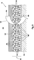
- FIG. 9 schematically a section of an electrode surface of a working electrode 16 is shown in sectional view.
- the working electrode has a gold wire 180 in this example.
- the gold wire 180 is according to the in FIG. 8 Process described coated with a reagent medium 86.
- the reagent medium in this example consists of three different components: conductive carbon particles 182, brownstone particles 184, GOD particles or GOD conglomerates 186 and a binder polymer 188.
- the binder polymer 188 ensures the processing properties of the reagent medium in undried condition.
- the reagent medium 86 is adjusted by selecting the binder polymer 188 in its viscosity and / or surface tension so that it can be processed well in the "wet" (ie undried) state by annular die coating 82 and a homogeneous, uniform, good on the gold wire Forms 180 adherent layer.
- the binder polymer is selected such that it can be dried at moderate temperatures without, for example, thermally destroying GOD 186 in this drying step.
- suitable binder polymer 188 include mixtures, for example mixtures of polymers with various solvents.
- FIG. 9 also the layer of Immobilticiansmediums 142 shown. This surrounds the reagent medium 86 and prevents body fluid (symbolically denoted here by 190) from coming into direct contact with the brownstone particles 184 and with the GOD particles 186 and that GOD can diffuse into the body fluid 190. At the same time, oxygen and glucose as analyte to be detected can diffuse out of the body fluid 190 through the layer of the immobilization medium 142 and thus reach the reagent medium 86.
- body fluid symbolically denoted here by 190
- FIG. 9 symbolically represents the reaction used to detect glucose 194 in body fluid 190 by a "reaction arrow" 192.
- Glucose 194 is oxidized to gluconolactone via the enzyme GOD 186 and subsequently oxygen is reduced to H 2 O 2 by the enzyme GOD 186.
- the H 2 O 2 is catalytically oxidized by the manganese dioxide 184 and thereby the electrons are transferred to the dissipative gold wire 180 via the carbon particles 182 which are in contact with the manganese dioxide 184.
- the potential of the gold wire 180 (or the entire working electrode 16) influenced in this way can be detected in the manner described above, for example by an amperometric measurement, and the concentration of glucose in the body fluid 190 can be deduced therefrom.
Abstract
Description
Die Erfindung bezieht sich auf einen elektrochemischen Sensor zur Ermittlung einer Konzentration mindestens eines Analyten in einem Medium, insbesondere einem Körpergewebe und/oder einer Körperflüssigkeit, ferner einer Vorrichtung, an welcher der elektrochemische Sensor eingesetzt wird, eine Verwendung des elektrochemischen Sensors sowie der Vorrichtung und ein Verfahren zur Herstellung des elektrochemischen Sensors. Derartige Sensoren oder Vorrichtungen werden insbesondere im Bereich der Medizintechnik eingesetzt, beispielsweise um elektrochemisch eine Konzentration von Glucose (insbesondere Blutglucose oder Glucose in einer Gewebeflüssigkeit), Lactat oder anderen Analyten, insbesondere von Metaboliten, zu bestimmen.The invention relates to an electrochemical sensor for determining a concentration of at least one analyte in a medium, in particular a body tissue and / or a body fluid, a device to which the electrochemical sensor is used, a use of the electrochemical sensor and the device and a Method for producing the electrochemical sensor. Such sensors or devices are used in particular in the field of medical technology, for example in order to determine electrochemically a concentration of glucose (in particular blood glucose or glucose in a tissue fluid), lactate or other analytes, in particular of metabolites.
Die Bestimmung der Blutglucosekonzentration sowie eine entsprechende Medikation ist für Diabetiker ein essenzieller Bestandteil des Tagesablaufes. Dabei ist die Blutglucosekonzentration schnell und einfach mehrmals am Tage, typischerweise 2- bis 7-mal zu bestimmen, um gegebenenfalls entsprechende medizinische Maßnahmen ergreifen zu können. In vielen Fällen erfolgt dabei eine Modifikation mittels automatischer Systeme, insbesondere mit Insulinpumpen.The determination of the blood glucose concentration and a corresponding medication is an essential part of the daily routine for diabetics. The blood glucose concentration is quickly and easily determined several times a day, typically 2 to 7 times, in order to be able to take appropriate medical measures if necessary. In many cases, this involves a modification by means of automatic systems, in particular with insulin pumps.
Um den Tagesablauf des Diabetikers nicht mehr als unbedingt nötig einzuschränken, werden häufig entsprechend mobile Geräte eingesetzt, welche einfach zu transportieren und zu handhaben sein sollten, so dass eine Messung der Blutglucosekonzentration, beispielsweise am Arbeitsplatz oder in der Freizeit, problemlos erfolgen kann.In order to limit the daily routine of the diabetic no more than absolutely necessary, often correspondingly mobile devices are used, which should be easy to transport and handle, so that a measurement of the blood glucose concentration, for example, at work or in the leisure, can be done easily.
Derzeit sind verschiedene mobile Geräte erhältlich, welche teilweise nach unterschiedlichen Messmethoden und unter Verwendung unterschiedlicher Diagnoseverfahren funktionieren. Ein erstes Messverfahren beruht beispielsweise auf einer elektrochemischen Messmethode, wobei eine Blutprobe, welche vom Patienten durch Perforieren einer Hautschicht mittels einer Lanzette dem Körpergewebe entnommen wird, auf eine mit Enzymen und Mediatoren beschichtete Elektrode appliziert wird. Entsprechende Teststreifen für derartige elektrochemische Messverfahren sind beispielsweise in
Die beschriebenen Nachweisverfahren beruhen überwiegend darauf, dass ein Patient zunächst eine entsprechende Probe der zu untersuchenden Körperflüssigkeit entnimmt, wobei es sich sowohl um eine Blutprobe als auch um eine Urinprobe handeln kann und diese dann entsprechend mittels der Testvorrichtung untersucht. Dieses Verfahren beinhaltet jedoch verschiedene Nachteile. So ist dieses Verfahren zum einen äußerst aufwändig und setzt mehrere Handhabungsschritte voraus. So muss beispielsweise eine Lanzette bereitgestellt und gespannt werden, anschließend mittels dieser Lanzette eine Hautschicht perforiert werden, dann ein so erzeugter Blutstropfen auf einen Teststreifen aufgetragen werden und anschließend dieser Teststreifen mittels eines entsprechenden Gerätes ausgewertet werden. Für viele Patienten, insbesondere ältere Menschen und Kinder, sind diese Handhabungsschritte oftmals nur schwer durchzuführen, da die Patienten beispielsweise in ihrer motorischen Fähigkeit und ihrem Sehvermögen eingeschränkt sind. Weiterhin lassen sich diese Verfahrensschritte nur in wenigen Fällen diskret durchführen, so dass beispielsweise ein Schutz der Privatsphäre des Patienten bei einer Messung am Arbeitsplatz in nur unzureichendem Maße gewahrt ist. Auch kann eine Fehlbedienung im Rahmen des Messverfahrens leicht zu falschen Messwerten führen, mit teilweise fatalen Folgen einer auf falschen Messergebnissen aufbauenden falschen Medikation.The described detection methods are predominantly based on the fact that a patient first extracts a corresponding sample of the body fluid to be examined, which can be both a blood sample and a urine sample and then examined accordingly by means of the test device. However, this method involves several disadvantages. Thus, this process is extremely time-consuming and requires several handling steps. Thus, for example, a lancet must be provided and tensioned, then a skin layer is perforated by means of this lancet, then a blood drop produced in this way can be applied to a test strip and then this test strip can be evaluated by means of a corresponding device. For many patients, especially the elderly and children, these manipulations are often difficult to accomplish because patients are limited in their motor ability and vision, for example. Furthermore, these method steps can be carried out discretely only in a few cases, so that, for example, a protection of the privacy of the patient in a measurement at the workplace is maintained to an insufficient extent. Also, an incorrect operation in the context of the measurement process can easily lead to false readings, with sometimes fatal consequences of false medication based on incorrect measurement results.
Aus dem Stand der Technik sind daher Systeme bekannt, welche kontinuierlich Messdaten generieren und welche alternativ oder zusätzlich zu den oben beschriebenen Systemen oder Verfahren eingesetzt werden können, z.B. um die Zahl der Einzelmessvorgänge zu reduzieren. So sind beispielsweise Systeme kommerziell erhältlich, welche einen Membran-Schlauch im Unterhautgewebe umfassen, durch den eine Transportflüssigkeit gepumpt wird. Über die Membran diffundiert Glucose in die Transportflüssigkeit, welche dann wiederum zu einer elektrochemischen Messzelle befördert wird. In der elektrochemischen Messzelle wird dann die Glucosekonzentration gemessen. Nachteilig an einer derartigen Anordnung zur kontinuierlichen Messwerterzeugung ist jedoch, dass hierbei vom Patienten ständig ein Vorrat an Transportflüssigkeit sowie ein entsprechender Abfallbehälter zur Aufnahme kontaminierter Transportflüssigkeit mitgeführt werden muss.From the prior art systems are therefore known which continuously generate measurement data and which can be used alternatively or in addition to the systems or methods described above, for example in order to reduce the number of individual measurement operations. For example, systems are commercially available which include a membrane tube in the subcutaneous tissue through which a transport fluid is pumped. Glucose diffuses into the transport fluid via the membrane, which in turn is transported to an electrochemical measuring cell. The glucose concentration is then measured in the electrochemical measuring cell. However, a disadvantage of such an arrangement for the continuous generation of measured values is that in this case the patient constantly has to carry along a supply of transport liquid as well as a corresponding waste container for receiving contaminated transport liquid.
Weitere aus dem Stand der Technik bekannte Sensortypen zur kontinuierlichen Messwerterzeugung sind ausgestaltet, um in ein Körpergewebe implantiert zu werden. So offenbart beispielsweise
Ein Hauptvorteil der kontinuierlich messenden Systeme besteht darin, dass auch kürzere periodische Schwankungen der Glucosekonzentration (zeitliche Verläufe) im Zusammenhang mit der Nahrungsaufnahme und körperlicher Betätigung erfasst werden können. Dies ist für das "Einstellen" eines Diabetikers von großer Bedeutung.One of the main advantages of continuous measurement systems is that even shorter periodic fluctuations in glucose concentration (time courses) can be detected in connection with food intake and physical activity. This is very important for "setting" a diabetic.
Die aus dem Stand der Technik bekannten implantierbaren Sensoren sind bezüglich ihres Aufbaus und ihrer Herstellung jedoch äußerst aufwändig. Wird vorausgesetzt, dass es sich bei diesen Sensoren um nur für kurze Zeit (typischerweise etwa eine Woche) verwendbare Einwegsensoren handelt, so wird deutlich, dass die bei den aus dem Stand der Technik bekannten Sensoren eingesetzten Verfahren derartigen Anforderungen an Einwegartikeln nicht gerecht werden. So ist beispielsweise für die Herstellung des aus
Auch sind lithographische Verfahren, insbesondere das mit diesen Verfahren verbundene Ätzen von Metallschichten, nicht immer so zuverlässig, wie dies für die Herstellung medizintechnischer Produkte erforderlich ist. Insbesondere kann es vereinzelt vorkommen, dass einzelne Elektroden noch durch "Brücken" oder Stege miteinander verbunden sind, so dass die Funktionalität der Sensoren aufgrund von Herstellungsproblemen leicht beeinträchtigt oder sogar ganz verhindert sein kann. Ein weiterer Nachteil der aus dem Stand der Technik bekannten Sensoren, wie sie beispielsweise aus der
Anstelle der vorhergehend beschriebenen implantierbaren Sensoren, bei denen zur Strukturierung der Elektrodenpads Mikrostrukturierungsverfahren, so zum Beispiel ein lithographisches Verfahren, eingesetzt werden, können implantierbare Sensoren, wie zum Beispiel aus
Aus
Die vorstehend diskutierten Lösungen gemäß dem Stand der Technik sind nur in einem sehr eingeschränkten Bereich mit einem Körpergewebe in Kontakt. Die Elektrodenanordnung, üblicherweise eine Arbeitselektrode, eine Gegenelektrode und eine Referenzelektrode umfassend, ist lokal sehr eingeschränkt, d.h. vermag nur aussagefähige Ergebnisse in einem sehr kleinen Bereich des Körpergewebes zu erfassen. Die Funktion der aus dem Stand der Technik bekannten, auch implantierbaren, Sensoren kann durch lokale Gewebeinhomogenitäten, wie zum Beispiel Wundeffekte oder Fetteinlagerungen, gestört werden. Ferner wirken sich Sensormembraneigenschaften, insbesondere gemäß
Ein implantierbarer Sensor mit helixartig um einen Stab gewickelten Elektroden wird in
Die Aufgabe der Erfindung liegt darin, einen Sensor zur Verfügung zu stellen, welcher einfach und kostengünstig mittels eines zuverlässigen Herstellungsverfahrens herstellbar ist und welcher die Nachteile der aus dem Stand der Technik bekannten Sensoren und Verfahren vermeidet.The object of the invention is to provide a sensor which can be produced simply and inexpensively by means of a reliable production method and which avoids the disadvantages of the sensors and methods known from the prior art.
Die Aufgabe wird durch die Erfindung mit den Merkmalen der unabhängigen Ansprüche gelöst. Vorteilhafte Weiterbildungen der Erfindung sind den Unteransprüchen zu entnehmen.The object is achieved by the invention with the features of the independent claims. Advantageous developments of the invention can be found in the dependent claims.
Der erfindungsgemäß vorgeschlagenen Lösung folgend wird also ein elektrochemischer Sensor zur Ermittlung einer Konzentration mindestens eines Analyten in einem Medium, insbesondere in einem Körpergewebe und/oder einer Körperflüssigkeit vorgeschlagen. Vorzugsweise ist der elektrochemische Sensor derart ausgestaltet, dass dieser in ein Körpergewebe implantiert und/oder subkutan eingeführt werden kann. Zu diesem Zweck ist daher zumindest die freiliegende Sensoroberfläche vorzugsweise biokompatibel ausgestaltet, so dass insbesondere keine Zellgifte in das Körpergewebe diffundieren können bzw. in Kontakt mit dem Körpergewebe gelangen.The solution proposed according to the invention therefore proposes an electrochemical sensor for determining a concentration of at least one analyte in a medium, in particular in a body tissue and / or a body fluid. Preferably, the electrochemical sensor is designed such that it can be implanted in a body tissue and / or introduced subcutaneously. For this purpose, therefore, at least the exposed sensor surface is preferably made biocompatible, so that in particular no cell toxins can diffuse into the body tissue or come into contact with the body tissue.
Bei dem Analyten kann es sich zum Beispiel um Glucose, Lactat, Hormone oder andere Analyten handeln, welche insbesondere in der Medizin eine Rolle spielen. Alternativ oder zusätzlich kann der elektrochemische Sensor jedoch auch zur Messung anderer Arten von Analyten eingesetzt werden.The analyte may be, for example, glucose, lactate, hormones or other analytes, which play a role in particular in medicine. Alternatively or additionally, however, the electrochemical sensor can also be used for measuring other types of analytes.
Ein Grundgedanke der Erfindung besteht darin, den elektrochemischen Sensor so auszugestalten, dass eine Anordnung von mindestens zwei dünnen Drähten eine elektrochemische Messzelle bildet. Die Anordnung von dünnen Drähten stellt gleichzeitig die elektrische Verbindung zu einer geeigneten Messelektronik her. Die Messung der Analytkonzentration erfolgt dann durch elektrochemische (beispielsweise amperometrische) Messmethoden zwischen den mindestens zwei Elektroden, einer Arbeitselektrode und einer Gegenelektrode, insbesondere mittels einer Gleichspannung. Eine Referenzelektrode zur stromlosen Messung des Arbeitselektrodenpotenzials kann zusätzlich eingesetzt werden.A basic idea of the invention is to design the electrochemical sensor in such a way that an arrangement of at least two thin wires forms an electrochemical measuring cell. The arrangement of thin wires simultaneously establishes the electrical connection to a suitable measuring electronics. The analyte concentration is then measured by electrochemical (for example amperometric) measuring methods between the at least two electrodes, a working electrode and a counterelectrode, in particular by means of a DC voltage. A reference electrode for the currentless measurement of the working electrode potential can additionally be used.
Um eine möglichst kompakte Bauweise des elektrochemischen Sensors zu erreichen, werden die Einzelelektroden der Elektrodenanordnung zumindest in einem Abschnitt im Wesentlichen parallel, vorzugsweise exakt parallel (d. h. eine Winkelabweichung von der Parallelen um vorzugsweise nicht mehr als 5°, besonders bevorzugt von nicht mehr als 1°), zueinander ausgerichtet und durch ein Isolationsprofil gegeneinander isoliert. Auf diese Weise lassen sich günstigere Eigenschaften des elektrochemischen Sensors erreichen, da der Sensor entlang seiner Längserstreckung eine gute Homogenität aufweist. Insbesondere weist die Zellenbreite des Sensors (d. h. Dicke der Schichten, Elektrodenabstand etc.) eine hohe Gleichförmigkeit und geringe Toleranzen auf.In order to achieve as compact a construction as possible of the electrochemical sensor, the individual electrodes of the electrode arrangement are substantially parallel, preferably exactly parallel, at least in one section (ie an angle deviation from the parallels of preferably not more than 5 °, more preferably not more than 1 ° ), aligned with each other and isolated by an isolation profile against each other. In this way, more favorable properties of the electrochemical sensor can be achieved, since the sensor along its longitudinal extent has a good homogeneity. In particular, the cell width of the sensor (ie thickness of the layers, electrode spacing, etc.) has high uniformity and low tolerances.
Die Elektrodenanordnung umfasst mindestens zwei Elektroden, wobei es sich um mindestens eine Arbeitselektrode und mindestens eine weitere Elektrode handelt, wobei die mindestens eine weitere Elektrode insbesondere mindestens eine Gegenelektrode und/oder mindestens eine Referenzelektrode umfassen sollte. Bei dem erfindungsgemäß vorgeschlagenen elektrochemischen Sensor sind die Arbeitselektrode und die mindestens eine weitere Elektrode durch das Isolationsprofil voneinander getrennt. Zusätzlich kann auch eine direkte teilweise Einbettung der Elektroden in ein Isolationsmaterial erfolgen. Bei dem erfindungsgemäß vorgeschlagenen elektrochemischen Sensor ist das Isolationsprofil des elektrochemischen Sensors durch ein elektrisch nicht leitendes Material, wie zum Beispiel ein Kunststoffmaterial, dargestellt.The electrode arrangement comprises at least two electrodes, which are at least one working electrode and at least one further electrode, wherein the at least one further electrode should in particular comprise at least one counterelectrode and / or at least one reference electrode. In the electrochemical sensor proposed according to the invention, the working electrode and the at least one further electrode are separated from one another by the insulation profile. In addition, a direct partial embedding of the electrodes in an insulating material can take place. In the electrochemical sensor proposed according to the invention, the insulation profile of the electrochemical sensor is represented by an electrically non-conductive material, such as a plastic material.
Zur Definition der Begriffe "Isolationsprofil" und "isolierend" kann auf nachfolgende Ausführungen verwiesen werden. Danach sollte eine direkte Berührung der Elektroden untereinander vermieden werden. Naturgemäß ist jede Isolation nur bedingt perfekt, d.h. mit einem unendlichen Widerstand versehen. Ströme, die nicht durch einen Übergang zwischen den Elektroden und den Elektrolyten fließen, werden in der Regel als Leckströme bezeichnet und verfälschen die eigentliche elektrochemische Messung. Leckströme bilden sich durch die angeschlossene Elektronik, die Steckverbindung und im Sensorkörper selbst. Leckströme sollten vorzugsweise um einen Faktor 1000 niedriger sein als der eigentliche Sensorstrom.For the definition of the terms "insulation profile" and "insulating", reference is made to the following explanations. Thereafter, direct contact of the electrodes with each other should be avoided. Naturally, any isolation is only conditionally perfect, i. provided with an infinite resistance. Currents that do not flow through a junction between the electrodes and the electrolyte are usually referred to as leakage currents and distort the actual electrochemical measurement. Leakage currents are formed by the connected electronics, the plug connection and in the sensor body itself. Leakage currents should preferably be lower by a factor of 1000 than the actual sensor current.
Der erfindungsgemäß vorgeschlagene elektrochemische Sensor kann auf unterschiedlichste Weise vorteilhaft erfindungsgemäß weitergebildet werden. Die beschriebenen vorteilhaften Weiterbildungen können dabei einzeln oder in Kombination zueinander verwendet werden.The inventively proposed electrochemical sensor can be advantageously developed according to the invention in various ways. The described advantageous developments can be used individually or in combination with one another.
Der erfindungsgemäß vorgeschlagene elektrochemische Sensor weist mindestens eine, zumindest die mindestens eine Arbeitselektrode elektrisch kontaktierende Beschichtung auf. Während die mindestens eine Arbeitselektrode bevorzugt aus einem für elektrochemische Zwecke geeignetem Material, wie zum Beispiel Gold, Silber, Palladium, Platin oder Kohlenstoff, gefertigt ist, kann der die Gegenelektrode darstellende Draht unbeschichtet bleiben und ebenfalls aus einem der vorstehend erwähnten, für elektrochemische Zwecke geeignete Material gefertigt sein. Ist an der Elektrodenanordnung des erfindungsgemäß vorgeschlagenen elektrochemischen Sensors eine Referenzelektrode ausgeführt, so handelt es sich bei dieser bevorzugt um eine Ionenelektrode 2. Art, die vorzugsweise aus einem an der Oberfläche mit Silberchlorid belegten Silberdraht ausgeführt ist.The inventively proposed electrochemical sensor has at least one, at least the at least one working electrode electrically contacting coating. While the at least one working electrode is preferably made of a material suitable for electrochemical purposes, such as gold, silver, palladium, platinum or carbon, the wire representing the counter electrode may remain uncoated and also of any of the aforementioned electrochemical applications Be made of material. If a reference electrode is embodied on the electrode arrangement of the electrochemical sensor proposed according to the invention, this is preferably an ion electrode of the second kind, which is preferably made of a silver wire coated with silver chloride on the surface.
Eine Elektrode ist definiert als eine Grenzfläche zwischen einem Leiter 1. Ordnung (Ladungstransport durch Elektronen in Metall) und einem Leiter 2. Ordnung (Ladungstransport durch Ionen in einem Elektrolyten). Für die Elektroden (Leiter 1. Ordnung in Kontakt mit Leiter 2. Ordnung) sollten vorzugsweise keine Materialien eingesetzt werden, die an der Oberfläche passivieren (isolierende Oxidschichten bilden), wie beispielsweise Aluminium. Arbeitselektrode und Gegenelektroden sind Redox-Elektroden, so dass vorzugsweise für diese Elektroden keine Materialien (Leiter 1. Ordnung) eingesetzt werden, die bei gegebener Polarisierung korrodieren (d.h. sich auflösen).An electrode is defined as an interface between a first order conductor (charge transport by electrons in metal) and a second order conductor (charge transport by ions in an electrolyte). For the electrodes (1st order conductors in contact with 2nd order conductors) preferably no materials should be used that passivate on the surface (form insulating oxide layers), such as aluminum. Working electrode and counter electrodes are redox electrodes, so preferably no materials (first order conductors) are used for these electrodes which corrode (i.e., dissolve) given polarization.
Aufgrund der Konfiguration der eingesetzten mindestens einen Arbeitselektrode und der eingesetzten mindestens einen Gegenelektrode im Rahmen der vorgeschlagenen Elektrodenanordnung für einen erfindungsgemäßen elektrochemischen Sensor wird eine schlank bauende Ausführung des elektrochemischen Sensors möglich. Diese besondere geometrische Form ermöglicht die parallele Platzierung der mindestens einen Arbeitselektrode parallel zur mindestens einen Gegenelektrode, wodurch die eingangs beschriebenen Gewebeinhomogenitäten in ihrer Wirkung auf das Messergebnis, welches vom elektrochemischen Sensor erzeugt wird, erheblich reduziert werden. Durch die erfindungsgemäß vorgeschlagene Ausgestaltung der Elektrodenanordnung als dreidimensionale Geometrie kann der Durchmesser des kompakt bauenden Sensors sehr klein gehalten werden. Aufgrund der Mantelfläche der Elektrodenanordnung mit mindestens einer Arbeitselektrode und mindestens einer Gegenelektrode kann die für die Signalhöhe notwendige Elektrodenfläche bereitgestellt werden.Due to the configuration of the at least one working electrode used and the at least one counterelectrode used within the scope of the proposed electrode arrangement for an electrochemical sensor according to the invention, a slim design of the electrochemical sensor becomes possible. This particular geometric shape allows the parallel placement of the at least one working electrode parallel to the at least one counter electrode, whereby the tissue inhomogeneities described above are significantly reduced in their effect on the measurement result, which is generated by the electrochemical sensor. By inventively proposed embodiment of the electrode assembly as a three-dimensional geometry, the diameter of the compact sensor can be kept very small. Due to the lateral surface of the electrode arrangement with at least one working electrode and at least one counterelectrode, the electrode area necessary for the signal height can be provided.
In einer bevorzugten Ausführungsform umfasst der erfindungsgemäß vorgeschlagene elektrochemische Sensor drei drahtförmig ausgebildete Elektroden, die durch ein Isolationsprofil in Y-Geometrie gegeneinander isoliert sind. Das Isolationsprofil mit Y-Geometrie liegt bevorzugt als Kunststoffstrangpressprofil vor und lässt sich, wie nachstehend noch eingehender beschrieben wird, besonders vorteilhaft im Rahmen einer Großserienfertigung bei der Herstellung des erfindungsgemäß vorgeschlagenen elektrochemischen Sensors einsetzen. Ein Isolationsprofil in Y-Geometrie bietet die vorteilhafte Möglichkeit, drei Aufnahmefächer zur Aufnahme der mindestens einen Arbeitselektrode, der mindestens einen Gegenelektrode und der gegebenenfalls eingesetzten Referenzelektrode zur Messung des Arbeitselektrodenpotenzials bereitzustellen. Das bevorzugt in Y-Geometrie vorliegende Kunststoffstrangpressprofil, welches das Isolationsprofil bildet, verleiht dem elektrochemischen Sensor eine ausreichende mechanische Stabilität und Zugfestigkeit. Dies erleichtert die Handhabung des elektrochemischen Sensors auch für ungeübte Anwender nicht unerheblich. Der Sensor kann beispielsweise zusammen mit einer Einführhilfe eingesetzt werden (z.B. mit einer Nadel unter die Haut gezogen werden, wobei die Nadel wieder entfernt wird). Der Sensor sollte hierfür also eine gewisse Zugfestigkeit aufweisen. Gleichzeitig sollte er aber flexibel sein, damit bei Verformung des umgebenden Gewebes (durch Bewegen oder Drücken der Haut) der Sensor im Gewebe keine Wunde reißt (wodurch der Sensor beispielsweise inkorrekte Messwerte liefern könnte). Diese Eigenschaften werden durch die bevorzugte Y-Geometrie gewährleistet.In a preferred embodiment, the inventively proposed electrochemical sensor comprises three wire-shaped electrodes, which are insulated from each other by an insulation profile in Y-geometry. The insulation profile with Y geometry is preferably present as a plastic extruded profile and, as will be described in more detail below, can be used particularly advantageously in the context of large-scale production in the production of the electrochemical sensor proposed according to the invention. An insulation profile in Y geometry offers the advantageous possibility of providing three receiving compartments for receiving the at least one working electrode, the at least one counterelectrode and the optionally used reference electrode for measuring the working electrode potential. The preferably in Y-geometry plastic extruded profile, which forms the insulation profile, gives the electrochemical sensor sufficient mechanical stability and tensile strength. This facilitates the handling of the electrochemical sensor even for inexperienced User not insignificant. For example, the sensor may be used in conjunction with an introducer (eg, with a needle pulled under the skin, removing the needle). The sensor should therefore have a certain tensile strength for this purpose. At the same time, however, it should be flexible so that if the surrounding tissue deforms (by moving or pushing the skin) the sensor in the tissue will not rupture a wound (which could cause the sensor to give incorrect readings, for example). These properties are ensured by the preferred Y geometry.
Die Elektrodenanordnung des erfindungsgemäß vorgeschlagenen elektrochemischen Sensors kann mit einer Beschichtung zur Immobilisierung reaktiver Bestandteile versehen sein. Diese Beschichtung zur Immobilisierung reaktiver Bestandteile kann auf die einzelnen Elektroden, d.h. mindestens eine Arbeitselektrode, die mindestens eine Gegenelektrode sowie gegebenenfalls die mindestens eine Referenzelektrode oder das fertige Elektrodenpaket, welches das Isolationsprofil umfasst, aufgebracht werden. Die Elektrodenanordnung des erfindungsgemäß vorgeschlagenen elektrochemischen Sensors kann neben den Elektroden und dem Isolationsprofil zusätzliche Barriereschichten umfassen, bei denen es sich zum Beispiel um Schichten eines Polymers, insbesondere eines isolierenden Polymers handeln kann. Beispiele geeigneter Polymere sind Polyester, Polyethylen, Polypropylen oder Polyurethan. Auch andere isolierende Polymere sind einsetzbar, wobei bezüglich des Begriffs "isolierend" wiederum auf die obige Beschreibung verwiesen werden kann.The electrode arrangement of the electrochemical sensor proposed according to the invention may be provided with a coating for the immobilization of reactive constituents. This coating for immobilizing reactive components may be applied to the individual electrodes, i. at least one working electrode, the at least one counter electrode and optionally the at least one reference electrode or the finished electrode packet, which comprises the insulation profile, are applied. The electrode arrangement of the electrochemical sensor proposed according to the invention can comprise, in addition to the electrodes and the insulation profile, additional barrier layers, which can be, for example, layers of a polymer, in particular of an insulating polymer. Examples of suitable polymers are polyester, polyethylene, polypropylene or polyurethane. Other insulating polymers can also be used, wherein reference can again be made to the above description with regard to the term "insulating".
Bei der Immobilisierungsmedium-Beschichtung des Elektrodenpakets oder der einzelnen Elektroden der mindestens einen Arbeitselektrode, der mindestens einen Gegenelektrode oder der mindestens einen Referenzelektrode zur Immobilisierung reaktiver Bestandteile handelt es sich in vorteilhafter Weise um eine Membranschicht, die eine teilweise Durchlässigkeit für den mindestens einen Analyten aufweist. Die Membranschicht kann eine Durchlässigkeit für Glucose, Lactat und/oder weitere nachzuweisende Analyten aufweisen. Die Membranschicht, mit der das Elektrodenpaket oder die erwähnten Einzelelektroden beschichtet werden können, sollte vorteilhafterweise undurchlässig sein für beim elektrochemischen Messverfahren eingesetzte Hilfschemikalien, so zum Beispiel für eingesetzte Enzyme, welche auf eine oder mehrere der erwähnten Elektroden aufgebracht werden und teilweise eine Toxizität aufweisen, nicht in das Körpergewebe gelangen und dieses nicht kontaminieren.The immobilization medium coating of the electrode packet or of the individual electrodes of the at least one working electrode, the at least one counterelectrode or the at least one reference electrode for the immobilization of reactive constituents is advantageously a membrane layer which has a partial permeability to the at least one analyte. The membrane layer may have a permeability to glucose, lactate and / or other analytes to be detected. The membrane layer with which the electrode packet or the mentioned individual electrodes can be coated should advantageously be impermeable to auxiliary chemicals used in the electrochemical measuring method, for example for enzymes used which are applied to one or more of the mentioned electrodes and partly have a toxicity enter the body tissue and do not contaminate it.
Die aufzubringende Membranschicht zur Immobilisierung reaktiver Bestandteile, die beispielsweise die Elektrodenanordnung mantelförmig umgeben oder die einzelnen Elektroden der Elektrodenanordnung, die mindestens eine Arbeitselektrode, die mindestens eine Gegenelektrode sowie die mindestens eine Referenzelektrode mantelförmig umschließen. Die aufgebrachte Immobilisierungsmedium-Beschichtung kann zum Beispiel ein Polyurethan aufweisen. Auch ein mehrschichtiger Membranschichtaufbau ist möglich. Hier kann das Aufbringen der zum Beispiel ein Polyurethan aufweisenden Immobilisierungsmedium-Beschichtung in einem Beschichtungsverfahren, wie zum Beispiel dem Tauchverfahren, einem Sprühverfahren oder auch eine Ringdüsenbeschichtung, eingesetzt werden.The membrane layer to be applied for the immobilization of reactive constituents which, for example, surround the electrode arrangement in the form of a jacket or the individual electrodes the electrode assembly, the at least one working electrode, the at least one counter electrode and the at least one reference electrode enclose a shell-shaped. The applied immobilizing medium coating may comprise, for example, a polyurethane. A multilayer membrane layer construction is also possible. Here, the application of, for example, a polyurethane having Immobilisierungsmedium coating in a coating method, such as the dipping method, a spray method or a ring die coating, can be used.
Die Ausgestaltung der Elektrodenanordnung für den elektrochemischen Sensor kann auf verschiedene Weisen erfolgen. Die mindestens zwei Elektroden umfassen, wie oben beschrieben, mindestens eine Arbeitselektrode und mindestens eine weitere Elektrode, welche mindestens eine Gegenelektrode und mindestens eine Referenzelektrode aufweist. Insbesondere sollte die mindestens eine Gegenelektrode derart ausgestaltet sein, dass die Gegenelektrode eine elektrochemische Redoxreaktion ermöglicht, die einen Stromfluss durch die gesamte Messzelle zulässt. Führt beispielsweise eine Elektrodenreaktion Elektronen zu, so sollte die Redoxreaktion an der jeweils anderen Elektrode die entsprechende Anzahl an Elektronen abführen. Die eigentlichen Redox-Reaktionen können dabei völlig unabhängig voneinander sein. Dabei sollte vorzugsweise diese Redoxreaktion nicht den Strom derart begrenzen, dass die Nachweisreaktion an der Arbeitselektrode nicht mehr über den ganzen Konzentrationsbereich abstuft (bei nur zwei Elektroden und einem amperometrischen Messverfahren). Bei einer Drei-Elektrodenregelung mit einer zurückgekoppelten Referenzelektroden-Messstrecke sollte die zur Aufrechterhaltung der Gegenelektroden-Redoxreaktion nötige Gesamtzellspannung nicht den dynamischen Aussteuerbereich der Regelektronik überschreiten.The configuration of the electrode arrangement for the electrochemical sensor can be carried out in various ways. As described above, the at least two electrodes comprise at least one working electrode and at least one further electrode, which has at least one counterelectrode and at least one reference electrode. In particular, the at least one counterelectrode should be designed in such a way that the counterelectrode enables an electrochemical redox reaction, which allows a flow of current through the entire measuring cell. If, for example, an electrode reaction leads to electrons, then the redox reaction at the respective other electrode should dissipate the corresponding number of electrons. The actual redox reactions can be completely independent of each other. Preferably, this redox reaction should not limit the current such that the detection reaction at the working electrode no longer grades over the entire concentration range (with only two electrodes and an amperometric measurement method). In a three-electrode control with a feedback reference electrode measuring section, the total cell voltage required to maintain the counterelectrode redox reaction should not exceed the dynamic control range of the control electronics.
Eine Gegenelektrode und eine Referenzelektrode können auch als gemeinsame Elektrode ausgebildet sein. Die Einzelelektroden der Elektrodenanordnung können mit Enzymen oder anderen chemischen Hilfsstoffen beschichtet werden, welche jeweils spezifisch abhängig von dem nachzuweisenden Analyten ausgewählt werden. So zum Beispiel kann zum Nachweis von Glucose Glucoseoxidase (GOD) eingesetzt werden, welche Glucose in Gluconolacton umwandelt. Die dabei frei werdenden Ladungsträger werden nachgewiesen. Um diesen Nachweis zu ermöglichen, werden die überspannungsreduzierenden, ladungsvermittelnden Materialien eingesetzt, welche gleichsam als "Ladungsvermittler" zwischen dem Medium und den Elektroden fungieren. Überspannungsreduzierende, ladungsvermittelnde Materialien (wie beispielsweise Mangandioxid) werden auch als elektrochemische Redox-Katalysatoren bezeichnet.A counter electrode and a reference electrode may also be formed as a common electrode. The individual electrodes of the electrode assembly can be coated with enzymes or other chemical adjuvants, which are each selected specifically depending on the analyte to be detected. For example, for the detection of glucose, glucose oxidase (GOD) can be used, which converts glucose to gluconolactone. The released charge carriers are detected. To enable this detection, the overvoltage-reducing charge-transferring materials are used, which act as a kind of "charge mediator" between the medium and the electrodes. Overvoltage-reducing, charge-transferring materials (such as manganese dioxide) are also referred to as electrochemical redox catalysts.
Da die Bestandteile der an der Nachweisreaktionskette des Sensors jedoch gesundheitsschädlich sein können, ist eine Immobilisierung dieser Bestandteile für einen Einsatz eines elektrochemischen Sensors in vielen Fällen erforderlich. Zur Immobilisierung kann beispielsweise eine kovalente Bindung an die Elektrode und/oder eine Schicht der Elektrode, beispielsweise eine Metallschicht, erfolgen. Diese Technik kann insbesondere zur Immobilisierung von Mediatoren eingesetzt werden. Eine weitere Möglichkeit besteht darin, die Bestandteile ganz oder teilweise in eine unlösliche Schicht zu integrieren, welche unlöslich ist in der den elektrochemischen Sensor im implantierten Zustand umgebenden Flüssigkeit, insbesondere der Körperflüssigkeit. Es können auch andere Arten von Redoxmediatoren, gemeinsamen mit jeweils geeigneten Enzymen für den spezifischen Nachweis der jeweiligen Analyten eingesetzt werden.However, since the constituents of the detection reaction chain of the sensor can be detrimental to health, immobilization of these constituents for use of an electrochemical sensor is required in many cases. For immobilization, for example, a covalent bond to the electrode and / or a layer of the electrode, for example a metal layer, take place. This technique can be used in particular for the immobilization of mediators. Another possibility is to integrate the constituents completely or partially into an insoluble layer which is insoluble in the liquid surrounding the electrochemical sensor in the implanted state, in particular the body fluid. It is also possible to use other types of redox mediators, together with suitable enzymes for the specific detection of the respective analytes.
Neben der beschriebenen Ausgestaltung der mindestens einen Arbeitselektrode kann auch die Ausgestaltung der mindestens einen Referenzelektrode und/oder der Ausgestaltung der mindestens einen Gegenelektrode auf verschiedene Art und Weise erfolgen. So sollte die mindestens eine Referenzelektrode ein Elektrodensystem mit einem elektrochemischen Potenzial aufweisen, welches sich in einem Arbeitsbereich des elektrochemischen Sensors nicht oder nur unwesentlich ändert. So sollte sich beispielsweise bei einer typischen Spannungsbelastung, d.h. einer Spannung zwischen der Arbeitselektrode und der Referenzelektrode von typischerweise nicht mehr als 400 mV, das elektrochemische Potenzial der mindestens einen Referenzelektrode vorzugsweise um nicht mehr als ±5 mV ändern. Auf diese Weise ist sichergestellt, dass die Referenzelektrode als wirkliche Referenz wirkt, mit deren Potenzial das elektrochemische Potenzial der mindestens einen Arbeitselektrode verglichen werden kann. Grundsätzlich lassen sich für die Referenzelektrode geeignete Materialien und/oder Materialkombinationen einsetzen. Als besonders vorteilhaft hat sich dabei ein Silber/Silberchlorid (Ag/AgCl)-Elektrodensystem erwiesen. Auch andere Elektrodensysteme sind prinzipiell einsetzbar.In addition to the described configuration of the at least one working electrode, the configuration of the at least one reference electrode and / or the configuration of the at least one counterelectrode may also be carried out in various ways. Thus, the at least one reference electrode should have an electrode system with an electrochemical potential which does not change or only insignificantly changes in a working region of the electrochemical sensor. For example, for a typical stress load, i. a voltage between the working electrode and the reference electrode of typically not more than 400 mV, the electrochemical potential of the at least one reference electrode preferably does not change by more than ± 5 mV. In this way it is ensured that the reference electrode acts as a real reference with whose potential the electrochemical potential of the at least one working electrode can be compared. In principle, suitable materials and / or material combinations can be used for the reference electrode. A silver / silver chloride (Ag / AgCl) electrode system has proven to be particularly advantageous. Other electrode systems can also be used in principle.
Die mindestens eine Gegenelektrode der vorgeschlagenen Elektrodenanordnung für den erfindungsgemäß vorgeschlagenen elektrochemischen Sensor kann auf eine Vielzahl von verschiedenen Weisen ausgestaltet sein. Die mindestens eine Gegenelektrode ist drahtförmig ausgestaltet, um eine schlank bauende Elektrodenanordnung zu erhalten. Dabei sollte jedoch gewährleistet sein, dass die mindestens eine Gegenelektrode derart ausgestaltet ist, dass die mindestens eine Gegenelektrode eine elektrochemische Redoxreaktion ermöglicht, die einen Stromfluss durch die gesamte Messzelle zulässt. Wenn an der mindestens einen Arbeitselektrode eine Oxidation stattfindet, sollte an der mindestens einen Gegenelektrode der Elektrodenanordnung eine Reduktion stattfinden und umgekehrt. Prinzipiell lassen sich reine Metalle als Gegenelektroden einsetzen, wie zum Beispiel Platin. Dies hat jedoch den Nachteil, dass an derartigen Metallelektroden typischerweise eine Gasbildung auftritt, beispielsweise eine Bildung von Wasserstoff oder Sauerstoff. Gasbildung in wässrigen Medien an Edelmetallen wie Platin tritt beispielsweise auf, wenn die für den notwendigen Stromtransport erzwungenen Redoxreaktionen nur eine WasserElektrolyse sein können, also im Elektrolyten keine ausreichenden Konzentrationen anderer redox-aktiver Spezies vorhanden sind, die innerhalb der Potentiale der Wasserelektrolyse ablaufen können. Eine derartige Gasbildung ist jedoch u.U. mit konstruktiven Schwierigkeiten verbunden, d.h. die Konstruktion des Sensors muss entweder auf diese Gasbildung angepasst werden, oder eine derartige Gasbildung muss vermieden werden. Insofern ist es auch hier wiederum von Vorteil, wenn ein Elektrodensystem, insbesondere ein Redoxelektrodensystem, eingesetzt wird, bei welchem eine Gasbildung vermieden wird. Insbesondere lässt sich in diesem Zusammenhang das Ag/AgCl-Elektrodensystem in vorteilhafter Weise einsetzen. Dabei wird beispielsweise AgCl reduziert. Daraus ist ersichtlich, dass die mindestens eine Gegenelektrode im Betrieb des elektrochemischen Sensors verbraucht ist. Ist die mindestens eine Gegenelektrode aufgebraucht, findet wiederum häufig eine Gasbildung statt, so dass der elektrochemische Sensor im Betrieb in der Regel eine begrenzte Lebensdauer aufweist. Dementsprechend ist auch von Vorteil, wenn die mindestens eine Gegenelektrode der vorgeschlagenen Elektrodenanordnung von ihrer eigentlichen Elektrodenoberfläche her erheblich größer ausgestaltet wird als die mindestens eine Arbeitselektrode der Elektrodenanordnung.The at least one counter electrode of the proposed electrode arrangement for the electrochemical sensor proposed according to the invention can be designed in a variety of different ways. The at least one counterelectrode is designed in a wire-shaped manner in order to obtain a slim-line electrode arrangement. In this case, however, it should be ensured that the at least one counterelectrode is designed in such a way that the at least one counterelectrode enables an electrochemical redox reaction, which allows a flow of current through the entire measuring cell. If at the At least one working electrode oxidation takes place, should take place at the at least one counter electrode of the electrode assembly, a reduction and vice versa. In principle, pure metals can be used as counterelectrodes, such as platinum. However, this has the disadvantage that gas formation typically occurs on such metal electrodes, for example formation of hydrogen or oxygen. Gas formation in aqueous media on precious metals such as platinum occurs, for example, when the forced for the necessary current transport redox reactions can only be a WasserElektrolyse, so in the electrolyte no sufficient concentrations of other redox-active species are present, which can run within the potentials of water electrolysis. However, such gas formation is sometimes associated with design difficulties, ie the design of the sensor must either be adapted to this gas formation, or such gas formation must be avoided. In this respect, it is once again advantageous if an electrode system, in particular a redox electrode system, is used, in which gas formation is avoided. In particular, the Ag / AgCl electrode system can advantageously be used in this context. In this case, for example, AgCl is reduced. It can be seen that the at least one counter electrode is consumed during operation of the electrochemical sensor. If the at least one counterelectrode is used up, in turn often a gas formation takes place, so that the electrochemical sensor generally has a limited service life during operation. Accordingly, it is also advantageous if the at least one counterelectrode of the proposed electrode arrangement is made substantially larger in size from its actual electrode surface than the at least one working electrode of the electrode arrangement.
Der erfindungsgemäß vorgeschlagene elektrochemische Sensor oder eine Vorrichtung, die den erfindungsgemäß vorgeschlagenen elektrochemischen Sensor umfasst, wird für eine kontinuierliche Ermittlung einer Konzentration von mindestens einem Analyten im Körpergewebe und/oder einer Körperflüssigkeit eingesetzt. Unter "kontinuierlich" kann dabei beispielsweise verstanden werden, dass über einen bestimmten Messzeitraum hinweg, so zum Beispiel eine Woche, in regelmäßigen Abständen (so zum Beispiel alle 5 Minuten oder jede Stunde) oder auch permanent, d.h. mit einer zeitlichen Auflösung, welche lediglich durch die zeitliche Auflösung eines Messgeräts begrenzt ist, Analytkonzentrationen bestimmt werden. Eine Problematik besteht jedoch bei einer kontinuierlichen Messung in einer möglichen Drift der Vorrichtung, die den erfindungsgemäß vorgeschlagenen elektrochemischen Sensor umfasst, über den Messzeitraum. Eine Drift entsteht im Allgemeinen dann, wenn bedingt durch den Einsatz die Geschwindigkeitskonstante einer der geschwindigkeitsbestimmenden Schritte in der gesamten Reaktionskette verändert wird. Dies kann beispielsweise eine abnehmende Enzymaktivität sein, was jedoch in der Regel nur dann der Fall ist, wenn dies die Reaktionsgeschwindigkeit bestimmt. Wenn möglich, sollte das Enzym so dosiert werden, dass über die Lagerzeit und Einsatzdauer ein Puffer vorhanden ist. Oft wirkt sich eine Änderung der Diffusionseigenschaften einer Membran während der Einsatzdauer am stärksten aus. Ein weiteres Problem sind nichtlineare Abhängigkeiten des Messstroms von der Glukosekonzentration, wobei sich die Funktionskurve während Lagerzeiten und Einsatzdauer verändert. Hier ist dann einer der geschwindigkeitsbestimmenden Schritte ab einem bestimmten erforderlichen Umsatz ab einer bestimmenden Glukosekonzentration limitierend. Üblicherweise erfolgt eine kontinuierliche Messung dadurch, dass zunächst mittels eines "konventionellen" Messverfahrens, so zum Beispiel der Entnahme eines Blutstropfens und Messung der Blutglucosekonzentration, eine Referenzmessung durchgeführt wird, welche dann mit dem vom implantierten Sensor gelieferten Messwert abgeglichen wird. Anschließend erfolgt über den Messzeitraum hinweg eine Messung unter Zugrundelegung des anfänglichen Referenzmesswertes.The electrochemical sensor proposed according to the invention or a device comprising the electrochemical sensor proposed according to the invention is used for continuously determining a concentration of at least one analyte in the body tissue and / or a body fluid. By "continuous" can be understood, for example, that over a certain period of measurement, such as a week, at regular intervals (for example, every 5 minutes or every hour) or permanently, ie with a temporal resolution, which only by the temporal resolution of a meter is limited, analyte concentrations are determined. However, a problem exists in a continuous measurement in a possible drift of the device, which comprises the inventively proposed electrochemical sensor, over the measurement period. A drift generally occurs when, due to the use of the rate constant one of the rate-limiting Steps in the entire reaction chain is changed. This may, for example, be a decreasing enzyme activity, which, however, is usually only the case if this determines the reaction rate. If possible, the enzyme should be dosed so that there is a buffer over the storage time and duration of use. Often, a change in the diffusion properties of a membrane during the period of use has the greatest effect. Another problem is the nonlinear dependence of the measurement current on the glucose concentration, whereby the function curve changes during storage times and duration of use. Here then one of the rate-limiting steps is limiting starting from a certain required conversion starting from a determining glucose concentration. A continuous measurement is usually carried out by first carrying out a reference measurement by means of a "conventional" measuring method, for example the removal of a blood drop and measurement of the blood glucose concentration, which is then calibrated with the measured value supplied by the implanted sensor. Subsequently, a measurement takes place over the measuring period on the basis of the initial reference measured value.
Weiterhin wird erfindungsgemäß eine Vorrichtung zur Ermittlung einer Konzentration von mindestens einem Analyten in einem Medium, insbesondere einem Körpergewebe und/oder einer Körperflüssigkeit, vorgeschlagen. Die erfindungsgemäß vorgeschlagene Vorrichtung umfasst mindestens einen elektrochemischen Sensor gemäß der obigen Beschreibung und mögliche Ausgestaltungen desselben. Weiterhin umfasst die mindestens eine Vorrichtung mindestens eine Spannungsmessvorrichtung zur Messung einer Spannung der mindestens einen Arbeitselektrode und der mindestens einen Referenzelektrode. Alternativ oder zusätzlich kann mindestens eine Strommessvorrichtung zur Messung eines Stromes zwischen der mindestens einen Gegenelektrode und der mindestens eine Arbeitselektrode vorgesehen sein. Zusätzlich kann die Vorrichtung eine Regelvorrichtung umfassen, welche derart ausgestaltet ist, dass der Strom zwischen der mindestens einen Gegenelektrode und der mindestens einen Arbeitselektrode geregelt wird, derart, dass die zwischen der mindestens einen Arbeitselektrode und der mindestens einen Referenzelektrode gemessene Spannung gerade gleich einer vorgegebenen Sollspannung ist.Furthermore, the invention proposes a device for determining a concentration of at least one analyte in a medium, in particular a body tissue and / or a body fluid. The inventively proposed device comprises at least one electrochemical sensor according to the above description and possible embodiments thereof. Furthermore, the at least one device comprises at least one voltage measuring device for measuring a voltage of the at least one working electrode and the at least one reference electrode. Alternatively or additionally, at least one current measuring device for measuring a current between the at least one counterelectrode and the at least one working electrode may be provided. In addition, the device may comprise a control device which is configured such that the current between the at least one counter electrode and the at least one working electrode is regulated, such that the voltage measured between the at least one working electrode and the at least one reference electrode is just equal to a predetermined setpoint voltage is.
Der beschriebene erfindungsgemäß vorgeschlagene elektrochemische Sensor kann beispielsweise für eine kontinuierliche Ermittlung einer Konzentration mit mindestens einem Analyten im Körpergewebe und/oder einer Körperflüssigkeit eingesetzt werden. Zu diesem Zweck kann beispielsweise der erfindungsgemäß vorgeschlagene elektrochemische Sensor zum Beispiel als Bestandteil der erfindungsgemäßen Vorrichtung in einer der beschriebenen Ausgestaltungen durch Einstechen in das Körpergewebe implantiert werden. Anschließend kann dem Sensor eine gewisse Zeit zur Verfügung gestellt werden, innerhalb derer sich im Bereich des Sensors und des umgebenden Körpergewebes ein zumindest annäherndes Gleichgewicht einstellt. Anschließend kann der Anwender eine Kalibrationsmessung durchführen, bei welcher, wie oben beschrieben, mittels eines konventionellen Verfahrens eine Analytkonzentration in der Körperflüssigkeit bestimmt wird, beispielsweise eine Glucosekonzentration in einem Blutstropfen. Die dabei ermittelten Daten werden der erfindungsgemäßen Vorrichtung übermittelt, beispielsweise durch manuelles Eingeben oder auch durch elektronische Datenübertragung, so zum Beispiel mittels eines Kabels oder mittels einer drahtlosen Verbindung. Dadurch wird der Vorrichtung ein Kalibrationspunkt zur Verfügung gestellt und die erfindungsgemäße Vorrichtung kann die eingegebenen Messwerte gegen Messwerte, welche der implantierte Sensor liefert, abgleichen. Anschließen können der implantierte Sensor und die erfindungsgemäße Vorrichtung beispielsweise über einen Zeitraum von einer Woche verwendet werden, wobei beispielsweise alle 5 Minuten oder auch ununterbrochen eine Messung erfolgt. Die von der erfindungsgemäßen Vorrichtung ermittelten Messwerte können beispielsweise an den Patienten ausgegeben werden oder sie können auch anderen Systemen zur Verfügung gestellt werden, so zum Beispiel Medikationssystemen. So kann die erfindungsgemäß vorgeschlagene Vorrichtung unmittelbar mit einer Insulinpumpe verbunden sein, welche eine Insulindosierung an die gemessenen Blutglucosekonzentrationen anpasst. Nach Ablauf der Messzeit kann die komplette Vorrichtung ausgetauscht werden, oder es kann auch lediglich der erfindungsgemäß vorgeschlagene elektrochemische Sensor gegen einen neuen, unverbrauchten Sensor ausgetauscht werden.The described electrochemical sensor proposed according to the invention can be used for example for a continuous determination of a concentration with at least one analyte in the body tissue and / or a body fluid. For this purpose, for example, the inventively proposed electrochemical sensor, for example, as part of the device according to the invention in one of the described Embodiments are implanted by piercing the body tissue. Subsequently, a certain amount of time can be made available to the sensor, within which an at least approximate equilibrium is established in the region of the sensor and the surrounding body tissue. Subsequently, the user can perform a calibration measurement in which, as described above, by means of a conventional method, an analyte concentration in the body fluid is determined, for example, a glucose concentration in a drop of blood. The data thus obtained are transmitted to the device according to the invention, for example by manual input or by electronic data transmission, for example by means of a cable or by means of a wireless connection. As a result, a calibration point is made available to the device and the device according to the invention can compare the input measured values with measured values which the implanted sensor delivers. Afterwards, the implanted sensor and the device according to the invention can be used, for example, over a period of one week, whereby, for example, a measurement takes place every 5 minutes or even uninterrupted. The measured values determined by the device according to the invention can be output to the patient, for example, or they can also be made available to other systems, for example medication systems. Thus, the device proposed according to the invention may be directly connected to an insulin pump, which adjusts an insulin dosage to the measured blood glucose concentrations. After the measuring time, the entire device can be replaced, or it can also be exchanged only the inventively proposed electrochemical sensor for a new, unused sensor.
Auch eine zur obigen Beschreibung umgekehrte Richtung der Datenübertragung kann realisiert werden. So kann beispielsweise die erfindungsgemäße Vorrichtung mit implantiertem elektrochemischem Sensor ganz oder teilweise am Körper getragen werden. Separat zu dieser Vorrichtung oder auch als Bestandteil davon (die erfindungsgemäße Vorrichtung kann mehrteilig aufgebaut sein) kann eine Kalibrationsvorrichtung vorgesehen sein (beispielsweise als separates Handgerät), um die beschriebene konventionelle Kalibrationsmessung (auch als "Spot Monitoring" bezeichnet) vorzunehmen. Diese Kalibrationsvorrichtung kann beispielsweise als "Master"-Gerät fungieren, an welches die mit dem implantierten Sensor ermittelten Daten übermittelt werden. In der Kalibrationsvorrichtung können dann beispielsweise ein Datenspeicher, Anzeigeelemente und Bedienelemente vorgesehen sein, und es können weitere Auswertungen der Messdaten durchgeführt werden.Also, a direction reverse to the above description of the data transmission can be realized. For example, the device according to the invention with implanted electrochemical sensor can be wholly or partially worn on the body. Separately to this device or as part thereof (the device according to the invention can be constructed in several parts), a calibration device can be provided (for example as a separate hand-held device) to carry out the described conventional calibration measurement (also referred to as "spot monitoring"). This calibration device can for example function as a "master" device, to which the data determined with the implanted sensor are transmitted. For example, a data memory, display elements and operating elements can then be provided in the calibration device, and further evaluations of the measured data can be carried out.
Weiterhin wird ein Verfahren zur Herstellung eines elektrochemischen Sensors gemäß der obigen Beschreibung, welcher zur Ermittlung einer Analytkonzentration in einem Medium, insbesondere in Körpergewebe und/oder einer Körperflüssigkeit, geeignet ist, beschrieben. Das Verfahren weist folgende Schritte auf, wobei die Schritte nicht notwendigerweise in der nachfolgenden wiedergegebenen Reihenfolge durchgeführt werden müssen. Auch können verschiedene Verfahrensschritte wiederholt und parallel durchgeführt werden, und es können zusätzliche, nicht aufgeführte Verfahrensschritte durchgeführt werden.Furthermore, a method for producing an electrochemical sensor according to the above description, which is suitable for determining an analyte concentration in a medium, in particular in body tissue and / or a body fluid, is described. The method comprises the following steps, wherein the steps need not necessarily be performed in the order reproduced below. Also, different process steps can be repeated and performed in parallel, and additional, unlisted process steps can be performed.
Die Herstellung der Elektrodenanordnung für den erfindungsgemäß vorgeschlagenen elektrochemischen Sensor kann unter Einsatz von effektiven, kostengünstigen Herstellungsverfahren erfolgen. In einem ersten Herstellungsschritt wird die mindestens eine Arbeitselektrode der erfindungsgemäß vorgeschlagenen Elektrodenanordnung, die bevorzugt aus einem für elektrochemische Zwecke geeignetem Material, wie zum Beispiel Gold, Palladium, Platin, und/oder Kohlenstoff gefertigt ist, mit einem zum Nachweis des Analyten geeigneten Reagenz beschichtet. Dies kann innerhalb einer Ringdüsenbeschichtung erfolgen, wobei die im Rahmen der Ringdüsenbeschichtung eingesetzte Ringdüse, die einen kreisförmigen Querschnitt aufweisende, mindestens eine Arbeitselektrode ringförmig umschließt und eine Beschichtung der gesamten Mantelfläche der mindestens einen Arbeitselektrode in einem Arbeitsgang durchgeführt werden kann. Innerhalb dieses Herstellungsschrittes bildet die mindestens eine Arbeitselektrode einen langen endlosen Draht, der in vorteilhafter Weise im Rahmen einer Ringdüsenbeschichtung allseitig und in gleichmäßiger Film- oder Beschichtungsdicke beschichtet werden kann. Nach erfolgter Ringdüsenbeschichtung der mindestens einen Arbeitselektrode durchläuft die beschichtete mindestens eine Arbeitselektrode eine Trocknungsstation, welche bevorzugt als Hohlzylinder beschaffen ist, so dass die die Trocknungsstation durchlaufende beschichtete mindestens eine Arbeitselektrode gleichmäßig getrocknet wird.The production of the electrode arrangement for the electrochemical sensor proposed according to the invention can be carried out using effective, inexpensive production methods. In a first production step, the at least one working electrode of the electrode arrangement proposed according to the invention, which is preferably made of a material suitable for electrochemical purposes, such as gold, palladium, platinum, and / or carbon, is coated with a reagent suitable for detecting the analyte. This can be done within an annular die coating, wherein the ring nozzle used in the annular nozzle coating, which has a circular cross-section, at least one working electrode annularly encloses and a coating of the entire surface of the at least one working electrode can be performed in one operation. Within this production step, the at least one working electrode forms a long, endless wire, which can advantageously be coated on all sides and in a uniform film or coating thickness in the context of an annular die coating. After the annular nozzle coating of the at least one working electrode, the coated at least one working electrode passes through a drying station, which is preferably designed as a hollow cylinder, so that the coated at least one working electrode passing through the drying station is dried uniformly.
In einem nachfolgenden Verfahrensschritt werden die mindestens eine, nunmehr beschichtete Arbeitselektrode, gegebenenfalls die mindestens eine Referenzelektrode und des Weiteren die mindestens eine Gegenelektrode, die unbeschichtet bleiben kann und aus einem für elektrochemische Zwecke geeignetem Material, wie zum Beispiel Gold, Silber, Palladium, Platin oder Kohlenstoff, gefertigt sein kann, zusammengeführt. Neben den genannten drei Elektroden der Elektrodenanordnung wird im Rahmen der Zusammenführung der drei genannten Elektroden auch das Isolationsprofil erarbeitet. Bei dem Isolationsprofil, welches zum Beispiel eine Y- oder Sterngeometrie aufweisen kann, handelt es sich bevorzugt um ein aus Kunststoff gefertigtes Strangextrusionsprofil, welches beispielsweise durch Mikroextrusion hergestellt wird. Wird beispielsweise ein Strangextrusionsprofil mit Y-Geometrie eingesetzt, so entstehen in vorteilhafter Weise drei Aufnahmetaschen, in welche die mindestens eine Arbeitselektrode, die mindestens eine Gegenelektrode sowie die mindestens eine Referenzelektrode eingelassen werden können.In a subsequent process step, the at least one, now coated working electrode, optionally the at least one reference electrode and further the at least one counter electrode which can remain uncoated and of a suitable electrochemical material, such as gold, silver, palladium, platinum or Carbon, can be made, merged. In addition to the aforementioned three electrodes of the electrode assembly, the insulation profile is also developed as part of the merging of the three electrodes mentioned. In the isolation profile, which may have, for example, a Y or star geometry, is preferably a strand extrusion profile made of plastic, which is produced, for example, by microextrusion. If, for example, a strand extrusion profile with Y geometry is used, three receiving pockets are advantageously formed, into which the at least one working electrode, which can be inserted at least one counterelectrode and the at least one reference electrode.
Nach der Zusammenführung des Strangextrusionsprofils, d.h. des Isolationsprofils, und der mindestens einen Arbeitselektrode, der mindestens einen Gegenelektrode sowie der mindestens eine Referenzelektrode wird eine Elektrodenanordnung in Paketform erhalten. Diese Elektrodenanordnung in Paketform kann in einem nachfolgenden Herstellungsschritt durch eine Immobilisierungsmedium-Beschichtung zur Immobilisierung der reaktiven Bestandteile im Rahmen eines bevorzugt als Ringdüsen-Beschichtungsverfahren ausgebildeten Weiterverarbeitungsvorgangs zugeführt werden. Das Aufbringen der Immobilisierungsmedium-Beschichtung zur Immobilisierung reaktiver Bestandteile, was bevorzugt mit einem Ringdüsen-Beschichtungsverfahren zur Aufbringung der Immobilisierungsmedium-Beschichtung in einem Arbeitsgang am gesamten Umfang gemäß dem im vorhergehenden Arbeitsschritt erhaltenen Elektrodenpaket vorgenommen werden kann, kann alternativ auch an den einzelnen Elektroden, d.h. der mindestens einen Arbeitselektrode, der mindestens einen Gegenelektrode sowie der mindestens einen Referenzelektrode ausgeführt werden.After merging the strand extrusion profile, i. of the insulation profile, and the at least one working electrode, the at least one counterelectrode and the at least one reference electrode will receive an electrode arrangement in package form. This electrode arrangement in package form can be supplied in a subsequent production step by an immobilization medium coating for the immobilization of the reactive constituents in the context of a further processing operation, preferably designed as an annular die coating method. The application of the immobilizing medium coating to immobilize reactive constituents, which may preferably be carried out by a ring die coating method for applying the immobilizing medium coating in one operation on the entire circumference according to the electrode package obtained in the preceding operation, may alternatively be performed on the individual electrodes, i. the at least one working electrode, the at least one counter electrode and the at least one reference electrode are performed.
Nach dem Membran-Beschichtungsverfahren zur Aufbringung einer Membran zur Immobilisierung der reaktiven Bestandteile wird die erhaltene Elektrodenanordnung in Paketform einer Konfektionierung zugeführt. Unter Konfektionierung wird nachfolgend das Auftrennen des in Endlosform vorliegenden, mit einer Immobilisierungsmedium-Beschichtung versehenen Elektrodenpaketes verstanden, wobei das Elektrodenpaket das Isolationsprofil aufweist, welches die mindestens eine Arbeitselektrode, die mindestens eine Gegenelektrode sowie die mindestens eine Referenzelektrode voneinander isoliert. Die Konfektionierung dieser in Endlosform vorliegenden Elektrodenanordnung erfolgt durch Schneiden einzelner Sektionen der Elektrodenanordnung in Paketform. Entsprechend der Konfektionierung können variable Längen abgetrennt werden, wobei ein Ende der erhaltenen Elektrodenanordnung, d.h. einer Sektion, zum Beispiel in einem geeigneten Schneidklemmstecker montiert werden kann. Das andere Ende der abgetrennten Sektion kann in einem Formschlussteil vergossen werden, welches auch andere notwendige Funktionen eines elektrochemischen Sensors, so zum Beispiel zur Insertion in das Körpergewebe übernimmt.After the membrane coating process for applying a membrane to immobilize the reactive components, the resulting electrode assembly is fed in package form to a packaging. Packing is understood below to mean the separation of the electrode packet provided in an endless form with an immobilization medium coating, the electrode packet having the insulation profile which isolates the at least one working electrode, the at least one counterelectrode and the at least one reference electrode from one another. The assembly of this present in continuous form electrode assembly is made by cutting individual sections of the electrode assembly in package form. According to the assembly variable lengths can be separated, wherein one end of the electrode assembly obtained, ie a section, for example, can be mounted in a suitable insulation displacement connector. The other end of the severed section can be potted in a form-fitting part, which also has other necessary functions an electrochemical sensor, such as for insertion into the body tissue takes over.
Anhand der Zeichnung wird die Erfindung nachstehend eingehender beschrieben.With reference to the drawing, the invention will be described below in more detail.
Es zeigt:
-
Figur 1 einen Querschnitt durch einen Schneidklemmstecker zur elektrischen Kontaktierung der Elektrodenanordnung des erfindungsgemäßen elektrochemischen Sensors, -
Figur 2 eine schematische Seitenansicht der erfindungsgemäß vorgeschlagenen Vorrichtung zur Ermittlung einer Analytkonzentration in einem Medium mit einem Einführkopf und dem Schneidklemmstecker, -
Figur 3 eine Anordnung zur Beschichtung einer Einzelelektrode der Elektrodenanordnung mit zum Aufbringen eines zum Nachweis eines Analyten geeigneten Reagenzmediums mit nachgeschalteter Trocknungsstation, -
Figur 4 die Zusammenführung der mindestens einen Arbeitselektrode, der mindestens einen Gegenelektrode, eines Isolationsprofils und einer Referenzelektrode zu einer Elektrodenanordnung, -
Figur 4.1 einen Schnitt durch das Isolationsprofil, -
Figur 5 eine Ringdüsen-Beschichtungsstation zur Aufbringung einer eine Immobilisierung reaktiver Bestandteile ermöglichenden Membran auf die Elektrodenanordnung, -
Figur 6 eine Konfektionierung der mit einer Immobilisierungsmedium-Beschichtung versehenen Elektrodenanordnung, -
Figur 7 eine perspektivische Draufsicht auf die erfindungsgemäß vorgeschlagene Elektrodenanordnung, -
Figur 8 ein schematisches Verfahrensschaubild, und -
Figur 9 einen Ausschnitt einer Querschnittsdarstellung der Oberfläche einer Arbeitselektrode.
-
FIG. 1 a cross section through an insulation displacement connector for electrically contacting the electrode assembly of the electrochemical sensor according to the invention, -
FIG. 2 a schematic side view of the proposed device according to the invention for determining an analyte concentration in a medium with an insertion head and the insulation displacement connector, -
FIG. 3 an arrangement for coating a single electrode of the electrode arrangement with a reagent medium suitable for the detection of an analyte and having a downstream drying station, -
FIG. 4 the merging of the at least one working electrode, the at least one counterelectrode, an insulation profile and a reference electrode to form an electrode arrangement, -
Figure 4.1 a section through the insulation profile, -
FIG. 5 an annular nozzle coating station for applying a membrane permitting immobilization of reactive constituents to the electrode arrangement, -
FIG. 6 a packaging of the provided with an immobilizing medium coating electrode assembly, -
FIG. 7 a perspective top view of the inventively proposed electrode assembly, -
FIG. 8 a schematic process diagram, and -
FIG. 9 a section of a cross-sectional view of the surface of a working electrode.
Der Darstellung gemäß
Der in
Die mindestens eine Arbeitselektrode 16, die mindestens eine Gegenelektrode 18 sowie die mindestens eine Referenzelektrode 20 bilden eine elektrochemische Messzelle und gleichzeitig den Körper des elektrochemischen Sensors 10. Die mindestens eine Arbeitselektrode 16 wird aus einem für elektrochemische Zwecke geeigneten Material, wie zum Beispiel Gold, Silber, Palladium, Platin oder Kohlenstoff, gefertigt. Auch die Verwendung weiterer Edelmetalle oder sonstiger Metalle oder Metalllegierungen, auch in Mehrschichtanordnung, ist denkbar. Die mindestens eine Arbeitselektrode 16 ist zum Nachweis des Analyten mit einem geeigneten Reagenz beschichtet wie nachfolgend noch eingehender beschrieben wird.The at least one working
Die mindestens eine Gegenelektrode 18 wird ebenfalls aus einem für elektrochemische Zwecke geeigneten Material, wie zum Beispiel Gold, Silber, Palladium, Platin oder Kohlenstoff, gefertigt und kann unbeschichtet bleiben oder auch ein- oder mehrlagig beschichtet werden. Wiederum ist hierbei alternativ oder zusätzlich, wie auch bei den anderen Elektroden, auch die Verwendung weiterer Metalle (vorzugsweise Edelmetalle) oder Metalllegierungen oder Mehrschichtmetalle möglich. Die mindestens eine Referenzelektrode 20 wird bevorzugt aus einem Silberdraht gefertigt, der an seiner Mantelfläche mit Silberchlorid belegt ist. Die mindestens eine Referenzelektrode 20 wird zur stromlosen Messung des Potenzials der mindestens einen Arbeitselektrode eingesetzt.The at least one
Aus der Darstellung gemäß
Aus der Schnittdarstellung gemäß
Das in
Aus der Darstellung gemäß
Der schematischen Darstellung gemäß
Alternativ zu dem in
Die in
Der Vollständigkeit halber sei erwähnt, dass der Schnittverlauf I-I dem in
Der Darstellung gemäß
Der erfindungsgemäß vorgeschlagene elektrochemische Sensor 10 zeichnet sich durch ein Herstellungsverfahren aus, welches eine Nutzung von für eine Großserienproduktion vorteilhaften einzelnen Herstellungsschritten ermöglicht. Die Komponenten des elektrochemischen Sensors 10 sind im Wesentlichen die mindestens eine Arbeitselektrode 16, die mindestens eine Gegenelektrode 18 und die mindestens eine Referenzelektrode 20 sowie das Isolationsprofil 32. Die zur Herstellung einer ein- oder mehrlagigen Beschichtung der mindestens einen Arbeitselektrode 16, der mindestens einen Gegenelektrode 18 und der mindestens einen Referenzelektrode 20 werden nachfolgend detaillierter beschrieben.The inventively proposed electrochemical sensor 10 is characterized by a manufacturing process, which allows the use of advantageous for large-scale production individual production steps. The components of the electrochemical sensor 10 are substantially the at least one working
Die mindestens eine Arbeitselektrode 16 der Elektrodenanordnung 16, 18, 20 ist zum Nachweis desjenigen Analyten in einem Körpergewebe, der zu bestimmen ist, mit einer dazu geeigneten Reagenz beschichtet. Dieser Beschichtungsschritt wird gemäß der Darstellung in
Die im Rahmen des Beschichtungsschrittes 82 gemäß der Darstellung in
Der Darstellung gemäß
Die im Rahmen der Immobilisierungsmedium-Beschichtung 140 eingesetzte Ringdüse 146 umfasst einen Hohlraum 150, der eine Austrittsöffnung 148 aufweist und mit einem Immobilisierungsmedium 142 befüllt ist. Der Hohlraum 150 der Ringdüse 146 wird kontinuierlich mit dem Immobilisierungsmedium 142 befüllt, so dass die gesamte Oberfläche des in den Hohlraum in Förderrichtung 80 einlaufenden Elektrodenpakets 132 durch das Immobilisierungsmedium 142 benetzt ist. An der Austrittsöffnung 148 der Ringdüse 146 ist die Mantelfläche des Elektrodenpakets 132, welches in Förderrichtung 80 in die Ringdüse 146 einläuft, mit einer Beschichtung mit Immobilisierungsmedium 142 versehen. Die Förderrichtung des Elektrodenpakets 132 ist in der Darstellung gemäß
Anstelle des in
Gemäß der in
An die gemäß Konfektionierung 160 hergestellten Sektionen 164 wird an einem Ende der in
Der Darstellung gemäß
Aus der Darstellung gemäß
Der perspektivischen Darstellung gemäß
Aus den genannten Abmessungen der Elektrodenanordnung 16, 18, 20 gemäß der perspektivischen Darstellung in
Der Darstellung gemäß
Aus dem Fließbild gemäß
Im Rahmen der sich an die Immobilisierungsmedium-Beschichtung 140 anschließenden Konfektionierung 160 erfolgt eine Trennung entweder des beschichteten Elektrodenpakets 152 oder der zusammengeführten einzeln beschichteten Einzelelektroden 16, 18 und 20. Im Rahmen der Konfektionierung 160 werden Sektionen 164 hergestellt, die in unterschiedlichen Längen 162 ausgebildet sein können, wobei sich die Länge 162 je nach der Anwendung der Elektrodenanordnung zum Einsatz in einem elektrochemischen Sensor 10 richtet.As part of the
In
Weiterhin ist in
Schließlich ist in
Claims (13)
- Electrochemical sensor (10) for determining a concentration of at least one analyte in a medium, more particularly a body tissue and/or a bodily fluid, wherein the electrochemical sensor (10) comprises an insulating element (32) and at least two electrodes (16, 18, 20), wherein the at least two electrodes (16, 18, 20) comprise at least one work electrode (16) and at least one further electrode (18, 20), in particular at least one counter electrode (18) and/or at least one reference electrode (20), wherein the at least two electrodes (16, 18, 20) are embodied at least in part as wire-shaped electrodes, extending substantially parallel to one another, with circumferential electrode faces, wherein the at least two electrodes (16, 18, 20) extend along an insulation element (32) with a profiled embodiment, characterized in that the insulation element (32) with a profiled embodiment comprises at least two receptacle compartments (174, 176, 178) for the at least two electrodes (16, 18, 20) and in that the at least one work electrode (16) is at least partly enveloped, preferably completely enveloped, by a reagent medium (86) for determining the concentration of at least one analyte in a medium, more particularly a body tissue and/or a bodily fluid.
- Electrochemical sensor according to Claim 1, characterized in that the at least two electrodes (16, 18, 20) are entirely enveloped or partly enveloped by at least one layer of an immobilization medium (142), either individually or in the form of an electrode package (132).
- Electrochemical sensor according to Claim 2, characterized in that the immobilization medium (142) has an at least partial permeability for the at least one analyte.
- Electrochemical sensor according to Claim 2 or 3, characterized in that the immobilization medium (142) comprises a polyurethane and/or a further polymer material.
- Electrochemical sensor according to Claim 1, characterized in that the insulation profile (32) is manufactured from a polymer, in particular an electrically insulating polymer.
- Electrochemical sensor according to any one of the preceding claims, characterized- in that the at least one work electrode (16) comprises at least one electrode material suitable for an electron transmission reaction and for current transport, said electrode material preferably being graphite particles on gold comprising at least one material from the group including gold, silver, palladium, platinum and carbon, and- in that the electrode material is enveloped by at least one reagent medium (86), which comprises at least one material of the group including: an electro-redox catalyst for reducing the overvoltage, in particular MnO2 (manganese oxide); a mediator; an enzyme as specific catalyst for an analyte to be detected, in particular glucose oxidase (GOD); carbon; a polymer binder material,- wherein the at least one reagent medium (86) is surrounded preferably at least in part, more particularly completely, by an immobilization medium (142).
- Electrochemical sensor according to any one of the preceding claims, characterized in that at least one counter electrode (18) is provided, wherein the at least one counter electrode (18) is preferably manufactured from a material, suitable for electrochemical measurements, of the group including gold, silver, palladium, platinum and carbon.
- Electrochemical sensor according to any one of the preceding claims, characterized in that at least one reference electrode is provided, wherein the at least one reference electrode (20) preferably comprises Ag and is coated on the surface with AgCl, and enveloped at least in part, preferably completely by an immobilization medium (142).
- Apparatus (10, 60, 64) for determining the concentration of at least one analyte in a medium, more particularly a body tissue and/or a bodily fluid, comprising at least one electrochemical sensor (10) according to any one of the preceding claims, comprising at least one voltage measuring apparatus and/or at least one current measuring apparatus for measuring a voltage and/or a current between the at least one work electrode (16) and the at least one counter electrode (18) and/or the at least one reference electrode, and preferably additionally comprising an insertion head (60) and/or an insertion aid.
- Apparatus according to Claim 9, characterized in that electrochemical sensor (10) is connected to an electrical connector (64), preferably an electrical connector (64) embodied as a positive locking part.
- Apparatus according to Claim 10, characterized in that the electrical connector (64) comprises at least two electrical connectors (22, 24, 26) for the at least two electrodes (16, 18, 20) for the electrical contacting with their surfaces.
- Apparatus according to Claim 10, characterized in that the electrical connector has an insulation displacement connection and/or an insertion aid and/or a hollow needle.
- Use of an apparatus (10, 60, 64) according to any one of the preceding claims relating to an apparatus (10, 60, 64) for a continuous detection of the concentration of at least one analyte in a medium, more particularly a body tissue and/or a bodily fluid.
Priority Applications (5)
| Application Number | Priority Date | Filing Date | Title |
|---|---|---|---|
| DK17189211.0T DK3282250T3 (en) | 2006-08-08 | 2007-08-03 | Electrochemical sensor to determine an analyte concentration |
| PL10197027T PL2302376T3 (en) | 2006-08-08 | 2007-08-03 | Electrochemical sensor for determining an analyte concentration |
| SI200732138T SI2302376T1 (en) | 2006-08-08 | 2007-08-03 | Electrochemical sensor for determining an analyte concentration |
| PL17189211T PL3282250T3 (en) | 2006-08-08 | 2007-08-03 | Electrochemical sensor for determining an analyte concentration |
| EP17189211.0A EP3282250B1 (en) | 2006-08-08 | 2007-08-03 | Electrochemical sensor for determining an analyte concentration |
Applications Claiming Priority (4)
| Application Number | Priority Date | Filing Date | Title |
|---|---|---|---|
| DE102006037328 | 2006-08-08 | ||
| EP06123227A EP1918706A1 (en) | 2006-10-31 | 2006-10-31 | Electrochemical sensor for determining an analyte concentration |
| PCT/EP2007/058074 WO2008017645A1 (en) | 2006-08-08 | 2007-08-03 | Electrochemical sensor for the determination of an analyte concentration |
| EP07788207A EP2049895B1 (en) | 2006-08-08 | 2007-08-03 | Electrochemical sensor for the determination of an analyte concentration |
Related Parent Applications (2)
| Application Number | Title | Priority Date | Filing Date |
|---|---|---|---|
| EP07788207A Division EP2049895B1 (en) | 2006-08-08 | 2007-08-03 | Electrochemical sensor for the determination of an analyte concentration |
| EP07788207.4 Division | 2007-08-03 |
Related Child Applications (2)
| Application Number | Title | Priority Date | Filing Date |
|---|---|---|---|
| EP17189211.0A Division EP3282250B1 (en) | 2006-08-08 | 2007-08-03 | Electrochemical sensor for determining an analyte concentration |
| EP17189211.0A Division-Into EP3282250B1 (en) | 2006-08-08 | 2007-08-03 | Electrochemical sensor for determining an analyte concentration |
Publications (2)
| Publication Number | Publication Date |
|---|---|
| EP2302376A1 EP2302376A1 (en) | 2011-03-30 |
| EP2302376B1 true EP2302376B1 (en) | 2019-10-02 |
Family
ID=38481535
Family Applications (3)
| Application Number | Title | Priority Date | Filing Date |
|---|---|---|---|
| EP17189211.0A Active EP3282250B1 (en) | 2006-08-08 | 2007-08-03 | Electrochemical sensor for determining an analyte concentration |
| EP10197027.5A Active EP2302376B1 (en) | 2006-08-08 | 2007-08-03 | Electrochemical sensor for determining an analyte concentration |
| EP07788207A Active EP2049895B1 (en) | 2006-08-08 | 2007-08-03 | Electrochemical sensor for the determination of an analyte concentration |
Family Applications Before (1)
| Application Number | Title | Priority Date | Filing Date |
|---|---|---|---|
| EP17189211.0A Active EP3282250B1 (en) | 2006-08-08 | 2007-08-03 | Electrochemical sensor for determining an analyte concentration |
Family Applications After (1)
| Application Number | Title | Priority Date | Filing Date |
|---|---|---|---|
| EP07788207A Active EP2049895B1 (en) | 2006-08-08 | 2007-08-03 | Electrochemical sensor for the determination of an analyte concentration |
Country Status (9)
| Country | Link |
|---|---|
| US (3) | US8828200B2 (en) |
| EP (3) | EP3282250B1 (en) |
| AT (1) | ATE493645T1 (en) |
| DE (1) | DE502007006125D1 (en) |
| DK (2) | DK3282250T3 (en) |
| ES (2) | ES2797125T3 (en) |
| PL (2) | PL2302376T3 (en) |
| SI (2) | SI2302376T1 (en) |
| WO (1) | WO2008017645A1 (en) |
Families Citing this family (16)
| Publication number | Priority date | Publication date | Assignee | Title |
|---|---|---|---|---|
| WO2009032760A2 (en) | 2007-08-30 | 2009-03-12 | Pepex Biomedical Llc | Electrochmical sensor and method for manufacturing |
| WO2009051901A2 (en) * | 2007-08-30 | 2009-04-23 | Pepex Biomedical, Llc | Electrochemical sensor and method for manufacturing |
| WO2010056876A2 (en) | 2008-11-14 | 2010-05-20 | Pepex Biomedical, Llc | Manufacturing electrochemical sensor module |
| US8951377B2 (en) | 2008-11-14 | 2015-02-10 | Pepex Biomedical, Inc. | Manufacturing electrochemical sensor module |
| WO2010056878A2 (en) | 2008-11-14 | 2010-05-20 | Pepex Biomedical, Llc | Electrochemical sensor module |
| FI20095232A0 (en) * | 2009-03-09 | 2009-03-09 | Oulun Yliopisto | Multichannel carbon fiber electrode for measuring electrical and chemical activity in biological tissue and electrode production process |
| JP5463788B2 (en) | 2009-08-18 | 2014-04-09 | 富士通株式会社 | Ion analyzer and ion analysis method |
| US10448872B2 (en) * | 2010-03-16 | 2019-10-22 | Medtronic Minimed, Inc. | Analyte sensor apparatuses having improved electrode configurations and methods for making and using them |
| US20120296189A1 (en) * | 2011-04-29 | 2012-11-22 | Abbott Diabetes Care Inc. | Methods of Collecting and Analyzing Samples |
| US9504162B2 (en) | 2011-05-20 | 2016-11-22 | Pepex Biomedical, Inc. | Manufacturing electrochemical sensor modules |
| BR112014012928A2 (en) * | 2011-12-02 | 2017-06-13 | Koninklijke Philips Nv | ph value detection device for detecting the ph value of a solution; and method for detecting ph value of a solution |
| US11224367B2 (en) | 2012-12-03 | 2022-01-18 | Pepex Biomedical, Inc. | Sensor module and method of using a sensor module |
| US9999856B2 (en) * | 2013-07-26 | 2018-06-19 | General Electric Company | Methods for electroelution of biomolecules |
| US11045124B2 (en) | 2014-06-04 | 2021-06-29 | Pepex Biomedical, Inc. | Electrochemical sensors and methods for making electrochemical sensors using advanced printing technology |
| US11883011B2 (en) * | 2015-03-09 | 2024-01-30 | CoreSyte, Inc. | Method for manufacturing a biological fluid sensor |
| EP3263712A1 (en) | 2016-06-29 | 2018-01-03 | Roche Diabetes Care GmbH | Galvanically functionalized sensors |
Family Cites Families (21)
| Publication number | Priority date | Publication date | Assignee | Title |
|---|---|---|---|---|
| DE7442096U (en) * | 1974-12-18 | 1977-02-24 | Felten & Guilleaume Kabelwerke Ag, 5000 Koeln | Electrical line |
| US4671288A (en) * | 1985-06-13 | 1987-06-09 | The Regents Of The University Of California | Electrochemical cell sensor for continuous short-term use in tissues and blood |
| US4805624A (en) | 1985-09-09 | 1989-02-21 | The Montefiore Hospital Association Of Western Pa | Low-potential electrochemical redox sensors |
| DK115989D0 (en) | 1989-03-09 | 1989-03-09 | Nordisk Gentofte | METHOD AND METHOD FOR MEASURING A LIQUID COMPONENT |
| US5985129A (en) * | 1989-12-14 | 1999-11-16 | The Regents Of The University Of California | Method for increasing the service life of an implantable sensor |
| US5286362A (en) | 1990-02-03 | 1994-02-15 | Boehringer Mannheim Gmbh | Method and sensor electrode system for the electrochemical determination of an analyte or an oxidoreductase as well as the use of suitable compounds therefor |
| CA2050677C (en) | 1990-09-06 | 2003-04-08 | Ernest J. Kiser | Visual blood glucose concentration test strip |
| DE4105222A1 (en) * | 1991-02-20 | 1992-08-27 | Schaefer Wieland Dr Sc | Single rod micro measurement chain for in vivo pharmacological use - has carbon fibre microelectrodes mounted on surface of metal counter electrode with insulation |
| US5591139A (en) | 1994-06-06 | 1997-01-07 | The Regents Of The University Of California | IC-processed microneedles |
| DE4422068A1 (en) * | 1994-06-23 | 1996-01-04 | Siemens Ag | Electro-catalytic glucose sensor in catheter form |
| US6004818A (en) * | 1997-08-07 | 1999-12-21 | Chrono-Log Corporation | Aggregometer with disposable test cell |
| US5984711A (en) * | 1998-09-10 | 1999-11-16 | Scimed Life Systems, Inc. | Methods and apparatus for increasing wire diameter to improve connectability |
| US6360888B1 (en) | 1999-02-25 | 2002-03-26 | Minimed Inc. | Glucose sensor package system |
| DE20009392U1 (en) * | 2000-05-25 | 2000-11-16 | Ratzesberger Konrad | Sugar meter as ear clips |
| US6576102B1 (en) * | 2001-03-23 | 2003-06-10 | Virotek, L.L.C. | Electrochemical sensor and method thereof |
| US20020179457A1 (en) * | 2001-05-18 | 2002-12-05 | Adam Heller | Electrochemical method for high-throughput screening of minute quantities of candidate compounds |
| US7153265B2 (en) * | 2002-04-22 | 2006-12-26 | Medtronic Minimed, Inc. | Anti-inflammatory biosensor for reduced biofouling and enhanced sensor performance |
| US7424318B2 (en) * | 2003-12-05 | 2008-09-09 | Dexcom, Inc. | Dual electrode system for a continuous analyte sensor |
| DE602004029092D1 (en) * | 2003-12-05 | 2010-10-21 | Dexcom Inc | CALIBRATION METHODS FOR A CONTINUOUSLY WORKING ANALYTIC SENSOR |
| CN100367906C (en) * | 2004-12-08 | 2008-02-13 | 圣美迪诺医疗科技(湖州)有限公司 | Endermic implantating biological sensors |
| US8133178B2 (en) * | 2006-02-22 | 2012-03-13 | Dexcom, Inc. | Analyte sensor |
-
2007
- 2007-08-03 SI SI200732138T patent/SI2302376T1/en unknown
- 2007-08-03 EP EP17189211.0A patent/EP3282250B1/en active Active
- 2007-08-03 EP EP10197027.5A patent/EP2302376B1/en active Active
- 2007-08-03 PL PL10197027T patent/PL2302376T3/en unknown
- 2007-08-03 WO PCT/EP2007/058074 patent/WO2008017645A1/en active Application Filing
- 2007-08-03 ES ES17189211T patent/ES2797125T3/en active Active
- 2007-08-03 PL PL17189211T patent/PL3282250T3/en unknown
- 2007-08-03 ES ES10197027T patent/ES2758834T3/en active Active
- 2007-08-03 DK DK17189211.0T patent/DK3282250T3/en active
- 2007-08-03 DE DE502007006125T patent/DE502007006125D1/en active Active
- 2007-08-03 AT AT07788207T patent/ATE493645T1/en active
- 2007-08-03 DK DK10197027T patent/DK2302376T3/en active
- 2007-08-03 EP EP07788207A patent/EP2049895B1/en active Active
- 2007-08-03 SI SI200732155T patent/SI3282250T1/en unknown
-
2009
- 2009-02-09 US US12/367,725 patent/US8828200B2/en active Active
-
2014
- 2014-08-06 US US14/452,825 patent/US9255903B2/en active Active
-
2016
- 2016-02-02 US US15/013,094 patent/US10060877B2/en active Active
Non-Patent Citations (1)
| Title |
|---|
| None * |
Also Published As
| Publication number | Publication date |
|---|---|
| WO2008017645A1 (en) | 2008-02-14 |
| US20160153933A1 (en) | 2016-06-02 |
| ES2758834T3 (en) | 2020-05-06 |
| US20090178923A1 (en) | 2009-07-16 |
| EP3282250B1 (en) | 2020-04-08 |
| US20140345130A1 (en) | 2014-11-27 |
| ATE493645T1 (en) | 2011-01-15 |
| DK2302376T3 (en) | 2019-12-09 |
| DE502007006125D1 (en) | 2011-02-10 |
| PL3282250T3 (en) | 2020-08-24 |
| US9255903B2 (en) | 2016-02-09 |
| EP2302376A1 (en) | 2011-03-30 |
| SI2302376T1 (en) | 2019-12-31 |
| EP2049895A1 (en) | 2009-04-22 |
| EP3282250A1 (en) | 2018-02-14 |
| PL2302376T3 (en) | 2020-03-31 |
| EP2049895B1 (en) | 2010-12-29 |
| DK3282250T3 (en) | 2020-06-15 |
| US10060877B2 (en) | 2018-08-28 |
| ES2758834T8 (en) | 2020-05-14 |
| ES2797125T3 (en) | 2020-12-01 |
| US8828200B2 (en) | 2014-09-09 |
| SI3282250T1 (en) | 2020-07-31 |
Similar Documents
| Publication | Publication Date | Title |
|---|---|---|
| EP2302376B1 (en) | Electrochemical sensor for determining an analyte concentration | |
| EP1962668B1 (en) | Sandwich sensor for the determination of an analyte concentration | |
| EP1987761B1 (en) | Tube-like sensor for proving an analyte | |
| DE60020076T2 (en) | SMALL VOLUME IN VITRO ANALYTES SENSOR | |
| DE10119036C1 (en) | Immersion sensor for measuring the concentration of an analyte using an oxidase | |
| DE19621241C2 (en) | Membrane electrode for measuring the glucose concentration in liquids | |
| EP2658444B1 (en) | Method for providing an efficient biosensor, as well as corresponding biosensor, substrate and insertion kit | |
| DE60214087T2 (en) | Device for taking biological fluids and analyte measurement | |
| DE60319973T2 (en) | DISTRIBUTABLE SENSOR WITH IMPROVED SAMPLE INLET | |
| EP2260759B1 (en) | Sensor system, arrangement and method for monitoring a compound, in particular glucose in body tissue. | |
| DE2610530A1 (en) | SELECTIVE CHEMICAL SENSITIVE DEVICES | |
| EP1129778A2 (en) | System for determining the concentration of an analyte in body fluids | |
| DE2726450B2 (en) | Catheter measuring arrangement for electrochemical analysis | |
| EP0876605A1 (en) | Sampling system for analytes which are fluid or in fluids and process for its production | |
| EP0566717A1 (en) | Miniaturized sensor element for determining the concentrations of substances in liquids and process for producing the same | |
| DE60028991T2 (en) | A sensor comprising an insulating sheath containing therein a plurality of conductive fibers at least partially surrounded by a sensitive material and containing voids between the fibers | |
| EP2544582B1 (en) | Method for the electrochemical measurement of an analyte concentration in vivo, and fuel cell for this purpose | |
| EP1918706A1 (en) | Electrochemical sensor for determining an analyte concentration | |
| DE3725597C2 (en) | ||
| EP1797817A1 (en) | Sandwich sensor for determining the concentration of an analyte | |
| AT398133B (en) | Ion-selective electrode arrangement | |
| DE102010002921A1 (en) | Microfluidic multiple measuring chamber arrangement | |
| DD282527B5 (en) | Enzyme electrode arrangement for biosensors | |
| DD282527A5 (en) | Enzyme electrode assembly for biosensors |
Legal Events
| Date | Code | Title | Description |
|---|---|---|---|
| PUAI | Public reference made under article 153(3) epc to a published international application that has entered the european phase |
Free format text: ORIGINAL CODE: 0009012 |
|
| AC | Divisional application: reference to earlier application |
Ref document number: 2049895 Country of ref document: EP Kind code of ref document: P |
|
| AK | Designated contracting states |
Kind code of ref document: A1 Designated state(s): AT BE BG CH CY CZ DE DK EE ES FI FR GB GR HU IE IS IT LI LT LU LV MC MT NL PL PT RO SE SI SK TR |
|
| 17P | Request for examination filed |
Effective date: 20110505 |
|
| 17Q | First examination report despatched |
Effective date: 20110601 |
|
| APBK | Appeal reference recorded |
Free format text: ORIGINAL CODE: EPIDOSNREFNE |
|
| APBN | Date of receipt of notice of appeal recorded |
Free format text: ORIGINAL CODE: EPIDOSNNOA2E |
|
| APBR | Date of receipt of statement of grounds of appeal recorded |
Free format text: ORIGINAL CODE: EPIDOSNNOA3E |
|
| APAF | Appeal reference modified |
Free format text: ORIGINAL CODE: EPIDOSCREFNE |
|
| APAF | Appeal reference modified |
Free format text: ORIGINAL CODE: EPIDOSCREFNE |
|
| RAP1 | Party data changed (applicant data changed or rights of an application transferred) |
Owner name: F. HOFFMANN-LA ROCHE AG Owner name: ROCHE DIABETES CARE GMBH |
|
| APBX | Invitation to file observations in appeal sent |
Free format text: ORIGINAL CODE: EPIDOSNOBA2E |
|
| APBZ | Receipt of observations in appeal recorded |
Free format text: ORIGINAL CODE: EPIDOSNOBA4E |
|
| APAF | Appeal reference modified |
Free format text: ORIGINAL CODE: EPIDOSCREFNE |
|
| APBT | Appeal procedure closed |
Free format text: ORIGINAL CODE: EPIDOSNNOA9E |
|
| STAA | Information on the status of an ep patent application or granted ep patent |
Free format text: STATUS: EXAMINATION IS IN PROGRESS |
|
| GRAP | Despatch of communication of intention to grant a patent |
Free format text: ORIGINAL CODE: EPIDOSNIGR1 |
|
| STAA | Information on the status of an ep patent application or granted ep patent |
Free format text: STATUS: GRANT OF PATENT IS INTENDED |
|
| INTG | Intention to grant announced |
Effective date: 20190503 |
|
| GRAS | Grant fee paid |
Free format text: ORIGINAL CODE: EPIDOSNIGR3 |
|
| GRAA | (expected) grant |
Free format text: ORIGINAL CODE: 0009210 |
|
| STAA | Information on the status of an ep patent application or granted ep patent |
Free format text: STATUS: THE PATENT HAS BEEN GRANTED |
|
| AC | Divisional application: reference to earlier application |
Ref document number: 2049895 Country of ref document: EP Kind code of ref document: P |
|
| AK | Designated contracting states |
Kind code of ref document: B1 Designated state(s): AT BE BG CH CY CZ DE DK EE ES FI FR GB GR HU IE IS IT LI LT LU LV MC MT NL PL PT RO SE SI SK TR |
|
| REG | Reference to a national code |
Ref country code: GB Ref legal event code: FG4D Free format text: NOT ENGLISH |
|
| REG | Reference to a national code |
Ref country code: CH Ref legal event code: EP Ref country code: AT Ref legal event code: REF Ref document number: 1186757 Country of ref document: AT Kind code of ref document: T Effective date: 20191015 |
|
| REG | Reference to a national code |
Ref country code: DE Ref legal event code: R096 Ref document number: 502007016783 Country of ref document: DE |
|
| REG | Reference to a national code |
Ref country code: IE Ref legal event code: FG4D Free format text: LANGUAGE OF EP DOCUMENT: GERMAN |
|
| REG | Reference to a national code |
Ref country code: DK Ref legal event code: T3 Effective date: 20191203 |
|
| REG | Reference to a national code |
Ref country code: NL Ref legal event code: FP |
|
| REG | Reference to a national code |
Ref country code: SE Ref legal event code: TRGR |
|
| REG | Reference to a national code |
Ref country code: LT Ref legal event code: MG4D |
|
| PG25 | Lapsed in a contracting state [announced via postgrant information from national office to epo] |
Ref country code: LV Free format text: LAPSE BECAUSE OF FAILURE TO SUBMIT A TRANSLATION OF THE DESCRIPTION OR TO PAY THE FEE WITHIN THE PRESCRIBED TIME-LIMIT Effective date: 20191002 Ref country code: FI Free format text: LAPSE BECAUSE OF FAILURE TO SUBMIT A TRANSLATION OF THE DESCRIPTION OR TO PAY THE FEE WITHIN THE PRESCRIBED TIME-LIMIT Effective date: 20191002 Ref country code: BG Free format text: LAPSE BECAUSE OF FAILURE TO SUBMIT A TRANSLATION OF THE DESCRIPTION OR TO PAY THE FEE WITHIN THE PRESCRIBED TIME-LIMIT Effective date: 20200102 Ref country code: PT Free format text: LAPSE BECAUSE OF FAILURE TO SUBMIT A TRANSLATION OF THE DESCRIPTION OR TO PAY THE FEE WITHIN THE PRESCRIBED TIME-LIMIT Effective date: 20200203 Ref country code: GR Free format text: LAPSE BECAUSE OF FAILURE TO SUBMIT A TRANSLATION OF THE DESCRIPTION OR TO PAY THE FEE WITHIN THE PRESCRIBED TIME-LIMIT Effective date: 20200103 Ref country code: LT Free format text: LAPSE BECAUSE OF FAILURE TO SUBMIT A TRANSLATION OF THE DESCRIPTION OR TO PAY THE FEE WITHIN THE PRESCRIBED TIME-LIMIT Effective date: 20191002 |
|
| REG | Reference to a national code |
Ref country code: ES Ref legal event code: FG2A Ref document number: 2758834 Country of ref document: ES Kind code of ref document: T3 Effective date: 20200506 |
|
| PG25 | Lapsed in a contracting state [announced via postgrant information from national office to epo] |
Ref country code: IS Free format text: LAPSE BECAUSE OF FAILURE TO SUBMIT A TRANSLATION OF THE DESCRIPTION OR TO PAY THE FEE WITHIN THE PRESCRIBED TIME-LIMIT Effective date: 20200224 |
|
| REG | Reference to a national code |
Ref country code: DE Ref legal event code: R097 Ref document number: 502007016783 Country of ref document: DE |
|
| PG2D | Information on lapse in contracting state deleted |
Ref country code: IS |
|
| PG25 | Lapsed in a contracting state [announced via postgrant information from national office to epo] |
Ref country code: EE Free format text: LAPSE BECAUSE OF FAILURE TO SUBMIT A TRANSLATION OF THE DESCRIPTION OR TO PAY THE FEE WITHIN THE PRESCRIBED TIME-LIMIT Effective date: 20191002 Ref country code: RO Free format text: LAPSE BECAUSE OF FAILURE TO SUBMIT A TRANSLATION OF THE DESCRIPTION OR TO PAY THE FEE WITHIN THE PRESCRIBED TIME-LIMIT Effective date: 20191002 Ref country code: IS Free format text: LAPSE BECAUSE OF FAILURE TO SUBMIT A TRANSLATION OF THE DESCRIPTION OR TO PAY THE FEE WITHIN THE PRESCRIBED TIME-LIMIT Effective date: 20200202 |
|
| PLBE | No opposition filed within time limit |
Free format text: ORIGINAL CODE: 0009261 |
|
| STAA | Information on the status of an ep patent application or granted ep patent |
Free format text: STATUS: NO OPPOSITION FILED WITHIN TIME LIMIT |
|
| PG25 | Lapsed in a contracting state [announced via postgrant information from national office to epo] |
Ref country code: SK Free format text: LAPSE BECAUSE OF FAILURE TO SUBMIT A TRANSLATION OF THE DESCRIPTION OR TO PAY THE FEE WITHIN THE PRESCRIBED TIME-LIMIT Effective date: 20191002 |
|
| 26N | No opposition filed |
Effective date: 20200703 |
|
| PG25 | Lapsed in a contracting state [announced via postgrant information from national office to epo] |
Ref country code: MC Free format text: LAPSE BECAUSE OF FAILURE TO SUBMIT A TRANSLATION OF THE DESCRIPTION OR TO PAY THE FEE WITHIN THE PRESCRIBED TIME-LIMIT Effective date: 20191002 |
|
| PG25 | Lapsed in a contracting state [announced via postgrant information from national office to epo] |
Ref country code: LU Free format text: LAPSE BECAUSE OF NON-PAYMENT OF DUE FEES Effective date: 20200803 |
|
| REG | Reference to a national code |
Ref country code: BE Ref legal event code: MM Effective date: 20200831 |
|
| PG25 | Lapsed in a contracting state [announced via postgrant information from national office to epo] |
Ref country code: IE Free format text: LAPSE BECAUSE OF NON-PAYMENT OF DUE FEES Effective date: 20200803 Ref country code: BE Free format text: LAPSE BECAUSE OF NON-PAYMENT OF DUE FEES Effective date: 20200831 |
|
| REG | Reference to a national code |
Ref country code: AT Ref legal event code: MM01 Ref document number: 1186757 Country of ref document: AT Kind code of ref document: T Effective date: 20200803 |
|
| PG25 | Lapsed in a contracting state [announced via postgrant information from national office to epo] |
Ref country code: AT Free format text: LAPSE BECAUSE OF NON-PAYMENT OF DUE FEES Effective date: 20200803 |
|
| PG25 | Lapsed in a contracting state [announced via postgrant information from national office to epo] |
Ref country code: TR Free format text: LAPSE BECAUSE OF FAILURE TO SUBMIT A TRANSLATION OF THE DESCRIPTION OR TO PAY THE FEE WITHIN THE PRESCRIBED TIME-LIMIT Effective date: 20191002 Ref country code: MT Free format text: LAPSE BECAUSE OF FAILURE TO SUBMIT A TRANSLATION OF THE DESCRIPTION OR TO PAY THE FEE WITHIN THE PRESCRIBED TIME-LIMIT Effective date: 20191002 Ref country code: CY Free format text: LAPSE BECAUSE OF FAILURE TO SUBMIT A TRANSLATION OF THE DESCRIPTION OR TO PAY THE FEE WITHIN THE PRESCRIBED TIME-LIMIT Effective date: 20191002 |
|
| PGFP | Annual fee paid to national office [announced via postgrant information from national office to epo] |
Ref country code: NL Payment date: 20230721 Year of fee payment: 17 |
|
| PGFP | Annual fee paid to national office [announced via postgrant information from national office to epo] |
Ref country code: IT Payment date: 20230720 Year of fee payment: 17 Ref country code: GB Payment date: 20230720 Year of fee payment: 17 Ref country code: ES Payment date: 20230901 Year of fee payment: 17 Ref country code: CZ Payment date: 20230724 Year of fee payment: 17 Ref country code: CH Payment date: 20230902 Year of fee payment: 17 |
|
| PGFP | Annual fee paid to national office [announced via postgrant information from national office to epo] |
Ref country code: SI Payment date: 20230724 Year of fee payment: 17 Ref country code: SE Payment date: 20230720 Year of fee payment: 17 Ref country code: PL Payment date: 20230724 Year of fee payment: 17 Ref country code: FR Payment date: 20230720 Year of fee payment: 17 Ref country code: DK Payment date: 20230721 Year of fee payment: 17 Ref country code: DE Payment date: 20230720 Year of fee payment: 17 |