EP2301482B9 - Künstliche Bandscheibe mit eingeschlossener Kugel und Muffenverbindung - Google Patents
Künstliche Bandscheibe mit eingeschlossener Kugel und Muffenverbindung Download PDFInfo
- Publication number
- EP2301482B9 EP2301482B9 EP10182025A EP10182025A EP2301482B9 EP 2301482 B9 EP2301482 B9 EP 2301482B9 EP 10182025 A EP10182025 A EP 10182025A EP 10182025 A EP10182025 A EP 10182025A EP 2301482 B9 EP2301482 B9 EP 2301482B9
- Authority
- EP
- European Patent Office
- Prior art keywords
- baseplate
- ball
- recess
- socket
- curvate
- Prior art date
- Legal status (The legal status is an assumption and is not a legal conclusion. Google has not performed a legal analysis and makes no representation as to the accuracy of the status listed.)
- Expired - Lifetime
Links
- 239000007943 implant Substances 0.000 claims description 107
- 230000006835 compression Effects 0.000 claims description 22
- 238000007906 compression Methods 0.000 claims description 22
- 230000002138 osteoinductive effect Effects 0.000 claims 1
- 210000000988 bone and bone Anatomy 0.000 abstract description 31
- 238000007789 sealing Methods 0.000 abstract description 2
- 230000033001 locomotion Effects 0.000 description 41
- 239000000463 material Substances 0.000 description 32
- -1 for example Substances 0.000 description 31
- 230000003466 anti-cipated effect Effects 0.000 description 20
- 239000013536 elastomeric material Substances 0.000 description 20
- 230000035939 shock Effects 0.000 description 20
- 229910052751 metal Inorganic materials 0.000 description 18
- 239000002184 metal Substances 0.000 description 18
- 230000003993 interaction Effects 0.000 description 17
- 239000004698 Polyethylene Substances 0.000 description 10
- 238000010521 absorption reaction Methods 0.000 description 10
- 230000004927 fusion Effects 0.000 description 10
- 229920003023 plastic Polymers 0.000 description 10
- 239000004033 plastic Substances 0.000 description 10
- 229920000573 polyethylene Polymers 0.000 description 10
- 229920002635 polyurethane Polymers 0.000 description 10
- 239000004814 polyurethane Substances 0.000 description 10
- 229910052710 silicon Inorganic materials 0.000 description 10
- 239000010703 silicon Substances 0.000 description 10
- 239000011248 coating agent Substances 0.000 description 9
- 238000000576 coating method Methods 0.000 description 9
- 239000007787 solid Substances 0.000 description 9
- 238000013519 translation Methods 0.000 description 8
- 238000002513 implantation Methods 0.000 description 7
- 230000000278 osteoconductive effect Effects 0.000 description 7
- 238000000034 method Methods 0.000 description 6
- 230000035882 stress Effects 0.000 description 5
- 238000003466 welding Methods 0.000 description 5
- 210000002517 zygapophyseal joint Anatomy 0.000 description 5
- 230000015572 biosynthetic process Effects 0.000 description 4
- 238000010276 construction Methods 0.000 description 4
- 230000000694 effects Effects 0.000 description 4
- 238000005755 formation reaction Methods 0.000 description 4
- 238000003780 insertion Methods 0.000 description 4
- 230000037431 insertion Effects 0.000 description 4
- 210000000115 thoracic cavity Anatomy 0.000 description 4
- RTAQQCXQSZGOHL-UHFFFAOYSA-N Titanium Chemical compound [Ti] RTAQQCXQSZGOHL-UHFFFAOYSA-N 0.000 description 3
- 230000008901 benefit Effects 0.000 description 3
- 210000003041 ligament Anatomy 0.000 description 3
- 210000004705 lumbosacral region Anatomy 0.000 description 3
- 230000013011 mating Effects 0.000 description 3
- 150000002739 metals Chemical class 0.000 description 3
- 230000003278 mimic effect Effects 0.000 description 3
- 229910052755 nonmetal Inorganic materials 0.000 description 3
- 150000002843 nonmetals Chemical class 0.000 description 3
- 230000007170 pathology Effects 0.000 description 3
- 238000000926 separation method Methods 0.000 description 3
- 125000006850 spacer group Chemical group 0.000 description 3
- 239000010936 titanium Substances 0.000 description 3
- 229910052719 titanium Inorganic materials 0.000 description 3
- 239000000853 adhesive Substances 0.000 description 2
- 230000001070 adhesive effect Effects 0.000 description 2
- 210000000845 cartilage Anatomy 0.000 description 2
- 230000007423 decrease Effects 0.000 description 2
- 230000008021 deposition Effects 0.000 description 2
- 238000009826 distribution Methods 0.000 description 2
- 238000010348 incorporation Methods 0.000 description 2
- 208000014674 injury Diseases 0.000 description 2
- 230000007774 longterm Effects 0.000 description 2
- 238000004519 manufacturing process Methods 0.000 description 2
- 230000001737 promoting effect Effects 0.000 description 2
- 210000000954 sacrococcygeal region Anatomy 0.000 description 2
- 229910000684 Cobalt-chrome Inorganic materials 0.000 description 1
- 206010028980 Neoplasm Diseases 0.000 description 1
- 208000027418 Wounds and injury Diseases 0.000 description 1
- WAIPAZQMEIHHTJ-UHFFFAOYSA-N [Cr].[Co] Chemical compound [Cr].[Co] WAIPAZQMEIHHTJ-UHFFFAOYSA-N 0.000 description 1
- 230000002159 abnormal effect Effects 0.000 description 1
- 230000009471 action Effects 0.000 description 1
- 210000003484 anatomy Anatomy 0.000 description 1
- 238000013459 approach Methods 0.000 description 1
- 230000000712 assembly Effects 0.000 description 1
- 238000000429 assembly Methods 0.000 description 1
- 230000037326 chronic stress Effects 0.000 description 1
- 239000010952 cobalt-chrome Substances 0.000 description 1
- 210000002808 connective tissue Anatomy 0.000 description 1
- 230000006378 damage Effects 0.000 description 1
- 230000003412 degenerative effect Effects 0.000 description 1
- 230000002068 genetic effect Effects 0.000 description 1
- 238000005304 joining Methods 0.000 description 1
- 230000001045 lordotic effect Effects 0.000 description 1
- 238000012986 modification Methods 0.000 description 1
- 230000004048 modification Effects 0.000 description 1
- 210000000653 nervous system Anatomy 0.000 description 1
- 210000004197 pelvis Anatomy 0.000 description 1
- 210000000578 peripheral nerve Anatomy 0.000 description 1
- 238000011084 recovery Methods 0.000 description 1
- 238000010079 rubber tapping Methods 0.000 description 1
- 210000003625 skull Anatomy 0.000 description 1
- 238000003892 spreading Methods 0.000 description 1
- 230000007480 spreading Effects 0.000 description 1
- 230000006641 stabilisation Effects 0.000 description 1
- 238000011105 stabilization Methods 0.000 description 1
- 230000000087 stabilizing effect Effects 0.000 description 1
- 238000011477 surgical intervention Methods 0.000 description 1
- 238000001356 surgical procedure Methods 0.000 description 1
- 230000008733 trauma Effects 0.000 description 1
Images


Classifications
-
- A—HUMAN NECESSITIES
- A61—MEDICAL OR VETERINARY SCIENCE; HYGIENE
- A61F—FILTERS IMPLANTABLE INTO BLOOD VESSELS; PROSTHESES; DEVICES PROVIDING PATENCY TO, OR PREVENTING COLLAPSING OF, TUBULAR STRUCTURES OF THE BODY, e.g. STENTS; ORTHOPAEDIC, NURSING OR CONTRACEPTIVE DEVICES; FOMENTATION; TREATMENT OR PROTECTION OF EYES OR EARS; BANDAGES, DRESSINGS OR ABSORBENT PADS; FIRST-AID KITS
- A61F2/00—Filters implantable into blood vessels; Prostheses, i.e. artificial substitutes or replacements for parts of the body; Appliances for connecting them with the body; Devices providing patency to, or preventing collapsing of, tubular structures of the body, e.g. stents
- A61F2/02—Prostheses implantable into the body
- A61F2/30—Joints
- A61F2/44—Joints for the spine, e.g. vertebrae, spinal discs
- A61F2/442—Intervertebral or spinal discs, e.g. resilient
- A61F2/4425—Intervertebral or spinal discs, e.g. resilient made of articulated components
-
- A—HUMAN NECESSITIES
- A61—MEDICAL OR VETERINARY SCIENCE; HYGIENE
- A61F—FILTERS IMPLANTABLE INTO BLOOD VESSELS; PROSTHESES; DEVICES PROVIDING PATENCY TO, OR PREVENTING COLLAPSING OF, TUBULAR STRUCTURES OF THE BODY, e.g. STENTS; ORTHOPAEDIC, NURSING OR CONTRACEPTIVE DEVICES; FOMENTATION; TREATMENT OR PROTECTION OF EYES OR EARS; BANDAGES, DRESSINGS OR ABSORBENT PADS; FIRST-AID KITS
- A61F2/00—Filters implantable into blood vessels; Prostheses, i.e. artificial substitutes or replacements for parts of the body; Appliances for connecting them with the body; Devices providing patency to, or preventing collapsing of, tubular structures of the body, e.g. stents
- A61F2/02—Prostheses implantable into the body
- A61F2/30—Joints
- A61F2/44—Joints for the spine, e.g. vertebrae, spinal discs
- A61F2/442—Intervertebral or spinal discs, e.g. resilient
-
- A—HUMAN NECESSITIES
- A61—MEDICAL OR VETERINARY SCIENCE; HYGIENE
- A61F—FILTERS IMPLANTABLE INTO BLOOD VESSELS; PROSTHESES; DEVICES PROVIDING PATENCY TO, OR PREVENTING COLLAPSING OF, TUBULAR STRUCTURES OF THE BODY, e.g. STENTS; ORTHOPAEDIC, NURSING OR CONTRACEPTIVE DEVICES; FOMENTATION; TREATMENT OR PROTECTION OF EYES OR EARS; BANDAGES, DRESSINGS OR ABSORBENT PADS; FIRST-AID KITS
- A61F2/00—Filters implantable into blood vessels; Prostheses, i.e. artificial substitutes or replacements for parts of the body; Appliances for connecting them with the body; Devices providing patency to, or preventing collapsing of, tubular structures of the body, e.g. stents
- A61F2/02—Prostheses implantable into the body
- A61F2/30—Joints
- A61F2/44—Joints for the spine, e.g. vertebrae, spinal discs
- A61F2/4455—Joints for the spine, e.g. vertebrae, spinal discs for the fusion of spinal bodies, e.g. intervertebral fusion of adjacent spinal bodies, e.g. fusion cages
- A61F2/446—Joints for the spine, e.g. vertebrae, spinal discs for the fusion of spinal bodies, e.g. intervertebral fusion of adjacent spinal bodies, e.g. fusion cages having a circular or elliptical cross-section substantially parallel to the axis of the spine, e.g. cylinders or frustocones
-
- A—HUMAN NECESSITIES
- A61—MEDICAL OR VETERINARY SCIENCE; HYGIENE
- A61F—FILTERS IMPLANTABLE INTO BLOOD VESSELS; PROSTHESES; DEVICES PROVIDING PATENCY TO, OR PREVENTING COLLAPSING OF, TUBULAR STRUCTURES OF THE BODY, e.g. STENTS; ORTHOPAEDIC, NURSING OR CONTRACEPTIVE DEVICES; FOMENTATION; TREATMENT OR PROTECTION OF EYES OR EARS; BANDAGES, DRESSINGS OR ABSORBENT PADS; FIRST-AID KITS
- A61F2/00—Filters implantable into blood vessels; Prostheses, i.e. artificial substitutes or replacements for parts of the body; Appliances for connecting them with the body; Devices providing patency to, or preventing collapsing of, tubular structures of the body, e.g. stents
- A61F2/02—Prostheses implantable into the body
- A61F2/30—Joints
- A61F2/46—Special tools for implanting artificial joints
- A61F2/4603—Special tools for implanting artificial joints for insertion or extraction of endoprosthetic joints or of accessories thereof
- A61F2/4611—Special tools for implanting artificial joints for insertion or extraction of endoprosthetic joints or of accessories thereof of spinal prostheses
-
- A—HUMAN NECESSITIES
- A61—MEDICAL OR VETERINARY SCIENCE; HYGIENE
- A61F—FILTERS IMPLANTABLE INTO BLOOD VESSELS; PROSTHESES; DEVICES PROVIDING PATENCY TO, OR PREVENTING COLLAPSING OF, TUBULAR STRUCTURES OF THE BODY, e.g. STENTS; ORTHOPAEDIC, NURSING OR CONTRACEPTIVE DEVICES; FOMENTATION; TREATMENT OR PROTECTION OF EYES OR EARS; BANDAGES, DRESSINGS OR ABSORBENT PADS; FIRST-AID KITS
- A61F2/00—Filters implantable into blood vessels; Prostheses, i.e. artificial substitutes or replacements for parts of the body; Appliances for connecting them with the body; Devices providing patency to, or preventing collapsing of, tubular structures of the body, e.g. stents
- A61F2/02—Prostheses implantable into the body
- A61F2/30—Joints
- A61F2/46—Special tools for implanting artificial joints
- A61F2/4684—Trial or dummy prostheses
-
- A—HUMAN NECESSITIES
- A61—MEDICAL OR VETERINARY SCIENCE; HYGIENE
- A61F—FILTERS IMPLANTABLE INTO BLOOD VESSELS; PROSTHESES; DEVICES PROVIDING PATENCY TO, OR PREVENTING COLLAPSING OF, TUBULAR STRUCTURES OF THE BODY, e.g. STENTS; ORTHOPAEDIC, NURSING OR CONTRACEPTIVE DEVICES; FOMENTATION; TREATMENT OR PROTECTION OF EYES OR EARS; BANDAGES, DRESSINGS OR ABSORBENT PADS; FIRST-AID KITS
- A61F2/00—Filters implantable into blood vessels; Prostheses, i.e. artificial substitutes or replacements for parts of the body; Appliances for connecting them with the body; Devices providing patency to, or preventing collapsing of, tubular structures of the body, e.g. stents
- A61F2/02—Prostheses implantable into the body
- A61F2/30—Joints
- A61F2/30721—Accessories
- A61F2/30742—Bellows or hose-like seals; Sealing membranes
-
- A—HUMAN NECESSITIES
- A61—MEDICAL OR VETERINARY SCIENCE; HYGIENE
- A61F—FILTERS IMPLANTABLE INTO BLOOD VESSELS; PROSTHESES; DEVICES PROVIDING PATENCY TO, OR PREVENTING COLLAPSING OF, TUBULAR STRUCTURES OF THE BODY, e.g. STENTS; ORTHOPAEDIC, NURSING OR CONTRACEPTIVE DEVICES; FOMENTATION; TREATMENT OR PROTECTION OF EYES OR EARS; BANDAGES, DRESSINGS OR ABSORBENT PADS; FIRST-AID KITS
- A61F2/00—Filters implantable into blood vessels; Prostheses, i.e. artificial substitutes or replacements for parts of the body; Appliances for connecting them with the body; Devices providing patency to, or preventing collapsing of, tubular structures of the body, e.g. stents
- A61F2/02—Prostheses implantable into the body
- A61F2/30—Joints
- A61F2/30767—Special external or bone-contacting surface, e.g. coating for improving bone ingrowth
-
- A—HUMAN NECESSITIES
- A61—MEDICAL OR VETERINARY SCIENCE; HYGIENE
- A61F—FILTERS IMPLANTABLE INTO BLOOD VESSELS; PROSTHESES; DEVICES PROVIDING PATENCY TO, OR PREVENTING COLLAPSING OF, TUBULAR STRUCTURES OF THE BODY, e.g. STENTS; ORTHOPAEDIC, NURSING OR CONTRACEPTIVE DEVICES; FOMENTATION; TREATMENT OR PROTECTION OF EYES OR EARS; BANDAGES, DRESSINGS OR ABSORBENT PADS; FIRST-AID KITS
- A61F2/00—Filters implantable into blood vessels; Prostheses, i.e. artificial substitutes or replacements for parts of the body; Appliances for connecting them with the body; Devices providing patency to, or preventing collapsing of, tubular structures of the body, e.g. stents
- A61F2/02—Prostheses implantable into the body
- A61F2/30—Joints
- A61F2002/30001—Additional features of subject-matter classified in A61F2/28, A61F2/30 and subgroups thereof
- A61F2002/30108—Shapes
- A61F2002/3011—Cross-sections or two-dimensional shapes
- A61F2002/30159—Concave polygonal shapes
- A61F2002/30171—Concave polygonal shapes rosette- or star-shaped
-
- A—HUMAN NECESSITIES
- A61—MEDICAL OR VETERINARY SCIENCE; HYGIENE
- A61F—FILTERS IMPLANTABLE INTO BLOOD VESSELS; PROSTHESES; DEVICES PROVIDING PATENCY TO, OR PREVENTING COLLAPSING OF, TUBULAR STRUCTURES OF THE BODY, e.g. STENTS; ORTHOPAEDIC, NURSING OR CONTRACEPTIVE DEVICES; FOMENTATION; TREATMENT OR PROTECTION OF EYES OR EARS; BANDAGES, DRESSINGS OR ABSORBENT PADS; FIRST-AID KITS
- A61F2/00—Filters implantable into blood vessels; Prostheses, i.e. artificial substitutes or replacements for parts of the body; Appliances for connecting them with the body; Devices providing patency to, or preventing collapsing of, tubular structures of the body, e.g. stents
- A61F2/02—Prostheses implantable into the body
- A61F2/30—Joints
- A61F2002/30001—Additional features of subject-matter classified in A61F2/28, A61F2/30 and subgroups thereof
- A61F2002/30108—Shapes
- A61F2002/3011—Cross-sections or two-dimensional shapes
- A61F2002/30182—Other shapes
- A61F2002/30187—D-shaped or half-disc-shaped
-
- A—HUMAN NECESSITIES
- A61—MEDICAL OR VETERINARY SCIENCE; HYGIENE
- A61F—FILTERS IMPLANTABLE INTO BLOOD VESSELS; PROSTHESES; DEVICES PROVIDING PATENCY TO, OR PREVENTING COLLAPSING OF, TUBULAR STRUCTURES OF THE BODY, e.g. STENTS; ORTHOPAEDIC, NURSING OR CONTRACEPTIVE DEVICES; FOMENTATION; TREATMENT OR PROTECTION OF EYES OR EARS; BANDAGES, DRESSINGS OR ABSORBENT PADS; FIRST-AID KITS
- A61F2/00—Filters implantable into blood vessels; Prostheses, i.e. artificial substitutes or replacements for parts of the body; Appliances for connecting them with the body; Devices providing patency to, or preventing collapsing of, tubular structures of the body, e.g. stents
- A61F2/02—Prostheses implantable into the body
- A61F2/30—Joints
- A61F2002/30001—Additional features of subject-matter classified in A61F2/28, A61F2/30 and subgroups thereof
- A61F2002/30108—Shapes
- A61F2002/30199—Three-dimensional shapes
- A61F2002/302—Three-dimensional shapes toroidal, e.g. rings
-
- A—HUMAN NECESSITIES
- A61—MEDICAL OR VETERINARY SCIENCE; HYGIENE
- A61F—FILTERS IMPLANTABLE INTO BLOOD VESSELS; PROSTHESES; DEVICES PROVIDING PATENCY TO, OR PREVENTING COLLAPSING OF, TUBULAR STRUCTURES OF THE BODY, e.g. STENTS; ORTHOPAEDIC, NURSING OR CONTRACEPTIVE DEVICES; FOMENTATION; TREATMENT OR PROTECTION OF EYES OR EARS; BANDAGES, DRESSINGS OR ABSORBENT PADS; FIRST-AID KITS
- A61F2/00—Filters implantable into blood vessels; Prostheses, i.e. artificial substitutes or replacements for parts of the body; Appliances for connecting them with the body; Devices providing patency to, or preventing collapsing of, tubular structures of the body, e.g. stents
- A61F2/02—Prostheses implantable into the body
- A61F2/30—Joints
- A61F2002/30001—Additional features of subject-matter classified in A61F2/28, A61F2/30 and subgroups thereof
- A61F2002/30316—The prosthesis having different structural features at different locations within the same prosthesis; Connections between prosthetic parts; Special structural features of bone or joint prostheses not otherwise provided for
- A61F2002/30329—Connections or couplings between prosthetic parts, e.g. between modular parts; Connecting elements
- A61F2002/30331—Connections or couplings between prosthetic parts, e.g. between modular parts; Connecting elements made by longitudinally pushing a protrusion into a complementarily-shaped recess, e.g. held by friction fit
- A61F2002/30362—Connections or couplings between prosthetic parts, e.g. between modular parts; Connecting elements made by longitudinally pushing a protrusion into a complementarily-shaped recess, e.g. held by friction fit with possibility of relative movement between the protrusion and the recess
- A61F2002/30364—Rotation about the common longitudinal axis
- A61F2002/30365—Rotation about the common longitudinal axis with additional means for limiting said rotation
-
- A—HUMAN NECESSITIES
- A61—MEDICAL OR VETERINARY SCIENCE; HYGIENE
- A61F—FILTERS IMPLANTABLE INTO BLOOD VESSELS; PROSTHESES; DEVICES PROVIDING PATENCY TO, OR PREVENTING COLLAPSING OF, TUBULAR STRUCTURES OF THE BODY, e.g. STENTS; ORTHOPAEDIC, NURSING OR CONTRACEPTIVE DEVICES; FOMENTATION; TREATMENT OR PROTECTION OF EYES OR EARS; BANDAGES, DRESSINGS OR ABSORBENT PADS; FIRST-AID KITS
- A61F2/00—Filters implantable into blood vessels; Prostheses, i.e. artificial substitutes or replacements for parts of the body; Appliances for connecting them with the body; Devices providing patency to, or preventing collapsing of, tubular structures of the body, e.g. stents
- A61F2/02—Prostheses implantable into the body
- A61F2/30—Joints
- A61F2002/30001—Additional features of subject-matter classified in A61F2/28, A61F2/30 and subgroups thereof
- A61F2002/30316—The prosthesis having different structural features at different locations within the same prosthesis; Connections between prosthetic parts; Special structural features of bone or joint prostheses not otherwise provided for
- A61F2002/30329—Connections or couplings between prosthetic parts, e.g. between modular parts; Connecting elements
- A61F2002/30331—Connections or couplings between prosthetic parts, e.g. between modular parts; Connecting elements made by longitudinally pushing a protrusion into a complementarily-shaped recess, e.g. held by friction fit
- A61F2002/30378—Spherically-shaped protrusion and recess
-
- A—HUMAN NECESSITIES
- A61—MEDICAL OR VETERINARY SCIENCE; HYGIENE
- A61F—FILTERS IMPLANTABLE INTO BLOOD VESSELS; PROSTHESES; DEVICES PROVIDING PATENCY TO, OR PREVENTING COLLAPSING OF, TUBULAR STRUCTURES OF THE BODY, e.g. STENTS; ORTHOPAEDIC, NURSING OR CONTRACEPTIVE DEVICES; FOMENTATION; TREATMENT OR PROTECTION OF EYES OR EARS; BANDAGES, DRESSINGS OR ABSORBENT PADS; FIRST-AID KITS
- A61F2/00—Filters implantable into blood vessels; Prostheses, i.e. artificial substitutes or replacements for parts of the body; Appliances for connecting them with the body; Devices providing patency to, or preventing collapsing of, tubular structures of the body, e.g. stents
- A61F2/02—Prostheses implantable into the body
- A61F2/30—Joints
- A61F2002/30001—Additional features of subject-matter classified in A61F2/28, A61F2/30 and subgroups thereof
- A61F2002/30316—The prosthesis having different structural features at different locations within the same prosthesis; Connections between prosthetic parts; Special structural features of bone or joint prostheses not otherwise provided for
- A61F2002/30329—Connections or couplings between prosthetic parts, e.g. between modular parts; Connecting elements
- A61F2002/30433—Connections or couplings between prosthetic parts, e.g. between modular parts; Connecting elements using additional screws, bolts, dowels, rivets or washers e.g. connecting screws
-
- A—HUMAN NECESSITIES
- A61—MEDICAL OR VETERINARY SCIENCE; HYGIENE
- A61F—FILTERS IMPLANTABLE INTO BLOOD VESSELS; PROSTHESES; DEVICES PROVIDING PATENCY TO, OR PREVENTING COLLAPSING OF, TUBULAR STRUCTURES OF THE BODY, e.g. STENTS; ORTHOPAEDIC, NURSING OR CONTRACEPTIVE DEVICES; FOMENTATION; TREATMENT OR PROTECTION OF EYES OR EARS; BANDAGES, DRESSINGS OR ABSORBENT PADS; FIRST-AID KITS
- A61F2/00—Filters implantable into blood vessels; Prostheses, i.e. artificial substitutes or replacements for parts of the body; Appliances for connecting them with the body; Devices providing patency to, or preventing collapsing of, tubular structures of the body, e.g. stents
- A61F2/02—Prostheses implantable into the body
- A61F2/30—Joints
- A61F2002/30001—Additional features of subject-matter classified in A61F2/28, A61F2/30 and subgroups thereof
- A61F2002/30316—The prosthesis having different structural features at different locations within the same prosthesis; Connections between prosthetic parts; Special structural features of bone or joint prostheses not otherwise provided for
- A61F2002/30329—Connections or couplings between prosthetic parts, e.g. between modular parts; Connecting elements
- A61F2002/30451—Connections or couplings between prosthetic parts, e.g. between modular parts; Connecting elements soldered or brazed or welded
-
- A—HUMAN NECESSITIES
- A61—MEDICAL OR VETERINARY SCIENCE; HYGIENE
- A61F—FILTERS IMPLANTABLE INTO BLOOD VESSELS; PROSTHESES; DEVICES PROVIDING PATENCY TO, OR PREVENTING COLLAPSING OF, TUBULAR STRUCTURES OF THE BODY, e.g. STENTS; ORTHOPAEDIC, NURSING OR CONTRACEPTIVE DEVICES; FOMENTATION; TREATMENT OR PROTECTION OF EYES OR EARS; BANDAGES, DRESSINGS OR ABSORBENT PADS; FIRST-AID KITS
- A61F2/00—Filters implantable into blood vessels; Prostheses, i.e. artificial substitutes or replacements for parts of the body; Appliances for connecting them with the body; Devices providing patency to, or preventing collapsing of, tubular structures of the body, e.g. stents
- A61F2/02—Prostheses implantable into the body
- A61F2/30—Joints
- A61F2002/30001—Additional features of subject-matter classified in A61F2/28, A61F2/30 and subgroups thereof
- A61F2002/30316—The prosthesis having different structural features at different locations within the same prosthesis; Connections between prosthetic parts; Special structural features of bone or joint prostheses not otherwise provided for
- A61F2002/30329—Connections or couplings between prosthetic parts, e.g. between modular parts; Connecting elements
- A61F2002/30476—Connections or couplings between prosthetic parts, e.g. between modular parts; Connecting elements locked by an additional locking mechanism
- A61F2002/30492—Connections or couplings between prosthetic parts, e.g. between modular parts; Connecting elements locked by an additional locking mechanism using a locking pin
-
- A—HUMAN NECESSITIES
- A61—MEDICAL OR VETERINARY SCIENCE; HYGIENE
- A61F—FILTERS IMPLANTABLE INTO BLOOD VESSELS; PROSTHESES; DEVICES PROVIDING PATENCY TO, OR PREVENTING COLLAPSING OF, TUBULAR STRUCTURES OF THE BODY, e.g. STENTS; ORTHOPAEDIC, NURSING OR CONTRACEPTIVE DEVICES; FOMENTATION; TREATMENT OR PROTECTION OF EYES OR EARS; BANDAGES, DRESSINGS OR ABSORBENT PADS; FIRST-AID KITS
- A61F2/00—Filters implantable into blood vessels; Prostheses, i.e. artificial substitutes or replacements for parts of the body; Appliances for connecting them with the body; Devices providing patency to, or preventing collapsing of, tubular structures of the body, e.g. stents
- A61F2/02—Prostheses implantable into the body
- A61F2/30—Joints
- A61F2002/30001—Additional features of subject-matter classified in A61F2/28, A61F2/30 and subgroups thereof
- A61F2002/30316—The prosthesis having different structural features at different locations within the same prosthesis; Connections between prosthetic parts; Special structural features of bone or joint prostheses not otherwise provided for
- A61F2002/30329—Connections or couplings between prosthetic parts, e.g. between modular parts; Connecting elements
- A61F2002/30476—Connections or couplings between prosthetic parts, e.g. between modular parts; Connecting elements locked by an additional locking mechanism
- A61F2002/305—Snap connection
-
- A—HUMAN NECESSITIES
- A61—MEDICAL OR VETERINARY SCIENCE; HYGIENE
- A61F—FILTERS IMPLANTABLE INTO BLOOD VESSELS; PROSTHESES; DEVICES PROVIDING PATENCY TO, OR PREVENTING COLLAPSING OF, TUBULAR STRUCTURES OF THE BODY, e.g. STENTS; ORTHOPAEDIC, NURSING OR CONTRACEPTIVE DEVICES; FOMENTATION; TREATMENT OR PROTECTION OF EYES OR EARS; BANDAGES, DRESSINGS OR ABSORBENT PADS; FIRST-AID KITS
- A61F2/00—Filters implantable into blood vessels; Prostheses, i.e. artificial substitutes or replacements for parts of the body; Appliances for connecting them with the body; Devices providing patency to, or preventing collapsing of, tubular structures of the body, e.g. stents
- A61F2/02—Prostheses implantable into the body
- A61F2/30—Joints
- A61F2002/30001—Additional features of subject-matter classified in A61F2/28, A61F2/30 and subgroups thereof
- A61F2002/30316—The prosthesis having different structural features at different locations within the same prosthesis; Connections between prosthetic parts; Special structural features of bone or joint prostheses not otherwise provided for
- A61F2002/30329—Connections or couplings between prosthetic parts, e.g. between modular parts; Connecting elements
- A61F2002/30476—Connections or couplings between prosthetic parts, e.g. between modular parts; Connecting elements locked by an additional locking mechanism
- A61F2002/30507—Connections or couplings between prosthetic parts, e.g. between modular parts; Connecting elements locked by an additional locking mechanism using a threaded locking member, e.g. a locking screw or a set screw
-
- A—HUMAN NECESSITIES
- A61—MEDICAL OR VETERINARY SCIENCE; HYGIENE
- A61F—FILTERS IMPLANTABLE INTO BLOOD VESSELS; PROSTHESES; DEVICES PROVIDING PATENCY TO, OR PREVENTING COLLAPSING OF, TUBULAR STRUCTURES OF THE BODY, e.g. STENTS; ORTHOPAEDIC, NURSING OR CONTRACEPTIVE DEVICES; FOMENTATION; TREATMENT OR PROTECTION OF EYES OR EARS; BANDAGES, DRESSINGS OR ABSORBENT PADS; FIRST-AID KITS
- A61F2/00—Filters implantable into blood vessels; Prostheses, i.e. artificial substitutes or replacements for parts of the body; Appliances for connecting them with the body; Devices providing patency to, or preventing collapsing of, tubular structures of the body, e.g. stents
- A61F2/02—Prostheses implantable into the body
- A61F2/30—Joints
- A61F2002/30001—Additional features of subject-matter classified in A61F2/28, A61F2/30 and subgroups thereof
- A61F2002/30316—The prosthesis having different structural features at different locations within the same prosthesis; Connections between prosthetic parts; Special structural features of bone or joint prostheses not otherwise provided for
- A61F2002/30329—Connections or couplings between prosthetic parts, e.g. between modular parts; Connecting elements
- A61F2002/30518—Connections or couplings between prosthetic parts, e.g. between modular parts; Connecting elements with possibility of relative movement between the prosthetic parts
- A61F2002/30528—Means for limiting said movement
-
- A—HUMAN NECESSITIES
- A61—MEDICAL OR VETERINARY SCIENCE; HYGIENE
- A61F—FILTERS IMPLANTABLE INTO BLOOD VESSELS; PROSTHESES; DEVICES PROVIDING PATENCY TO, OR PREVENTING COLLAPSING OF, TUBULAR STRUCTURES OF THE BODY, e.g. STENTS; ORTHOPAEDIC, NURSING OR CONTRACEPTIVE DEVICES; FOMENTATION; TREATMENT OR PROTECTION OF EYES OR EARS; BANDAGES, DRESSINGS OR ABSORBENT PADS; FIRST-AID KITS
- A61F2/00—Filters implantable into blood vessels; Prostheses, i.e. artificial substitutes or replacements for parts of the body; Appliances for connecting them with the body; Devices providing patency to, or preventing collapsing of, tubular structures of the body, e.g. stents
- A61F2/02—Prostheses implantable into the body
- A61F2/30—Joints
- A61F2002/30001—Additional features of subject-matter classified in A61F2/28, A61F2/30 and subgroups thereof
- A61F2002/30316—The prosthesis having different structural features at different locations within the same prosthesis; Connections between prosthetic parts; Special structural features of bone or joint prostheses not otherwise provided for
- A61F2002/30535—Special structural features of bone or joint prostheses not otherwise provided for
- A61F2002/30537—Special structural features of bone or joint prostheses not otherwise provided for adjustable
- A61F2002/30538—Special structural features of bone or joint prostheses not otherwise provided for adjustable for adjusting angular orientation
-
- A—HUMAN NECESSITIES
- A61—MEDICAL OR VETERINARY SCIENCE; HYGIENE
- A61F—FILTERS IMPLANTABLE INTO BLOOD VESSELS; PROSTHESES; DEVICES PROVIDING PATENCY TO, OR PREVENTING COLLAPSING OF, TUBULAR STRUCTURES OF THE BODY, e.g. STENTS; ORTHOPAEDIC, NURSING OR CONTRACEPTIVE DEVICES; FOMENTATION; TREATMENT OR PROTECTION OF EYES OR EARS; BANDAGES, DRESSINGS OR ABSORBENT PADS; FIRST-AID KITS
- A61F2/00—Filters implantable into blood vessels; Prostheses, i.e. artificial substitutes or replacements for parts of the body; Appliances for connecting them with the body; Devices providing patency to, or preventing collapsing of, tubular structures of the body, e.g. stents
- A61F2/02—Prostheses implantable into the body
- A61F2/30—Joints
- A61F2002/30001—Additional features of subject-matter classified in A61F2/28, A61F2/30 and subgroups thereof
- A61F2002/30316—The prosthesis having different structural features at different locations within the same prosthesis; Connections between prosthetic parts; Special structural features of bone or joint prostheses not otherwise provided for
- A61F2002/30535—Special structural features of bone or joint prostheses not otherwise provided for
- A61F2002/30563—Special structural features of bone or joint prostheses not otherwise provided for having elastic means or damping means, different from springs, e.g. including an elastomeric core or shock absorbers
-
- A—HUMAN NECESSITIES
- A61—MEDICAL OR VETERINARY SCIENCE; HYGIENE
- A61F—FILTERS IMPLANTABLE INTO BLOOD VESSELS; PROSTHESES; DEVICES PROVIDING PATENCY TO, OR PREVENTING COLLAPSING OF, TUBULAR STRUCTURES OF THE BODY, e.g. STENTS; ORTHOPAEDIC, NURSING OR CONTRACEPTIVE DEVICES; FOMENTATION; TREATMENT OR PROTECTION OF EYES OR EARS; BANDAGES, DRESSINGS OR ABSORBENT PADS; FIRST-AID KITS
- A61F2/00—Filters implantable into blood vessels; Prostheses, i.e. artificial substitutes or replacements for parts of the body; Appliances for connecting them with the body; Devices providing patency to, or preventing collapsing of, tubular structures of the body, e.g. stents
- A61F2/02—Prostheses implantable into the body
- A61F2/30—Joints
- A61F2002/30001—Additional features of subject-matter classified in A61F2/28, A61F2/30 and subgroups thereof
- A61F2002/30316—The prosthesis having different structural features at different locations within the same prosthesis; Connections between prosthetic parts; Special structural features of bone or joint prostheses not otherwise provided for
- A61F2002/30535—Special structural features of bone or joint prostheses not otherwise provided for
- A61F2002/30565—Special structural features of bone or joint prostheses not otherwise provided for having spring elements
- A61F2002/30571—Leaf springs
-
- A—HUMAN NECESSITIES
- A61—MEDICAL OR VETERINARY SCIENCE; HYGIENE
- A61F—FILTERS IMPLANTABLE INTO BLOOD VESSELS; PROSTHESES; DEVICES PROVIDING PATENCY TO, OR PREVENTING COLLAPSING OF, TUBULAR STRUCTURES OF THE BODY, e.g. STENTS; ORTHOPAEDIC, NURSING OR CONTRACEPTIVE DEVICES; FOMENTATION; TREATMENT OR PROTECTION OF EYES OR EARS; BANDAGES, DRESSINGS OR ABSORBENT PADS; FIRST-AID KITS
- A61F2/00—Filters implantable into blood vessels; Prostheses, i.e. artificial substitutes or replacements for parts of the body; Appliances for connecting them with the body; Devices providing patency to, or preventing collapsing of, tubular structures of the body, e.g. stents
- A61F2/02—Prostheses implantable into the body
- A61F2/30—Joints
- A61F2002/30001—Additional features of subject-matter classified in A61F2/28, A61F2/30 and subgroups thereof
- A61F2002/30316—The prosthesis having different structural features at different locations within the same prosthesis; Connections between prosthetic parts; Special structural features of bone or joint prostheses not otherwise provided for
- A61F2002/30535—Special structural features of bone or joint prostheses not otherwise provided for
- A61F2002/30594—Special structural features of bone or joint prostheses not otherwise provided for slotted, e.g. radial or meridian slot ending in a polar aperture, non-polar slots, horizontal or arcuate slots
-
- A—HUMAN NECESSITIES
- A61—MEDICAL OR VETERINARY SCIENCE; HYGIENE
- A61F—FILTERS IMPLANTABLE INTO BLOOD VESSELS; PROSTHESES; DEVICES PROVIDING PATENCY TO, OR PREVENTING COLLAPSING OF, TUBULAR STRUCTURES OF THE BODY, e.g. STENTS; ORTHOPAEDIC, NURSING OR CONTRACEPTIVE DEVICES; FOMENTATION; TREATMENT OR PROTECTION OF EYES OR EARS; BANDAGES, DRESSINGS OR ABSORBENT PADS; FIRST-AID KITS
- A61F2/00—Filters implantable into blood vessels; Prostheses, i.e. artificial substitutes or replacements for parts of the body; Appliances for connecting them with the body; Devices providing patency to, or preventing collapsing of, tubular structures of the body, e.g. stents
- A61F2/02—Prostheses implantable into the body
- A61F2/30—Joints
- A61F2002/30001—Additional features of subject-matter classified in A61F2/28, A61F2/30 and subgroups thereof
- A61F2002/30316—The prosthesis having different structural features at different locations within the same prosthesis; Connections between prosthetic parts; Special structural features of bone or joint prostheses not otherwise provided for
- A61F2002/30535—Special structural features of bone or joint prostheses not otherwise provided for
- A61F2002/30604—Special structural features of bone or joint prostheses not otherwise provided for modular
-
- A—HUMAN NECESSITIES
- A61—MEDICAL OR VETERINARY SCIENCE; HYGIENE
- A61F—FILTERS IMPLANTABLE INTO BLOOD VESSELS; PROSTHESES; DEVICES PROVIDING PATENCY TO, OR PREVENTING COLLAPSING OF, TUBULAR STRUCTURES OF THE BODY, e.g. STENTS; ORTHOPAEDIC, NURSING OR CONTRACEPTIVE DEVICES; FOMENTATION; TREATMENT OR PROTECTION OF EYES OR EARS; BANDAGES, DRESSINGS OR ABSORBENT PADS; FIRST-AID KITS
- A61F2/00—Filters implantable into blood vessels; Prostheses, i.e. artificial substitutes or replacements for parts of the body; Appliances for connecting them with the body; Devices providing patency to, or preventing collapsing of, tubular structures of the body, e.g. stents
- A61F2/02—Prostheses implantable into the body
- A61F2/30—Joints
- A61F2002/30001—Additional features of subject-matter classified in A61F2/28, A61F2/30 and subgroups thereof
- A61F2002/30621—Features concerning the anatomical functioning or articulation of the prosthetic joint
- A61F2002/30649—Ball-and-socket joints
- A61F2002/30662—Ball-and-socket joints with rotation-limiting means
-
- A—HUMAN NECESSITIES
- A61—MEDICAL OR VETERINARY SCIENCE; HYGIENE
- A61F—FILTERS IMPLANTABLE INTO BLOOD VESSELS; PROSTHESES; DEVICES PROVIDING PATENCY TO, OR PREVENTING COLLAPSING OF, TUBULAR STRUCTURES OF THE BODY, e.g. STENTS; ORTHOPAEDIC, NURSING OR CONTRACEPTIVE DEVICES; FOMENTATION; TREATMENT OR PROTECTION OF EYES OR EARS; BANDAGES, DRESSINGS OR ABSORBENT PADS; FIRST-AID KITS
- A61F2/00—Filters implantable into blood vessels; Prostheses, i.e. artificial substitutes or replacements for parts of the body; Appliances for connecting them with the body; Devices providing patency to, or preventing collapsing of, tubular structures of the body, e.g. stents
- A61F2/02—Prostheses implantable into the body
- A61F2/30—Joints
- A61F2/30767—Special external or bone-contacting surface, e.g. coating for improving bone ingrowth
- A61F2002/30769—Special external or bone-contacting surface, e.g. coating for improving bone ingrowth madreporic
-
- A—HUMAN NECESSITIES
- A61—MEDICAL OR VETERINARY SCIENCE; HYGIENE
- A61F—FILTERS IMPLANTABLE INTO BLOOD VESSELS; PROSTHESES; DEVICES PROVIDING PATENCY TO, OR PREVENTING COLLAPSING OF, TUBULAR STRUCTURES OF THE BODY, e.g. STENTS; ORTHOPAEDIC, NURSING OR CONTRACEPTIVE DEVICES; FOMENTATION; TREATMENT OR PROTECTION OF EYES OR EARS; BANDAGES, DRESSINGS OR ABSORBENT PADS; FIRST-AID KITS
- A61F2/00—Filters implantable into blood vessels; Prostheses, i.e. artificial substitutes or replacements for parts of the body; Appliances for connecting them with the body; Devices providing patency to, or preventing collapsing of, tubular structures of the body, e.g. stents
- A61F2/02—Prostheses implantable into the body
- A61F2/30—Joints
- A61F2/30767—Special external or bone-contacting surface, e.g. coating for improving bone ingrowth
- A61F2/30771—Special external or bone-contacting surface, e.g. coating for improving bone ingrowth applied in original prostheses, e.g. holes or grooves
- A61F2002/30772—Apertures or holes, e.g. of circular cross section
- A61F2002/30774—Apertures or holes, e.g. of circular cross section internally-threaded
-
- A—HUMAN NECESSITIES
- A61—MEDICAL OR VETERINARY SCIENCE; HYGIENE
- A61F—FILTERS IMPLANTABLE INTO BLOOD VESSELS; PROSTHESES; DEVICES PROVIDING PATENCY TO, OR PREVENTING COLLAPSING OF, TUBULAR STRUCTURES OF THE BODY, e.g. STENTS; ORTHOPAEDIC, NURSING OR CONTRACEPTIVE DEVICES; FOMENTATION; TREATMENT OR PROTECTION OF EYES OR EARS; BANDAGES, DRESSINGS OR ABSORBENT PADS; FIRST-AID KITS
- A61F2/00—Filters implantable into blood vessels; Prostheses, i.e. artificial substitutes or replacements for parts of the body; Appliances for connecting them with the body; Devices providing patency to, or preventing collapsing of, tubular structures of the body, e.g. stents
- A61F2/02—Prostheses implantable into the body
- A61F2/30—Joints
- A61F2/30767—Special external or bone-contacting surface, e.g. coating for improving bone ingrowth
- A61F2/30771—Special external or bone-contacting surface, e.g. coating for improving bone ingrowth applied in original prostheses, e.g. holes or grooves
- A61F2002/30841—Sharp anchoring protrusions for impaction into the bone, e.g. sharp pins, spikes
-
- A—HUMAN NECESSITIES
- A61—MEDICAL OR VETERINARY SCIENCE; HYGIENE
- A61F—FILTERS IMPLANTABLE INTO BLOOD VESSELS; PROSTHESES; DEVICES PROVIDING PATENCY TO, OR PREVENTING COLLAPSING OF, TUBULAR STRUCTURES OF THE BODY, e.g. STENTS; ORTHOPAEDIC, NURSING OR CONTRACEPTIVE DEVICES; FOMENTATION; TREATMENT OR PROTECTION OF EYES OR EARS; BANDAGES, DRESSINGS OR ABSORBENT PADS; FIRST-AID KITS
- A61F2/00—Filters implantable into blood vessels; Prostheses, i.e. artificial substitutes or replacements for parts of the body; Appliances for connecting them with the body; Devices providing patency to, or preventing collapsing of, tubular structures of the body, e.g. stents
- A61F2/02—Prostheses implantable into the body
- A61F2/30—Joints
- A61F2/30767—Special external or bone-contacting surface, e.g. coating for improving bone ingrowth
- A61F2/30907—Nets or sleeves applied to surface of prostheses or in cement
- A61F2002/30909—Nets
-
- A—HUMAN NECESSITIES
- A61—MEDICAL OR VETERINARY SCIENCE; HYGIENE
- A61F—FILTERS IMPLANTABLE INTO BLOOD VESSELS; PROSTHESES; DEVICES PROVIDING PATENCY TO, OR PREVENTING COLLAPSING OF, TUBULAR STRUCTURES OF THE BODY, e.g. STENTS; ORTHOPAEDIC, NURSING OR CONTRACEPTIVE DEVICES; FOMENTATION; TREATMENT OR PROTECTION OF EYES OR EARS; BANDAGES, DRESSINGS OR ABSORBENT PADS; FIRST-AID KITS
- A61F2/00—Filters implantable into blood vessels; Prostheses, i.e. artificial substitutes or replacements for parts of the body; Appliances for connecting them with the body; Devices providing patency to, or preventing collapsing of, tubular structures of the body, e.g. stents
- A61F2/02—Prostheses implantable into the body
- A61F2/30—Joints
- A61F2/30767—Special external or bone-contacting surface, e.g. coating for improving bone ingrowth
- A61F2002/3092—Special external or bone-contacting surface, e.g. coating for improving bone ingrowth having an open-celled or open-pored structure
-
- A—HUMAN NECESSITIES
- A61—MEDICAL OR VETERINARY SCIENCE; HYGIENE
- A61F—FILTERS IMPLANTABLE INTO BLOOD VESSELS; PROSTHESES; DEVICES PROVIDING PATENCY TO, OR PREVENTING COLLAPSING OF, TUBULAR STRUCTURES OF THE BODY, e.g. STENTS; ORTHOPAEDIC, NURSING OR CONTRACEPTIVE DEVICES; FOMENTATION; TREATMENT OR PROTECTION OF EYES OR EARS; BANDAGES, DRESSINGS OR ABSORBENT PADS; FIRST-AID KITS
- A61F2/00—Filters implantable into blood vessels; Prostheses, i.e. artificial substitutes or replacements for parts of the body; Appliances for connecting them with the body; Devices providing patency to, or preventing collapsing of, tubular structures of the body, e.g. stents
- A61F2/02—Prostheses implantable into the body
- A61F2/30—Joints
- A61F2/3094—Designing or manufacturing processes
- A61F2002/30975—Designing or manufacturing processes made of two halves
-
- A—HUMAN NECESSITIES
- A61—MEDICAL OR VETERINARY SCIENCE; HYGIENE
- A61F—FILTERS IMPLANTABLE INTO BLOOD VESSELS; PROSTHESES; DEVICES PROVIDING PATENCY TO, OR PREVENTING COLLAPSING OF, TUBULAR STRUCTURES OF THE BODY, e.g. STENTS; ORTHOPAEDIC, NURSING OR CONTRACEPTIVE DEVICES; FOMENTATION; TREATMENT OR PROTECTION OF EYES OR EARS; BANDAGES, DRESSINGS OR ABSORBENT PADS; FIRST-AID KITS
- A61F2/00—Filters implantable into blood vessels; Prostheses, i.e. artificial substitutes or replacements for parts of the body; Appliances for connecting them with the body; Devices providing patency to, or preventing collapsing of, tubular structures of the body, e.g. stents
- A61F2/02—Prostheses implantable into the body
- A61F2/30—Joints
- A61F2/44—Joints for the spine, e.g. vertebrae, spinal discs
- A61F2/442—Intervertebral or spinal discs, e.g. resilient
- A61F2/4425—Intervertebral or spinal discs, e.g. resilient made of articulated components
- A61F2002/443—Intervertebral or spinal discs, e.g. resilient made of articulated components having two transversal endplates and at least one intermediate component
-
- A—HUMAN NECESSITIES
- A61—MEDICAL OR VETERINARY SCIENCE; HYGIENE
- A61F—FILTERS IMPLANTABLE INTO BLOOD VESSELS; PROSTHESES; DEVICES PROVIDING PATENCY TO, OR PREVENTING COLLAPSING OF, TUBULAR STRUCTURES OF THE BODY, e.g. STENTS; ORTHOPAEDIC, NURSING OR CONTRACEPTIVE DEVICES; FOMENTATION; TREATMENT OR PROTECTION OF EYES OR EARS; BANDAGES, DRESSINGS OR ABSORBENT PADS; FIRST-AID KITS
- A61F2220/00—Fixations or connections for prostheses classified in groups A61F2/00 - A61F2/26 or A61F2/82 or A61F9/00 or A61F11/00 or subgroups thereof
- A61F2220/0025—Connections or couplings between prosthetic parts, e.g. between modular parts; Connecting elements
- A61F2220/0033—Connections or couplings between prosthetic parts, e.g. between modular parts; Connecting elements made by longitudinally pushing a protrusion into a complementary-shaped recess, e.g. held by friction fit
-
- A—HUMAN NECESSITIES
- A61—MEDICAL OR VETERINARY SCIENCE; HYGIENE
- A61F—FILTERS IMPLANTABLE INTO BLOOD VESSELS; PROSTHESES; DEVICES PROVIDING PATENCY TO, OR PREVENTING COLLAPSING OF, TUBULAR STRUCTURES OF THE BODY, e.g. STENTS; ORTHOPAEDIC, NURSING OR CONTRACEPTIVE DEVICES; FOMENTATION; TREATMENT OR PROTECTION OF EYES OR EARS; BANDAGES, DRESSINGS OR ABSORBENT PADS; FIRST-AID KITS
- A61F2220/00—Fixations or connections for prostheses classified in groups A61F2/00 - A61F2/26 or A61F2/82 or A61F9/00 or A61F11/00 or subgroups thereof
- A61F2220/0025—Connections or couplings between prosthetic parts, e.g. between modular parts; Connecting elements
- A61F2220/0041—Connections or couplings between prosthetic parts, e.g. between modular parts; Connecting elements using additional screws, bolts, dowels or rivets, e.g. connecting screws
-
- A—HUMAN NECESSITIES
- A61—MEDICAL OR VETERINARY SCIENCE; HYGIENE
- A61F—FILTERS IMPLANTABLE INTO BLOOD VESSELS; PROSTHESES; DEVICES PROVIDING PATENCY TO, OR PREVENTING COLLAPSING OF, TUBULAR STRUCTURES OF THE BODY, e.g. STENTS; ORTHOPAEDIC, NURSING OR CONTRACEPTIVE DEVICES; FOMENTATION; TREATMENT OR PROTECTION OF EYES OR EARS; BANDAGES, DRESSINGS OR ABSORBENT PADS; FIRST-AID KITS
- A61F2220/00—Fixations or connections for prostheses classified in groups A61F2/00 - A61F2/26 or A61F2/82 or A61F9/00 or A61F11/00 or subgroups thereof
- A61F2220/0025—Connections or couplings between prosthetic parts, e.g. between modular parts; Connecting elements
- A61F2220/0058—Connections or couplings between prosthetic parts, e.g. between modular parts; Connecting elements soldered or brazed or welded
-
- A—HUMAN NECESSITIES
- A61—MEDICAL OR VETERINARY SCIENCE; HYGIENE
- A61F—FILTERS IMPLANTABLE INTO BLOOD VESSELS; PROSTHESES; DEVICES PROVIDING PATENCY TO, OR PREVENTING COLLAPSING OF, TUBULAR STRUCTURES OF THE BODY, e.g. STENTS; ORTHOPAEDIC, NURSING OR CONTRACEPTIVE DEVICES; FOMENTATION; TREATMENT OR PROTECTION OF EYES OR EARS; BANDAGES, DRESSINGS OR ABSORBENT PADS; FIRST-AID KITS
- A61F2230/00—Geometry of prostheses classified in groups A61F2/00 - A61F2/26 or A61F2/82 or A61F9/00 or A61F11/00 or subgroups thereof
- A61F2230/0002—Two-dimensional shapes, e.g. cross-sections
- A61F2230/0028—Shapes in the form of latin or greek characters
- A61F2230/0034—D-shaped
-
- A—HUMAN NECESSITIES
- A61—MEDICAL OR VETERINARY SCIENCE; HYGIENE
- A61F—FILTERS IMPLANTABLE INTO BLOOD VESSELS; PROSTHESES; DEVICES PROVIDING PATENCY TO, OR PREVENTING COLLAPSING OF, TUBULAR STRUCTURES OF THE BODY, e.g. STENTS; ORTHOPAEDIC, NURSING OR CONTRACEPTIVE DEVICES; FOMENTATION; TREATMENT OR PROTECTION OF EYES OR EARS; BANDAGES, DRESSINGS OR ABSORBENT PADS; FIRST-AID KITS
- A61F2230/00—Geometry of prostheses classified in groups A61F2/00 - A61F2/26 or A61F2/82 or A61F9/00 or A61F11/00 or subgroups thereof
- A61F2230/0002—Two-dimensional shapes, e.g. cross-sections
- A61F2230/0028—Shapes in the form of latin or greek characters
- A61F2230/005—Rosette-shaped, e.g. star-shaped
-
- A—HUMAN NECESSITIES
- A61—MEDICAL OR VETERINARY SCIENCE; HYGIENE
- A61F—FILTERS IMPLANTABLE INTO BLOOD VESSELS; PROSTHESES; DEVICES PROVIDING PATENCY TO, OR PREVENTING COLLAPSING OF, TUBULAR STRUCTURES OF THE BODY, e.g. STENTS; ORTHOPAEDIC, NURSING OR CONTRACEPTIVE DEVICES; FOMENTATION; TREATMENT OR PROTECTION OF EYES OR EARS; BANDAGES, DRESSINGS OR ABSORBENT PADS; FIRST-AID KITS
- A61F2230/00—Geometry of prostheses classified in groups A61F2/00 - A61F2/26 or A61F2/82 or A61F9/00 or A61F11/00 or subgroups thereof
- A61F2230/0063—Three-dimensional shapes
- A61F2230/0065—Three-dimensional shapes toroidal, e.g. ring-shaped, doughnut-shaped
-
- A—HUMAN NECESSITIES
- A61—MEDICAL OR VETERINARY SCIENCE; HYGIENE
- A61F—FILTERS IMPLANTABLE INTO BLOOD VESSELS; PROSTHESES; DEVICES PROVIDING PATENCY TO, OR PREVENTING COLLAPSING OF, TUBULAR STRUCTURES OF THE BODY, e.g. STENTS; ORTHOPAEDIC, NURSING OR CONTRACEPTIVE DEVICES; FOMENTATION; TREATMENT OR PROTECTION OF EYES OR EARS; BANDAGES, DRESSINGS OR ABSORBENT PADS; FIRST-AID KITS
- A61F2250/00—Special features of prostheses classified in groups A61F2/00 - A61F2/26 or A61F2/82 or A61F9/00 or A61F11/00 or subgroups thereof
- A61F2250/0004—Special features of prostheses classified in groups A61F2/00 - A61F2/26 or A61F2/82 or A61F9/00 or A61F11/00 or subgroups thereof adjustable
- A61F2250/0006—Special features of prostheses classified in groups A61F2/00 - A61F2/26 or A61F2/82 or A61F9/00 or A61F11/00 or subgroups thereof adjustable for adjusting angular orientation
-
- A—HUMAN NECESSITIES
- A61—MEDICAL OR VETERINARY SCIENCE; HYGIENE
- A61F—FILTERS IMPLANTABLE INTO BLOOD VESSELS; PROSTHESES; DEVICES PROVIDING PATENCY TO, OR PREVENTING COLLAPSING OF, TUBULAR STRUCTURES OF THE BODY, e.g. STENTS; ORTHOPAEDIC, NURSING OR CONTRACEPTIVE DEVICES; FOMENTATION; TREATMENT OR PROTECTION OF EYES OR EARS; BANDAGES, DRESSINGS OR ABSORBENT PADS; FIRST-AID KITS
- A61F2310/00—Prostheses classified in A61F2/28 or A61F2/30 - A61F2/44 being constructed from or coated with a particular material
- A61F2310/00005—The prosthesis being constructed from a particular material
- A61F2310/00011—Metals or alloys
- A61F2310/00017—Iron- or Fe-based alloys, e.g. stainless steel
-
- A—HUMAN NECESSITIES
- A61—MEDICAL OR VETERINARY SCIENCE; HYGIENE
- A61F—FILTERS IMPLANTABLE INTO BLOOD VESSELS; PROSTHESES; DEVICES PROVIDING PATENCY TO, OR PREVENTING COLLAPSING OF, TUBULAR STRUCTURES OF THE BODY, e.g. STENTS; ORTHOPAEDIC, NURSING OR CONTRACEPTIVE DEVICES; FOMENTATION; TREATMENT OR PROTECTION OF EYES OR EARS; BANDAGES, DRESSINGS OR ABSORBENT PADS; FIRST-AID KITS
- A61F2310/00—Prostheses classified in A61F2/28 or A61F2/30 - A61F2/44 being constructed from or coated with a particular material
- A61F2310/00005—The prosthesis being constructed from a particular material
- A61F2310/00011—Metals or alloys
- A61F2310/00023—Titanium or titanium-based alloys, e.g. Ti-Ni alloys
-
- A—HUMAN NECESSITIES
- A61—MEDICAL OR VETERINARY SCIENCE; HYGIENE
- A61F—FILTERS IMPLANTABLE INTO BLOOD VESSELS; PROSTHESES; DEVICES PROVIDING PATENCY TO, OR PREVENTING COLLAPSING OF, TUBULAR STRUCTURES OF THE BODY, e.g. STENTS; ORTHOPAEDIC, NURSING OR CONTRACEPTIVE DEVICES; FOMENTATION; TREATMENT OR PROTECTION OF EYES OR EARS; BANDAGES, DRESSINGS OR ABSORBENT PADS; FIRST-AID KITS
- A61F2310/00—Prostheses classified in A61F2/28 or A61F2/30 - A61F2/44 being constructed from or coated with a particular material
- A61F2310/00005—The prosthesis being constructed from a particular material
- A61F2310/00365—Proteins; Polypeptides; Degradation products thereof
Definitions
- This invention relates generally to a spinal implant assembly for implantation into the intervertebral space between adjacent vertebral bones to simultaneously provide stabilization and continued flexibility and proper anatomical motion, and more specifically to such a device that has a captured ball and socket joint.
- the document US-A-6 063 121 represents the closest prior art and discloses an intervertebral implant comprising a first baseplate, with an articulation member having a spherical outer surface mounted on the first baseplate, a housing mounted on the articulation member and a second base plate mounted on the housing, wherein the housing has an articulation surface for contact with the spherical outer surface of the articulation member.
- the bones and connective tissue of an adult human spinal column consists of more than twenty discrete bones coupled sequentially to one another by a tri-joint complex that consists of an anterior disc and the two posterior facet joints, the anterior discs of adjacent bones being cushioned by cartilage spacers referred to as intervertebral discs.
- These more than twenty bones are anatomically categorized as being members of one of four classifications: cervical, thoracic, lumbar, or sacral.
- the cervical portion of the spine which comprises the top of the spine, up to the base of the skull, includes the first seven vertebrae.
- the intermediate twelve bones are the thoracic vertebrae, and connect to the lower spine comprising the five lumbar vertebrae.
- the base of the spine is the sacral bones (including the coccyx).
- the component bones of the cervical spine are generally smaller than those of the thoracic spine, which are in turn smaller than those of the lumbar region.
- the sacral region connects laterally to the pelvis. While the sacral region is an integral part of the spine, for the purposes of fusion surgeries and for this disclosure, the word spine shall refer only to the cervical, thoracic, and lumbar regions.
- the spinal column is highly complex in that it includes these more than twenty bones coupled to one another, housing and protecting critical elements of the nervous system having innumerable peripheral nerves and circulatory bodies in close proximity.
- the spine is a highly flexible structure, capable of a high degree of curvature and twist in nearly every direction.
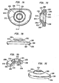
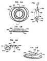
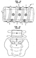
- FIGs. 13-14 in which a side perspective view of an intervertebral body cage and an anterior perspective view of a post implantation spinal column are shown, respectively, a more complete description of these devices of the prior art is herein provided.
- These cages 1 generally comprise tubular metal body 2 having an external surface threading 3. They are inserted transverse to the axis of the spine 4, into preformed cylindrical holes at the junction of adjacent vertebral bodies (in Figure 14 the pair of cages 1 are inserted between the fifth lumbar vertebra (L5) and the top of the sacrum (S1)).
- Two cages 1 are generally inserted side by side with the external threading 4 tapping into the lower surface of the vertebral bone above (L5), and the upper surface of the vertebral bone (S1) below.
- the cages 1 include holes 5 through which the adjacent bones are to grow. Additional materials, for example autogenous bone graft materials, may be inserted into the hollow interior 6 of the cage 1 to incite or accelerate the growth of the bone into the cage. End caps (not shown) are often utilized to hold the bone graft material within the cage 1.
- an object of the invention to provide an intervertebral spacer that stabilizes the spine without promoting a bone fusion across the intervertebral space.
- an artificial intervertebral disc or intervertebral spacer device comprising a pair of support members (e.g., spaced apart baseplates), each with an outwardly facing surface.
- the baseplates are arranged in a substantially parallel planar alignment (or slightly offset relative to one another in accordance with proper lordotic angulation) with the outwardly facing surfaces facing away from one another.
- the baseplates are to mate with the vertebral bodies so as to not rotate relative thereto, but rather to permit the spinal segments to bend (and in some embodiments, axially compress) relative to one another in manners that mimic the natural motion of the spinal segment.
- This natural motion is permitted by the performance of a ball and socket joint disposed between the secured baseplates, and the securing of the baseplates to the vertebral bone is achieved through the use of a vertebral body contact element attached to the outwardly facing surface of each baseplate.
- Preferable vertebral body contact elements include, but are not limited to, one or more of the following: a convex mesh, a convex solid dome, and one or more spikes.
- the convex mesh is preferably secured at its perimeter to the outwardly facing surface of the respective baseplate. This can be accomplished in any effective manner, however, laser welding and plasma coating burying are two preferred methods when the mesh is comprised of metal. While domed in its initial undeflected conformation, the mesh deflects as necessary during insertion of the artificial disc between vertebral bodies, and, once the artificial disc is seated between the vertebral bodies, the mesh deforms as necessary under anatomical loads to reshape itself to the concave surface of the vertebral endplate.
- the mesh is deformably reshapeable under anatomical loads such that it conformably deflects against the concave surface to securably engage the vertebral body endplate.
- the mesh is convexly shaped and is secured at its perimeter to the baseplate, the mesh is biased away from the baseplate but moveable toward the plate (under a load overcoming the bias; such a load is present, for example, as an anatomical load in the intervertebral space) so that it will securably engage the vertebral body endplate when disposed in the intervertebral space.
- the convex mesh further provides an osteoconductive surface through which the bone may ultimately grow.
- the mesh preferably is comprised of titanium, but can also be formed from other metals and/or non-metals. Inasmuch as the mesh is domed, it does not restrict the angle at which the artificial disc can be implanted.
- the flexible dome is described herein preferably as a wire mesh, other meshed or solid flexible elements can also be used, including flexible elements comprised of non-metals and/or other metals. Further, the flexibility, deflectability and/or deformability need not be provided by a flexible material, but can additionally or alternatively be provided mechanically or by other means.
- the convex mesh attachment devices and methods described herein can be used not only with the artificial discs and artificial disc baseplates described or referred to herein, but also with other artificial discs and artificial disc baseplates, including, but not limited to, those currently known in the art. Therefore, the description of the mesh attachment devices and methods being used with the artificial discs and artificial disc baseplates described or referred to herein should not be construed as limiting the application and/or usefulness of the mesh attachment device.
- each baseplate further comprises a porous area, which at least extends in a ring around the lateral rim of each outwardly facing surface.
- the porous area may be, for example, a sprayed deposition layer, or an adhesive applied beaded metal layer, or another suitable porous coating known in the art.
- the porous ring permits the long-term ingrowth of vertebral bone into the baseplate, thus permanently securing the prosthesis within the intervertebral space.
- the porous layer may extend beneath the domed mesh as well, but is more importantly applied to the lateral rim of the outwardly facing surface of the baseplate that seats directly against the vertebral body.
- Some of the embodiments described herein uses two baseplates each having the above described convex mesh on its outwardly facing surface, while other embodiments use two baseplates each having a convex solid dome in combination with a plurality of spikes on the lateral rim of the outwardly facing surface of the baseplates. It should be understood, however, that the various attachments devices or methods described herein (as well as any other attachment devices or methods, such as, for example, keels) can be used individually or in combination in any permutation, without departing from the scope of the present invention.
- the ball and socket joint disposed between the baseplates permits rotation and angulation of the two baseplates relative to one another about a centroid of motion centrally located between the baseplates.
- the housing e.g., the second baseplate and/or the convex structure
- has a protrusion e.g., a hemispherical protrusion or a hemispherical head of a pin secured in a pin hole in the housing
- a protrusion e.g., a hemispherical protrusion or a hemispherical head of a pin secured in a pin hole in the housing
- the invention when assembled, the invention enable angulation and limited rotation of the baseplates relative to one another about a centroid of motion that remains centrally located between the baseplates (at the center of the sphere defined by the ball), similar to the centroid of motion in a healthy natural intervertebral disc that is limited in its rotation by surrounding body structures.
- a benefit of limiting the relative rotation of the baseplates is that relative rotation beyond a certain range in a healthy natural disc is neither needed nor desired, because, for example, excess strain can be placed on the facet joints or ligaments thereby.
- the construction also prevents translation and separation of the baseplates relative to one another during rotation and angulation.
- the invention is shown in Figs 10a-10t .
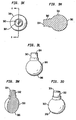
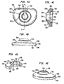
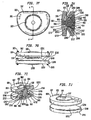
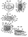
- Figs. 1a-c show top ( Fig. 1a ), side cutaway ( Fig. 1b ) and bottom ( Fig. 1 c) views of a first baseplate, the first baseplate having an inwardly directed radially compressible ball.
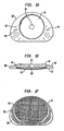
- Figs. 1d-f show top ( Fig. 1d ), side cutaway ( Fig. 1e ) and bottom ( Fig. 1f ) views of a second baseplate, the second baseplate having a circular recess within which seats a flexible convex structure.
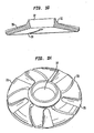
- Figs. 1g-h show side cutaway ( Fig. 1g ) and top perspective ( Fig. 1h ) views of a flexible convex structure, the flexible convex structure having spiral slots and radially extending grooves.
- Figs. 1i-j show exploded ( Fig. 1i ) and assembled ( Fig. 1j ) views of an exemplary intervertebral implant.
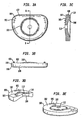
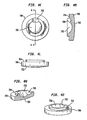
- Figs. 2a-c show top ( Fig. 2a ), side cutaway ( Fig. 2b ) and bottom ( Fig. 2c ) views of a first baseplate, the first baseplate having an inwardly directed radially compressible ball.
- Figs. 2d-f show top ( Fig. 2d ), side cutaway ( Fig. 2e ) and bottom ( Fig. 2f ) views of a second baseplate, the second baseplate having a curvate socket within which the ball is capturable for free rotation and angulation therein.
- Figs. 2g-h show exploded ( Fig. 2g ) and assembled ( Fig. 2h ) views of another exemplary intervertebral implant.
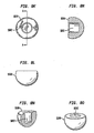
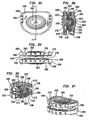
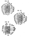
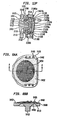
- Figs. 3a-e show top ( Fig. 3a ), side ( Fig. 3b ), side cutaway ( Fig. 3c ), perspective cutaway ( Fig. 3d ) and perspective ( Fig. 3e ) views of a first baseplate.
- Figs. 3f-j show top ( Fig. 3f ), side ( Fig. 3g ), side cutaway ( Fig. 3h ), perspective cutaway ( Fig. 3i ) and perspective ( Fig. 3j ) views of a first type of a second baseplate, the first type of second baseplate having a convex structure integrated therewith.
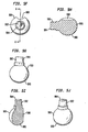
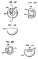
- Figs. 3k-o show top ( Fig. 3k ), side ( Fig. 3l ), side cutaway ( Fig. 3m ), perspective cutaway ( Fig. 3n ) and perspective ( Fig. 3o ) views of a first type of a ball.
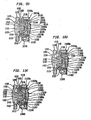
- Figs. 3p-t show top ( Fig. 3p ), side ( Fig. 3q ), side cutaway ( Fig. 3r ), perspective cutaway ( Fig. 3s ) and perspective ( Fig. 3t ) views of a first type of a cap.
- Figs. 3u-y show top ( Fig. 3u ), side ( Fig. 3v ), side cutaway ( Fig. 3w ), perspective cutaway ( Fig. 3x ) and perspective ( Fig. 3y ) views of an assembled exemplary intervertebral implant.
- Fig. 3z shows a side cutaway of an alternate assembled exemplary intervertebral implant, having a bifurcated cap housing a spring member.
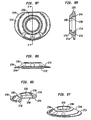
- Figs. 4a-e show top ( Fig. 4a ), side ( Fig. 4b ), side cutaway ( Fig. 4c ), perspective cutaway ( Fig. 4d ) and perspective ( Fig. 4e ) views of a second type of the second baseplate, the second type of the second baseplate having the convex structure integrated therewith and also having a curvate recess.
- Figs. 4f-j show top ( Fig. 4f ), side ( Fig. 4g ), side cutaway ( Fig. 4h ), perspective cutaway ( Fig. 4i ) and perspective ( Fig. 4j ) views of a second type of the ball, the second type of the ball having a protrusion.
- Figs. 4k-o show top ( Fig. 4k ), side ( Fig. 4l ), side cutaway ( Fig. 4m ), perspective cutaway ( Fig. 4n ) and perspective ( Fig. 4o ) views of a second type of a cap, the second type of cap having a curvate recess.
- Figs. 4p-t show top ( Fig. 4p ), side ( Fig. 4q ), side cutaway ( Fig. 4r ), perspective cutaway ( Fig. 4s ) and perspective ( Fig. 4t ) views of an assembled exemplary intervertebral implant.
- Fig. 4u shows a side cutaway of an alternate assembled exemplary intervertebral implant, having a bifurcated cap housing a spring member.
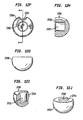
- Figs. 5a-e show top ( Fig. 5a ), side ( Fig. 5b ), side cutaway ( Fig. 5c ), perspective cutaway ( Fig. 5d ) and perspective ( Fig. 5e ) views of a third type of the second baseplate, the third type of the second baseplate having the convex structure integrated therewith and also having a protrusion.
- Figs. 5f-j show top ( Fig. 5f ), side ( Fig. 5g ), side cutaway ( Fig. 5h ), perspective cutaway ( Fig. 5i ) and perspective ( Fig. 5j ) views of a third type of the ball, the third type of the ball having a curvate recess.
- Figs. 5k-o show top ( Fig. 5k ), side ( Fig. 5l ), side cutaway ( Fig. 5m ), perspective cutaway ( Fig. 5n ) and perspective ( Fig. 5o ) views of an assembled exemplary intervertebral implant.
- Fig. 5p shows a side cutaway of an alternate assembled intervertebral implant, having a bifurcated cap housing a spring member.
- Figs. 6a-e show top ( Fig. 6a ), side ( Fig. 6b ), side cutaway ( Fig. 6c ), perspective cutaway ( Fig. 6d ) and perspective ( Fig. 6e ) views of a fourth type of the second baseplate, the fourth type of the second baseplate having the convex structure integrated therewith and also having a pin through hole for housing a pin.
- Figs. 6f-j show top ( Fig. 6f ), side ( Fig. 6g ), side cutaway ( Fig. 6h ), perspective cutaway ( Fig. 6i ) and perspective ( Fig. 6j ) views of an assembled exemplary intervertebral implant.
- Fig. 6k shows a side cutaway of an alternate assembled exemplary intervertebral implant, having a bifurcated cap housing a spring member.
- Figs. 7a-e show top ( Fig. 7a ), side ( Fig. 7b ), side cutaway ( Fig. 7c ), perspective cutaway ( Fig. 7d ) and perspective ( Fig. 7e ) views of a fifth type of the second baseplate, the fifth type of the second baseplate having the convex structure integrated therewith and also having a recess.
- Figs. 7f-j show top ( Fig. 7f ), side ( Fig. 7g ), side cutaway ( Fig. 7h ), perspective cutaway ( Fig. 7i ) and perspective ( Fig. 7j ) views of an assembled exemplary intervertebral implant.
- Fig. 7k shows a side cutaway of an alternate assembled exemplary intervertebral implant, having a bifurcated cap housing a spring member.
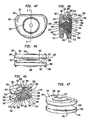
- Figs. 8a-e show top ( Fig. 8a ), side ( Fig. 8b ), side cutaway ( Fig. 8c ), perspective cutaway ( Fig. 8d ) and perspective ( Fig. 8e ) views of a first baseplate.
- Figs. 8f-j show top ( Fig. 8f ), side ( Fig. 8g ), side cutaway ( Fig. 8h ), perspective cutaway ( Fig. 8l ) and perspective ( Fig. 8j ) views of a first type of second baseplate, the first type of the second baseplate having a central curvate pocket of the fourth embodiment family.
- Figs. 8k-o show top ( Fig. 8k ), side ( Fig. 8l ), side cutaway ( Fig. 8m ), perspective cutaway ( Fig. 8n ) and perspective ( Fig. 8o ) views of a first type of a ball.
- Figs. 8p-t show top ( Fig. 8p ), side ( Fig. 8q ), side cutaway ( Fig. 8r ), perspective cutaway ( Fig. 8s ) and perspective ( Fig. 8t ) views of a first type of a convex structure.
- Figs. 8u-y show top ( Fig. 8u ), side ( Fig. 8v ), side cutaway ( Fig. 8w ), perspective cutaway ( Fig. 8x ) and perspective ( Fig. 8y ) views of an assembled exemplary intervertebral implant.
- Fig. 8z shows a side cutaway of an alternate assembled exemplary intervertebral implant, having a bifurcated second baseplate housing a spring member.
- Figs. 8aa-8bb show top ( Fig. 8aa ) and side cutaway ( Fig. 8bb ) views of an alternate first baseplate 9400.
- Figs. 8cc-8dd show top ( Fig. 8cc ) and side cutaway ( Fig. 8dd ) views of an alternate second baseplate 9500.
- Figs. 9a-e show top ( Fig. 9a ), side ( Fig. 9b ), side cutaway ( Fig. 9c ), perspective cutaway ( Fig. 9d ) and perspective ( Fig. 9e ) views of a second type of second baseplate, the second type of the second baseplate having the central curvate pocket and also having a curvate recess.
- Figs. 9f-j show top ( Fig. 9f ), side ( Fig. 9g ), side cutaway ( Fig. 9h ), perspective cutaway ( Fig. 9i ) and perspective ( Fig. 9j ) views of a second type of the ball, the second type of the ball having a protrusion.
- Figs. 9k-o show top ( Fig. 9k ), side ( Fig. 9l ), side cutaway ( Fig. 9m ), perspective cutaway ( Fig. 9n ) and perspective ( Fig. 9o ) views of a second type of the convex structure, the second type of the convex structure having a curvate recess.
- Figs. 9p-t show top ( Fig. 9p ), side ( Fig. 9q ), side cutaway ( Fig. 9r ), perspective cutaway ( Fig. 9s ) and perspective ( Fig. 9t ) views of an assembled exemplary intervertebral implant.
- Fig. 9u shows a side cutaway of an alternate assembled exemplary intervertebral implant, having a bifurcated second baseplate housing a spring member.
- Figs. 10a-e show top ( Fig. 10a ), side ( Fig. 10b ), side cutaway ( Fig. 10c ), perspective cutaway ( Fig. 10d ) and perspective ( Fig. 10e ) views of a third type of second baseplate according to the invention, the third type of the second baseplate having the central curvate pocket and also having a recess on a circumferential wall around the curvate pocket.
- Figs. 10f-j show top ( Fig. 10f ), side ( Fig. 10g ), side cutaway ( Fig. 10h ), perspective cutaway ( Fig. 10i ) and perspective ( Fig. 10j ) views of a third type of the ball according to the invention, the third type of the ball having a curvate recess.
- Figs. 10k-o show top ( Fig. 10k ), side ( Fig. 10l ), side cutaway ( Fig. 10m ), perspective cutaway ( Fig. 10n ) and perspective ( Fig. 10o ) views of a third type of the convex structure according to the invention, the third type of the convex structure having a protrusion.
- Figs. 10p-t show top ( Fig. 10p ), side ( Fig. 10q ), side cutaway ( Fig. 10r ), perspective cutaway ( Fig. 10s ) and perspective ( Fig. 10t ) views of an assembled preferred embodiment.
- Fig. 10u shows a side cutaway of an alternate assembled preferred embodiment, having a bifurcated second baseplate housing a spring member.
- Figs. 11a-e show top ( Fig. 11 a) , side ( Fig. 11 b) , side cutaway ( Fig. 11c ), perspective cutaway ( Fig. 11 d) and perspective ( Fig. 11e ) views of a fourth type of the convex structure, the fourth type of the convex structure having a pin through hole for housing a pin.
- Figs. 11f-j show top ( Fig. 11f ), side ( Fig. 11g ), side cutaway ( Fig. 11h ), perspective cutaway ( Fig. 11i ) and perspective ( Fig. 11j ) views of an assembled exemplary intervertebral implant.
- Fig. 11k shows a side cutaway of an alternate assembled exemplary intervertebral implant, having a bifurcated second baseplate housing a spring member.
- Figs. 12a-e show top ( Fig. 12a ), side ( Fig. 12b ), side cutaway ( Fig. 12c ), perspective cutaway ( Fig. 12d ) and perspective ( Fig. 12e ) views of a fifth type of the convex structure, the fifth type of the convex structure having a recess adjacent a curvate taper.
- Figs.12f-j show top ( Fig. 12f ), side ( Fig. 12g ), side cutaway ( Fig. 12h ), perspective cutaway ( Fig. 12l ) and perspective ( Fig. 12j ) views of fourth type of ball, the fourth type of ball having a curvate recess.
- Figs. 12k-o show top ( Fig. 12k ), side ( Fig. 12l ), side cutaway ( Fig. 12m ), perspective cutaway ( Fig. 12n ) and perspective ( Fig. 12o ) views of an assembled exemplary intervertebral implant.
- Fig. 12p shows a side cutaway of an alternate assembled intervertebral implant, having a bifurcated second baseplate housing a spring member.
- Fig. 13 shows a side perspective view of a prior art interbody fusion device.
- Fig. 14 shows a front view of the anterior portion of the lumbo-sacral region of a human spine, into which a pair of interbody fusion devices of Fig. 13 have been implanted.
- a first baseplate 10 is shown in top ( Fig. 1a ), side cutaway ( Fig. 1b ) and bottom ( Fig. 1c ) views.
- a second baseplate 30 is shown in top ( Fig. 1d ), side cutaway ( Fig. 1e ) and bottom ( Fig. 1f ) views.
- each baseplate 10,30 has an outwardly facing surface 12,32. Because the artificial disc of the invention is to be positioned between the facing surfaces of adjacent vertebral bodies, the two baseplates 10,30 used in the artificial disc are disposed such that the outwardly facing surfaces 12,32 face away from one another (as best seen in exploded view in Fig. 1g and in assembly view in Fig. 1h ).
- the two baseplates 10,30 are to mate with the vertebral bodies so as to not rotate relative thereto, but rather to permit the spinal segments to bend relative to one another in manners that mimic the natural motion of the spinal segment. This motion is permitted by the performance of a ball and socket joint disposed between the secured baseplates 10,30. The mating of the baseplates 10,30 to the vertebral bodies and the construction of the ball and socket joint are described below.
- each baseplate 10,30 is a flat plate preferably made of a metal such as, for example, cobalt-chromium or titanium) having an overall shape that conforms to the overall shape of the respective endplate of the vertebral body with which it is to mate.
- each baseplate 10,30 comprises a vertebral body contact element (e.g., a convex mesh 14,34, preferably oval in shape) that is attached to the outwardly facing surface 12,32 of the baseplate 10,30 to provide a vertebral body contact surface.
- the mesh 14,34 is secured at its perimeter to the outwardly facing surface 12,32 of the baseplate 10,30.
- the mesh 14,34 is domed in its initial undeflected conformation, but deflects as necessary during insertion of the artificial disc between vertebral bodies, and, once the artificial disc is seated between the vertebral bodies, deforms as necessary under anatomical loads to reshape itself to the concave surface of the vertebral endplate. This affords the baseplate 10,30 having the mesh 14,34 substantially superior gripping and holding strength upon initial implantation as compared with other artificial disc products.
- the mesh 14,34 further provides an osteoconductive surface through which the bone may ultimately grow.
- the mesh 14,34 is preferably comprised of titanium, but can also be formed from other metals and/or non-metals without departing from the scope of the invention.
- Each baseplate 10,30 further comprises at least a lateral ring 16,36 that is osteoconductive, which may be, for example, a sprayed deposition layer, or an adhesive applied beaded metal layer, or another suitable porous coating.
- This porous ring 16,36 permits the long-term ingrowth of vertebral bone into the baseplate 10,30, thus permanently securing the prosthesis within the intervertebral space. It shall be understood that this porous layer 18,36 may extend beneath the domed mesh 14,34 as well, but is more importantly applied to the lateral rim of the outwardly facing surface 12,32 of the baseplate 10,30 that seats directly against the vertebral body.
- the convex structure is configured as a flexible element and functions as a spring element the provides axial cushioning to the device.
- the convex structure has the socket of the ball and socket joint at its peak. In order to permit the flexible convex structure to flex under compressive loads applied to the device, it is a separate element from the second baseplate.
- the flexible convex structure is a belleville washer that has a frusto-conical shape.
- Other flexible convex structures are also contemplated as being suitable, such as, for example, convex structures that flex because of the resilience of the material from which they are made, because of the shape into which they are formed, and/or or because of the mechanical interaction between sub-elements of an assembly forming the convex structure.
- the convex structure is a separate element from the second baseplate in this embodiment family (so that it is able to flex), it is preferably maintained near the second baseplate so that the device does not separate in tension. Therefore, an extension of the second baseplate is provided (in the form of a shield element) to cover enough of the convex structure to so maintain it.
- the shield is a separate element from the second baseplate to ease manufacturing (during assembly, the flexible convex structure is first placed against the second baseplate, and then the shield is placed over the convex structure and secured to the second baseplate so that the convex structure is maintained between the second baseplate and the shield), but once the device is assembled, the second baseplate and the shield are effectively one element. That is, the second baseplate and shield can be considered to be a single integral housing within which the separate flexible convex structure flexes, because but for the sake of achieving desirable manufacturing efficiencies, the second baseplate and shield would be one piece.
- the manner of capturing the ball in the socket is effected by the ball being selectively radially compressible. That is, the ball is radially compressed to fit into the socket and thereafter receives a deflection preventing element to prevent subsequent radial compression, so that the ball remains captured in the socket. A more detailed description of the preferred manner in which this is accomplished is described below. Because the socket is formed at the peak of the flexible convex structure discussed immediately above, the capturing of the ball in the socket in this manner allows the ball to remain securely held for rotation and angulation even though the socket moves upward and downward with the flexing of the convex structure.
- the second baseplate preferably includes an access hole that accommodates placement of the deflection preventing element, so that the same can be applied to the ball after the ball is fitted into the socket. Accordingly, the ball is maintained in the socket.
- each of the baseplates 10,30 comprises features that, in conjunction with other components described below, form the ball and socket joint.
- the first baseplate 10 includes an inwardly facing surface 18 that includes a perimeter region 20 and a ball 22 mounted to protrude from the inwardly facing surface 18.
- the ball 22 preferably has a semispherical shape defining a spherical contour.
- the ball 22 includes a series of slots 24 that render the ball 22 radially compressible and expandable in correspondence with a radial pressure (or a radial component of a pressure applied thereto and released therefrom).
- the ball 22 further includes an axial bore 26 that accepts a deflection preventing element (e.g., rivet, plug, dowel, or screw; a rivet 28 is used herein as an example) (shown in Figs. 1i-j ). (Alternatively, the axial bore can be threaded to accept a screw.)
- a deflection preventing element e.g., rivet, plug, dowel, or screw; a rivet 28 is used herein as an example
- the axial bore can be threaded to accept a screw.
- the ball 22 Prior to the insertion of the rivet 28, the ball 22 can deflect radially inward because the slots 24 will narrow under a radial pressure. The insertion of the rivet 28 eliminates the capacity for this deflection. Therefore, the ball 22, before receiving the rivet 28, can be compressed to pass into, and thereafter seat in, a central curvate socket of a convex structure (described below).
- the rivet 28 can be inserted into the axial bore 26 to ensure that the ball 22 remains held in the curvate socket
- an access hole is preferably provided in the second baseplate 30 so that the interior of the device may be readily accessed for inserting the rivet 28 into the axial bore 26, or for other purposes.
- the second baseplate 30 includes an inwardly facing surface 38 that includes a perimeter region 40 and a central circular recess 42 within which the wide end of the convex structure resides, and a pair of holes 44 through which rivets 46 (shown in Figs. 1g-h ) may be provided for securing a shield element 48 that is placed over the convex structure, which shield 48 thus serves as an extension of the second baseplate 30 (the shield 48 is more fully set forth below with and shown on Figs. 1i-j ).
- the convex structure 31 that resides in the circular recess 42 is shown in side cutaway ( Fig. 1g ) and top perspective ( Fig. 1h ) views.
- the convex structure 31 is frusto-conical and is flexible. Because the convex structure 31 is flexible, it functions as a force restoring element (e.g., a spring) that provides axial cushioning to the device, by deflecting under a compressive load and restoring when the load is relieved.
- the flexible convex structure 31 is preferably, as shown, a belleville washer that has a frusto-conical shape.
- the belleville washer 31 preferably, as shown, has spiral slots and radially extending grooves.
- the restoring force of the belleville washer 31 is proportional to the elastic properties of the material or materials from which it is made. It should be understood that belleville washers having the configuration shown can be used, but that belleville washers having other conformations, that is, without or without slots and/or grooves, and/or with other groove and slots configurations, including the same or different numbers of grooves and/or slots, can also be used with and are encompassed by the present invention.
- the belleville washer 31 comprises a series of spiral slots 33 formed therein.
- the slots 33 extend from the outer edge of the belleville washer 31, inward along arcs generally directed toward the center of the element.
- the slots 33 do not extend fully to the center of the element.
- the slots 33 extend anywhere from a quarter to three quarters of the overall radius of the washer 31, depending upon the requirements of the patient, and the anatomical requirements of the device.
- the belleville washer 31 further comprises a series of grooves 35 formed therein.
- the grooves 35 extend radially from the outer edge of the belleville washer 31 toward the center of the element.
- the width and depth of each groove 35 decreases along the length of the groove 35 from the outer edge of the washer 31 toward the center of the washer 31, such that the center of the washer 31 is flat, while the outer edge of the washer 31 has grooves of a maximum groove depth.
- each groove can be (1) increasing along the length of the groove from the outer edge of the washer toward the center of the washer, (2) uniform along the length of the groove from the outer edge of the washer toward the center of the washer, or (3) varied along the length of each groove from the outer edge of the washer toward the center of the washer, either randomly or according to a pattern.
- each groove is not formed similarly to one or more other grooves, but rather one or more grooves are formed in any of the above-mentioned fashions, while one or more other grooves are formed in another of the above-mentioned fashions or other fashions.
- any groove pattern can be implemented, including, but not limited to, at least one radially spaced concentric groove, including, but not limited to, at least one such groove having at least one dimension that varies along the length of the groove. Belleville washers having circumferential extents that radially vary in at least one dimension, are also contemplated by the present invention.
- the belleville washer 31 responds to a compressive load by deflecting compressively; the spiral slots and/or radial grooves cause the washer to further respond to the load by spreading as the slots and/or the grooves in the washer expand under the load.
- the spring therefore, provides a restoring force which is proportional to the elastic modulus of the material in a hoop stressed condition.
- the curvate socket is formed at the peak of the convex structure 31.
- the curvate socket 37 is provided inasmuch as the central opening of the belleville washer 31 is enlarged.
- This central opening includes a curvate volume 37 for receiving therein the ball 22 of the first baseplate 10.
- the curvate volume 37 has a substantially constant radius of curvature that is also substantially equivalent to the radius of the ball 22.
- the spiral slots 33 of the washer 31 do not extend all the way to the central opening, and approach the opening only as far as the material strength of the washer 31 can handle without plastically deforming under the expected anatomical loading.
- each groove 35 of the washer 31 decreases along the length of the groove 35 from the outer edge of the washer 31 toward the center of the washer 31, such that the center of the washer 31 is flat, while the outer edge of the washer 31 has grooves of a maximum groove depth. Therefore, the central opening can be formed from flat edges. It should be understood that this is not required, but rather is preferred.
- the curvate socket 37 has an opening diameter that accommodates passage therethrough of the ball 22 in a radially compressed state (but not in an uncompressed state), and a larger inner diameter that accommodates the ball 22 in the uncompressed state. Therefore, the ball 22 can be radially compressed to pass into the curvate socket 37 under force, and then will radially expand to the uncompressed state once in the curvate socket 37. Once the rivet 28 is then secured into the axial bore 26, the rivet 28 prevents the ball 22 from radially compressing, and therefore the ball 22 cannot back out through the opening.
- An access hole 39 in the second baseplate 30 below the curvate socket 37 has a diameter that accommodates the diameter of the rivet 28 and thereby provides easy access to insert the rivet 28 in the axial bore 26 after the ball 22 has been seated in the curvate socket 37.
- the diameter of the access hole 39 is smaller than the inner diameter of the curvate socket 37.
- the curvate socket 37 defines a spherical contour that closely accommodates the ball 22 for free rotation and angulation in its uncompressed state. Therefore, when seated in the curvate socket 37, the ball 22 can rotate and angulate freely relative to the curvate socket 37 through a range of angles, thus permitting the opposing baseplates 10,30 to rotate and angulate freely relative to one another through a corresponding range of angles equivalent to the fraction of normal human spine rotation and angulation (to mimic normal disc rotation and angulation).
- the perimeter regions 20,40 have corresponding contours, so that the meeting of the perimeter regions 20,40 as a result of the angulation of the baseplates 10,30 reduces any surface wearing.
- Figs. 1i-j exploded ( Fig. 1i ) and assembled ( Fig. 1i ) views of an examplary intervertebral implant. Included in these views are the shield 48 and the corresponding rivets 46. More particularly, assembly of the disc is preferably as follows.
- the first and second baseplates 10,30 are disposed so that their outwardly facing surfaces 12,32 face away from one another and their inwardly facing surfaces 18,38 are directed toward one another.
- the convex structure 31 is then positioned with its wide end in the circular recess 42 of the second baseplate, so that the curvate socket 37 of the convex structure 31 is aligned with the ball 22 of the first baseplate 10.
- the shield 48 is secured over the belleville washer 31 (the shield 48 is preferably frusto-conical to follow the shape of the belleville washer 31, although other shield shapes are suitable and contemplated) by passing the central hole 41 of the shield 48 over the curvate socket 37 and applying the rivets 46 through rivet holes 43 in the shield 48 and into the rivet holes 44 in the second baseplate 30. Then, the ball 22 is pressed into the curvate socket 37 under a force sufficient to narrow the slots 24 and thereby radially compress the ball 22 until the ball 22 fits through and passes through the opening of the curvate socket 37.
- the ball 22 will radially expand as the slots 24 widen until it has returned to its uncompressed state and the spherical contour defined by the ball 22 is closely accommodated by the spherical contour defined by the curvate socket 37 and the ball 22 can rotate and angulate freely relative to the curvate socket 37.
- the rivet 28 is passed through the access hole 39 and pressed into the axial bore 26 of the ball 22 to prevent any subsequent radially compression of the ball 22 and therefore any escape from the curvate socket 37 thereby.
- the baseplates 10,30 are rotatable relative to one another because the ball 22 rotates freely within the curvate socket 37, and angulatable relative to one another because the ball 22 angulates freely within the socket 37. Because the convex structure 31 is flexible (and is housed in the second baseplate 30 in a manner that permits it to flex), the baseplates 10,30 are also axially compressible relative to one another. Because the ball 22 is held within the curvate socket 37 by a rivet 28 in the axial bore 26 preventing radial compression of the ball 22, the artificial disc can withstand tension loading of the baseplates 10,30.
- the ball 22 in the curvate socket 37 seeks to radially compress to fit through the opening of the curvate socket 37.
- the rivet 28 in the axial bore 26 of the ball 22 prevents the radial compression, thereby preventing the ball 22 from exiting the curvate socket 37. Therefore, the assembly does not come apart under normally experienced tension loads. This ensures that no individual parts of the assembly will pop out or slip out from between the vertebral bodies when, e.g., the patient stretches or hangs while exercising or performing other activities.
- the disc assembly in combination with the securing of the baseplates 10,30 to the adjacent vertebral bones via the mesh domes 14,34, the disc assembly has an integrity similar to the tension-bearing integrity of a healthy natural intervertebral disc. Also, because the ball 22 is laterally captured in the curvate socket 37, lateral translation of the baseplates 10,30 relative to one another is prevented during rotation and angulation, similar to the performance of healthy natural intervertebral disc. Because the baseplates 10,30 are made angulatable relative to one another by the ball 22 being rotatably and angulatably coupled in the curvate socket 37, the disc assembly provides a centroid of motion within the ball 22. Accordingly, the centroid of motion of the disc assembly remains centrally located between the vertebral bodies, similar to the centroid of motion in a healthy natural intervertebral disc.
- a first baseplate 50 is shown in top ( Fig. 2a ), side cutaway ( Fig. 2b ) and bottom ( Fig. 2c ) views.
- a second baseplate 70 is shown in top ( Fig. 2d ), side cutaway ( Fig. 2e ) and bottom ( Fig. 2f ) views.
- the convex structure is configured as a non-flexible element that is integral with the second baseplate, and has the socket of the ball and socket joint at its peak. More clearly stated, the devices of this second embodiment family do not feature a flexible convex structure, and therefore (and also because of the manner in which the ball is captured in this second embodiment family, discussed immediately below) there is no need for the convex structure to be a separate element from the second baseplate.
- the convex structure has a frusto-conical shape.
- the manner of capturing the ball in the socket is identical to that shown in Figs. 1a-1j .
- first and second baseplates 50,70 are similar to the first and second baseplates 10,30 of the first embodiment family described above with regard to each outwardly facing surface 52,12 having a vertebral body contact element 54,74 and an adjacent osteoconductive ring 56,76, and each inwardly facing surface 58,78 having a perimeter region 60,80.
- the two baseplates 50,70 are joined with a ball and socket joint, and therefore each of the baseplates 50,70 comprises features that, in conjunction with other components described below, form the ball and socket joint.
- the first baseplate 50 is formed similarly to the first baseplate 10 of the first embodiment family, having a ball 62 mounted to protrude from the inwardly facing surface 58.
- the ball 62 preferably has a semispherical shape defining a spherical contour.
- the ball 62 is structurally and functionally identical to the ball 22, and as such is selectively radially compressible in the same manner as the ball 22 of the first embodiment family.
- the ball 62 is capturable in a curvate socket 77 formed at the peak of a convex structure 71 protruding from the second baseplate 70.
- the curvate socket 77 is functionally and structurally identical to the curvate socket 37.
- the convex structure 77 of the device rather than being a flexible separate element from the second baseplate as in the first embodiment family, is integral with the second baseplate 70.
- the convex structure 77 is frusto-conical, but is not flexible, and therefore does not function as a force restoring element as does the flexible convex structure 37.
- Access to the convex structure 77 for providing easy access to insert the rivet 68 in the axial bore 66 of the ball 62 after the ball 62 has been seated in the curvate socket 77 is provided by an access hole 79 in the second baseplate 70 below and leading to the curvate socket 77.
- the access hole 79 is otherwise structurally identical to the access hole 39 in the second baseplate 30.
- FIG. 2g-h an assembled examplary intervertebral implant is shown in exploded ( Fig. 2g ) and assembled ( Fig. 2h ) views. More particularly, assembly of the disc is preferably as follows.
- the first and second baseplates 50,70 are disposed so that their outwardly facing surfaces 52,72 face away from one another and their inwardly facing surfaces 58,78 are directed toward one another, and so that the ball 62 of the first baseplate 50 is aligned with the curvate socket 77 of the convex structure 71 of the second baseplate 70.
- the ball 62 is pressed into the curvate socket 77 under a force sufficient to narrow the slots 64 and thereby radially compress the ball 62 until the ball 62 fits through and passes through the opening of the curvate socket 77.
- the ball 62 will radially expand as the slots 64 widen until it has returned to its uncompressed state and the spherical contour defined by the ball 62 is closely accommodated by the spherical contour defined by the curvate socket 77 and the ball 62 can rotate and angulate freely relative to the curvate socket 77.
- the rivet 68 is passed through the access hole 79 and pressed into the axial bore 66 of the ball 62 to prevent any subsequent radially compression of the ball 62 and therefore any escape from the curvate socket 77 thereby.
- the baseplates 50,70 are rotatable relative to one another because the ball 62 rotates freely within the curvate socket 77, and angulatable relative to one another because the ball 62 angulates freely within the socket 77. Because the ball 62 is held within the curvate socket 77 by a rivet 68 in the axial bore 66 preventing radial compression of the ball 62, the artificial disc can withstand tension loading of the baseplates 50,70. More particularly, when a tension load is applied to the baseplates 50,70, the ball 62 in the curvate socket 77 seeks to radially compress to fit through the opening of the curvate socket 77.
- the rivet 68 in the axial bore 66 of the ball 62 prevents the radial compression, thereby preventing the ball 62 from exiting the curvate socket 77. Therefore, the assembly does not come apart under normally experienced tension loads. This ensures that no individual parts of the assembly will pop out or slip out from between the vertebral bodies when, e.g., the patient stretches or hangs while exercising or performing other activities.
- the disc assembly in combination with the securing of the baseplates 50,70 to the adjacent vertebral bones via the mesh domes 54,74, the disc assembly has an integrity similar to the tension-bearing integrity of a healthy natural intervertebral disc.
- the ball 62 is laterally captured in the curvate socket 77, lateral translation of the baseplates 50,70 relative to one another is prevented during rotation and angulation, similar to the performance of healthy natural intervertebral disc.
- the baseplates 50,70 are made angulatable relative to one another by the ball 62 being rotatably and angulatably coupled in the curvate socket 77, the disc assembly provides a centroid of motion within the ball 62. Accordingly, the centroid of motion of the disc assembly remains centrally located between the vertebral bodies, similar to the centroid of motion in a healthy natural intervertebral disc.
- the convex structure is configured as a non-flexible element that is integral with the second baseplate, and has the socket of the ball and socket joint at its peak, similar to the configuration of the convex structure above.
- the convex structure is shaped to have a curved taper.
- the access hole in the second baseplate has a diameter that accommodates the diameter of the ball, and leads to the interior of the peak, which interior is formed as a concavity having an opening diameter that accommodates the diameter of the ball.
- the concavity has a curvature closely accommodating the contour of the ball, and the concavity is either hemispherical or less-than-hemispherical so that the ball can easily be placed into it.
- an extension of the second baseplate in the form of a cap element
- the cap has an interior face that preferably has a concavity (that has a curvature that closely accommodates the contour of the ball) to complete the socket.
- the peak of the convex structure has a bore that accommodates a post to which the ball and the first baseplate are attached (one to each end of the post), but does not accommodate the ball for passage through the bore. Accordingly, the ball is maintained in the socket.
- a first baseplate 100 is shown in top ( Fig. 3a ), side ( Fig. 3b ), side cutaway ( Fig. 3c ), perspective cutaway ( Fig. 3d ) and perspective ( Fig. 3e ) views.
- a first type 200 of a second baseplate is shown in top ( Fig. 3f ), side ( Fig. 3g ), side cutaway ( Fig. 3h ), perspective cutaway ( Fig. 3i ) and perspective ( Fig. 3j ) views.
- first and second baseplates 100,200 are similar to the first and second baseplates 50,70 described above with regard to each having an outwardly facing surface 102,202, and each inwardly facing surface 108,208 having a perimeter region 110,210, all of which elements are, for example, identical to the corresponding elements as described above.
- each of the first and second baseplates 100,200 instead of having a convex mesh as a vertebral body contact element, have a convex solid dome 103,203 and a plurality of spikes 105,205 as vertebral body contact element.
- the dome 103,203 is covered with an osteoconductive layer of a type known in the art.
- the convex solid dome 203 of the second baseplate 200 is provided by the cap element (described below) that serves as an extension of the second baseplate 200 to capture the ball (described below), as best shown in Figs. 3u-y .
- the convex mesh is suitable for use with these other vertebral body contact elements, and can be attached over the convex dome 103,203 by laser welding, or more preferably, by plasma burying (where the perimeter region of the convex mesh is buried under a plasma coating, which coating secures to the outwardly facing surface of the baseplate to which it is applied, and thus secures the convex mesh to the outwardly facing surface).
- each of the baseplates 100,200 comprises features that, in conjunction with other components described below, form the ball and socket joint.
- the ball and socket joint includes a solid ball (described below) mounted to protrude from the inwardly facing surface 108 of the first baseplate 100, and a curvate socket formed at a peak of a non-flexible convex structure (described below) that is integral with the second baseplate 200, within which curvate socket the ball is capturable for free rotation and angulation therein. As shown in Figs.
- the mounting for the ball includes a central hole 112 on the inwardly facing surface 108 of the first baseplate 100, which hole 112 accepts a tail end of a post (described below) that has the ball at a head end of the post.
- the tail end compression locks into the hole 112.
- the convex structure 201 is integral with the second baseplate 200 and includes a curvate pocket 212 formed by a central portion of the inwardly facing surface 209 of the convex structure 201 convexing inwardly and by a central portion of an outwardly facing surface 213 of the convex structure 201 concaving inwardly.
- the pocket 212 has a semispherical contour on the central portion of the outwardly facing surface 213 and an apex at the center of the semispherical contour.
- the convex structure 201 has a bore 214 through the apex of the pocket 212, to accommodate the post.
- the second baseplate 200 has on its outwardly facing surface 202 an access hole 209 surrounded by a circular recess 216 leading to the pocket 212, which recess 216 accepts the cap (described below) that serves as an extension of the second baseplate 200.
- a first type 300 of the ball is shown in top ( Fig. 3k ), side ( Fig. 3l ), side cutaway ( Fig. 3m ), perspective cutaway ( Fig. 3n ) and perspective ( Fig. 3o ) views.
- the ball 300 is mounted at a head end 306 of a post 302 that also has a tail end 304.
- the ball 300 defines a spherical contour that is interrupted by the shaft of the post 302.
- a first type 400 of the cap is shown in top ( Fig. 3p ), side ( Fig. 3q ), side cutaway ( Fig. 3r ), perspective cutaway ( Fig. 3s ) and perspective ( Fig. 3t ) views.
- the cap 400 includes an outwardly facing surface 402 that complements the outwardly facing surface 202 of the second baseplate 200 when the cap 400 is secured in the circular recess 216 of the second baseplate 200 (preferably, as shown, the outwardly facing surface 402 of the cap 400 provides the second baseplate 200 with the convex dome 203, as best shown in Figs. 3u-y ).
- the cap 400 further includes an inwardly facing surface 404, and a curvate pocket 406 formed by a central portion of the inwardly facing surface 404 of the cap 400 concaving outwardly.
- the pocket 406 has a semispherical contour that closely accommodates the spherical contour defined by the ball 300.
- the semispherical contour of the pocket 406 of the cap 400 opposes the semispherical contour of the pocket 212 of the convex structure 201 such that when the cap 400 is secured in the circular recess 216 of the second baseplate 200, the semispherical contours together define a socket 207 defining a spherical contour that closely accommodates the spherical contour defined by the ball 300 for free rotation and angulation of the ball 300 in the pockets 406,212.
- Each of the semispherical contour of the pocket 406 and the semispherical contour of the pocket 212 are preferably no greater than hemispherical, to make easier the assembly of the device.
- assembly of the disc is preferably as follows.
- the tail end 304 of the post 302 is passed through the access hole 209 in the second baseplate 200 and through the bore 214 at the apex of the curvate pocket 212 of the convex structure 201, and the tail end 304 is thereafter secured to the central hole 112 in the first baseplate 100.
- the access hole 209 has a diameter that accommodates the diameter of the ball 300 at the head 306 of the post 302, and the curvate pocket 212 on the outwardly facing surface 213 of the convex structure 201 has an opening diameter that accommodates the ball 300 for seating in the pocket 212 when the tail end 304 is fully passed through the bore 214.
- the bore 214 at the apex of the curvate pocket 212 has a diameter greater than the diameter of the post 302 but smaller than the diameter of the ball 300 at the head 306 of the post 302.
- the post 302 fits through the bore 214, but the ball 300 does not, and the convex structure 201 (and the second baseplate 200) cannot be freed from the ball 300 once the tail end 304 of the post 302 is secured to the first baseplate 100.
- the attachment of the tail end 304 of the post 302 is preferably accomplished by compression locking (if accomplished alternatively or additional by laser welding, the laser weld can, e.g., be applied from the outwardly facing surface 102 of the first baseplate 100 if the hole 112 passes completely through the first baseplate 100).
- the tail end 304 can also alternatively or additionally be threaded into the central hole 112 for increased stability of the attachment.
- the semispherical contour of the pocket 212 closely accommodates the spherical contour defined by the ball 300, so that the ball 300 can freely rotate in the pocket 212 about the longitudinal axis of the post 302, and can freely angulate in the pocket 212 about a centroid of motion located at the center of the ball 300.
- the bore 214 is tapered to a larger diameter toward the first baseplate 100, to permit the post 302 to angulate (about the centroid of motion at the center of the ball 300) with respect to the bore 214 as the ball 300 angulates in the pocket 212.
- the conformation of the taper accommodates angulation of the post 302 at least until the perimeter regions 110,210 of the inwardly facing surfaces 108,208/211 meet.
- the cap 400 is secured in the circular recess 216 of the second baseplate 200, so that the curvate pocket 406 of the cap 400 and the opposing curvate pocket 212 of the convex structure 201 together form the socket 207 defining the spherical contour within which the ball 300 at the head 306 of the post 302 freely rotates and angulates as described above.
- the application of the cap 400 also seals the access hole 209 in the second baseplate (or, if the cap 400 has a bore, it preferably reduces the diameter of the access hole 209 to a size that does not accommodate the diameter of the ball 300).
- the cap 400 preferably is secured in the circular recess 216 by compression locking (a laser weld can alternatively or additionally be used, or other suitable attachment means).
- the cap 400 preferably has an outwardly facing surface 402 that complements the outwardly facing surface 202 of the second baseplate 200 for surface uniformity once the cap 400 is secured.
- the cap 400 may also additionally or alternatively be threaded into the circular recess 216 for increased stability of the attachment.
- FIG. 3z an assembled alternate intervertebral implant is shown in side cutaway view.
- This one incorporates a multi-part cap (with first part 4000a and-second part 4000b) housing a spring member 4100 that provides axial compressibility, such that a compressive load applied to the baseplates is borne by the spring member 4100.
- Elements of this implant that are also elements found in the above described implants are like numbered, and the assembly is identical to that above, with some differences due to the incorporation of the spring member 4100.
- the cap features are numbered in the 4000's rather than the 400's.
- assembly of the disc is preferably as follows.
- the tail end 304 of the post 302 is passed through the access hole 209 in the second baseplate 200 and through the bore 214 at the apex of the curvate pocket 212 of the convex structure 201, and the tail end 304 is thereafter secured to the central hole 112 in the first baseplate 100.
- the access hole 209 has a diameter that accommodates the diameter of the ball 300 at the head 306 of the post 302, and the curvate pocket 212 on the outwardly facing surface 213 of the convex structure 201 has an opening diameter that accommodates the ball 300 for seating in the pocket 212 when the tail end 304 is fully passed through the bore 214.
- the ball 300 can be placed through the access hole 209 and into the curvate pocket during this step.
- the bore 214 at the apex of the curvate pocket 212 has a diameter greater than the diameter of the post 302 but smaller than the diameter of the ball 300 at the head 306 of the post 302. Therefore, as the ball 300 is being placed into the curvate pocket 212, the post 302 fits through the bore 214, but the ball 300 does not, and the convex structure 201 (and the second baseplate 200) cannot be freed from the ball 300 once the tail end 304 of the post 302 is secured to the first baseplate 100.
- the attachment of the tail end 304 of the post 302 is preferably accomplished by compression locking (if accomplished alternatively or additionally by laser welding, the laser weld can, e.g., be applied from the outwardly facing surface 102 of the first baseplate 100 if the hole 112 passes completely through the first baseplate 100).
- the tail end 304 can also alternatively or additionally be threaded into the central hole 112 for increased stability of the attachment.
- the semispherical contour of the pocket 212 closely accommodates the spherical contour defined by the ball 300, so that the ball 300 can freely rotate in the pocket 212 about the longitudinal axis of the post 302, and can freely angulate in the pocket 212 about a centroid of motion located at the center of the ball 300.
- the bore 214 is tapered to a larger diameter toward the first baseplate 100, to permit the post 302 to angulate (about the centroid of motion at the center of the ball 300) with respect to the bore 214 as the ball 300 angulates in the pocket 212.
- the conformation of the taper accommodates angulation of the post 302 at least until the perimeter regions 110,210 of the inwardly facing surfaces 108,208/211 meet.
- the second part 4000b of the multi-part cap is secured in the circular recess 216 of the second baseplate 200, so that the curvate pocket 4060 of the inwardly facing surface 4040b of the cap second part 4000b and the opposing curvate pocket 212 of the convex structure 201 together form the socket 207 defining the spherical contour within which the ball 300 at the head 306 of the post 302 freely rotates and angulates as described above.
- the application of the cap second part 4000b also seals the access hole 209 in the second baseplate (or, if the cap second and first parts 4000b, 4000a have bores, it preferably reduces the diameter of the access hole 209 to a size that does not accommodate the diameter of the ball 300).
- the cap second part 4000b is preferably not compressed into, but rather fits loosely within the boundaries of, the circular recess 216, so that when the first baseplate 100 is compressed toward the second baseplate 200, the cap second part 4000b may travel toward the cap first part 4000a as the spring member 4100 compresses (due to the cap first part 4000a being secured in the circular recess 216 to the second baseplate 200).
- a spring member providing shock absorption preferably includes an elastomeric material, such as, for example, polyurethane or silicon
- a spring member providing shock dampening preferably includes a plastic material, such as, for example, polyethylene. It should be understood that metal springs may alternatively or additionally be used.
- the illustrated spring member 4100 is formed of an elastomeric material, for example.
- the illustrated spring member 4100 is ring-shaped, for example, such that it fits just inside the circumferential edge of the outwardly facing surface 4020b of the cap second part 4000b as shown.
- the cap first part 4000a is secured in the circular recess 216 of the second baseplate 200 to incarcerate the cap second part 4000b, and the spring member 4100 between the outwardly facing surface 4020b of the cap second part 4000b and the inwardly facing surface 4040a of the cap first part 4000a.
- the cap first part 4000a preferably is secured in the circular recess 216 by compression locking (a laser weld can alternatively or additionally be used, or other suitable attachment means).
- the cap second part 4000b should be dimensioned such that, and the spring member 4100 should have an uncompressed height such that, a gap is present between the outwardly facing surface 4020b of the cap second part 4000b and the inwardly facing surface 4040a of the cap first part 4000a when the disc is assembled.
- the gap preferably has a height equivalent to the anticipated distance that the spring member 4100 will compress under an anticipated load.
- the cap first part 4000a preferably has an outwardly facing surface 4020a that complements the outwardly facing surface 202 of the second baseplate 200 for surface uniformity once the cap first part 4000a is secured.
- the cap first part 4000a may also additionally or alternatively be threaded into the circular recess 216 for increased stability of the attachment Accordingly, part or all of a compressive load applied to the baseplates will be borne by the spring member 4100, which will dampen the load and/or absorb the load and preferably help return the baseplates to their original uncompressed relative positions.
- the baseplates are rotatable relative to one another because the ball 300 rotates freely within the socket 207, and angulatable relative to one another because the ball 300 angulates freely within the socket 207.
- the artificial disc can withstand tension loading of the baseplates 100,200. More particularly, when a tension load is applied to the baseplates 100,200 the ball 300 seeks to pass through the bore 214 at the apex of the curvate pocket 212.
- the disc assembly in combination with the securing of the baseplates 100,200 to the adjacent vertebral bones via the domes 103,203 and spikes 105,205, the disc assembly has an integrity similar to the tension-bearing integrity of a healthy natural intervertebral disc.
- the ball 300 is laterally captured in the socket 207, lateral translation of the baseplates 100,200 relative to one another is prevented during rotation and angulation, similar to the performance of healthy natural intervertebral disc.
- the baseplates 100,200 are made angulatable relative to one another by the ball 300 being rotatably and angulatably coupled in the socket 207, the disc assembly provides a centroid of motion within the ball 300. Accordingly, the centroid of motion of the disc assembly remains centrally located between the vertebral bodies, similar to the centroid of motion in a healthy natural intervertebral disc.
- the remaining implants limit the rotation (but preferably not the angulation) of the ball in the socket defined by the pocket of the convex structure and the pocket of the cap.
- Each implant accomplishes this in a different manner, but each one utilizes interference between a protrusion and a recess to limit the rotation.
- the protrusion is preferably hemispherical, and the recess preferably has a semicylindrical contour within which the protrusion fits.
- the protrusion is preferably hemispherical, and the recess preferably has a curvate contour that is not semicylindrical.
- the recess has a curvate contour that is not semicylindrical so that it optimally interacts with the protrusion in that embodiment.
- the boundaries of the recess define the limits of rotation of the ball within the socket, by allowing movement of the protrusion relative to the recess as the ball rotates through a certain range in the socket, but providing interference with the protrusion to prevent rotation of the ball beyond that range in the socket.
- the recess has a depth equivalent to the radius of the protrusion, but a radius of curvature greater than that of the protrusion.
- the boundaries of the recess preferably do not limit the angulation of the ball within the socket, at least until the perimeter regions of the inwardly facing surfaces meet.
- the recess has a length greater than the range of movement of the protrusion relative to the recess as the ball angulates in the socket
- the discs when assembled, the discs enable angulation and limited rotation of the baseplates relative to one another about a centroid of motion that remains centrally located between the baseplates (at the center of the sphere defined by the ball), similar to the centroid of motion in a healthy natural intervertebral disc that is limited in its rotation by surrounding body structures.
- a benefit of limiting the relative rotation of the baseplates is that relative rotation beyond a certain range in a healthy natural disc is neither needed nor desired, because, for example, excess strain can be placed on the facet joints or ligaments thereby.
- the construction also prevents translation and separation of the baseplates relative to one another during rotation and angulation.
- each of the remaining implants forms the protrusion and corresponding recess in a different manner, utilizing components that are either identical or similar to the components above, and some embodiments utilize additional components.
- Other implants will now be described in greater detail.
- a hemispherical protrusion is formed on the ball itself, and interacts in the above-described manner with a curvate recess formed adjacent the socket defined by the pocket of the convex structure and the pocket of the cap. More particularly, this implant uses the same first baseplate 100 as described above. Referring to Figs. 4a-e , a second type 500 of second baseplate is shown in top ( Fig. 4a ), side ( Fig. 4b ), side cutaway ( Fig. 4c ), perspective cutaway ( Fig. 4d ) and perspective ( Fig. 4e ) views.
- This second type 500 of second baseplate is identical to the first type 200 of second baseplate described above (and thus similar features are reference numbered similar to those of the first type 200 of second baseplate, but in the 500s rather than the 200s), except that this second type 500 of second baseplate has a curvate recess 518 adjacent the curvate pocket 512 in the convex structure 501.
- a second type 600 of ball is shown in top ( Fig. 4f ), side ( Fig. 4g ), side cutaway ( Fig. 4h ), perspective cutaway ( Fig. 4i ) and perspective ( Fig. 4j ) views.
- the ball 600 is identical to the first type 300 of ball described above (and thus similar features are reference numbered similar to those of the first type 300 of ball, but in the 600s rather than the 300s), except that the spherical contour defined by this second type 600 of ball is also interrupted by a hemispherical protrusion 608.
- a second type 700 of cap is shown in top ( Fig. 4k ), side ( Fig. 4l ), side cutaway ( Fig. 4m ), perspective cutaway ( Fig. 4n ) and perspective ( Fig. 4o ) views.
- This second type 700 of cap is identical to the first type 400 of cap described above (and thus similar features are reference numbered similar to those of the first type 400 of cap, but in the 700s rather than the 400s), except that this second type 700 of cap has a curvate recess 708 adjacent the curvate pocket 706.
- Figs. 4p-t an assembled implant is shown in top ( Fig. 4p ), side ( Fig. 4q ), side cutaway ( Fig. 4r ), perspective cutaway ( Fig. 4s ) and perspective ( Fig. 4t ) views.
- the curvate recesses 518,708 together form the recess described above in the discussion of the manner In which these remaining implants limit rotation of the ball in the socket, and that the protrusion 608 serves as the protrusion described above in the same discussion.
- the protrusion 608 and recesses 518,708 interact in the above described manner to limit the rotation of the ball 600 in the socket 507 defined by the curvate pockets 512,706.
- FIG. 4u an assembled alternate implant is shown in side cutaway view.
- This alternate implant incorporates a multi-part cap (with first part 7000a and second part 7000b) housing a spring member 7100 that provides axial compressibility, such that a compressive load applied to the baseplates is borne by the spring member 7100.
- Elements of this implant that are also elements found in the implants above are like numbered.
- the curvate recesses 518,7080 together form the recess described above, and the protrusion 608 serves as the protrusion described above, and thus the protrusion 608 and the recesses 518,7080 interact in the above described manner to limit the rotation of the ball 600 in the socket 507 defined by the curvate pockets 512,7060.
- Assembly of this alternate implant is identical to that above, except that the protrusion 608 is longitudinally aligned with the recess 518, and the recess 7080 is similarly aligned, so that when the cap second part 7000b is disposed in the circular recess 516 of the second baseplate 500, the protrusion 608 is fitted within the recesses 518,7080 for interaction as described above as the ball 600 rotates and angulates in the socket 507.
- the cap second part 7000b is preferably not compressed into, but rather fits loosely within, the circular recess 516, so that when the first baseplate 100 is compressed toward the second baseplate 500, the cap second part 7000b may travel toward the cap first part 7000a as the spring member 7100 compresses (due to the cap first part 7000a being secured in the circular recess 516 to the second baseplate 500). The spring member 7100 is then disposed on the outwardly facing surface 7020b of the cap second part 7000b.
- a spring member providing shock absorption preferably includes an elastomeric material, such as, for example, polyurethane or silicon, and a spring member providing shock dampening preferably includes a plastic material, such as, for example, polyethylene. It should be understood that metal springs may alternatively or additionally be used.
- the illustrated spring member 7100 is formed of an elastomeric material, for example.
- the illustrated spring member 7100 is ring-shaped, for example, such that it fits just inside the circumferential edge of the outwardly facing surface 7020b of the cap second part 7000b as shown.
- the cap first part 7000a is secured in the circular recess 516 of the second baseplate 500 to incarcerate the cap second part 7000b, and the spring member 7100 between the outwardly facing surface 7020b of the cap second part 7000b and the inwardly facing surface 7040a of the cap first part 7000a.
- the cap first part 7000a preferably is secured in the circular recess 516 by compression locking (a laser weld can alternatively or additionally be used, or other suitable attachment means).
- the cap second part 7000b should be dimensioned such that, and the spring member 7100 should have an uncompressed height such that, a gap is present between the outwardly facing surface 7020b of the cap second part 7000b and the inwardly facing surface 7040a of the cap first part 7000a when the disc is assembled.
- the gap preferably has a height equivalent to the anticipated distance that the spring member 7100 will compress under an anticipated load.
- the cap first part 7000a preferably has an outwardly facing surface 7020a that complements the outwardly facing surface 502 of the second baseplate 500 for surface uniformity once the cap first part 7000a is secured.
- the cap first part 7000a may also additionally or alternatively be threaded into the circular recess 516 for increased stability of the attachment. Accordingly, part or all of a compressive load applied to the baseplates will be borne by the spring member 7100, which will dampen the load and/or absorb the load and preferably help return the baseplates to their original uncompressed relative positions.
- a hemispherical protrusion is formed to protrude into the socket defined by the pocket of the convex structure and the pocket of the cap, and interacts in the above-described manner with a semicylindrical recess formed on the ball. More particularly, this implant uses the same first baseplate 100 and the same cap 400. Referring to Figs. 5a-e , a third type 800 of second baseplate is shown in top ( Fig. 5a ), side ( Fig. 5b ), side cutaway ( Fig. 5c ), perspective cutaway ( Fig. 5d ) and perspective ( Fig. 5e ) views.
- This third type 800 of second baseplate is identical to the first type 200 of second baseplate described above (and thus similar features are reference numbered similar to those of the first type 200 of second baseplate, but in the 800s rather than the 200s), except that this third type 800 of second baseplate has a protrusion 818 jutting out from the wall of the pocket 812 in the convex structure 801.
- a third type 900 of ball is shown in top ( Fig. 5f ), side ( Fig. 5g ), side cutaway ( Fig. 5h ), perspective cutaway ( Fig. 5i ) and perspective ( Fig. 5j ) views.
- the ball 900 is identical to the first type 300 of ball described above (and thus similar features are reference numbered similar to those of the first type 300 of ball, but in the 900s rather than the 300s), except that the spherical contour of this third type 900 of ball is also interrupted by a curvate recess 908.
- Figs. 5k-o an assembled implant is shown in top ( Fig. 5k ), side ( Fig. 5l ), side cutaway ( Fig. 5m ), perspective cutaway ( Fig. 5n ) and perspective ( Fig. 5o ) views.
- the curvate recess 908 forms the recess described above in the discussion of the manner in which these limit rotation of the ball in the socket, and that the protrusion 818 serves as the protrusion described above in the same discussion.
- the protrusion 818 and recess 908 interact in the above described manner to limit the rotation of the ball 900 in the socket 807 defined by the curvate pockets 812,406.
- Assembly of the disc is identical to that of the first preferred embodiment of the third embodiment family, except that the protrusion 818 is longitudinally aligned with the recess 908 during assembly so that the protrusion 818 is fitted within the recess 908 for interaction as described above as the ball 900 rotates and angulates in the socket 807.
- FIG. 5p an assembled alternate implant is shown in side cutaway view.
- This incorporates a multi-part cap (with first part 4000a and second part 4000b) housing a spring member 4100 that provides axial compressibility, such that a compressive load applied to the baseplates is borne by the spring member 4100.
- Elements of this alternate implant that are also elements found above are like numbered.
- the curvate recess 908 forms the recess described above, and the protrusion 818 serves as the protrusion described above, and thus the protrusion 818 and the recess 908 interact in the above described manner to limit the rotation of the ball 900 in the socket 807 defined by the curvate pockets 812,4060.
- Assembly of this alternate implant is identical to that as described above, except that the protrusion 818 is longitudinally aligned with the recess 908 during assembly so that the protrusion 818 is fitted within the recess 908 for interaction as described above as the ball 900 rotates and angulates in the socket 807.
- the cap second part 4000b is preferably not compressed into, but rather fits loosely within, the circular recess 816, so that when the first baseplate 100 is compressed toward the second baseplate 800, the cap second part 4000b may travel toward the cap first part 4000a as the spring member 4100 compresses (due to the cap first part 4000a being secured in the circular recess 816 to the second baseplate 800).
- a spring member providing shock absorption preferably includes an elastomeric material, such as, for example, polyurethane or silicon
- a spring member providing shock dampening preferably includes a plastic material, such as, for example, polyethylene. It should be understood that metal springs may alternatively or additionally be used.
- the illustrated spring member 4100 is formed of an elastomeric material, for example.
- the illustrated spring member 4100 is ring-shaped, for example, such that it fits just inside the circumferential edge of the outwardly facing surface 4020b of the cap second part 4000b as shown.
- cap first part 4000a is secured in the circular recess 816 of the second baseplate 800 to incarcerate the cap second part 4000b, and the spring member 4100 between the outwardly facing surface 4020b of the cap second part 4000b and the inwardly facing surface 4040a of the cap first part 4000a.
- the cap first part 4000a preferably is secured in the circular recess 816 by compression locking (a laser weld can alternatively or additionally be used, or other suitable attachment means).
- the cap second part 4000b should be dimensioned such that, and the spring member 4100 should have an uncompressed height such that, a gap is present between the outwardly facing surface 4020b of the cap second part 4000b and the inwardly facing surface 4040a of the cap first part 4000a when the disc is assembled.
- the gap preferably has a height equivalent to the anticipated distance that the spring member 4100 will compress under an anticipated load.
- the cap first part 4000a preferably has an outwardly facing surface 4020a that complements the outwardly facing surface 802 of the second baseplate 800 for surface uniformity once the cap first part 4000a is secured.
- the cap first part 4000a may also additionally or alternatively be threaded into the circular recess 816 for increased stability of the attachment. Accordingly, part or all of a compressive load applied to the baseplates will be borne by the spring member 4100, which will dampen the load and/or absorb the load and preferably help return the baseplates to their original uncompressed relative positions.
- this implant uses the same first baseplate 100 and cap 400 and the same ball 900, but utilizes a fourth type of second baseplate. Referring to Figs. 6a-e , the fourth type 1000 of second baseplate is shown in top ( Fig. 6a ), side ( Fig. 6b ), side cutaway ( Fig. 6c ), perspective cutaway ( Fig. 6d ) and perspective ( Fig. 6e ) views.
- This fourth type 1000 of second baseplate is identical to the first type 200 of second baseplate described above (and thus similar features are reference numbered similar to those of the first type 200 of second baseplate, but in the 1000s rather than the 200s), except that this fourth type 1000 of second baseplate has a lateral through hole (e.g., a pin hole1020) and a protrusion (e.g., a pin 1018) secured in the pin hole 1020 (as shown in Figs. 6f-j ) with the hemispherical head of the pin 1018 jutting out from the wall of the pocket 1012 toward the center of the pocket 1012 in the convex structure 1001.
- a lateral through hole e.g., a pin hole1020
- a protrusion e.g., a pin 101
- Figs. 6f-j an assembled implant is shown in top ( Fig. 6f ), side ( Fig. 6g ), side cutaway ( Fig. 6h ), perspective cutaway ( Fig. 6i ) and perspective ( Fig. 6j ) views.
- the curvate recess 908 of the ball 900 forms the recess described above in the discussion of the manner in which these remaining implants limit rotation of the ball in the socket, and that the head of the pin 1018 serves as the protrusion described above in the same discussion.
- the head of the pin 1018 and the recess 908 interact in the above described manner to limit the rotation of the ball 900 in the socket 1007 defined by the curvate pockets 1012,406.
- Assembly of the disc is identical to that described above, except that the head of the pin 1018 is longitudinally aligned with the recess 908 during assembly so that the head of the pin 1018 is fitted within the recess 908 for interaction as described above as the ball 900 rotates and angulates in the socket 1007.
- FIG. 6k an assembled alternate implant is shown in side cutaway view.
- This incorporates a multi-part cap (with first part 4000a and second part 4000b) housing a spring member 4100 that provides axial compressibility, such that a compressive load applied to the baseplates is borne by the spring member 4100.
- Elements of this alternate implant that are also elements found above are like numbered.
- the curvate recess 908 of the ball 900 forms the recess described above, and the head of the pin 1018 serves as the protrusion described above, and thus the head of the pin 1018 and the recess 908 interact in the above described manner to limit the rotation of the ball 900 in the socket 1007 defined by the curvate pockets 1012,4060.
- Assembly of this implant is identical to that above, except that the head of the pin 1018 is longitudinally aligned with the recess 908 during assembly so that the head of the pin 1018 is fitted within the recess 908 for interaction as described above as the ball 900 rotates and angulates in the socket 1007.
- the cap second part 4000b is preferably not compressed into, but rather fits loosely within, the circular recess 1016, so that when the first baseplate 100 is compressed toward the second baseplate 1000, the cap second part 4000b may travel toward the cap first part 4000a as the spring member 4100 compresses (due to the cap first part 4000a being secured in the circular recess 1016 to the second baseplate 1000).
- a spring member providing shock absorption preferably includes an elastomeric material, such as, for example, polyurethane or silicon
- a spring member providing shock dampening preferably includes a plastic material, such as, for example, polyethylene. It should be understood that metal springs may alternatively or additionally be used.
- the illustrated spring member 4100 is formed of an elastomeric material, for example.
- the illustrated spring member 4100 is ring-shaped, for example, such that it fits just inside the circumferential edge of the outwardly facing surface 4020b of the cap second part 4000b as shown.
- cap first part 4000a is secured in the circular recess 1016 of the second baseplate 1000 to incarcerate the cap second part 4000b, and the spring member 4100 between the outwardly facing surface 4020b of the cap second part 4000b and the inwardly facing surface 4040a of the cap first part 4000a.
- the cap first part 4000a preferably is secured in the circular recess 1016 by compression locking (a laser weld can alternatively or additionally be used, or other suitable attachment means).
- the cap second part 4000b should be dimensioned such that, and the spring member 4100 should have an uncompressed height such that, a gap is present between the outwardly facing surface 4020b of the cap second part 4000b and the inwardly facing surface 4040a of the cap first part 4000a when the disc is assembled.
- the gap preferably has a height equivalent to the anticipated distance that the spring member 4100 will compress under an anticipated load.
- the cap first part 4000a preferably has an outwardly facing surface 4020a that complements the outwardly facing surface 1002 of the second baseplate 1000 for surface uniformity once the cap first part 4000a is secured.
- the cap first part 4000a may also additionally or alternatively be threaded into the circular recess 1016 for increased stability of the attachment. Accordingly, part or all of a compressive load applied to the baseplates will be borne by the spring member 4100, which will dampen the load and/or absorb the load and preferably help return the baseplates to their original uncompressed relative positions.
- a ball bearing protrudes into the socket defined by the pocket of the convex structure and the pocket of the cap, and interacts in the above-described manner with a semicylindrical recess formed on the ball. More particularly, this implant uses the same first baseplate 100 and cap 400 and the same ball 900, but utilizes a fifth type of second baseplate. Referring to Figs. 7a-e , the fifth type 1200 of second baseplate is shown in top ( Fig. 7a ), side ( Fig. 7b ), side cutaway ( Fig. 7c ), perspective cutaway ( Fig. 7d ) and perspective ( Fig. 7e ) views.
- This fifth type 1200 of second baseplate is identical to the first type 200 of second baseplate described above (and thus similar features are reference numbered similar to those of the first type 200 of second baseplate, but in the 1200s rather than the 200s), except that this fifth type 1200 of second baseplate has a recess 1218 adjacent the curvate pocket 1212 in the convex structure 1201, the recess 1218 preferably being semicylindrical as shown.
- FIG. 7f-j an assembled implant is shown in top ( Fig. 7f ), side ( Fig. 7g ), side cutaway ( Fig. 7h ), perspective cutaway ( Fig. 7i ) and perspective ( Fig. 7j ) views.
- a ball bearing 1300 is captured for free rotation and angulation with one part closely accommodated in the semicylindrical recess 1218 and one part protruding into the curvate pocket 1212 to interact with the curvate recess 908 of the ball 900.
- curvate recess 908 of the ball 900 forms the recess described above in the discussion of the manner in which these remaining implants limit rotation of the ball in the socket, and that the ball bearing 1300 serves as the protrusion described above in the same discussion.
- the ball bearing 1300 and the recess 908 interact in the above described manner to limit the rotation of the ball 900 in the socket 1207 defined by the curvate pockets 1212,406.
- FIG. 7k an assembled implant is shown in side cutaway view.
- This incorporates a multi-part cap (with first part 4000a and second part 4000b) housing a spring member 4100 that provides axial compressibility, such that a compressive load applied to the baseplates is borne by the spring member 4100.
- Elements of this alternate implant that are also elements found above are like numbered.
- the curvate recess 908 of the ball 900 forms the recess described above, and the ball bearing 1300 serves as the protrusion described above, and thus the ball bearing 1300 and the recess 908 interact in the above described manner to limit the rotation of the ball 900 in the socket 1207 defined by the curvate pockets 1212,4060.
- the cap second part 4000b is preferably not compressed into, but rather fits loosely within, the circular recess 1216, so that when the first baseplate 100 is compressed toward the second baseplate 1200, the cap second part 4000b may travel toward the cap first part 4000a as the spring member 4100 compresses (due to the cap first part 4000a being secured in the circular recess 1216 to the second baseplate 1200).
- a spring member providing shock absorption preferably includes an elastomeric material, such as, for example, polyurethane or silicon
- a spring member providing shock dampening preferably includes a plastic material, such as, for example, polyethylene. It should be understood that metal springs may alternatively or additionally be used.
- the illustrated spring member 4100 is formed of an elastomeric material, for example.
- the illustrated spring member 4100 is ring-shaped, for example, such that it fits just inside the circumferential edge of the outwardly facing surface 4020b of the cap second part 4000b as shown.
- cap first part 4000a is secured in the circular recess 1216 of the second baseplate 1200 to incarcerate the cap second part 4000b, and the spring member 4100 between the outwardly facing surface 4020b of the cap second part 4000b and the inwardly facing surface 4040a of the cap first part 4000a.
- the cap first part 4000a preferably is secured in the circular recess 1216 by compression locking (a laser weld can alternatively or additionally be used, or other suitable attachment means).
- the cap second part 4000b should be dimensioned such that, and the spring member 4100 should have an uncompressed height such that, a gap is present between the outwardly facing surface 4020b of the cap second part 4000b and the inwardly facing surface 4040a of the cap first part 4000a when the disc is assembled.
- the gap preferably has a height equivalent to the anticipated distance that the spring member 4100 will compress under an anticipated load.
- the cap first part 4000a preferably has an outwardly facing surface 4020a that complements the outwardly facing surface 1202 of the second baseplate 1200 for surface uniformity once the cap first part 4000a is secured.
- the cap first part 4000a may also additionally or alternatively be threaded into the circular recess 1216 for increased stability of the attachment. Accordingly, part or all of a compressive load applied to the baseplates will be borne by the spring member 4100, which will dampen the load and/or absorb the load and preferably help return the baseplates to their original uncompressed relative positions.
- the convex structure is configured as a non-flexible element that has the socket of the ball and socket joint at its peak.
- the convex structure is shaped to have a curved taper, similar to the configuration of the convex structure described above.
- the convex structure is separated from the second baseplate during assembly of the device, for reasons related to the manner in which the ball is captured in the socket, but is attached to the second baseplate by the time assembly is complete.
- the convex structure is a separate element from the second baseplate.
- the ball is first seated against the central portion of the second baseplate (which central portion preferably has a concavity that has a curvature that closely accommodates the contour of the ball), and then the convex structure is placed over the ball to seat the ball in the socket formed in the interior of the peak of the convex structure (the interior is preferably formed as a concavity that is either hemispherical or less-than-hemispherical so that the ball can easily fit into it).
- the convex structure is attached to the second baseplate to secure the ball in the socket.
- the peak of the convex structure has a bore that accommodates a post to which the ball and the first baseplate are attached (one to each end of the post), but does not accommodate the ball for passage through the bore. Accordingly, the ball is maintained in the socket.
- a first baseplate 1400 is shown in top ( Fig. 8a ), side ( Fig. 8b ), side cutaway ( Fig. 8c ), perspective cutaway ( Fig. 8d ) and perspective ( Fig. 8e ) views.
- a first type 1500 of a second baseplate is shown in top ( Fig. 8f ), side ( Fig. 8g ), side cutaway ( Fig. 8h ), perspective cutaway ( Fig. 8i ) and perspective ( Fig. 8j ) views.
- first and second baseplates 1400,1500 are similar to the first and second baseplates described above with regard to their outwardly facing surfaces 1402,1502 having a convex dome 1403,1503 and a plurality of spikes 1405,1505 as vertebral body contact elements, and the inwardly facing surface 1408 of the first baseplate having a perimeter region 1410, all of which elements are, for example, identical to the corresponding elements described above.
- the dome 1403,1503 is covered with an osteoconductive layer of a type known in the art.
- the convex mesh used in other implants is suitable for use with these other vertebral body contact elements, and can be attached over the convex dome 1403,1503 by laser welding, or more preferably, by plasma burying (where the perimeter region of the convex mesh is buried under a plasma coating, which coating secures to the outwardly facing surface of the baseplate to which it is applied, and thus secures the convex mesh to the outwardly facing surface).
- an alternate first baseplate 9400 is shown in top ( Fig. 8aa ) and side cutaway ( Fig. 8bb ) views, respectively, and an alternate second baseplate 9500 is shown in top ( Fig. 8cc ) and side cutaway ( Fig. 8dd ) views, respectively.
- the alternate first and second baseplates 9400,9500 are similar to the first and second baseplates described above, having identical features numbered in the 9400's and 9500's rather than the 1400's and 1500's, respectively.
- each has a convex mesh 9450,9550 attached to the outwardly facing surface 9402,9502 by burying the perimeter of the mesh 9450,9550 in a plasma coating (or other suitable material, preferably having an osteoconductive surface) 9452,9552 that is secured to both the outwardly facing surface 9402,9502 and the mesh 9450,9550.
- the plasma coating 9452,9552 serves not only to secure the mesh 9450,9550, but also to facilitate securing of the baseplates to the adjacent vertebral endplates. It should be understood that these alternate baseplates can be used in place of the other baseplates discussed herein, to construct artificial discs contemplated by the present invention.
- each of the baseplates 1400,1500 comprises features that, in conjunction with other components described below, form the ball and socket joint
- the ball and socket joint includes a solid ball (described below) mounted to protrude from the inwardly facing surface 1408 of the first baseplate 1400, and a curvate socket formed at a peak of a non-flexible convex structure (described below) that is attached to the inwardly facing surface 1508 of the second baseplate 1500, within which curvate socket the ball is capturable for free rotation and angulation therein. As shown in Figs.
- the mounting for the ball includes a central inwardly directed post 1412 that extends from the inwardly facing surface 1408 of the first baseplate 1400, which post's head end compression locks into a central bore in the ball (described below).
- the second baseplate 1500 includes an inwardly facing surface 1508 and a curvate pocket 1512 formed by a central portion of the inwardly facing surface 1508 concaving outwardly with a semispherical contour (preferably a hemispherical contour).
- the curvate pocket 1512 is surrounded by a circumferential wall 1514 and a circumferential recess 1516 that cooperate with the convex structure to attach the convex structure to the second baseplate 1500.
- a first type 1600 of a ball is shown in top ( Fig. 8k ), side ( Fig. 8l ), side cutaway ( Fig. 8m ), perspective cutaway ( Fig. 8n ) and perspective ( Fig. 8o ) views.
- the ball 1600 is semispherical (preferably greater than hemispherical as shown) and therefore defines a spherical contour, and has a central bore 1610 within which the first baseplate's post's head end is securable.
- the ball 1600 seats in the curvate pocket 1512 of the second baseplate 1500 with the spherical contour defined by the ball 1600 closely accommodated by the hemispherical contour of the curvate pocket 1512 for free rotation and free angulation of the ball 1600 in the curvate pocket 1512.
- a first type 1700 of a convex structure is shown in top ( Fig. 8p ), side ( Fig. 8q ), side cutaway ( Fig. 8r ), perspective cutaway ( Fig. 8s ) and perspective ( Fig. 8t ) views.
- the convex structure 1700 is shaped to have a curved taper on its inwardly facing surface 1706 (as opposed to the frusto-conical shape of the convex structure described above) and includes a central bore 1702 extending from an outwardly facing surface 1704 of the convex structure 1700 to an inwardly facing surface 1706 of the convex structure 1700, the bore 1702 being surrounded by a curvate taper 1708 on the outwardly facing surface 1704, and the curvate taper 1708 being surrounded by a circumferential recess 1710 and a circumferential wall 1712.
- the convex structure 1700 is securable to the second baseplate 1500 with the circumferential recess 1710 of the convex structure 1700 mating with the circumferential wall 1514 of the second baseplate 1600 and the circumferential wall 1712 of the convex structure 1700 mating with the circumferential recess 1516 of the second baseplate 1500, so that when the convex structure 1700 is so secured, the curvate taper 1708 of the convex structure 1700 serves as a curvate pocket opposite the curvate pocket 1512 of the second baseplate 1500.
- the curvate pocket 1708 complements the hemispherical contour of the curvate pocket 1512 of the second baseplate 1500 to form a semispherical (and preferably greater than hemispherical as shown) socket 1707 defining a spherical contour that closely accommodates the spherical contour defined by the ball 1600 so that the ball 1600 is captured in the socket 1707 for free rotation and free angulation of the ball 1600 therein.
- the inwardly facing surface 1706 of the convex structure 1700 has a perimeter region 1714 that faces the perimeter region 1410 of the first baseplate 1400 when the convex structure 1700 is secured to the second baseplate 1500.
- Figs. 8u-y an assembled implant is shown in top ( Fig. 8u ), side ( Fig. 8v ), side cutaway ( Fig. 8w ), perspective cutaway ( Fig. 8x ) and perspective ( Fig. 8y ) views. More particularly, assembly of the disc is preferably as follows.
- the ball 1600 is seated within the curvate pocket 1512 of the second baseplate 1500 (the curvate pocket 1512 has an opening diameter that accommodates the ball 1600) so that the spherical contour defined by the ball 1600 is closely accommodated by the hemispherical contour of the curvate pocket 1512.
- the convex structure 1700 is secured to the second baseplate 1500 as described above with the convex structure's curvate pocket 1708 (the curvate tapered lip 1708 of the convex structure's central bore 1702) fitting against the ball 1600 so that the ball 1600 is captured in the socket 1707 (formed by the curvate taper 1708 and the curvate pocket 1512) for free rotation and free angulation of the ball 1600 therein.
- the first baseplate's post's head end is secured into the bore 1602 of the ball 1600.
- the central borne 1702 of the convex structure 1700 has a diameter that accommodates the diameter of the post 1412, but not the diameter of the ball 1600.
- the post 1412 fits through the bore 1702 so that the head end of the post 1412 can be compression locked to the ball 1600, but the ball 1600 is prevented from escaping the socket 1707 through the central bore 1702 of the convex structure 1700.
- the ball 1600 is captured in the socket 1707 (so that the device will not separate in tension), can freely rotate in the socket 1707 about the longitudinal axis of the post 1412, and can freely angulate in the socket 1707 about a centroid of motion located at the center of the sphere defined by the ball 1600.
- the opening of the bore 1702 of the cap 1700 on the inwardly facing surface 1706 of the convex structure 1700 is large enough to permit the post 1412 to angulate (about the centroid of motion at the center of the sphere defined by the ball 1600) with respect to the bore 1702 as the ball 1600 angulates in the socket 1707.
- the conformation of the bore 1702 accommodates angulation of the post 1412 at least until the perimeter regions 1410,1714 of the inwardly facing surfaces 1408,1508/1706 meet Further preferably, the perimeter regions 1410,1714 have corresponding contours, so that the meeting of the perimeter regions reduces any surface wearing.
- This alternate first preferred embodiment incorporates a multi-part second baseplate (with first part 15000a and second part 15000b) housing a spring member 15100 that provides axial compressibility, such that a compressive load applied to the baseplates is borne by the spring member 15100.
- Elements of this alternate implant that are also elements found above are like numbered, and the assembly of this alternate implant is identical to that described above, with some differences due to the incorporation of the spring member 15100.
- the second baseplate features are numbered in the 15000's rather than the 1500's.
- assembly of the disc is preferably as follows.
- a spring member providing shock absorption preferably includes an elastomeric material, such as, for example, polyurethane or silicon
- a spring member providing shock dampening preferably includes a plastic material, such as, for example, polyethylene.
- the illustrated spring member 15100 is formed of an elastomeric material, for example.
- the illustrated spring member 15100 is ring-shaped, for example, such that it fits just inside the circumferential edge of the outwardly facing surface 15020b of the second baseplate second part 15000b as shown.
- the ball 1600, second baseplate second part 15000b, and spring member 15100 are then disposed on the inwardly facing surface 15090a of the second baseplate first part 15000a, such that the spring member 15100 is incarcerated between the inwardly facing surface 15090a of the second baseplate first part 15000a and the outwardly facing surface 15020b of the second baseplate second part 15000b.
- the second baseplate second part 15000b should be dimensioned such that, and the spring member 15100 should have an uncompressed height such that, a gap is present between the outwardly facing surface 15020b of the second baseplate second part 15000b and the inwardly facing surface 15090a of the second baseplate first part 15000a when the disc is assembled.
- the gap preferably has a height equivalent to the anticipated distance that the spring member 15100 will compress under an anticipated load.
- the convex structure 1700 is secured to the second baseplate first part 15000a, with the convex structure's curvate pocket 1708 (the curvate tapered lip 1708 of the convex structure's central bore 1702) fitting against the ball 1600 so that the ball 1600 is captured in the socket 1707 (formed by the curvate taper 1708 and the curvate pocket 15120) for free rotation and free angulation of the ball 1600 therein.
- the convex structure 1700 preferably is secured by compression locking (a laser weld can alternatively or additionally be used, or other suitable attachment means).
- the second baseplate first part 15000a may also additional or alternatively be threaded to the convex structure 1700 for increased stability of the attachment It should be understood that the second baseplate second part 15000b preferably fits loosely within the convex structure 1700 and the second baseplate first part 15000a, so that when the first baseplate 1400 is compressed toward the second baseplate first part 15000a, the second baseplate second part 15000b may travel toward the second baseplate first part 15000a as the spring member 15100 compresses. Thereafter, the first baseplate's post's head end is secured into the bore 1602 of the ball 1600.
- the central bore 1702 of the convex structure 1700 has a diameter that accommodates the diameter of the post 1412, but not the diameter of the ball 1600.
- the post 1412 fits through the bore 1702 so that the head end of the post 1412 can be compression locked to the ball 11600, but the ball 1600 is prevented from escaping the socket 1707 through the central bore 1702 of the convex structure 1700.
- the ball 1600 is captured in the socket 1707 (so that the device will not separate in tension), can freely rotate in the socket 1707 about the longitudinal axis of the post 1412, and can freely angulate in the socket 1707 about a centroid of motion located at the center of the sphere defined by the ball 1600.
- the opening of the bore 1702 of the convex structure 1700 on the inwardly facing surface 1706 of the convex structure 1700 is large enough to permit the post 1412 to angulate (about the centroid of motion at the center of the sphere defined by the ball 1600) with respect to the bore 1702 as the ball 1600 angulates in the socket 1707.
- the conformation of the bore 1702 accommodates angulation of the post 1412 at least until the perimeter regions 1410,1714 of the inwardly facing surfaces 1408,15080/1706 meet.
- the perimeter regions 1410,1714 have corresponding contours, so that the meeting of the perimeter regions reduces any surface wearing.
- part or all of a compressive load applied to the baseplates will be borne by the spring member 15100, which will dampen the load and/or absorb the load and preferably help return the baseplates to their original uncompressed relative positions.
- the baseplates 1400,1500 are rotatable relative to one another because the ball 1600 rotates freely within the socket 1707, and angulatable relative to one another because the ball 1600 angulates freely within the socket 1707. Because the ball 1600 is held within the socket 1707 by the securing of the tail end of the central post 1412 of the first baseplate 1400 to the ball 1600 and the securing of the convex structure 1700 to the second baseplate 1500 (or second baseplate first part 15000a), the artificial disc can withstand tension loading of the baseplates 1400,1500 (or 1400,15000a).
- the ball 1600 seeks to pass through the bore 1702 in the convex structure 1700.
- the curvate taper 1708 of the bore 1702 prevents the ball 1600 from exiting the socket 1707. Therefore, the assembly does not come apart under normally experienced tension loads. This ensures that no individual parts of the assembly will pop out or slip out from between the vertebral bodies when, e.g., the patient stretches or hangs while exercising or performing other activities.
- the disc assembly in combination with the securing of the baseplates 1400,1500 (or 1400,15000a) to the adjacent vertebral bones via the domes 1403,1503 (or 1403,15030) and spikes 1405,1505 (or 1405,15050), the disc assembly has an integrity similar to the tension-bearing integrity of a healthy natural intervertebral disc. Also, because the ball 1600 is laterally captured in the socket 1707, lateral translation of the baseplates 1400,1500 (or 1400,15000a) relative to one another is prevented during rotation and angulation, similar to the performance of healthy natural intervertebral disc.
- the disc assembly provides a centroid of motion within the sphere defined by the ball 1600. Accordingly, the centroid of motion of the disc assembly remains centrally located between the vertebral bodies, similar to the centroid of motion in a healthy natural intervertebral disc.
- the remaining implants limit the rotation (but preferably not the angulation) of the ball in the socket formed by the curvate taper of the convex structure and the hemispherical contour of the curvate pocket of the second baseplate.
- Each implant accomplishes this in a different manner, but each one utilizes interference between a protrusion and a recess to limit the rotation, similar to the manner in which such interference is utilized above.
- the protrusion is preferably hemispherical, and the recess preferably has a semicylindrical contour within which the protrusion fits.
- the protrusion is preferably hemispherical, and the recess preferably has a curvate contour that is not semicylindrical.
- the recess has a curvate contour that is not semicylindrical, and other recess has a different curvate contour that is not semicylindrical, each being formed so that it optimally interacts with the protrusion in its respective implant.
- the boundaries of the recess define the limits of rotation of the ball within the socket, by allowing movement of the protrusion relative to the recess as the ball rotates through a certain range in the socket, but providing interference with the protrusion to prevent rotation of the ball beyond that range in the socket.
- the recess has a depth equivalent to the radius of the hemispherical protrusion, but a radius of curvature greater than that of the protrusion.
- the boundaries of the recess preferably do not limit the angulation of the ball within the socket, at least until the perimeter regions of the inwardly facing surface of the convex structure and the inwardly facing surface of the first baseplate meet.
- the recess has a length greater than the range of movement of the protrusion relative to the recess as the ball angulates in the socket.
- the discs of the remaining implants enable angulation and limited rotation of the baseplates relative to one another about a centroid of motion that remains centrally located between the baseplates (at the center of the sphere defined by the ball), similar to the centroid of motion in a healthy natural intervertebral disc that is limited in its rotation by surrounding body structures.
- a benefit of limiting the relative rotation of the baseplates is that relative rotation beyond a certain range in a healthy natural disc is neither needed nor desired, because, for example, excess strain can be placed on the facet joints or ligaments thereby.
- the construction also prevents translation and separation of the baseplates relative to one another during rotation and angulation.
- each of the remaining implants forms the protrusion and corresponding recess in a different manner, utilizing components that are either identical or similar to the components described above, and some implants utilize additional components. Each of the remaining implants will now be described in greater detail.
- a hemispherical protrusion is formed on the ball, and interacts in the above-described manner with a recess formed adjacent the socket formed by the curvate taper of the convex structure and the hemispherical contour of the curvate pocket of the second baseplate. More particularly, it uses the same first baseplate 1400 as described above. Referring to Figs. 9a-e , a second type 1800 of second baseplate is shown in to top ( Fig. 9a ), side ( Fig. 9b ), side cutaway ( Fig. 9c ), perspective cutaway ( Fig. 9d ) and perspective ( Fig. 9e ) views.
- This second type 1800 of second baseplate is identical to the first type 1500 of second baseplate described above (and thus similar features are reference numbered similar to those of the first type 1500 of second baseplate, but in the 1800s rather than the 1500s), except that this second type 1800 of second baseplate has a curvate recess 1818 adjacent the curvate pocket 1812, and preferably in the circumferential wall 1814.
- a second type 1900 of ball is shown in top ( Fig. 9f ), side ( Fig. 9g ), side cutaway ( Fig. 9h ), perspective cutaway ( Fig. 9i ) and perspective ( Fig. 9j ) views.
- the ball 1900 is identical to the first type 1600 of ball described above (and thus similar features are reference numbered similar to those of the first type 1600 of ball, but in the 1900s rather than the 1600s), except that the semispherical contour of this second type 1900 of ball is also interrupted by a hemispherical protrusion 1904.
- a second type 2000 of convex structure is shown in top ( Fig. 9k ), side ( Fig. 9l ), side cutaway ( Fig. 9m ), perspective cutaway ( Fig. 9n ) and perspective ( Fig. 9o ) views.
- This second type 2000 of convex structure is identical to the first type 1700 of convex structure described above (and thus similar features are reference numbered similar to those of the first type 1700 of convex structure, but in the 2000s rather than the 1700s), except that this second type 2000 of convex structure has a curvate recess 2016 adjacent the curvate taper 2008.
- Figs. 9p-t an assembled implant is shown in top ( Fig. 9p ), side ( Fig. 9q ), side cutaway ( Fig. 9r ), perspective cutaway ( Fig. 9s ) and perspective ( Fig. 9t ) views.
- the curvate recesses 1818,2016 together form the recess described above in the discussion of the manner in which these remaining implants limit rotation of the ball in the socket formed by the curvate taper of the convex structure and the hemispherical contour of the curvate pocket of the second baseplate, and that the protrusion 1904 serves as the protrusion described above in the same discussion.
- the protrusion 1904 and recesses 1818,2016 interact in the above described manner to limit the rotation of the ball 1900 in the socket 2007.
- Assembly of the disc is identical to that above, except that the protrusion 1904 is longitudinally aligned with the recess 1818, and the recess 2016 is similarly aligned, so that when the convex structure 2000 is secured to the second baseplate 1800, the protrusion 1904 is fitted within the recesses 1818,2016 for interaction as described above as the ball 1900 rotates and angulates in the socket 2007.
- FIG. 9u an assembled alternate implant is shown in side cutaway view.
- This implant incorporates a multi-part second baseplate (with first part 18000a and second part 18000b) housing a spring member 18100 that provides axial compressibility, such that a compressive load applied to the baseplates is borne by the spring member 18100.
- Elements of this alternate implant that are also elements found above are like numbered.
- the second baseplate features are numbered in the 18000's rather than the 1800's.
- the curvate recesses 18180,2016 together form the recess described above, and the protrusion 1904 serves as the protrusion described above, and thus the protrusion 1904 and recesses 18180,2016 interact in the above described manner to limit the rotation of the ball 1900 in the socket 2007.
- the protrusion 1904 is longitudinally aligned with the recess 18180, and the recess 2016 is similarly aligned, so that when the convex structure 2000 is secured to the second baseplate first part 18000a, the protrusion 1904 is fitted within the recesses 18180,2016 for interaction as described above as the ball 1900 rotates and angulates in the socket 2007.
- the second baseplate second part 18000b preferably fits loosely within the convex structure 2000 and the second baseplate first part 18000a, so that when the first baseplate 1400 is compressed toward the second baseplate first part 18000a, the second baseplate second part 18000b may travel toward the second baseplate first part 18000a as the spring member 18100 compresses.
- a spring member providing shock absorption preferably includes an elastomeric material, such as, for example, polyurethane or silicon, and a spring member providing shock dampening preferably includes a plastic material, such as, for example, polyethylene. It should be understood that metal springs may alternatively or additionally be used.
- the illustrated spring member 18100 is formed of an elastomeric material, for example.
- the illustrated spring member 18100 is ring-shaped, for example, such that it fits just inside the circumferential edge of the outwardly facing surface 18020b of the second baseplate second part 18000b as shown.
- the second baseplate second part 18000b should be dimensioned such that, and the spring member 18100 should have an uncompressed height such that, a gap is present between the outwardly facing surface 18020b of the second baseplate second part 18000b and the inwardly facing surface 18090a of the second baseplate first part 18000a when the disc is assembled.
- the gap preferably has a height equivalent to the anticipated distance that the spring member 18100 will compress under an anticipated load. Accordingly, part or all of a compressive load applied to the baseplates will be borne by the spring member 18100, which will dampen the load and/or absorb the load and preferably help return the baseplates to their original uncompressed relative positions.
- a hemispherical protrusion is formed to protrude into the socket formed by the curvate taper of the convex structure and the hemispherical contour of the curvate pocket of the second baseplate, and interacts in the above-described manner with a semicylindrical recess formed on the ball. More particularly, the invention uses the same first baseplate 1400 as described above. Referring to Figs. 10a-e , a third type 2100 of second baseplate is shown in top ( Fig. 10a ), side ( Fig. 10b ), side cutaway ( Fig. 10c ), perspective cutaway ( Fig. 10d ) and perspective ( Fig. 10e ) views.
- This third type 2100 of second baseplate is identical to the first type 1500 of second baseplate described above (and thus similar features are reference numbered similar to those of the first type 1500 of second baseplate, but in the 2100s rather than the 1500s), except that this third type 2100 of second baseplate has a recess 2118 adjacent the curvate pocket 2112, and preferably in the circumferential wall 2114 as shown.
- a third type 2200 of ball is shown in top ( Fig. 10f ), side ( Fig. 10g ), side cutaway ( Fig. 10h ), perspective cutaway ( Fig. 10i ) and perspective ( Fig. 10j ) views.
- the ball 2200 is identical to the first type 1600 of ball described above (and thus similar features are reference numbered similar to those of the first type 1600 of ball, but in the 2200s rather than the 1600s), except that the semispherical contour of this third type 2200 of ball is also interrupted by a curvate recess 2204.
- a third type 2300 of convex structure is shown in top ( Fig. 10k ), side ( Fig. 10l ), side cutaway ( Fig. 10m ), perspective cutaway ( Fig. 10n ) and perspective ( Fig. 10o ) views.
- This third type 2300 of convex structure is identical to the first type 1700 of convex structure described above (and thus similar features are reference numbered similar to those of the first type 1700 of convex structure, but in the 2300s rather than the 1700s), except that this third type 2300 of convex structure has a protrusion 2316 adjacent the curvate taper 2008.
- Figs. 10p-t an assembled implant according to the invention is shown in top ( Fig. 10p ), side ( Fig. 10q ), side cutaway ( Fig. 10r ), perspective cutaway ( Fig. 10s ) and perspective ( Fig. 10t ) views.
- the curvate recess 2204 of the ball 2200 forms the recess described above in the discussion of the manner in which these remaining embodiments limit rotation of the ball in the socket formed by the curvate taper of the convex structure and the hemispherical contour of the curvate pocket of the second baseplate, and that the protrusion 2316 fits into the recess 2118 to serve as the protrusion described above in the same discussion.
- the protrusion 2316 and the recess 2204 interact in the above described manner to limit the rotation of the ball 2200 in the socket 2307.
- Assembly of the disc is identical to that above, except that the protrusion 2316 is longitudinally aligned with the recess 2204 and the recess 2118 during assembly so that the protrusion 2316 fits into the recess 2118 to extend into the recess 2204 for interaction as described above as the ball 2200 rotates and angulates in the socket 2307.
- FIG. 10u an assembled alternate implant according to the invention is shown in side cutaway view.
- This alternate embodiment incorporates a multi-part second baseplate (with first part 21 000a and second part 21000b) housing a spring member 21100 that provides axial compressibility, such that a compressive load applied to the baseplates is borne by the spring member 21100.
- Elements of this alternate embodiment that are also elements found above are like numbered.
- the second baseplate features are numbered in the 21000's rather than the 2100's.
- the curvate recess 2204 of the ball 2200 forms the recess described above, and the protrusion 2316 fits into the recess 21180 to serve as the protrusion described above, and thus, the protrusion 2316 and the recess 2204 interact in the above described manner to limit the rotation of the ball 2200 in the socket 2307.
- the protrusion 2316 is longitudinally aligned with the recess 2204 and the recess 21180 during assembly so that the protrusion 2316 fits into the recess 21180 to extend into the recess 2204 for interaction as described above as the ball 2200 rotates and angulates in the socket 2307.
- the second baseplate second part 21000b preferably fits loosely within the convex structure 2300 and the second baseplate first part 21000a, so that when the first baseplate 1400 is compressed toward the second baseplate first part 21000a, the second baseplate second part 21 000b may travel toward the second baseplate first part 21000a as the spring member 21100 compresses.
- a spring member providing shock absorption preferably includes an elastomeric material, such as, for example, polyurethane or silicon, and a spring member providing shock dampening preferably includes a plastic material, such as, for example, polyethylene. It should be understood that metal springs may alternatively or additionally be used.
- the illustrated spring member 21100 is formed of an elastomeric material, for example.
- the illustrated spring member 21100 is ring-shaped, for example, such that it fits just inside the circumferential edge of the outwardly facing surface 21020b of the second baseplate second part 21000b as shown.
- the second baseplate second part 21000b should be dimensioned such that, and the spring member 21100 should have an uncompressed height such that, a gap is present between the outwardly facing surface 21020b of the second baseplate second part 21000b and the inwardly facing surface 21090a of the second baseplate first part 21000a when the disc is assembled.
- the gap preferably has a height equivalent to the anticipated distance that the spring member 21100 will compress under an anticipated load. Accordingly, in this alternate preferred embodiment, part or all of a compressive load applied to the baseplates will be borne by the spring member 21100, which will dampen the load and/or absorb the load and preferably help return the baseplates to their original uncompressed relative positions.
- a pin is secured in a pin hole so that the hemispherical head of the pin protrudes into the socket formed by the curvate taper of the convex structure and the hemispherical contour of the curvate pocket of the second baseplate, and interacts in the above-described manner with a semicylindrical recess formed on the ball. More particularly, this implant uses the same first baseplate 1400, and the same ball 2200 and second baseplate 2100. Referring to Figs. 11a-e , a fourth type 2400 of convex structure is shown in top ( Fig. 11 a) , side ( Fig. 11 b) , side cutaway ( Fig. 11 c) , perspective cutaway ( Fig.
- This fourth type 2400 of convex structure is identical to the first type 1700 of convex structure described above (and thus similar features are reference numbered similar to those of the first type 1700 of convex structure, but in the 2400s rather than the 1700s), except that this fourth type 2400 of convex structure has a lateral through hole (e.g., a pin hole 2416) and a protrusion (e.g., a pin 2418) secured in the pin hole 2416 (as shown in Figs. 11f-j ) and jutting into the socket 2407.
- a lateral through hole e.g., a pin hole 2416
- a protrusion e.g., a pin 2418
- Figs. 11f-j an assembled implant is shown in top ( Fig. 11f ), side ( Fig. 11g ), side cutaway ( Fig. 11h ), perspective cutaway ( Fig. 11i ) and perspective ( Fig. 11j ) views.
- the curvate recess 2204 of the ball 2200 forms the recess described above in the discussion of the manner in which these remaining implants limit rotation of the ball in the socket formed by the curvate taper of the convex structure and the hemispherical contour of the curvate pocket of the second baseplate, and that the head of the pin 2418 serves as the protrusion described above in the same discussion.
- the head of the pin 2418 and the recess 2204 interact in the above described manner to limit the rotation of the ball 2200 in the socket 2407.
- Assembly of the disc is identical to that above, except that the head of the pin 2418 is longitudinally aligned with the recess 2204 and the recess 2118 during assembly so that the head of the pin 2418 fits into the recess 2118 to extend into the recess 2204 for interaction as described above as the ball 2200 rotates and angulates in the socket 2407.
- FIG. 11k an assembled alternate implant is shown in side cutaway view.
- This alternate implant incorporates a multi-part second baseplate (with first part 21000a and second part 21000b) housing a spring member 21100 that provides axial compressibility, such that a compressive load applied to the baseplates is borne by the spring member 21100.
- Elements of this alternate implant that are also elements found above are like numbered.
- the second baseplate features are numbered in the 21000's rather than the 2100's.
- the curvate recess 2204 of the ball 2200 forms the recess described above, and the head of the pin 2418 serves as the protrusion described above, and thus, the head of the pin 2418 and the recess 2204 interact in the above described manner to limit the rotation of the ball 2200 in the socket 2407.
- the second baseplate second part 21000b preferably fits loosely within the convex structure 2400 and the second baseplate first part 21000a, so that when the first baseplate 1400 is compressed toward the second baseplate first part 21000a, the second baseplate second part 21000b may travel toward the second baseplate first part 21000a as the spring member 21100 compresses.
- a spring member providing shock absorption preferably includes an elastomeric material, such as, for example, polyurethane or silicon, and a spring member providing shock dampening preferably includes a plastic material, such as, for example, polyethylene. It should be understood that metal springs may alternatively or additionally be used.
- the illustrated spring member 21100 is formed of an elastomeric material, for example.
- the illustrated spring member 21100 is ring-shaped, for example, such that it fits just inside the circumferential edge of the outwardly facing surface 21020b of the second baseplate second part 21000b as shown.
- the second baseplate second part 21000b should be dimensioned such that, and the spring member 21100 should have an uncompressed height such that, a gap is present between the outwardly facing surface 21020b of the second baseplate second part 21000b and the inwardly facing surface 21090a of the second baseplate first part 21000a when the disc is assembled.
- the gap preferably has a height equivalent to the anticipated distance that the spring member 21100 will compress under an anticipated load. Accordingly, in this alternate implant, part or all of a compressive load applied to the baseplates will be borne by the spring member 21100, which will dampen the load and/or absorb the load and preferably help return the baseplates to their original uncompressed relative positions.
- a ball bearing protrudes into the socket formed by the curvate taper of the convex structure and the hemispherical contour of the curvate pocket of the second baseplate, and interacts in the above-described manner with a recess formed on the ball. More particularly, it uses the same first baseplate 1400 and the same second baseplate 2100.
- a fifth type 2500 of convex structure of the fourth embodiment family is shown in top ( Fig. 12a ), side ( Fig. 12b ), side cutaway ( Fig. 12c ), perspective cutaway ( Fig. 12d ) and perspective ( Fig. 12e ) views.
- This fifth type 2500 of convex structure is identical to the first type 1700 of convex structure described above (and thus similar features are reference numbered similar to those of the first type 1700 of convex structure, but in the 2500s rather than the 1700s), except that this fifth type 2500 of convex structure has a has a recess 2516 adjacent the curvate taper 2508.
- a fourth type of ball 2700 is shown in top ( Fig. 12f ), side ( Fig. 12g ), side cutaway ( Fig. 12h ), perspective cutaway ( Fig. 12i ) and perspective ( Fig. 12j ) views.
- the ball 2700 is identical to the first type 1600 of ball described above (and thus similar features are reference numbered similar to those of the first type 1600 of ball, but in the 2700s rather than the 1600s), except that the semispherical contour of this third type 2700 of ball is also interrupted by a curvate recess 2704.
- FIG. 12k-o an assembled implant is shown in top ( Fig. 12k ), side ( Fig. 12l ), side cutaway ( Fig. 12m ), perspective cutaway ( Fig. 12n ) and perspective ( Fig. 12o ) views.
- a ball bearing 2600 is captured for free rotation and angulation, with one part of the ball bearing 2600 closely accommodated in the recesses 2118,2516, and another part of the ball bearing 2600 protruding into the socket to interact with the curvate recess 2704 of the ball 2700.
- curvate recess 2704 of the ball 2700 forms the recess described above in the discussion of the manner in which these remaining embodiments limit rotation of the ball in the socket, and that the ball bearing 2600 serves as the protrusion described above in the same discussion.
- the ball bearing 2600 and the recess 2704 interact in the above described manner to limit the rotation of the ball 2700 in the socket 2507.
- Assembly of the disc is identical to that above, except that the recess 2704 is aligned with the curvate recess 2118 during assembly so that the ball bearing 2600 can be and is then placed into the recesses 2118,2704 (and then captured in the recess 2118 by the recess 2516 of the convex structure 2500) for interaction as described above as the ball 2700 rotates and angulates in the socket 2507.
- FIG. 12p an assembled alternate implant is shown in side cutaway view.
- This alternate implant incorporates a multi-part second baseplate (with first part 21000a and second part 21000b) housing a spring member 21100 that provides axial compressibility, such that a compressive load applied to the baseplates is borne by the spring member 21100.
- Elements of this implant that are also elements found above are like numbered.
- the second baseplate features are numbered in the 21000's rather than the 2100's.
- the curvate recess 2704 of the ball 2700 forms the recess described above, and the ball bearing 2600 serves as the protrusion described above, and thus, the ball bearing 2600 and the recess 2704 interact in the above described manner to limit the rotation of the ball 2700 in the socket 2507.
- Assembly is identical to that above, except that the recess 2704 is aligned with the curvate recess 21180 during assembly so that the ball bearing 2600 can be and is then placed into the recesses 21180,2704 (and then captured in the recess 21180 by the recess 2516 of the convex structure 2500) for interaction as described above as the ball 2700 rotates and angulates in the socket 2507.
- a spring member providing shock absorption preferably includes an elastomeric material, such as, for example, polyurethane or silicon
- a spring member providing shock dampening preferably includes a plastic material, such as, for example, polyethylene. It should be understood that metal springs may alternatively or additionally be used.
- the illustrated spring member 21100 is formed of an elastomeric material, for example.
- the illustrated spring member 21100 is ring-shaped, for example, such that it fits just inside the circumferential edge of the outwardly facing surface 21020b of the second baseplate second part 21 000b as shown.
- the second baseplate second part 21 000b should be dimensioned such that, and the spring member 21100 should have an uncompressed height such that, a gap is present between the outwardly facing surface 21020b of the second baseplate second part 21 000b and the inwardly facing surface 21090a of the second baseplate first part 21 000a when the disc is assembled.
- the gap preferably has a height equivalent to the anticipated distance that the spring member 21100 will compress under an anticipated load. Accordingly, part or all of a compressive load applied to the baseplates will be borne by the spring member 21100, which will dampen the load and/or absorb the load and preferably help return the baseplates to their original uncompressed relative positions.
Landscapes
- Health & Medical Sciences (AREA)
- Engineering & Computer Science (AREA)
- Biomedical Technology (AREA)
- Orthopedic Medicine & Surgery (AREA)
- Neurology (AREA)
- Transplantation (AREA)
- Heart & Thoracic Surgery (AREA)
- Oral & Maxillofacial Surgery (AREA)
- Cardiology (AREA)
- Vascular Medicine (AREA)
- Life Sciences & Earth Sciences (AREA)
- Animal Behavior & Ethology (AREA)
- General Health & Medical Sciences (AREA)
- Public Health (AREA)
- Veterinary Medicine (AREA)
- Physical Education & Sports Medicine (AREA)
- Prostheses (AREA)
Claims (15)
- Intervertebrales Implantat, aufweisend:- eine erste Basisplatte (1400), die eine Vertebralelementberührungsaußenfläche (1402) und eine Innenfläche (1408) hat;- ein Gelenkelement (2200), das an der ersten Basisplatte angebracht ist, wobei das Gelenkelement eine kugelförmige Außenfläche mit einer Aussparung (2204) umfasst, wobei die Aussparung eine Anschlagfläche hat;- ein Gehäuse (2300), das an dem Gelenkelement (2200) angebracht ist, wobei das Gehäuse eine Gelenkfläche (2308) zur Berührung mit der kugelförmigen Außenfläche des Gelenkelements hat, wobei die Gelenkfläche (2308) des Gehäuses einen Vorsprung (2316) hat, der sich von dieser in die Aussparung in dem Gelenkelement (2200) erstreckt;- eine zweite Basisplatte (2100), die an dem Gehäuse angebracht ist, wobei die zweite Basisplatte eine Vertebralelementberührungsaußenfläche (2102) und eine Innenfläche hat, die einen kugelförmigen Abschnitt (2112) zur Berührung mit der kugelförmigen Außenfläche des Gelenkelements (2200) hat; und- wobei im Falle der Berührung der kugelförmigen Außenfläche des Gelenkelements (2200) mit sowohl der Gelenkfläche (2308) des Gehäuses (2300) als auch dem kugelförmigen Abschnitt (2112) der Innenfläche der zweiten Basisplatte (2100) die Beweglichkeit der ersten und zweiten Basisplatte in Bezug zueinander begrenzt ist, wenn der Vorsprung (2316) der Gelenkfläche (2308) des Gehäuses (2300) die Anschlagfläche der Aussparung (2204) des Gelenkelements berührt.
- Intervertebrales Implantat gemäß Anspruch 1, wobei die Innenfläche der ersten Basisplatte eine konkave, umlaufende Aussparung umfasst.
- Intervertebrales Implantat gemäß Anspruch 1, wobei die Innenfläche der ersten Basisplatte eine zentrale Säule (1412) hat, die sich von dieser nach außen erstreckt, wobei die zentrale Säule von der konkaven, umlaufenden Aussparung der Innenfläche der ersten Basisplatte umgeben ist.
- Intervertebrales Implantat gemäß Anspruch 3, wobei die zentrale Säule eine Längsachse und ein Kopfende umfasst.
- Intervertebrales Implantat gemäß Anspruch 4, wobei das Gelenkelement eine flache Fläche mit einer Bohrung (2202) umfasst, wobei die Bohrung angepasst ist, die zentrale Säule der ersten Basisplatte aufzunehmen.
- Intervertebrales Implantat gemäß Anspruch 1, wobei die Gelenkfläche des Gehäuses eine konkave Umfangsfläche ist, die ausgestaltet ist, zusammenpassend mit der kugelförmigen Außenfläche des Gelenkelements im Eingriff zu stehen.
- Intervertebrales Implantat gemäß Anspruch 2, wobei das Gehäuse eine obere Fläche umfasst, die einen konvexen Umfangsabschnitt (2306) umfasst, der ausgestaltet ist, zumindest teilweise in die konkave umlaufende Aussparung der ersten Basisplatte einzutreten, wenn sich die erste und zweite Basisplatte gegeneinander bewegen.
- Intervertebrales Implantat gemäß Anspruch 7, wobei die Beweglichkeit der ersten und zweiten Basisplatte in Bezug zueinander begrenzt ist, wenn die konkave, umlaufende Aussparung der ersten Basisplatte mit dem konvexen Umfangsabschnitt der zweiten Basisplatte in Berührung steht.
- Intervertebrales Implantat gemäß Anspruch 1, wobei zumindest ein Element aus den Vertebralelementberührungsaußenflächen der ersten und zweiten Basisplatten osteoinduktiv ist.
- Intervertebrales Implantat gemäß Anspruch 5, wobei das Kopfende der Säule mittels Kompression an der Bohrung des Gelenkelements arretierbar ist.
- Intervertebrales Implantat gemäß Anspruch 1, wobei zumindest ein Element aus den Vertebralelementberührungsaußenflächen (1403, 2103) der ersten und zweiten Basisplatte kuppelförmig ist.
- Intervertebrales Implantat gemäß Anspruch 1, wobei der kugelförmige Abschnitt der Innenfläche der zweiten Basisplatte von einer Umfangswand (2114) und einer umlaufenden Aussparung (2116) an der Innenfläche der zweiten Basisplatte umgeben ist.
- Intervertebrales Implantat gemäß Anspruch 1, wobei das Gehäuse weiterhin eine Bodenfläche mit einer umlaufenden Aussparung (2310) und eine Umfangswand (2312) umfasst.
- Intervertebrales Implantat gemäß Anspruch 13, wobei die Bodenfläche des Gehäuses an der Innenfläche der zweiten Basisplatte durch In-Eingriff-Bringen der Umfangswand (2313) der Bodenfläche des Gehäuses mit der umlaufenden Aussparung (2116) der Innenfläche der zweiten Basisplatte und durch In-Eingriff-Bringen der umlaufenden Aussparung (2310) der Bodenfläche des Gehäuses mit der Umfangswand (2114) der Innenfläche der zweiten Basisplatte befestigt ist.
- Intervertebrales Implantat gemäß Anspruch 13, wobei die Anschlagfläche der Aussparung des Gelenkelements konkav ist, wobei der Vorsprung der Gelenkfläche des Gehäuses eine konvexe Anschlagfläche hat, wobei die Beweglichkeit der ersten und zweiten Basisplatte in Bezug zueinander begrenzt ist, wenn die konvexe Anschlagfläche des Vorsprungs der Gelenkfläche des Gehäuses mit der konkaven Anschlagfläche der Aussparung des Gelenkelements in Berührung steht.
Applications Claiming Priority (4)
| Application Number | Priority Date | Filing Date | Title |
|---|---|---|---|
| US10/256,160 US6989032B2 (en) | 2001-07-16 | 2002-09-26 | Artificial intervertebral disc |
| US10/642,528 US7160327B2 (en) | 2001-07-16 | 2003-08-15 | Axially compressible artificial intervertebral disc having limited rotation using a captured ball and socket joint with a solid ball and compression locking post |
| EP10153896A EP2193765B1 (de) | 2002-09-26 | 2003-09-16 | Künstliche Bandscheibe mit eingeschlossener Kugel und Muffenverbindung |
| EP03752374A EP1549259B1 (de) | 2002-09-26 | 2003-09-16 | Künstliche bandscheibe mit gefangenem kugelgelenk |
Related Parent Applications (2)
| Application Number | Title | Priority Date | Filing Date |
|---|---|---|---|
| EP03752374.3 Division | 2003-09-16 | ||
| EP10153896.5 Division | 2010-02-17 |
Publications (3)
| Publication Number | Publication Date |
|---|---|
| EP2301482A1 EP2301482A1 (de) | 2011-03-30 |
| EP2301482B1 EP2301482B1 (de) | 2012-05-09 |
| EP2301482B9 true EP2301482B9 (de) | 2012-12-12 |
Family
ID=41323618
Family Applications (2)
| Application Number | Title | Priority Date | Filing Date |
|---|---|---|---|
| EP10153896A Expired - Lifetime EP2193765B1 (de) | 2002-09-26 | 2003-09-16 | Künstliche Bandscheibe mit eingeschlossener Kugel und Muffenverbindung |
| EP10182025A Expired - Lifetime EP2301482B9 (de) | 2002-09-26 | 2003-09-16 | Künstliche Bandscheibe mit eingeschlossener Kugel und Muffenverbindung |
Family Applications Before (1)
| Application Number | Title | Priority Date | Filing Date |
|---|---|---|---|
| EP10153896A Expired - Lifetime EP2193765B1 (de) | 2002-09-26 | 2003-09-16 | Künstliche Bandscheibe mit eingeschlossener Kugel und Muffenverbindung |
Country Status (7)
| Country | Link |
|---|---|
| US (16) | US6989032B2 (de) |
| EP (2) | EP2193765B1 (de) |
| JP (1) | JP5016658B2 (de) |
| AT (2) | ATE544427T1 (de) |
| AU (1) | AU2010235978B2 (de) |
| CA (1) | CA2728560C (de) |
| DE (1) | DE60332033D1 (de) |
Families Citing this family (329)
| Publication number | Priority date | Publication date | Assignee | Title |
|---|---|---|---|---|
| US7674293B2 (en) | 2004-04-22 | 2010-03-09 | Facet Solutions, Inc. | Crossbar spinal prosthesis having a modular design and related implantation methods |
| US7691145B2 (en) | 1999-10-22 | 2010-04-06 | Facet Solutions, Inc. | Prostheses, systems and methods for replacement of natural facet joints with artificial facet joint surfaces |
| US20050027361A1 (en) * | 1999-10-22 | 2005-02-03 | Reiley Mark A. | Facet arthroplasty devices and methods |
| US8187303B2 (en) | 2004-04-22 | 2012-05-29 | Gmedelaware 2 Llc | Anti-rotation fixation element for spinal prostheses |
| US6767351B2 (en) * | 2000-02-01 | 2004-07-27 | Hand Innovations, Inc. | Fixation system with multidirectional stabilization pegs |
| US20040153073A1 (en) | 2000-02-01 | 2004-08-05 | Hand Innovations, Inc. | Orthopedic fixation system including plate element with threaded holes having divergent axes |
| US8940047B2 (en) * | 2001-02-15 | 2015-01-27 | Spinecore, Inc. | Intervertebral spacer device having recessed notch pairs for manipulation using a surgical tool |
| US6989032B2 (en) * | 2001-07-16 | 2006-01-24 | Spinecore, Inc. | Artificial intervertebral disc |
| US7604664B2 (en) | 2001-07-16 | 2009-10-20 | Spinecore, Inc. | Spinal baseplates with ball joint coupling and a retaining member |
| US7115132B2 (en) | 2001-07-16 | 2006-10-03 | Spinecore, Inc. | Static trials and related instruments and methods for use in implanting an artificial intervertebral disc |
| US6669730B2 (en) | 2001-02-15 | 2003-12-30 | Spinecore, Inc. | Intervertebral spacer device utilizing a spirally slotted belleville washer having radially extending grooves |
| US7235081B2 (en) * | 2001-07-16 | 2007-06-26 | Spinecore, Inc. | Wedge plate inserter/impactor and related methods for use in implanting an artificial intervertebral disc |
| US6607559B2 (en) | 2001-07-16 | 2003-08-19 | Spine Care, Inc. | Trial intervertebral distraction spacers |
| US7169182B2 (en) * | 2001-07-16 | 2007-01-30 | Spinecore, Inc. | Implanting an artificial intervertebral disc |
| US7563285B2 (en) * | 2001-07-16 | 2009-07-21 | Spinecore, Inc. | Artificial intervertebral disc utilizing a ball joint coupling |
| US7223291B2 (en) * | 2001-07-16 | 2007-05-29 | Spinecore, Inc. | Intervertebral spacer device having engagement hole pairs for manipulation using a surgical tool |
| US6673113B2 (en) * | 2001-10-18 | 2004-01-06 | Spinecore, Inc. | Intervertebral spacer device having arch shaped spring elements |
| US7575576B2 (en) * | 2001-07-16 | 2009-08-18 | Spinecore, Inc. | Wedge ramp distractor and related methods for use in implanting artificial intervertebral discs |
| US20030069642A1 (en) * | 2001-10-04 | 2003-04-10 | Ralph James D. | Artificial intervertebral disc having a flexible wire mesh vertebral body contact element |
| US8858564B2 (en) | 2001-02-15 | 2014-10-14 | Spinecore, Inc. | Wedge plate inserter/impactor and related methods for use in implanting an artificial intervertebral disc |
| US8366775B2 (en) * | 2001-07-16 | 2013-02-05 | Spinecore, Inc. | Intervertebral spacer device having an angled perimeter for manipulation using a surgical tool |
| US7160327B2 (en) * | 2001-07-16 | 2007-01-09 | Spinecore, Inc. | Axially compressible artificial intervertebral disc having limited rotation using a captured ball and socket joint with a solid ball and compression locking post |
| US7118599B2 (en) | 2001-07-16 | 2006-10-10 | Spinecore, Inc. | Artificial intervertebral disc |
| US7635368B2 (en) * | 2001-07-16 | 2009-12-22 | Spinecore, Inc. | Intervertebral spacer device having simultaneously engageable angled perimeters for manipulation using a surgical tool |
| US6471725B1 (en) * | 2001-07-16 | 2002-10-29 | Third Millenium Engineering, Llc | Porous intervertebral distraction spacers |
| US7208014B2 (en) * | 2001-10-01 | 2007-04-24 | Spinecore, Inc. | Intervertebral spacer device utilizing a belleville washer having radially extending grooves |
| US7771477B2 (en) | 2001-10-01 | 2010-08-10 | Spinecore, Inc. | Intervertebral spacer device utilizing a belleville washer having radially spaced concentric grooves |
| US20090177283A9 (en) * | 2001-10-01 | 2009-07-09 | Ralph James D | Intervertebral spacer device utilizing a spirally slotted belleville washer and a rotational mounting |
| US7713302B2 (en) | 2001-10-01 | 2010-05-11 | Spinecore, Inc. | Intervertebral spacer device utilizing a spirally slotted belleville washer having radially spaced concentric grooves |
| US7179295B2 (en) * | 2001-10-05 | 2007-02-20 | Nebojsa Kovacevic | Prosthetic shock absorber |
| US6761723B2 (en) * | 2002-01-14 | 2004-07-13 | Dynamic Spine, Inc. | Apparatus and method for performing spinal surgery |
| US7011684B2 (en) * | 2002-01-17 | 2006-03-14 | Concept Matrix, Llc | Intervertebral disk prosthesis |
| US20080027548A9 (en) | 2002-04-12 | 2008-01-31 | Ferree Bret A | Spacerless artificial disc replacements |
| US8038713B2 (en) | 2002-04-23 | 2011-10-18 | Spinecore, Inc. | Two-component artificial disc replacements |
| US6706068B2 (en) | 2002-04-23 | 2004-03-16 | Bret A. Ferree | Artificial disc replacements with natural kinematics |
| US8388684B2 (en) | 2002-05-23 | 2013-03-05 | Pioneer Signal Technology, Inc. | Artificial disc device |
| WO2004039291A1 (en) * | 2002-10-29 | 2004-05-13 | Spinecore, Inc. | Instrumentation, methods, and features for use in implanting an artificial intervertebral disc |
| US20040133278A1 (en) * | 2002-10-31 | 2004-07-08 | Marino James F. | Spinal disc implant |
| US7425213B2 (en) | 2002-12-10 | 2008-09-16 | Depuy Products, Inc. | Method of endosteal nailing |
| US7815679B2 (en) * | 2003-01-06 | 2010-10-19 | Cardo Medical, Inc. | Modular motion preservation artificial spinal joint assembly |
| USD557417S1 (en) | 2003-01-16 | 2007-12-11 | Concept Matrix, Llc | Disk prosthesis |
| US20040158254A1 (en) * | 2003-02-12 | 2004-08-12 | Sdgi Holdings, Inc. | Instrument and method for milling a path into bone |
| US6908484B2 (en) * | 2003-03-06 | 2005-06-21 | Spinecore, Inc. | Cervical disc replacement |
| JP4538451B2 (ja) * | 2003-03-06 | 2010-09-08 | スパインコア,インコーポレイテッド | 人工椎間板のための保持デバイス |
| US6865954B2 (en) | 2003-03-10 | 2005-03-15 | Spinecore, Inc. | Joint simulator testing machine |
| US7887544B2 (en) * | 2003-03-10 | 2011-02-15 | Tornier Sas | Ancillary tool for positioning a glenoid implant |
| WO2004089224A2 (en) * | 2003-03-31 | 2004-10-21 | Depuy Spine, Inc. | Method and apparatus for artificial disc insertion |
| US7563281B2 (en) * | 2003-04-03 | 2009-07-21 | Warsaw Orthopedic, Inc. | Apparatus and method for supporting vertebral bodies |
| WO2004089240A2 (en) * | 2003-04-04 | 2004-10-21 | Theken Disc, Llc | Artificial disc prosthesis |
| US20050143824A1 (en) * | 2003-05-06 | 2005-06-30 | Marc Richelsoph | Artificial intervertebral disc |
| US7105024B2 (en) * | 2003-05-06 | 2006-09-12 | Aesculap Ii, Inc. | Artificial intervertebral disc |
| US7291173B2 (en) * | 2003-05-06 | 2007-11-06 | Aesculap Ii, Inc. | Artificial intervertebral disc |
| US20040230304A1 (en) | 2003-05-14 | 2004-11-18 | Archus Orthopedics Inc. | Prostheses, tools and methods for replacement of natural facet joints with artifical facet joint surfaces |
| US7608104B2 (en) | 2003-05-14 | 2009-10-27 | Archus Orthopedics, Inc. | Prostheses, tools and methods for replacement of natural facet joints with artifical facet joint surfaces |
| DE10324108B3 (de) * | 2003-05-21 | 2005-01-27 | Aesculap Ag & Co. Kg | Wirbelkörperersatzimplantat |
| JP4481312B2 (ja) | 2003-05-27 | 2010-06-16 | スパイナルモーション, インコーポレイテッド | 椎間板挿入のための人工椎間板 |
| US7074238B2 (en) | 2003-07-08 | 2006-07-11 | Archus Orthopedics, Inc. | Prostheses, tools and methods for replacement of natural facet joints with artificial facet joint surfaces |
| DE10330698B4 (de) * | 2003-07-08 | 2005-05-25 | Aesculap Ag & Co. Kg | Zwischenwirbelimplantat |
| DE10330699B3 (de) | 2003-07-08 | 2005-02-17 | Aesculap Ag & Co. Kg | Chirurgisches Instrument zum Handhaben eines Implantats |
| US7708782B2 (en) | 2003-07-17 | 2010-05-04 | Exactech, Inc. | Mobile bearing knee prosthesis |
| ATE461679T1 (de) * | 2003-07-17 | 2010-04-15 | Exactech Inc | Bewegliche belastbare knieprothese |
| NZ544725A (en) * | 2003-07-22 | 2010-02-26 | Synthes Gmbh | Articulated endoprosthesis |
| KR100973034B1 (ko) * | 2003-07-22 | 2010-07-30 | 신세스 게엠바하 | 반구형 관절면을 구비한 척추 간 임플란트 |
| US7153325B2 (en) * | 2003-08-01 | 2006-12-26 | Ultra-Kinetics, Inc. | Prosthetic intervertebral disc and methods for using the same |
| US7316714B2 (en) * | 2003-08-05 | 2008-01-08 | Flexuspine, Inc. | Artificial functional spinal unit assemblies |
| US7753958B2 (en) | 2003-08-05 | 2010-07-13 | Gordon Charles R | Expandable intervertebral implant |
| US7204853B2 (en) * | 2003-08-05 | 2007-04-17 | Flexuspine, Inc. | Artificial functional spinal unit assemblies |
| US7909869B2 (en) | 2003-08-05 | 2011-03-22 | Flexuspine, Inc. | Artificial spinal unit assemblies |
| US8052723B2 (en) | 2003-08-05 | 2011-11-08 | Flexuspine Inc. | Dynamic posterior stabilization systems and methods of use |
| WO2005013852A2 (en) * | 2003-08-07 | 2005-02-17 | Dynamic Spine, Inc. | Intervertebral prosthetic device and associated devices and methods for implanting the intervertebral prosthetic device |
| US20050038516A1 (en) * | 2003-08-14 | 2005-02-17 | Mark Spoonamore | Intervertebral disk prosthesis and method |
| DE20313183U1 (de) * | 2003-08-22 | 2003-10-16 | Aesculap Ag & Co Kg | Zwischenwirbelimplantat |
| FR2859099B1 (fr) * | 2003-08-25 | 2006-01-06 | Tornier Sa | Composant glenoidien de prothese d'epaule et prothese totale d'epaule incorporant un tel composant |
| US7766914B2 (en) * | 2003-09-10 | 2010-08-03 | Warsaw Orthopedic, Inc. | Adjustable drill guide |
| US7794465B2 (en) * | 2003-09-10 | 2010-09-14 | Warsaw Orthopedic, Inc. | Artificial spinal discs and associated implantation instruments and methods |
| US7255714B2 (en) * | 2003-09-30 | 2007-08-14 | Michel H. Malek | Vertically adjustable intervertebral disc prosthesis |
| DE20315613U1 (de) * | 2003-10-08 | 2003-12-11 | Aesculap Ag & Co. Kg | Zwischenwirbelimplantat |
| US7862586B2 (en) | 2003-11-25 | 2011-01-04 | Life Spine, Inc. | Spinal stabilization systems |
| FR2862866B1 (fr) * | 2003-11-28 | 2006-12-15 | Gilles Voydeville | Prothese discale intervertebrale postero-laterale |
| US7588600B2 (en) | 2003-12-10 | 2009-09-15 | Axiomed Spine Corporation | Method for replacing a damaged spinal disc |
| US8926700B2 (en) | 2003-12-10 | 2015-01-06 | Gmedelware 2 LLC | Spinal facet joint implant |
| US20050131406A1 (en) | 2003-12-15 | 2005-06-16 | Archus Orthopedics, Inc. | Polyaxial adjustment of facet joint prostheses |
| FR2863865B1 (fr) * | 2003-12-19 | 2006-10-06 | Tornier Sa | Prothese d'epaule ou de hanche et son procede de montage |
| FR2863868B1 (fr) * | 2003-12-22 | 2006-09-08 | Fournitures Hospitalieres Ind | Prothese de disque intervertebral |
| US8419798B2 (en) * | 2003-12-30 | 2013-04-16 | Depuy Products, Inc. | Joint prosthesis with infinitely positionable head |
| US8123757B2 (en) * | 2003-12-31 | 2012-02-28 | Depuy Spine, Inc. | Inserter instrument and implant clip |
| US20050149196A1 (en) * | 2004-01-07 | 2005-07-07 | St. Francis Medical Technologies, Inc. | Artificial spinal disk replacement device with rotation limiter and lateral approach implantation method |
| US20050171610A1 (en) * | 2004-01-09 | 2005-08-04 | Sdgi Holdings, Inc. | Mobile bearing spinal device and method |
| US7550010B2 (en) * | 2004-01-09 | 2009-06-23 | Warsaw Orthopedic, Inc. | Spinal arthroplasty device and method |
| US7771479B2 (en) | 2004-01-09 | 2010-08-10 | Warsaw Orthopedic, Inc. | Dual articulating spinal device and method |
| US7235103B2 (en) * | 2004-01-13 | 2007-06-26 | Rivin Evgeny I | Artificial intervertebral disc |
| US7625379B2 (en) * | 2004-01-26 | 2009-12-01 | Warsaw Orthopedic, Inc. | Methods and instrumentation for inserting intervertebral grafts and devices |
| ES2547532T3 (es) | 2004-02-04 | 2015-10-07 | Ldr Medical | Prótesis de disco intervertebral |
| US8333789B2 (en) | 2007-01-10 | 2012-12-18 | Gmedelaware 2 Llc | Facet joint replacement |
| US8562649B2 (en) * | 2004-02-17 | 2013-10-22 | Gmedelaware 2 Llc | System and method for multiple level facet joint arthroplasty and fusion |
| US7214244B2 (en) * | 2004-02-19 | 2007-05-08 | Spinecore, Inc. | Artificial intervertebral disc having an articulating joint |
| US7393361B2 (en) * | 2004-02-20 | 2008-07-01 | Spinecore, Inc. | Artificial intervertebral disc having a bored semispherical bearing with a compression locking post and retaining caps |
| WO2005081884A2 (en) * | 2004-02-20 | 2005-09-09 | Spinecore, Inc. | Artificial intervertebral disc having a universal joint |
| US7491239B2 (en) * | 2005-02-23 | 2009-02-17 | Joint Synergy, Llc | Interior insert ball and dual socket joint |
| US7195644B2 (en) * | 2004-03-02 | 2007-03-27 | Joint Synergy, Llc | Ball and dual socket joint |
| US20050209693A1 (en) * | 2004-03-02 | 2005-09-22 | Janzen Lo | Spinal implants |
| US20050222683A1 (en) * | 2004-03-31 | 2005-10-06 | Sdgi Holdings | Shape memory alloy disc replacement device |
| US7406775B2 (en) * | 2004-04-22 | 2008-08-05 | Archus Orthopedics, Inc. | Implantable orthopedic device component selection instrument and methods |
| US20050251261A1 (en) * | 2004-05-05 | 2005-11-10 | Sdgi Holdings, Inc. | Artificial intervertebral disc for lateral insertion |
| US7588578B2 (en) * | 2004-06-02 | 2009-09-15 | Facet Solutions, Inc | Surgical measurement systems and methods |
| FR2871371B1 (fr) | 2004-06-15 | 2007-04-06 | Tornier Sas | Composant glenoidien de prothese d'epaule, jeu d'elements constitutifs d'un tel composant et prothese totale d'epaule incorporant un tel composant |
| US8303665B2 (en) | 2004-06-15 | 2012-11-06 | Tornier Sas | Glenoidal component, set of such components and shoulder prosthesis incorporating such a glenoidal component |
| EP1607069B1 (de) | 2004-06-15 | 2009-12-23 | Tornier | Inverse Schultertotalprothese |
| DE102004028967B4 (de) * | 2004-06-16 | 2006-05-24 | Aesculap Ag & Co. Kg | Zwischenwirbelimplantat |
| FR2872025B1 (fr) * | 2004-06-28 | 2006-08-25 | Tornier Sas | Prothese d'epaule ou de hanche |
| US8273093B2 (en) * | 2004-06-29 | 2012-09-25 | Depuy Products, Inc. | Instrumentation for recording and replicating orthopaedic implant orientation |
| WO2006004848A1 (en) * | 2004-06-30 | 2006-01-12 | Synergy Disc Replacement, Inc. | Artificial spinal disc |
| US9237958B2 (en) * | 2004-06-30 | 2016-01-19 | Synergy Disc Replacement Inc. | Joint prostheses |
| US8172904B2 (en) * | 2004-06-30 | 2012-05-08 | Synergy Disc Replacement, Inc. | Artificial spinal disc |
| US8454699B2 (en) * | 2004-06-30 | 2013-06-04 | Synergy Disc Replacement, Inc | Systems and methods for vertebral disc replacement |
| JP2008505708A (ja) * | 2004-07-09 | 2008-02-28 | パイオニア ラボラトリーズ インコーポレイテッド | 骨格再建デバイス |
| US20060009541A1 (en) * | 2004-07-09 | 2006-01-12 | Yih-Fang Chen | Saturant for friction material containing friction modifying layer |
| US7585326B2 (en) | 2004-08-06 | 2009-09-08 | Spinalmotion, Inc. | Methods and apparatus for intervertebral disc prosthesis insertion |
| US20070156241A1 (en) | 2004-08-09 | 2007-07-05 | Reiley Mark A | Systems and methods for the fixation or fusion of bone |
| US9662158B2 (en) | 2004-08-09 | 2017-05-30 | Si-Bone Inc. | Systems and methods for the fixation or fusion of bone at or near a sacroiliac joint |
| US9949843B2 (en) | 2004-08-09 | 2018-04-24 | Si-Bone Inc. | Apparatus, systems, and methods for the fixation or fusion of bone |
| US20180228621A1 (en) | 2004-08-09 | 2018-08-16 | Mark A. Reiley | Apparatus, systems, and methods for the fixation or fusion of bone |
| US20060036251A1 (en) | 2004-08-09 | 2006-02-16 | Reiley Mark A | Systems and methods for the fixation or fusion of bone |
| US8414648B2 (en) | 2004-08-09 | 2013-04-09 | Si-Bone Inc. | Apparatus, systems, and methods for achieving trans-iliac lumbar fusion |
| US8388667B2 (en) | 2004-08-09 | 2013-03-05 | Si-Bone, Inc. | Systems and methods for the fixation or fusion of bone using compressive implants |
| US8425570B2 (en) | 2004-08-09 | 2013-04-23 | Si-Bone Inc. | Apparatus, systems, and methods for achieving anterior lumbar interbody fusion |
| KR20070065329A (ko) | 2004-08-18 | 2007-06-22 | 아추스 오토페딕스, 인코포레이티드 | 인접 레벨 관절면 관절성형 장치, 척추 안정화 시스템, 및그 방법들 |
| ATE438360T1 (de) * | 2004-09-08 | 2009-08-15 | Synthes Gmbh | Universal-bandscheibenprothese |
| US7575600B2 (en) | 2004-09-29 | 2009-08-18 | Kyphon Sarl | Artificial vertebral disk replacement implant with translating articulation contact surface and method |
| US20060085075A1 (en) * | 2004-10-04 | 2006-04-20 | Archus Orthopedics, Inc. | Polymeric joint complex and methods of use |
| US20060085076A1 (en) | 2004-10-15 | 2006-04-20 | Manoj Krishna | Posterior spinal arthroplasty-development of a new posteriorly inserted artificial disc and an artificial facet joint |
| WO2006042485A1 (de) * | 2004-10-18 | 2006-04-27 | Buettner-Janz Karin | Bewegungsphysiologische bandscheibenendoprothese für die lenden- und halswirbelsäule |
| WO2006042487A1 (de) * | 2004-10-18 | 2006-04-27 | Buettner-Janz Karin | Bandscheibenendoprothese mit zylindrischen artikulationsflächen |
| US20060265074A1 (en) | 2004-10-21 | 2006-11-23 | Manoj Krishna | Posterior spinal arthroplasty-development of a new posteriorly inserted artificial disc, a new anteriorly inserted artifical disc and an artificial facet joint |
| FR2876900B1 (fr) * | 2004-10-22 | 2007-01-05 | Sdgi Holdings Inc | Implant intervertebral et dispositif de stabilisation du rachis le comprenant |
| CA2585135A1 (en) * | 2004-10-25 | 2006-05-26 | Archus Orthopedics, Inc. | Spinal prosthesis having a modular design |
| ATE524121T1 (de) | 2004-11-24 | 2011-09-15 | Abdou Samy | Vorrichtungen zur platzierung eines orthopädischen intervertebralen implantats |
| US20060149371A1 (en) * | 2004-12-10 | 2006-07-06 | Sdgi Holdings, Inc. | Intervertebral prosthetic device and method with locking mechanism |
| CH697330B1 (de) * | 2004-12-28 | 2008-08-29 | Synthes Gmbh | Zwischenwirbelprothese. |
| US8460390B2 (en) * | 2004-12-29 | 2013-06-11 | Depuy Products, Inc. | System and method for replicating orthopaedic implant orientation |
| US8444698B2 (en) | 2004-12-29 | 2013-05-21 | Depuy Products, Inc. | Joint prosthesis with infinitely positionable head |
| EP1685811A1 (de) * | 2005-01-26 | 2006-08-02 | Cervitech, Inc. | Zervikale Zwischenwirbelprothesen |
| US7690381B2 (en) | 2005-02-10 | 2010-04-06 | Depuy Spine, Inc. | Intervertebral prosthetic disc and method for installing using a guidewire |
| US8911498B2 (en) * | 2005-02-10 | 2014-12-16 | DePuy Synthes Products, LLC | Intervertebral prosthetic disc |
| US7578848B2 (en) * | 2005-03-03 | 2009-08-25 | Cervical Xpand, Llc | Intervertebral stabilizer |
| US8496686B2 (en) * | 2005-03-22 | 2013-07-30 | Gmedelaware 2 Llc | Minimally invasive spine restoration systems, devices, methods and kits |
| US7753957B2 (en) * | 2005-03-24 | 2010-07-13 | Accelerated Innovation, Llc | Ball and Socket intervertebral disc replacement device with keyed surfaces assembly |
| US8083798B2 (en) * | 2005-04-04 | 2011-12-27 | Warsaw Orthopedic, Inc. | Non-circular stabilization sphere and method |
| US8357200B2 (en) * | 2005-04-19 | 2013-01-22 | Ali Adl | Hinged artificial spinal disk device |
| GB0508678D0 (en) | 2005-04-28 | 2005-06-08 | Cope Aiden | Motion segment intervertebral disc prosthesis |
| US8777959B2 (en) | 2005-05-27 | 2014-07-15 | Spinecore, Inc. | Intervertebral disc and insertion methods therefor |
| US8579911B2 (en) | 2008-01-18 | 2013-11-12 | Spinecore, Inc. | Instruments and methods for inserting artificial intervertebral implants |
| GB0516034D0 (en) * | 2005-08-04 | 2005-09-14 | Blacklock T | Orthopaedic medical device |
| FR2891135B1 (fr) | 2005-09-23 | 2008-09-12 | Ldr Medical Sarl | Prothese de disque intervertebral |
| US20070093900A1 (en) * | 2005-09-26 | 2007-04-26 | Williams Lytton A | Modular articulating and fusion spinal disc implant system |
| US20080287959A1 (en) * | 2005-09-26 | 2008-11-20 | Archus Orthopedics, Inc. | Measurement and trialing system and methods for orthopedic device component selection |
| US8679185B2 (en) | 2005-09-30 | 2014-03-25 | DePuy Synthes Products, LLC | Joint prosthesis with positionable head |
| EP1945148B1 (de) * | 2005-11-04 | 2019-07-03 | NuVasive, Inc. | Bandscheibenprothese |
| DE602006007733D1 (de) | 2005-12-08 | 2009-08-20 | Fbcdevice Aps | Bandscheibenimplantat |
| US8236055B2 (en) * | 2005-12-16 | 2012-08-07 | Seaspine, Inc. | Intervertebral prosthesis for supporting adjacent vertebral bodies enabling the creation of soft fusion and method |
| WO2007126428A2 (en) | 2005-12-20 | 2007-11-08 | Archus Orthopedics, Inc. | Arthroplasty revision system and method |
| US7867279B2 (en) * | 2006-01-23 | 2011-01-11 | Depuy Spine, Inc. | Intervertebral disc prosthesis |
| US7811326B2 (en) * | 2006-01-30 | 2010-10-12 | Warsaw Orthopedic Inc. | Posterior joint replacement device |
| US7635389B2 (en) * | 2006-01-30 | 2009-12-22 | Warsaw Orthopedic, Inc. | Posterior joint replacement device |
| US7807506B2 (en) * | 2006-02-03 | 2010-10-05 | Infineon Technologies Ag | Microelectromechanical semiconductor component with cavity structure and method for producing the same |
| WO2007095333A2 (en) * | 2006-02-15 | 2007-08-23 | Abdou M S | Devices and methods for inter-vertebral orthopedic device placement |
| US8252058B2 (en) * | 2006-02-16 | 2012-08-28 | Amedica Corporation | Spinal implant with elliptical articulatory interface |
| DK1986576T3 (da) * | 2006-02-23 | 2012-07-23 | Faneuil Innovations Invest Ltd | Udskiftning af en mellem hvirvler anbragt skive |
| US7918889B2 (en) * | 2006-02-27 | 2011-04-05 | Warsaw Orthopedic, Inc. | Expandable spinal prosthetic devices and associated methods |
| US8118869B2 (en) | 2006-03-08 | 2012-02-21 | Flexuspine, Inc. | Dynamic interbody device |
| EP1996123B1 (de) * | 2006-03-21 | 2019-08-28 | Tornier, Inc. | Nicht-kugelförmige gelenkoberflächen für schulter- und hüftprothese |
| US20070225821A1 (en) * | 2006-03-21 | 2007-09-27 | Axiom Orthopaedics, Inc. | Femoral and humeral stem geometry and implantation method for orthopedic joint reconstruction |
| US9474619B2 (en) | 2006-03-21 | 2016-10-25 | Tornier, Inc. | Glenoid component with improved fixation stability |
| US7766967B2 (en) * | 2006-04-06 | 2010-08-03 | Warsaw Orthopedic Inc. | Intervertebral disc nucleus replacement implants and methods |
| FR2899790B1 (fr) * | 2006-04-13 | 2008-06-13 | Tornier Sas | Composant glenoidien pour prothese totale d'epaule, jeu de tels composants, et prothese totale d'epaule comprenant un tel composant |
| FR2900045B1 (fr) * | 2006-04-21 | 2009-01-16 | Tornier Sas | Prothese d'epaule ou de hanche |
| US8303660B1 (en) | 2006-04-22 | 2012-11-06 | Samy Abdou | Inter-vertebral disc prosthesis with variable rotational stop and methods of use |
| US8771355B2 (en) * | 2006-05-26 | 2014-07-08 | M. S. Abdou | Inter-vertebral disc motion devices and methods of use |
| US8016886B2 (en) * | 2006-07-18 | 2011-09-13 | Altus Partners, Llc | Intervertebral disc replacement device |
| US8048618B2 (en) * | 2006-07-26 | 2011-11-01 | The University Of Hong Kong | Method for preparing and preserving a natural allograft intervertebral disk for humans |
| US20080027547A1 (en) * | 2006-07-27 | 2008-01-31 | Warsaw Orthopedic Inc. | Prosthetic device for spinal joint reconstruction |
| WO2008014337A2 (en) * | 2006-07-28 | 2008-01-31 | Mmsn Limited Partnership | Bone anchor device |
| US8409213B2 (en) * | 2006-08-10 | 2013-04-02 | Pioneer Surgical Technology, Inc. | Insertion instrument for artificial discs |
| US7976550B2 (en) * | 2006-08-10 | 2011-07-12 | Pioneer Surgical Technology | Insertion instrument for artificial discs |
| US8118872B2 (en) | 2006-08-10 | 2012-02-21 | Pioneer Surgical Technology, Inc. | System and methods for inserting a spinal disc device into an intervertebral space |
| WO2008019397A2 (en) | 2006-08-11 | 2008-02-14 | Archus Orthopedics, Inc. | Angled washer polyaxial connection for dynamic spine prosthesis |
| US8906096B2 (en) * | 2006-08-15 | 2014-12-09 | GMFDelaware 2 LLC | Spinal implant |
| US20080045968A1 (en) * | 2006-08-18 | 2008-02-21 | Warsaw Orthopedic, Inc. | Instruments and Methods for Spinal Surgery |
| EP2073762B1 (de) * | 2006-08-22 | 2011-04-06 | Synthes GmbH | Vorrichtung zum bandscheibentotalersatz |
| US8414616B2 (en) * | 2006-09-12 | 2013-04-09 | Pioneer Surgical Technology, Inc. | Mounting devices for fixation devices and insertion instruments used therewith |
| CA2664100C (en) | 2006-09-21 | 2011-04-12 | Spinecore, Inc. | Intervertebral disc implants, tooling and insertion methods therefor |
| US8372084B2 (en) * | 2006-09-22 | 2013-02-12 | Pioneer Surgical Technology, Inc. | System and methods for inserting a spinal disc device into an intervertebral space |
| US20080077132A1 (en) * | 2006-09-25 | 2008-03-27 | Medoff Robert J | Bone fixation device having integral fixation member |
| US20080119845A1 (en) * | 2006-09-25 | 2008-05-22 | Archus Orthopedics, Inc. | Facet replacement device removal and revision systems and methods |
| US20080114453A1 (en) * | 2006-11-13 | 2008-05-15 | Warsaw Orthopedic, Inc. | Intervertebral prosthetic devices and surgical methods |
| US20080177389A1 (en) * | 2006-12-21 | 2008-07-24 | Rob Gene Parrish | Intervertebral disc spacer |
| US20080161932A1 (en) * | 2006-12-27 | 2008-07-03 | Kevin Armstrong | Artificial Disc |
| US8597358B2 (en) | 2007-01-19 | 2013-12-03 | Flexuspine, Inc. | Dynamic interbody devices |
| US8496707B2 (en) * | 2007-01-19 | 2013-07-30 | Pietro Filippo Adamo | Intervertebral disc prosthesis for the cervical spine in the dog |
| US20090287309A1 (en) | 2007-01-30 | 2009-11-19 | Tornier Sas | Intra-articular joint replacement |
| FR2911773B1 (fr) | 2007-01-30 | 2009-03-27 | Tornier Sas | Methode et ensemble d'instrumentation chirurgicale pour poser une prothese totale d'epaule inversee,et prothese correspondante |
| US8579910B2 (en) | 2007-05-18 | 2013-11-12 | DePuy Synthes Products, LLC | Insertion blade assembly and method of use |
| US8864832B2 (en) * | 2007-06-20 | 2014-10-21 | Hh Spinal Llc | Posterior total joint replacement |
| US8057547B2 (en) * | 2007-06-12 | 2011-11-15 | Kinetic Spine Technologies Inc. | Articulating intervertebral disc prosthesis |
| JP2010528788A (ja) * | 2007-06-12 | 2010-08-26 | カイネティック スパイン テクノロジーズ インク | 人工椎間板 |
| US10821003B2 (en) | 2007-06-20 | 2020-11-03 | 3Spline Sezc | Spinal osteotomy |
| US8298287B2 (en) * | 2007-06-26 | 2012-10-30 | Depuy Spine, Inc. | Intervertebral motion disc with helical shock absorber |
| US10398561B2 (en) * | 2007-09-26 | 2019-09-03 | DePuy Synthes Products, Inc. | Talar implant system and method |
| US8052754B2 (en) * | 2007-09-28 | 2011-11-08 | Zimmer Gmbh | Intervertebral endoprosthesis |
| US8267965B2 (en) | 2007-10-22 | 2012-09-18 | Flexuspine, Inc. | Spinal stabilization systems with dynamic interbody devices |
| US8187330B2 (en) | 2007-10-22 | 2012-05-29 | Flexuspine, Inc. | Dampener system for a posterior stabilization system with a variable length elongated member |
| US8523912B2 (en) | 2007-10-22 | 2013-09-03 | Flexuspine, Inc. | Posterior stabilization systems with shared, dual dampener systems |
| US8162994B2 (en) | 2007-10-22 | 2012-04-24 | Flexuspine, Inc. | Posterior stabilization system with isolated, dual dampener systems |
| US8182514B2 (en) | 2007-10-22 | 2012-05-22 | Flexuspine, Inc. | Dampener system for a posterior stabilization system with a fixed length elongated member |
| US8157844B2 (en) | 2007-10-22 | 2012-04-17 | Flexuspine, Inc. | Dampener system for a posterior stabilization system with a variable length elongated member |
| US8617214B2 (en) | 2008-01-07 | 2013-12-31 | Mmsn Limited Partnership | Spinal tension band |
| US7935133B2 (en) | 2008-02-08 | 2011-05-03 | Mmsn Limited Partnership | Interlaminar hook |
| US8083796B1 (en) | 2008-02-29 | 2011-12-27 | Nuvasive, Inc. | Implants and methods for spinal fusion |
| WO2009120618A2 (en) * | 2008-03-24 | 2009-10-01 | Lanx, Inc. | Expandable spinal interbody cage and methods |
| US8795365B2 (en) * | 2008-03-24 | 2014-08-05 | Warsaw Orthopedic, Inc | Expandable devices for emplacement in body parts and methods associated therewith |
| EP2280666A4 (de) * | 2008-04-04 | 2013-07-03 | Thomas Haider Patents | Intervertebrale prothesen mit nachgiebigem füllmaterial zur unterstützung benachbarter wirbelkörper und verfahren |
| US8147499B2 (en) * | 2008-04-24 | 2012-04-03 | Spinecore, Inc. | Dynamic distractor |
| US8002838B2 (en) * | 2008-06-11 | 2011-08-23 | Depuy Products, Inc. | Joint prosthesis with positionable head |
| DE102008032691A1 (de) * | 2008-07-03 | 2010-01-07 | Aesculap Ag | Bandscheibenprothesensystem |
| US20120246585A9 (en) * | 2008-07-14 | 2012-09-27 | Microsoft Corporation | System for editing an avatar |
| US8172902B2 (en) * | 2008-07-17 | 2012-05-08 | Spinemedica, Llc | Spinal interbody spacers |
| FR2934771B1 (fr) * | 2008-08-07 | 2011-11-18 | Jean Philippe Lemaire | Prothese de disque intervertebral auto-adaptative et autostable. |
| US7927375B2 (en) | 2008-09-12 | 2011-04-19 | Doty Keith L | Dynamic six-degrees-of-freedom intervertebral spinal disc prosthesis |
| DE102008048739A1 (de) * | 2008-09-24 | 2010-04-01 | Franz Dr. Copf jun. | Bandscheibenprothese |
| US8545566B2 (en) * | 2008-10-13 | 2013-10-01 | Globus Medical, Inc. | Articulating spacer |
| US8187304B2 (en) * | 2008-11-10 | 2012-05-29 | Malek Michel H | Facet fusion system |
| US8323292B2 (en) * | 2008-12-15 | 2012-12-04 | Spinecore, Inc. | Adjustable pin drill guide and methods therefor |
| US9492214B2 (en) * | 2008-12-18 | 2016-11-15 | Michel H. Malek | Flexible spinal stabilization system |
| US8906033B2 (en) * | 2009-03-30 | 2014-12-09 | DePuy Synthes Products, LLC | Cervical motion disc inserter |
| US20100286777A1 (en) | 2009-05-08 | 2010-11-11 | Stryker Spine | Stand alone anterior cage |
| US8226724B2 (en) * | 2009-06-18 | 2012-07-24 | Doty Keith L | Intervertebral spinal disc prosthesis |
| US9173748B2 (en) * | 2009-08-07 | 2015-11-03 | Ebi, Llc | Toroid-shaped spinal disc |
| US8277509B2 (en) * | 2009-12-07 | 2012-10-02 | Globus Medical, Inc. | Transforaminal prosthetic spinal disc apparatus |
| US8764806B2 (en) | 2009-12-07 | 2014-07-01 | Samy Abdou | Devices and methods for minimally invasive spinal stabilization and instrumentation |
| CA2793185C (en) | 2010-03-16 | 2019-02-12 | Pinnacle Spine Group, Llc | Intervertebral implants and graft delivery systems and methods |
| US9408652B2 (en) | 2010-04-27 | 2016-08-09 | Tornier Sas | Intra-articular joint replacement and method |
| US9301787B2 (en) | 2010-09-27 | 2016-04-05 | Mmsn Limited Partnership | Medical apparatus and method for spinal surgery |
| WO2012045340A1 (en) * | 2010-10-06 | 2012-04-12 | Karin Buettner-Janz | Prosthesis for cervical and lumbar spine |
| IT1401837B1 (it) * | 2010-10-08 | 2013-08-28 | Maida | Protesi discale intervertebrale |
| FR2966343B1 (fr) | 2010-10-22 | 2012-12-07 | Tornier Sa | Jeu de composants glenoidiens d'une prothese d'epaule |
| US9468535B2 (en) * | 2010-12-17 | 2016-10-18 | K2M, Inc. | Interbody spacer |
| US8591551B2 (en) | 2011-01-14 | 2013-11-26 | Warsaw Orthopedic, Inc. | Linked spinal stabilization elements for spinal fixation |
| WO2012103254A2 (en) | 2011-01-25 | 2012-08-02 | Nuvasive, Inc. | Spinal implants for rotationally adjusting vertebrae |
| US8388687B2 (en) | 2011-03-25 | 2013-03-05 | Flexuspine, Inc. | Interbody device insertion systems and methods |
| US8277505B1 (en) | 2011-06-10 | 2012-10-02 | Doty Keith L | Devices for providing up to six-degrees of motion having kinematically-linked components and methods of use |
| US8845728B1 (en) | 2011-09-23 | 2014-09-30 | Samy Abdou | Spinal fixation devices and methods of use |
| US9380932B1 (en) | 2011-11-02 | 2016-07-05 | Pinnacle Spine Group, Llc | Retractor devices for minimally invasive access to the spine |
| US20130112836A1 (en) * | 2011-11-07 | 2013-05-09 | Magna Mirrors Of America, Inc. | Interior mirror mounting assembly with integrally formed metallic ball and arm |
| US9526627B2 (en) | 2011-11-17 | 2016-12-27 | Exactech, Inc. | Expandable interbody device system and method |
| US8287598B1 (en) | 2011-12-05 | 2012-10-16 | TrueMotion Spine, Inc. | True spinal motion preserving, shock absorbing, intervertebral spinal disc prosthesis |
| US20130226240A1 (en) | 2012-02-22 | 2013-08-29 | Samy Abdou | Spinous process fixation devices and methods of use |
| US10363140B2 (en) | 2012-03-09 | 2019-07-30 | Si-Bone Inc. | Systems, device, and methods for joint fusion |
| EP2822490A4 (de) | 2012-03-09 | 2016-03-02 | Si Bone Inc | Integriertes implantat |
| WO2013134682A1 (en) * | 2012-03-09 | 2013-09-12 | Si-Bone Inc. | Artificial si joint |
| EP2846705B1 (de) | 2012-05-04 | 2018-12-26 | SI-Bone, Inc. | Fenestriertes implantat |
| US9198767B2 (en) | 2012-08-28 | 2015-12-01 | Samy Abdou | Devices and methods for spinal stabilization and instrumentation |
| US9320617B2 (en) | 2012-10-22 | 2016-04-26 | Cogent Spine, LLC | Devices and methods for spinal stabilization and instrumentation |
| US9492288B2 (en) | 2013-02-20 | 2016-11-15 | Flexuspine, Inc. | Expandable fusion device for positioning between adjacent vertebral bodies |
| US12193948B2 (en) | 2013-03-13 | 2025-01-14 | Life Spine, Inc. | Expandable implant assembly |
| US11304818B2 (en) | 2013-03-13 | 2022-04-19 | Life Spine, Inc. | Expandable spinal interbody assembly |
| US10426632B2 (en) | 2013-03-13 | 2019-10-01 | Life Spine, Inc. | Expandable spinal interbody assembly |
| WO2014159739A1 (en) | 2013-03-14 | 2014-10-02 | Pinnacle Spine Group, Llc | Interbody implants and graft delivery systems |
| EP2967500B1 (de) | 2013-03-14 | 2019-09-25 | Muffin Incorporated | Echogene oberflächen mit formationen aus gepressten vertiefungen |
| WO2014145766A1 (en) * | 2013-03-15 | 2014-09-18 | Paradigm Spine, Llc | Modular, customizable spine stabilization system |
| CA2902571A1 (en) | 2013-03-15 | 2014-09-18 | MiRagen Therapeutics, Inc. | Bridged bicyclic nucleosides |
| US9936983B2 (en) | 2013-03-15 | 2018-04-10 | Si-Bone Inc. | Implants for spinal fixation or fusion |
| EP2815726B1 (de) * | 2013-06-19 | 2015-08-12 | Arthrex, Inc. | Humerusimplantat |
| US9427325B2 (en) * | 2013-07-26 | 2016-08-30 | Warsaw Orthopedic, Inc. | Interbody implant and method |
| CN103565561B (zh) * | 2013-09-26 | 2016-07-06 | 深圳清华大学研究院 | 腰椎间盘假体 |
| US11147688B2 (en) | 2013-10-15 | 2021-10-19 | Si-Bone Inc. | Implant placement |
| WO2015057866A1 (en) | 2013-10-15 | 2015-04-23 | Si-Bone Inc. | Implant placement |
| US10398565B2 (en) | 2014-04-24 | 2019-09-03 | Choice Spine, Llc | Limited profile intervertebral implant with incorporated fastening and locking mechanism |
| US9517144B2 (en) | 2014-04-24 | 2016-12-13 | Exactech, Inc. | Limited profile intervertebral implant with incorporated fastening mechanism |
| US10166033B2 (en) | 2014-09-18 | 2019-01-01 | Si-Bone Inc. | Implants for bone fixation or fusion |
| US9662157B2 (en) | 2014-09-18 | 2017-05-30 | Si-Bone Inc. | Matrix implant |
| US9561113B2 (en) * | 2014-12-23 | 2017-02-07 | Globus Medical, Inc. | Vertebral implants and methods for installation thereof |
| CN104546095B (zh) * | 2015-01-27 | 2017-05-24 | 赵建华 | 自适应浮动组合颈椎椎间融合器 |
| EP3273916B1 (de) | 2015-03-23 | 2020-10-21 | Johnston, David Gerald | Orthopädisches schulterimplantat |
| US10376206B2 (en) | 2015-04-01 | 2019-08-13 | Si-Bone Inc. | Neuromonitoring systems and methods for bone fixation or fusion procedures |
| US10857003B1 (en) | 2015-10-14 | 2020-12-08 | Samy Abdou | Devices and methods for vertebral stabilization |
| WO2018081114A1 (en) * | 2016-10-24 | 2018-05-03 | Corelink, Llc | Interbody spacer for spinal fusion |
| US10478312B2 (en) | 2016-10-25 | 2019-11-19 | Institute for Musculoskeletal Science and Education, Ltd. | Implant with protected fusion zones |
| US10973648B1 (en) | 2016-10-25 | 2021-04-13 | Samy Abdou | Devices and methods for vertebral bone realignment |
| US10744000B1 (en) | 2016-10-25 | 2020-08-18 | Samy Abdou | Devices and methods for vertebral bone realignment |
| KR101830547B1 (ko) | 2016-12-05 | 2018-04-19 | 주식회사 커스메디 | 척추 고정용 임플란트 장치 |
| EP3592283B1 (de) | 2017-03-10 | 2024-05-08 | Alps Holding Llc | Hartgewebe-implantat mit einem bulk-implantat, einer vorderseite, säulen, schlitzen und mindestens einem trägerelement |
| US11324606B2 (en) | 2017-03-10 | 2022-05-10 | Gary A. Zwick | Spinal interbody cage comprising a bulk interbody cage, a top face, a bottom face, pillars, and slots |
| US10357377B2 (en) * | 2017-03-13 | 2019-07-23 | Institute for Musculoskeletal Science and Education, Ltd. | Implant with bone contacting elements having helical and undulating planar geometries |
| US11896494B2 (en) | 2017-07-10 | 2024-02-13 | Life Spine, Inc. | Expandable implant assembly |
| US10765525B2 (en) * | 2017-07-27 | 2020-09-08 | University Of Maryland, Baltimore | Interbody cage with spill-free biological material compartment |
| EP3678602A4 (de) | 2017-09-08 | 2021-10-06 | Pioneer Surgical Technology, Inc. | Bandscheibenimplantate, instrumente und verfahren |
| US11116519B2 (en) | 2017-09-26 | 2021-09-14 | Si-Bone Inc. | Systems and methods for decorticating the sacroiliac joint |
| USD907771S1 (en) | 2017-10-09 | 2021-01-12 | Pioneer Surgical Technology, Inc. | Intervertebral implant |
| WO2019140240A1 (en) | 2018-01-11 | 2019-07-18 | K2M, Inc. | Implants and instruments with flexible features |
| US10695192B2 (en) | 2018-01-31 | 2020-06-30 | Institute for Musculoskeletal Science and Education, Ltd. | Implant with internal support members |
| US11096802B2 (en) | 2018-03-03 | 2021-08-24 | K2M, Inc. | Intervertebral trial with marker |
| ES3011907T3 (en) | 2018-03-28 | 2025-04-08 | Si Bone Inc | Threaded implants for use across bone segments |
| WO2019199850A1 (en) * | 2018-04-10 | 2019-10-17 | Gary A. Zwick, Trustee Of The Everest Trust Uta April 20, 2017 | Spinal interbody cage comprising top and bottom faces with mesh structures, pillars and slots |
| US10299938B1 (en) * | 2018-09-07 | 2019-05-28 | John R. Ehteshami | Dynamic intervertebral spacer implant |
| US11234838B2 (en) | 2018-09-07 | 2022-02-01 | Additive Implants, Inc. | Dynamic intervertebral spacer implant |
| US11179248B2 (en) | 2018-10-02 | 2021-11-23 | Samy Abdou | Devices and methods for spinal implantation |
| US11684482B2 (en) | 2018-12-20 | 2023-06-27 | Additive Implants, Inc. | Spondylolisthesis system and methods |
| JP2022520101A (ja) | 2019-02-14 | 2022-03-28 | エスアイ-ボーン・インコーポレイテッド | 脊椎の固定及び、又は融合のためのインプラント |
| US11369419B2 (en) | 2019-02-14 | 2022-06-28 | Si-Bone Inc. | Implants for spinal fixation and or fusion |
| US20220160514A1 (en) * | 2019-03-25 | 2022-05-26 | Loci Orthopaedics Limited | Bone joint implants |
| US11382764B2 (en) * | 2019-06-10 | 2022-07-12 | Life Spine, Inc. | Expandable implant assembly with compression features |
| US12042395B2 (en) | 2019-06-11 | 2024-07-23 | Life Spine, Inc. | Expandable implant assembly |
| US11123173B2 (en) | 2019-09-11 | 2021-09-21 | Gary A. Zwick | Implant comprising first and second sets of pillars for attaching a tendon or a ligament to a hard tissue |
| US11123201B2 (en) | 2019-09-24 | 2021-09-21 | Additive Implants, Inc. | Intervertebral spacer |
| WO2021102429A1 (en) | 2019-11-21 | 2021-05-27 | Si-Bone Inc. | Rod coupling assemblies for bone stabilization constructs |
| ES3042147T3 (en) | 2019-11-27 | 2025-11-18 | Si Bone Inc | Bone stabilizing implants across si joints |
| US11197765B2 (en) | 2019-12-04 | 2021-12-14 | Robert S. Bray, Jr. | Artificial disc replacement device |
| AU2020402850A1 (en) | 2019-12-09 | 2022-06-09 | Si-Bone Inc. | Sacro-iliac joint stabilizing implants and methods of implantation |
| US11839554B2 (en) | 2020-01-23 | 2023-12-12 | Robert S. Bray, Jr. | Method of implanting an artificial disc replacement device |
| US11857432B2 (en) | 2020-04-13 | 2024-01-02 | Life Spine, Inc. | Expandable implant assembly |
| US11602439B2 (en) | 2020-04-16 | 2023-03-14 | Life Spine, Inc. | Expandable implant assembly |
| US12336917B2 (en) | 2020-05-15 | 2025-06-24 | Life Spine, Inc. | Steerable implant assembly |
| US11602440B2 (en) | 2020-06-25 | 2023-03-14 | Life Spine, Inc. | Expandable implant assembly |
| US11554020B2 (en) | 2020-09-08 | 2023-01-17 | Life Spine, Inc. | Expandable implant with pivoting control assembly |
| EP4259015A4 (de) | 2020-12-09 | 2024-09-11 | SI-Bone, Inc. | Kreuzdarmbeingelenk-stabilisierende implantate und implantationsverfahren |
| EP4440505A4 (de) | 2021-12-03 | 2025-11-19 | Si Bone Inc | Fusionskäfige und verfahren zur stabilisierung des kreuzdarmgelenks |
| US12409046B2 (en) | 2022-04-12 | 2025-09-09 | 3Spine, Inc. | Total spinal joint systems with motion moderators |
| WO2025038769A1 (en) | 2023-08-15 | 2025-02-20 | Si-Bone Inc. | Pelvic stabilization implants, methods of use and manufacture |
| CN118662284B (zh) * | 2024-08-19 | 2024-10-22 | 昆明医科大学第一附属医院(云南省皮肤病医院) | 一种后路腰椎融合术用扩张融合器 |
Family Cites Families (204)
| Publication number | Priority date | Publication date | Assignee | Title |
|---|---|---|---|---|
| US1539221A (en) * | 1923-10-30 | 1925-05-26 | Tennant John William | Welder's rod holder |
| US1882462A (en) * | 1931-07-31 | 1932-10-11 | Weber Stanley | Spanner wrench |
| US2121682A (en) * | 1936-06-23 | 1938-06-21 | Boucher Parks | Filler rod holder |
| US2127424A (en) * | 1936-09-19 | 1938-08-16 | No Kap Closures U S A Inc | Nozzle closure means for containers and washers for use therein |
| US2193122A (en) * | 1937-09-23 | 1940-03-12 | Westinghouse Electric & Mfg Co | Electric switch |
| US2319992A (en) * | 1941-08-13 | 1943-05-25 | Chance Co Ab | Operating tool for high tension electric lines |
| US2719688A (en) * | 1949-11-21 | 1955-10-04 | Seifert Karl | Telescopic tubes |
| US3195380A (en) * | 1963-09-20 | 1965-07-20 | Bicks Jean Leonard | Device for engaging, holding and releasing objects |
| US3326254A (en) * | 1965-06-21 | 1967-06-20 | Julius A Diehl | Holder for elongated article |
| US3659661A (en) * | 1970-02-02 | 1972-05-02 | Dresser Ind | Earth boring machine |
| US3679244A (en) * | 1970-09-21 | 1972-07-25 | Robert R Reddy | Releasable shaft lock |
| SE391122B (sv) * | 1971-01-25 | 1977-02-07 | Cutter Lab | Protes i form av en ryggradsbroskskiva och forfarande for framstellning derav |
| US3948141A (en) * | 1974-08-20 | 1976-04-06 | Katsumi Shinjo | Load indicating washer |
| US4077618A (en) * | 1977-03-24 | 1978-03-07 | Durant Thomas O | Portable vise |
| US4303268A (en) * | 1980-05-22 | 1981-12-01 | Davidson Harvey D | Method and apparatus for removing embedded ticks |
| US4317387A (en) * | 1980-05-23 | 1982-03-02 | General Motors Corporation | Telescoping steering assembly |
| US4309777A (en) * | 1980-11-13 | 1982-01-12 | Patil Arun A | Artificial intervertebral disc |
| US4566466A (en) * | 1984-04-16 | 1986-01-28 | Ripple Dale B | Surgical instrument |
| EP0176728B1 (de) * | 1984-09-04 | 1989-07-26 | Humboldt-Universität zu Berlin | Bandscheibenendoprothese |
| US4605417A (en) | 1984-10-03 | 1986-08-12 | Fleischauer K E | Prosthetic joint |
| US5034254A (en) * | 1984-10-29 | 1991-07-23 | The Boeing Company | Blind-side panel repair patch |
| CH665349A5 (de) * | 1985-01-08 | 1988-05-13 | Sulzer Ag | Metallisches knochenimplantat. |
| CH671691A5 (de) | 1987-01-08 | 1989-09-29 | Sulzer Ag | |
| CA1283501C (en) * | 1987-02-12 | 1991-04-30 | Thomas P. Hedman | Artificial spinal disc |
| US4968010A (en) * | 1988-03-09 | 1990-11-06 | Odobasic Steven Lazar | Slotted disc and elastomeric matrix damper assembly |
| DE3809793A1 (de) * | 1988-03-23 | 1989-10-05 | Link Waldemar Gmbh Co | Chirurgischer instrumentensatz |
| US5015247A (en) * | 1988-06-13 | 1991-05-14 | Michelson Gary K | Threaded spinal implant |
| CA1333209C (en) * | 1988-06-28 | 1994-11-29 | Gary Karlin Michelson | Artificial spinal fusion implants |
| DE8912648U1 (de) * | 1989-10-23 | 1990-11-22 | Mecron Medizinische Produkte Gmbh, 1000 Berlin | Wirbelkörperimplantat |
| US5236460A (en) * | 1990-02-12 | 1993-08-17 | Midas Rex Pneumatic Tools, Inc. | Vertebral body prosthesis |
| FR2659226B1 (fr) * | 1990-03-07 | 1992-05-29 | Jbs Sa | Prothese pour disques intervertebraux et ses instruments d'implantation. |
| GB9125798D0 (en) * | 1991-12-04 | 1992-02-05 | Customflex Limited | Improvements in or relating to spinal vertebrae implants |
| US5425773A (en) | 1992-01-06 | 1995-06-20 | Danek Medical, Inc. | Intervertebral disk arthroplasty device |
| US5258031A (en) | 1992-01-06 | 1993-11-02 | Danek Medical | Intervertebral disk arthroplasty |
| DE4208115A1 (de) * | 1992-03-13 | 1993-09-16 | Link Waldemar Gmbh Co | Bandscheibenendoprothese |
| DE4208116C2 (de) * | 1992-03-13 | 1995-08-03 | Link Waldemar Gmbh Co | Bandscheibenendoprothese |
| DE59206917D1 (de) | 1992-04-21 | 1996-09-19 | Sulzer Medizinaltechnik Ag | Künstlicher Bandscheibenkörper |
| US5306309A (en) | 1992-05-04 | 1994-04-26 | Calcitek, Inc. | Spinal disk implant and implantation kit |
| FR2694882B1 (fr) | 1992-08-24 | 1994-10-21 | Sofamor | Prothèse discale intervertébrale. |
| WO1994013964A1 (en) * | 1992-12-10 | 1994-06-23 | Norman Leslie Matthews | Improved fastener |
| US5676701A (en) | 1993-01-14 | 1997-10-14 | Smith & Nephew, Inc. | Low wear artificial spinal disc |
| US5458642A (en) | 1994-01-18 | 1995-10-17 | Beer; John C. | Synthetic intervertebral disc |
| FR2718635B1 (fr) | 1994-04-15 | 1996-07-05 | Axcyl Medical | Prothèse cervicale. |
| US5593456A (en) * | 1994-05-17 | 1997-01-14 | Crp, Inc. | Foot and leg prosthesis and method of making same |
| US7494507B2 (en) * | 2000-01-30 | 2009-02-24 | Diamicron, Inc. | Articulating diamond-surfaced spinal implants |
| US5674296A (en) * | 1994-11-14 | 1997-10-07 | Spinal Dynamics Corporation | Human spinal disc prosthesis |
| FR2728159B1 (fr) | 1994-12-16 | 1997-06-27 | Tornier Sa | Prothese discale elastique |
| US5548642A (en) * | 1994-12-23 | 1996-08-20 | At&T Corp. | Optimization of adaptive filter tap settings for subband acoustic echo cancelers in teleconferencing |
| US5766252A (en) * | 1995-01-24 | 1998-06-16 | Osteonics Corp. | Interbody spinal prosthetic implant and method |
| IL115168A0 (en) | 1995-09-04 | 1995-12-31 | Steinberg Gal | Joints |
| US5734959A (en) * | 1995-10-12 | 1998-03-31 | Zimmer, Inc. | Method of making an orthopaedic implant having a porous surface using an organic binder |
| US5782830A (en) * | 1995-10-16 | 1998-07-21 | Sdgi Holdings, Inc. | Implant insertion device |
| US6423095B1 (en) * | 1995-10-16 | 2002-07-23 | Sdgi Holdings, Inc. | Intervertebral spacers |
| DE19541114A1 (de) * | 1995-10-26 | 1997-04-30 | Artos Med Produkte | Zwischenwirbelimplantat |
| US5683399A (en) * | 1995-12-01 | 1997-11-04 | Stelkast Incorporated | Acetabular cup insertion tool |
| US5683465A (en) | 1996-03-18 | 1997-11-04 | Shinn; Gary Lee | Artificial intervertebral disk prosthesis |
| US5755796A (en) * | 1996-06-06 | 1998-05-26 | Ibo; Ivo | Prosthesis of the cervical intervertebralis disk |
| US5782832A (en) * | 1996-10-01 | 1998-07-21 | Surgical Dynamics, Inc. | Spinal fusion implant and method of insertion thereof |
| US5718254A (en) * | 1996-10-25 | 1998-02-17 | Murphy; David A. | Adjustable bed canopy and curtain system |
| US5895428A (en) * | 1996-11-01 | 1999-04-20 | Berry; Don | Load bearing spinal joint implant |
| US5827328A (en) | 1996-11-22 | 1998-10-27 | Buttermann; Glenn R. | Intervertebral prosthetic device |
| US5720751A (en) * | 1996-11-27 | 1998-02-24 | Jackson; Roger P. | Tools for use in seating spinal rods in open ended implants |
| US5836948A (en) * | 1997-01-02 | 1998-11-17 | Saint Francis Medical Technologies, Llc | Spine distraction implant and method |
| US6712819B2 (en) * | 1998-10-20 | 2004-03-30 | St. Francis Medical Technologies, Inc. | Mating insertion instruments for spinal implants and methods of use |
| US6902566B2 (en) * | 1997-01-02 | 2005-06-07 | St. Francis Medical Technologies, Inc. | Spinal implants, insertion instruments, and methods of use |
| US5749916A (en) * | 1997-01-21 | 1998-05-12 | Spinal Innovations | Fusion implant |
| US5893889A (en) * | 1997-06-20 | 1999-04-13 | Harrington; Michael | Artificial disc |
| US6280458B1 (en) * | 1997-07-22 | 2001-08-28 | Karl Storz Gmbh & Co. Kg | Surgical grasping and holding forceps |
| US6146421A (en) | 1997-08-04 | 2000-11-14 | Gordon, Maya, Roberts And Thomas, Number 1, Llc | Multiple axis intervertebral prosthesis |
| CN1271262A (zh) * | 1997-08-04 | 2000-10-25 | 弋登玛雅,罗伯特&托马斯第一有限责任公司 | 多轴转动的脊椎间假体 |
| US5824094A (en) | 1997-10-17 | 1998-10-20 | Acromed Corporation | Spinal disc |
| US20010016773A1 (en) * | 1998-10-15 | 2001-08-23 | Hassan Serhan | Spinal disc |
| US6605093B1 (en) * | 1997-10-24 | 2003-08-12 | Tekia, Inc. | Device and method for use with an ophthalmologic insertor apparatus |
| US6139579A (en) * | 1997-10-31 | 2000-10-31 | Depuy Motech Acromed, Inc. | Spinal disc |
| US5888226A (en) * | 1997-11-12 | 1999-03-30 | Rogozinski; Chaim | Intervertebral prosthetic disc |
| US5899941A (en) * | 1997-12-09 | 1999-05-04 | Chubu Bearing Kabushiki Kaisha | Artificial intervertebral disk |
| US6162252A (en) * | 1997-12-12 | 2000-12-19 | Depuy Acromed, Inc. | Artificial spinal disc |
| US6159215A (en) | 1997-12-19 | 2000-12-12 | Depuy Acromed, Inc. | Insertion instruments and method for delivering a vertebral body spacer |
| US5989291A (en) | 1998-02-26 | 1999-11-23 | Third Millennium Engineering, Llc | Intervertebral spacer device |
| US6019792A (en) * | 1998-04-23 | 2000-02-01 | Cauthen Research Group, Inc. | Articulating spinal implant |
| US6179874B1 (en) * | 1998-04-23 | 2001-01-30 | Cauthen Research Group, Inc. | Articulating spinal implant |
| US6001030A (en) | 1998-05-27 | 1999-12-14 | Delaney; William | Golf putter having insert construction with controller compression |
| US6136031A (en) | 1998-06-17 | 2000-10-24 | Surgical Dynamics, Inc. | Artificial intervertebral disc |
| US5989294A (en) | 1998-07-29 | 1999-11-23 | Marlow; Aaron L. | Ball-and-socket joint, particularly a prosthetic hip joint |
| US6063121A (en) * | 1998-07-29 | 2000-05-16 | Xavier; Ravi | Vertebral body prosthesis |
| US6039736A (en) * | 1998-09-29 | 2000-03-21 | Sherwood Services Ag | Side-Fire coagulator |
| US6652534B2 (en) * | 1998-10-20 | 2003-11-25 | St. Francis Medical Technologies, Inc. | Apparatus and method for determining implant size |
| US6113637A (en) * | 1998-10-22 | 2000-09-05 | Sofamor Danek Holdings, Inc. | Artificial intervertebral joint permitting translational and rotational motion |
| US6159211A (en) * | 1998-10-22 | 2000-12-12 | Depuy Acromed, Inc. | Stackable cage system for corpectomy/vertebrectomy |
| US6039763A (en) * | 1998-10-27 | 2000-03-21 | Disc Replacement Technologies, Inc. | Articulating spinal disc prosthesis |
| US6174311B1 (en) | 1998-10-28 | 2001-01-16 | Sdgi Holdings, Inc. | Interbody fusion grafts and instrumentation |
| FR2787019B1 (fr) * | 1998-12-11 | 2001-03-02 | Dimso Sa | Prothese de disque intervertebral a comportement mecanique ameliore |
| FR2787015B1 (fr) * | 1998-12-11 | 2001-04-27 | Dimso Sa | Prothese de disque intervertebral a corps compressible |
| FR2787017B1 (fr) * | 1998-12-11 | 2001-04-27 | Dimso Sa | Prothese de disque intervertebral a comportement mecanique ameliore |
| FR2787016B1 (fr) * | 1998-12-11 | 2001-03-02 | Dimso Sa | Prothese de disque intervertebral |
| FR2787014B1 (fr) * | 1998-12-11 | 2001-03-02 | Dimso Sa | Prothese de disque intervertebral a frottements reduits |
| US6368350B1 (en) * | 1999-03-11 | 2002-04-09 | Sulzer Spine-Tech Inc. | Intervertebral disc prosthesis and method |
| DE59904848D1 (de) * | 1999-05-21 | 2003-05-08 | Link Waldemar Gmbh Co | Zwischenwirbel-Endoprothese mit einer gezahnten Anschlussplatte |
| US6261324B1 (en) * | 1999-05-26 | 2001-07-17 | Crp, Inc. | Foot prosthesis |
| US20020128714A1 (en) | 1999-06-04 | 2002-09-12 | Mark Manasas | Orthopedic implant and method of making metal articles |
| US6520996B1 (en) * | 1999-06-04 | 2003-02-18 | Depuy Acromed, Incorporated | Orthopedic implant |
| US6113367A (en) * | 1999-08-25 | 2000-09-05 | Alliedsignal Truck Brake Systems Company | Oil-less/oil-free air brake compressor with a dual piston arrangement |
| US6419675B1 (en) * | 1999-09-03 | 2002-07-16 | Conmed Corporation | Electrosurgical coagulating and cutting instrument |
| JP2003509118A (ja) * | 1999-09-14 | 2003-03-11 | スパイン ソリューションズ インコーポレイテッド | 椎間インプラント用挿入器具 |
| WO2001021580A1 (en) | 1999-09-20 | 2001-03-29 | E.I. Du Pont De Nemours And Company | Multidentate phosphite ligands, catalytic compositions containing such ligands and catalytic processes utilizing such catalytic compositions |
| FR2799638B1 (fr) * | 1999-10-14 | 2002-08-16 | Fred Zacouto | Fixateur et articulation vertebrale |
| FR2799639B1 (fr) * | 1999-10-18 | 2002-07-19 | Dimso Sa | Prothese de disque intervertebral a faces dentees |
| US6592625B2 (en) | 1999-10-20 | 2003-07-15 | Anulex Technologies, Inc. | Spinal disc annulus reconstruction method and spinal disc annulus stent |
| US6592624B1 (en) * | 1999-11-24 | 2003-07-15 | Depuy Acromed, Inc. | Prosthetic implant element |
| PT1235520E (pt) * | 1999-12-10 | 2004-08-31 | Synthes Ag | Dispositivo para distender ou comprimir ossos ou partes de ossos |
| US6319257B1 (en) | 1999-12-20 | 2001-11-20 | Kinamed, Inc. | Inserter assembly |
| FR2805733B1 (fr) * | 2000-03-03 | 2002-06-07 | Scient X | Prothese discale pour vertebre cervicale |
| FR2805985B1 (fr) * | 2000-03-10 | 2003-02-07 | Eurosurgical | Prothese de disque intervertebral |
| US6821298B1 (en) * | 2000-04-18 | 2004-11-23 | Roger P. Jackson | Anterior expandable spinal fusion cage system |
| US6478800B1 (en) | 2000-05-08 | 2002-11-12 | Depuy Acromed, Inc. | Medical installation tool |
| US7018416B2 (en) * | 2000-07-06 | 2006-03-28 | Zimmer Spine, Inc. | Bone implants and methods |
| US6308483B1 (en) * | 2000-07-07 | 2001-10-30 | Robert L. Romine | Roofing fastener assembly |
| FR2811543B1 (fr) * | 2000-07-12 | 2003-07-04 | Spine Next Sa | Implant intersomatique |
| US6610093B1 (en) | 2000-07-28 | 2003-08-26 | Perumala Corporation | Method and apparatus for stabilizing adjacent vertebrae |
| US6604717B2 (en) * | 2000-11-15 | 2003-08-12 | Stanfield Mccoy J. | Bag holder |
| DE10065232C2 (de) * | 2000-12-27 | 2002-11-14 | Ulrich Gmbh & Co Kg | Implantat zum Einsetzen zwischen Wirbelkörper sowie Operationsinstrument zur Handhabung des Implantats |
| US20020084562A1 (en) * | 2000-12-29 | 2002-07-04 | Kelsey Donald J. | Disk spring |
| US6863689B2 (en) * | 2001-07-16 | 2005-03-08 | Spinecore, Inc. | Intervertebral spacer having a flexible wire mesh vertebral body contact element |
| US6989032B2 (en) * | 2001-07-16 | 2006-01-24 | Spinecore, Inc. | Artificial intervertebral disc |
| US6887274B2 (en) * | 2001-02-15 | 2005-05-03 | Spinecore, Inc. | Intervertebral spacer device utilizing a belleville washer having radially spaced concentric grooves |
| US6673113B2 (en) | 2001-10-18 | 2004-01-06 | Spinecore, Inc. | Intervertebral spacer device having arch shaped spring elements |
| US6669730B2 (en) * | 2001-02-15 | 2003-12-30 | Spinecore, Inc. | Intervertebral spacer device utilizing a spirally slotted belleville washer having radially extending grooves |
| US6764515B2 (en) * | 2001-02-15 | 2004-07-20 | Spinecore, Inc. | Intervertebral spacer device utilizing a spirally slotted belleville washer and a rotational mounting |
| US7169182B2 (en) * | 2001-07-16 | 2007-01-30 | Spinecore, Inc. | Implanting an artificial intervertebral disc |
| US6607559B2 (en) * | 2001-07-16 | 2003-08-19 | Spine Care, Inc. | Trial intervertebral distraction spacers |
| US6863688B2 (en) * | 2001-02-15 | 2005-03-08 | Spinecore, Inc. | Intervertebral spacer device utilizing a spirally slotted belleville washer having radially spaced concentric grooves |
| US7235081B2 (en) | 2001-07-16 | 2007-06-26 | Spinecore, Inc. | Wedge plate inserter/impactor and related methods for use in implanting an artificial intervertebral disc |
| US7223291B2 (en) * | 2001-07-16 | 2007-05-29 | Spinecore, Inc. | Intervertebral spacer device having engagement hole pairs for manipulation using a surgical tool |
| US20030069642A1 (en) * | 2001-10-04 | 2003-04-10 | Ralph James D. | Artificial intervertebral disc having a flexible wire mesh vertebral body contact element |
| US20020111682A1 (en) * | 2001-02-15 | 2002-08-15 | Ralph James D. | Intervertebral spacer device having a radially thinning belleville spring |
| US6740117B2 (en) * | 2001-02-15 | 2004-05-25 | Spinecore, Inc. | Intervertebral spacer device having a radially thinning slotted belleville spring |
| US6827743B2 (en) * | 2001-02-28 | 2004-12-07 | Sdgi Holdings, Inc. | Woven orthopedic implants |
| US6551316B1 (en) * | 2001-03-02 | 2003-04-22 | Beere Precision Medical Instruments, Inc. | Selective compression and distraction instrument |
| US6440142B1 (en) | 2001-04-27 | 2002-08-27 | Third Millennium Engineering, Llc | Femoral ring loader |
| US20030149438A1 (en) * | 2001-04-30 | 2003-08-07 | Howmedica Osteonics Corp. | Insertion instrument |
| JP2002349854A (ja) * | 2001-05-30 | 2002-12-04 | Mitsubishi Heavy Ind Ltd | ガスタービン燃焼器のパイロットノズルおよび供給路変換器 |
| US6607558B2 (en) * | 2001-07-03 | 2003-08-19 | Axiomed Spine Corporation | Artificial disc |
| DE10132588C2 (de) * | 2001-07-05 | 2003-05-22 | Fehling Instr Gmbh | Bandscheibenprothese |
| US6471725B1 (en) * | 2001-07-16 | 2002-10-29 | Third Millenium Engineering, Llc | Porous intervertebral distraction spacers |
| US7160327B2 (en) * | 2001-07-16 | 2007-01-09 | Spinecore, Inc. | Axially compressible artificial intervertebral disc having limited rotation using a captured ball and socket joint with a solid ball and compression locking post |
| US6554864B2 (en) * | 2001-07-16 | 2003-04-29 | Spinecore, Inc | Surgical method of treating scoliosis |
| US6527806B2 (en) * | 2001-07-16 | 2003-03-04 | Third Millennium Engineering, Llc | Intervertebral spacer device having a spiral wave washer force restoring element |
| ATE426377T1 (de) * | 2001-07-16 | 2009-04-15 | Spinecore Inc | Kunstliche bandscheibe mit einem kraft wiederherstellenden element in form einer wellenunterlegscheibe |
| US6436102B1 (en) * | 2001-07-16 | 2002-08-20 | Third Millennium Engineering, Llc | Method of distracting vertebral bones |
| US6428544B1 (en) * | 2001-07-16 | 2002-08-06 | Third Millennium Engineering, Llc | Insertion tool for use with trial intervertebral distraction spacers |
| US6468310B1 (en) * | 2001-07-16 | 2002-10-22 | Third Millennium Engineering, Llc | Intervertebral spacer device having a wave washer force restoring element |
| US6562047B2 (en) * | 2001-07-16 | 2003-05-13 | Spine Core, Inc. | Vertebral bone distraction instruments |
| US7153310B2 (en) * | 2001-07-16 | 2006-12-26 | Spinecore, Inc. | Vertebral bone distraction instruments |
| US6805716B2 (en) * | 2001-07-16 | 2004-10-19 | Spine Core, Inc. | Orthopedic device set for reorienting vertebral bones for the treatment of scoliosis |
| US6478801B1 (en) * | 2001-07-16 | 2002-11-12 | Third Millennium Engineering, Llc | Insertion tool for use with tapered trial intervertebral distraction spacers |
| US20030014115A1 (en) * | 2001-07-16 | 2003-01-16 | Ralph James D. | Insertion tool for use with intervertebral spacers |
| US6447548B1 (en) * | 2001-07-16 | 2002-09-10 | Third Millennium Engineering, Llc | Method of surgically treating scoliosis |
| US6375682B1 (en) * | 2001-08-06 | 2002-04-23 | Lewis W. Fleischmann | Collapsible, rotatable and expandable spinal hydraulic prosthetic device |
| EP1287795B1 (de) * | 2001-08-24 | 2008-06-18 | Zimmer GmbH | Künstliche Bandscheibe |
| US20030055503A1 (en) * | 2001-09-19 | 2003-03-20 | O'neil Michael J. | Alignment verification device and method of use |
| US6652533B2 (en) | 2001-09-20 | 2003-11-25 | Depuy Acromed, Inc. | Medical inserter tool with slaphammer |
| US7713302B2 (en) * | 2001-10-01 | 2010-05-11 | Spinecore, Inc. | Intervertebral spacer device utilizing a spirally slotted belleville washer having radially spaced concentric grooves |
| WO2003032801A2 (en) * | 2001-10-18 | 2003-04-24 | Third Millennium Engineering Llc | Artificial intervertebral disc having a spider spring force restoring element |
| WO2003037230A2 (de) * | 2001-10-29 | 2003-05-08 | Waldemar Link (Gmbh & Co.) | Instrumentarium zum einsetzen einer zwischenwirbelprothese |
| WO2003037228A2 (en) * | 2001-10-30 | 2003-05-08 | Osteotech, Inc. | Bone implant and insertion tools |
| US20030083749A1 (en) * | 2001-10-31 | 2003-05-01 | Kuslich Stephen D. | Corpectomy device |
| US7025787B2 (en) * | 2001-11-26 | 2006-04-11 | Sdgi Holdings, Inc. | Implantable joint prosthesis and associated instrumentation |
| US7238203B2 (en) * | 2001-12-12 | 2007-07-03 | Vita Special Purpose Corporation | Bioactive spinal implants and method of manufacture thereof |
| CA2470196A1 (en) * | 2001-12-13 | 2003-06-26 | Sdgi Holdings, Inc. | Instrumentation and method for delivering an implant into a vertebral space |
| US6740118B2 (en) * | 2002-01-09 | 2004-05-25 | Sdgi Holdings, Inc. | Intervertebral prosthetic joint |
| US7011684B2 (en) * | 2002-01-17 | 2006-03-14 | Concept Matrix, Llc | Intervertebral disk prosthesis |
| US7575578B2 (en) * | 2002-02-13 | 2009-08-18 | Karl Storz Gmbh & Co. Kg | Surgical drill guide |
| ATE363251T1 (de) * | 2002-03-11 | 2007-06-15 | Spinal Concepts Inc | Einrichtung zum einsetzen von wirbelsäulenimplantaten |
| US6808538B2 (en) * | 2002-03-15 | 2004-10-26 | Stryker Spine | Vertebral body spacer having variable wedged endplates |
| US20050080425A1 (en) * | 2002-03-18 | 2005-04-14 | Mohit Bhatnagar | Minimally invasive bone manipulation device and method of use |
| EP2246012A2 (de) | 2002-03-30 | 2010-11-03 | Infinity Orthopaedics Company, Ltd. | Intervertebrale Vorrichtung |
| US7223289B2 (en) * | 2002-04-16 | 2007-05-29 | Warsaw Orthopedic, Inc. | Annulus repair systems and techniques |
| US20030233148A1 (en) | 2002-04-23 | 2003-12-18 | Ferree Bret A. | Modular components to improve the fit of artificial disc replacements |
| US20040030390A1 (en) * | 2002-04-23 | 2004-02-12 | Ferree Bret A. | Intradiscal component installation apparatus and methods |
| US6706068B2 (en) * | 2002-04-23 | 2004-03-16 | Bret A. Ferree | Artificial disc replacements with natural kinematics |
| US20030233097A1 (en) | 2002-04-23 | 2003-12-18 | Ferree Bret A. | Artificial disc replacement (ADR) distraction sleeves and cutting guides |
| US7338525B2 (en) | 2002-04-30 | 2008-03-04 | Ferree Bret A | Methods and apparatus for preventing the migration of intradiscal devices |
| AU2003233588A1 (en) | 2002-05-21 | 2003-12-12 | Warsaw Orthopedic, Inc. | Device for distracing bone segments |
| US7278995B2 (en) | 2002-06-04 | 2007-10-09 | Howmedica Osteonics Corp. | Apparatus for securing a spinal rod system |
| US7087055B2 (en) * | 2002-06-25 | 2006-08-08 | Sdgi Holdings, Inc. | Minimally invasive expanding spacer and method |
| US7070598B2 (en) * | 2002-06-25 | 2006-07-04 | Sdgi Holdings, Inc. | Minimally invasive expanding spacer and method |
| US8317798B2 (en) * | 2002-06-25 | 2012-11-27 | Warsaw Orthopedic | Minimally invasive expanding spacer and method |
| US6793678B2 (en) * | 2002-06-27 | 2004-09-21 | Depuy Acromed, Inc. | Prosthetic intervertebral motion disc having dampening |
| US6981991B2 (en) * | 2002-06-27 | 2006-01-03 | Ferree Bret A | Arthroplasty devices configured to reduce shear stress |
| AU2003253746A1 (en) * | 2002-06-27 | 2004-01-19 | Bret A. Ferree | Arthroplasty devices for improved bone ingrowth |
| US20040059343A1 (en) * | 2002-09-25 | 2004-03-25 | Kevin Shearer | Novel enhanced system for intraocular lens insertion |
| US7063725B2 (en) * | 2002-10-21 | 2006-06-20 | Sdgi Holdings, Inc. | Systems and techniques for restoring and maintaining intervertebral anatomy |
| WO2004039291A1 (en) * | 2002-10-29 | 2004-05-13 | Spinecore, Inc. | Instrumentation, methods, and features for use in implanting an artificial intervertebral disc |
| US7048764B2 (en) * | 2003-01-07 | 2006-05-23 | Ferree Bret A | Artificial disc replacements with articulating components |
| FR2856587B1 (fr) * | 2003-06-26 | 2006-02-24 | Scient X | Prothese discale pour vertebres cervicales a debattement controle |
| US7153325B2 (en) * | 2003-08-01 | 2006-12-26 | Ultra-Kinetics, Inc. | Prosthetic intervertebral disc and methods for using the same |
| US7235082B2 (en) * | 2003-08-12 | 2007-06-26 | Depuy Spine, Inc. | Device for insertion of implants |
| US7588600B2 (en) * | 2003-12-10 | 2009-09-15 | Axiomed Spine Corporation | Method for replacing a damaged spinal disc |
| US7763028B2 (en) * | 2004-02-13 | 2010-07-27 | Warsaw Orthopedic, Inc. | Spacer with height and angle adjustments for spacing vertebral members |
| US7214244B2 (en) * | 2004-02-19 | 2007-05-08 | Spinecore, Inc. | Artificial intervertebral disc having an articulating joint |
| US7083651B2 (en) * | 2004-03-03 | 2006-08-01 | Joint Synergy, Llc | Spinal implant |
| US7547309B2 (en) * | 2004-09-23 | 2009-06-16 | Spine Solutions, Inc. | Distractor for lumbar insertion instrument |
| US8979857B2 (en) * | 2004-10-06 | 2015-03-17 | DePuy Synthes Products, LLC | Modular medical tool and connector |
| US20070260315A1 (en) * | 2006-05-03 | 2007-11-08 | Foley Kevin T | Devices and methods for disc height restoration |
-
2002
- 2002-09-26 US US10/256,160 patent/US6989032B2/en not_active Expired - Fee Related
- 2002-11-14 US US10/294,988 patent/US7163559B2/en not_active Expired - Fee Related
- 2002-11-14 US US10/294,985 patent/US7060098B2/en not_active Expired - Fee Related
- 2002-11-14 US US10/294,984 patent/US7044969B2/en not_active Expired - Fee Related
- 2002-11-14 US US10/294,983 patent/US7258699B2/en not_active Expired - Fee Related
- 2002-11-14 US US10/294,989 patent/US7044970B2/en not_active Expired - Fee Related
- 2002-11-14 US US10/294,986 patent/US7066959B2/en not_active Expired - Fee Related
- 2002-11-14 US US10/294,981 patent/US7101399B2/en not_active Expired - Fee Related
- 2002-11-14 US US10/294,982 patent/US7022139B2/en not_active Expired - Fee Related
-
2003
- 2003-08-15 US US10/642,522 patent/US20040034420A1/en not_active Abandoned
- 2003-08-15 US US10/642,529 patent/US20040034422A1/en not_active Abandoned
- 2003-08-15 US US10/642,524 patent/US7186268B2/en not_active Expired - Fee Related
- 2003-08-15 US US10/642,526 patent/US20040034421A1/en not_active Abandoned
- 2003-08-15 US US10/642,527 patent/US7223290B2/en not_active Expired - Fee Related
- 2003-08-15 US US10/642,523 patent/US7141069B2/en not_active Expired - Fee Related
- 2003-09-16 AT AT10153896T patent/ATE544427T1/de active
- 2003-09-16 DE DE60332033T patent/DE60332033D1/de not_active Expired - Lifetime
- 2003-09-16 AT AT03752374T patent/ATE463216T1/de not_active IP Right Cessation
- 2003-09-16 CA CA2728560A patent/CA2728560C/en not_active Expired - Fee Related
- 2003-09-16 EP EP10153896A patent/EP2193765B1/de not_active Expired - Lifetime
- 2003-09-16 EP EP10182025A patent/EP2301482B9/de not_active Expired - Lifetime
-
2009
- 2009-11-12 JP JP2009259114A patent/JP5016658B2/ja not_active Expired - Fee Related
-
2010
- 2010-10-22 AU AU2010235978A patent/AU2010235978B2/en not_active Ceased
-
2013
- 2013-06-06 US US13/911,663 patent/US20130345812A1/en not_active Abandoned
Also Published As
Similar Documents
| Publication | Publication Date | Title |
|---|---|---|
| EP2301482B9 (de) | Künstliche Bandscheibe mit eingeschlossener Kugel und Muffenverbindung | |
| EP1549259B1 (de) | Künstliche bandscheibe mit gefangenem kugelgelenk | |
| US7118599B2 (en) | Artificial intervertebral disc |
Legal Events
| Date | Code | Title | Description |
|---|---|---|---|
| PUAI | Public reference made under article 153(3) epc to a published international application that has entered the european phase |
Free format text: ORIGINAL CODE: 0009012 |
|
| 17P | Request for examination filed |
Effective date: 20100929 |
|
| AC | Divisional application: reference to earlier application |
Ref document number: 1549259 Country of ref document: EP Kind code of ref document: P Ref document number: 2193765 Country of ref document: EP Kind code of ref document: P |
|
| AK | Designated contracting states |
Kind code of ref document: A1 Designated state(s): AT BE BG CH CY CZ DE DK EE ES FI FR GB GR HU IE IT LI LU MC NL PT RO SE SI SK TR |
|
| GRAP | Despatch of communication of intention to grant a patent |
Free format text: ORIGINAL CODE: EPIDOSNIGR1 |
|
| RIC1 | Information provided on ipc code assigned before grant |
Ipc: A61F 2/46 20060101ALI20110926BHEP Ipc: A61F 2/44 20060101AFI20110926BHEP |
|
| GRAS | Grant fee paid |
Free format text: ORIGINAL CODE: EPIDOSNIGR3 |
|
| GRAA | (expected) grant |
Free format text: ORIGINAL CODE: 0009210 |
|
| AC | Divisional application: reference to earlier application |
Ref document number: 1549259 Country of ref document: EP Kind code of ref document: P Ref document number: 2193765 Country of ref document: EP Kind code of ref document: P |
|
| AK | Designated contracting states |
Kind code of ref document: B1 Designated state(s): AT BE BG CH CY CZ DE DK EE ES FI FR GB GR HU IE IT LI LU MC NL PT RO SE SI SK TR |
|
| REG | Reference to a national code |
Ref country code: GB Ref legal event code: FG4D |
|
| REG | Reference to a national code |
Ref country code: AT Ref legal event code: REF Ref document number: 556677 Country of ref document: AT Kind code of ref document: T Effective date: 20120515 Ref country code: CH Ref legal event code: EP |
|
| REG | Reference to a national code |
Ref country code: IE Ref legal event code: FG4D |
|
| REG | Reference to a national code |
Ref country code: DE Ref legal event code: R096 Ref document number: 60340960 Country of ref document: DE Effective date: 20120705 |
|
| REG | Reference to a national code |
Ref country code: NL Ref legal event code: VDEP Effective date: 20120509 |
|
| PG25 | Lapsed in a contracting state [announced via postgrant information from national office to epo] |
Ref country code: SE Free format text: LAPSE BECAUSE OF FAILURE TO SUBMIT A TRANSLATION OF THE DESCRIPTION OR TO PAY THE FEE WITHIN THE PRESCRIBED TIME-LIMIT Effective date: 20120509 Ref country code: CY Free format text: LAPSE BECAUSE OF FAILURE TO SUBMIT A TRANSLATION OF THE DESCRIPTION OR TO PAY THE FEE WITHIN THE PRESCRIBED TIME-LIMIT Effective date: 20120509 Ref country code: FI Free format text: LAPSE BECAUSE OF FAILURE TO SUBMIT A TRANSLATION OF THE DESCRIPTION OR TO PAY THE FEE WITHIN THE PRESCRIBED TIME-LIMIT Effective date: 20120509 |
|
| REG | Reference to a national code |
Ref country code: AT Ref legal event code: MK05 Ref document number: 556677 Country of ref document: AT Kind code of ref document: T Effective date: 20120509 |
|
| PG25 | Lapsed in a contracting state [announced via postgrant information from national office to epo] |
Ref country code: SI Free format text: LAPSE BECAUSE OF FAILURE TO SUBMIT A TRANSLATION OF THE DESCRIPTION OR TO PAY THE FEE WITHIN THE PRESCRIBED TIME-LIMIT Effective date: 20120509 Ref country code: GR Free format text: LAPSE BECAUSE OF FAILURE TO SUBMIT A TRANSLATION OF THE DESCRIPTION OR TO PAY THE FEE WITHIN THE PRESCRIBED TIME-LIMIT Effective date: 20120810 Ref country code: PT Free format text: LAPSE BECAUSE OF FAILURE TO SUBMIT A TRANSLATION OF THE DESCRIPTION OR TO PAY THE FEE WITHIN THE PRESCRIBED TIME-LIMIT Effective date: 20120910 |
|
| PG25 | Lapsed in a contracting state [announced via postgrant information from national office to epo] |
Ref country code: BE Free format text: LAPSE BECAUSE OF FAILURE TO SUBMIT A TRANSLATION OF THE DESCRIPTION OR TO PAY THE FEE WITHIN THE PRESCRIBED TIME-LIMIT Effective date: 20120509 |
|
| REG | Reference to a national code |
Ref country code: DE Ref legal event code: R082 Ref document number: 60340960 Country of ref document: DE Representative=s name: KILIAN KILIAN & PARTNER, DE Ref country code: DE Ref legal event code: R082 Ref document number: 60340960 Country of ref document: DE Representative=s name: KILIAN KILIAN & PARTNER MBB PATENTANWAELTE, DE |
|
| PG25 | Lapsed in a contracting state [announced via postgrant information from national office to epo] |
Ref country code: DK Free format text: LAPSE BECAUSE OF FAILURE TO SUBMIT A TRANSLATION OF THE DESCRIPTION OR TO PAY THE FEE WITHIN THE PRESCRIBED TIME-LIMIT Effective date: 20120509 Ref country code: EE Free format text: LAPSE BECAUSE OF FAILURE TO SUBMIT A TRANSLATION OF THE DESCRIPTION OR TO PAY THE FEE WITHIN THE PRESCRIBED TIME-LIMIT Effective date: 20120509 Ref country code: SK Free format text: LAPSE BECAUSE OF FAILURE TO SUBMIT A TRANSLATION OF THE DESCRIPTION OR TO PAY THE FEE WITHIN THE PRESCRIBED TIME-LIMIT Effective date: 20120509 Ref country code: RO Free format text: LAPSE BECAUSE OF FAILURE TO SUBMIT A TRANSLATION OF THE DESCRIPTION OR TO PAY THE FEE WITHIN THE PRESCRIBED TIME-LIMIT Effective date: 20120509 Ref country code: AT Free format text: LAPSE BECAUSE OF FAILURE TO SUBMIT A TRANSLATION OF THE DESCRIPTION OR TO PAY THE FEE WITHIN THE PRESCRIBED TIME-LIMIT Effective date: 20120509 Ref country code: NL Free format text: LAPSE BECAUSE OF FAILURE TO SUBMIT A TRANSLATION OF THE DESCRIPTION OR TO PAY THE FEE WITHIN THE PRESCRIBED TIME-LIMIT Effective date: 20120509 Ref country code: CZ Free format text: LAPSE BECAUSE OF FAILURE TO SUBMIT A TRANSLATION OF THE DESCRIPTION OR TO PAY THE FEE WITHIN THE PRESCRIBED TIME-LIMIT Effective date: 20120509 |
|
| PG25 | Lapsed in a contracting state [announced via postgrant information from national office to epo] |
Ref country code: IT Free format text: LAPSE BECAUSE OF FAILURE TO SUBMIT A TRANSLATION OF THE DESCRIPTION OR TO PAY THE FEE WITHIN THE PRESCRIBED TIME-LIMIT Effective date: 20120509 |
|
| PLBE | No opposition filed within time limit |
Free format text: ORIGINAL CODE: 0009261 |
|
| STAA | Information on the status of an ep patent application or granted ep patent |
Free format text: STATUS: NO OPPOSITION FILED WITHIN TIME LIMIT |
|
| 26N | No opposition filed |
Effective date: 20130212 |
|
| PG25 | Lapsed in a contracting state [announced via postgrant information from national office to epo] |
Ref country code: MC Free format text: LAPSE BECAUSE OF NON-PAYMENT OF DUE FEES Effective date: 20120930 Ref country code: ES Free format text: LAPSE BECAUSE OF FAILURE TO SUBMIT A TRANSLATION OF THE DESCRIPTION OR TO PAY THE FEE WITHIN THE PRESCRIBED TIME-LIMIT Effective date: 20120820 |
|
| REG | Reference to a national code |
Ref country code: CH Ref legal event code: PL |
|
| REG | Reference to a national code |
Ref country code: DE Ref legal event code: R097 Ref document number: 60340960 Country of ref document: DE Effective date: 20130212 |
|
| REG | Reference to a national code |
Ref country code: IE Ref legal event code: MM4A |
|
| PG25 | Lapsed in a contracting state [announced via postgrant information from national office to epo] |
Ref country code: BG Free format text: LAPSE BECAUSE OF FAILURE TO SUBMIT A TRANSLATION OF THE DESCRIPTION OR TO PAY THE FEE WITHIN THE PRESCRIBED TIME-LIMIT Effective date: 20120809 Ref country code: LI Free format text: LAPSE BECAUSE OF NON-PAYMENT OF DUE FEES Effective date: 20120930 Ref country code: IE Free format text: LAPSE BECAUSE OF NON-PAYMENT OF DUE FEES Effective date: 20120916 Ref country code: CH Free format text: LAPSE BECAUSE OF NON-PAYMENT OF DUE FEES Effective date: 20120930 |
|
| PG25 | Lapsed in a contracting state [announced via postgrant information from national office to epo] |
Ref country code: TR Free format text: LAPSE BECAUSE OF FAILURE TO SUBMIT A TRANSLATION OF THE DESCRIPTION OR TO PAY THE FEE WITHIN THE PRESCRIBED TIME-LIMIT Effective date: 20120509 |
|
| PG25 | Lapsed in a contracting state [announced via postgrant information from national office to epo] |
Ref country code: LU Free format text: LAPSE BECAUSE OF NON-PAYMENT OF DUE FEES Effective date: 20120916 |
|
| PG25 | Lapsed in a contracting state [announced via postgrant information from national office to epo] |
Ref country code: HU Free format text: LAPSE BECAUSE OF FAILURE TO SUBMIT A TRANSLATION OF THE DESCRIPTION OR TO PAY THE FEE WITHIN THE PRESCRIBED TIME-LIMIT Effective date: 20030916 |
|
| PGFP | Annual fee paid to national office [announced via postgrant information from national office to epo] |
Ref country code: FR Payment date: 20140825 Year of fee payment: 12 Ref country code: GB Payment date: 20140826 Year of fee payment: 12 |
|
| PGFP | Annual fee paid to national office [announced via postgrant information from national office to epo] |
Ref country code: DE Payment date: 20140930 Year of fee payment: 12 |
|
| REG | Reference to a national code |
Ref country code: DE Ref legal event code: R119 Ref document number: 60340960 Country of ref document: DE |
|
| GBPC | Gb: european patent ceased through non-payment of renewal fee |
Effective date: 20150916 |
|
| REG | Reference to a national code |
Ref country code: FR Ref legal event code: ST Effective date: 20160531 |
|
| PG25 | Lapsed in a contracting state [announced via postgrant information from national office to epo] |
Ref country code: DE Free format text: LAPSE BECAUSE OF NON-PAYMENT OF DUE FEES Effective date: 20160401 Ref country code: GB Free format text: LAPSE BECAUSE OF NON-PAYMENT OF DUE FEES Effective date: 20150916 |
|
| PG25 | Lapsed in a contracting state [announced via postgrant information from national office to epo] |
Ref country code: FR Free format text: LAPSE BECAUSE OF NON-PAYMENT OF DUE FEES Effective date: 20150930 |