EP1945148B1 - Bandscheibenprothese - Google Patents
Bandscheibenprothese Download PDFInfo
- Publication number
- EP1945148B1 EP1945148B1 EP06804463.5A EP06804463A EP1945148B1 EP 1945148 B1 EP1945148 B1 EP 1945148B1 EP 06804463 A EP06804463 A EP 06804463A EP 1945148 B1 EP1945148 B1 EP 1945148B1
- Authority
- EP
- European Patent Office
- Prior art keywords
- prosthesis
- end plate
- vertebrae
- centre
- contact surface
- Prior art date
- Legal status (The legal status is an assumption and is not a legal conclusion. Google has not performed a legal analysis and makes no representation as to the accuracy of the status listed.)
- Not-in-force
Links
Images


Classifications
-
- A—HUMAN NECESSITIES
- A61—MEDICAL OR VETERINARY SCIENCE; HYGIENE
- A61F—FILTERS IMPLANTABLE INTO BLOOD VESSELS; PROSTHESES; DEVICES PROVIDING PATENCY TO, OR PREVENTING COLLAPSING OF, TUBULAR STRUCTURES OF THE BODY, e.g. STENTS; ORTHOPAEDIC, NURSING OR CONTRACEPTIVE DEVICES; FOMENTATION; TREATMENT OR PROTECTION OF EYES OR EARS; BANDAGES, DRESSINGS OR ABSORBENT PADS; FIRST-AID KITS
- A61F2/00—Filters implantable into blood vessels; Prostheses, i.e. artificial substitutes or replacements for parts of the body; Appliances for connecting them with the body; Devices providing patency to, or preventing collapsing of, tubular structures of the body, e.g. stents
- A61F2/02—Prostheses implantable into the body
- A61F2/30—Joints
- A61F2/44—Joints for the spine, e.g. vertebrae, spinal discs
- A61F2/442—Intervertebral or spinal discs, e.g. resilient
- A61F2/4425—Intervertebral or spinal discs, e.g. resilient made of articulated components
-
- A—HUMAN NECESSITIES
- A61—MEDICAL OR VETERINARY SCIENCE; HYGIENE
- A61F—FILTERS IMPLANTABLE INTO BLOOD VESSELS; PROSTHESES; DEVICES PROVIDING PATENCY TO, OR PREVENTING COLLAPSING OF, TUBULAR STRUCTURES OF THE BODY, e.g. STENTS; ORTHOPAEDIC, NURSING OR CONTRACEPTIVE DEVICES; FOMENTATION; TREATMENT OR PROTECTION OF EYES OR EARS; BANDAGES, DRESSINGS OR ABSORBENT PADS; FIRST-AID KITS
- A61F2/00—Filters implantable into blood vessels; Prostheses, i.e. artificial substitutes or replacements for parts of the body; Appliances for connecting them with the body; Devices providing patency to, or preventing collapsing of, tubular structures of the body, e.g. stents
- A61F2/02—Prostheses implantable into the body
- A61F2/30—Joints
- A61F2/30721—Accessories
- A61F2/30734—Modular inserts, sleeves or augments, e.g. placed on proximal part of stem for fixation purposes or wedges for bridging a bone defect
-
- A—HUMAN NECESSITIES
- A61—MEDICAL OR VETERINARY SCIENCE; HYGIENE
- A61F—FILTERS IMPLANTABLE INTO BLOOD VESSELS; PROSTHESES; DEVICES PROVIDING PATENCY TO, OR PREVENTING COLLAPSING OF, TUBULAR STRUCTURES OF THE BODY, e.g. STENTS; ORTHOPAEDIC, NURSING OR CONTRACEPTIVE DEVICES; FOMENTATION; TREATMENT OR PROTECTION OF EYES OR EARS; BANDAGES, DRESSINGS OR ABSORBENT PADS; FIRST-AID KITS
- A61F2/00—Filters implantable into blood vessels; Prostheses, i.e. artificial substitutes or replacements for parts of the body; Appliances for connecting them with the body; Devices providing patency to, or preventing collapsing of, tubular structures of the body, e.g. stents
- A61F2/02—Prostheses implantable into the body
- A61F2/30—Joints
- A61F2002/30001—Additional features of subject-matter classified in A61F2/28, A61F2/30 and subgroups thereof
- A61F2002/30108—Shapes
- A61F2002/3011—Cross-sections or two-dimensional shapes
- A61F2002/30159—Concave polygonal shapes
- A61F2002/30172—T-shaped
-
- A—HUMAN NECESSITIES
- A61—MEDICAL OR VETERINARY SCIENCE; HYGIENE
- A61F—FILTERS IMPLANTABLE INTO BLOOD VESSELS; PROSTHESES; DEVICES PROVIDING PATENCY TO, OR PREVENTING COLLAPSING OF, TUBULAR STRUCTURES OF THE BODY, e.g. STENTS; ORTHOPAEDIC, NURSING OR CONTRACEPTIVE DEVICES; FOMENTATION; TREATMENT OR PROTECTION OF EYES OR EARS; BANDAGES, DRESSINGS OR ABSORBENT PADS; FIRST-AID KITS
- A61F2/00—Filters implantable into blood vessels; Prostheses, i.e. artificial substitutes or replacements for parts of the body; Appliances for connecting them with the body; Devices providing patency to, or preventing collapsing of, tubular structures of the body, e.g. stents
- A61F2/02—Prostheses implantable into the body
- A61F2/30—Joints
- A61F2002/30001—Additional features of subject-matter classified in A61F2/28, A61F2/30 and subgroups thereof
- A61F2002/30621—Features concerning the anatomical functioning or articulation of the prosthetic joint
- A61F2002/30649—Ball-and-socket joints
-
- A—HUMAN NECESSITIES
- A61—MEDICAL OR VETERINARY SCIENCE; HYGIENE
- A61F—FILTERS IMPLANTABLE INTO BLOOD VESSELS; PROSTHESES; DEVICES PROVIDING PATENCY TO, OR PREVENTING COLLAPSING OF, TUBULAR STRUCTURES OF THE BODY, e.g. STENTS; ORTHOPAEDIC, NURSING OR CONTRACEPTIVE DEVICES; FOMENTATION; TREATMENT OR PROTECTION OF EYES OR EARS; BANDAGES, DRESSINGS OR ABSORBENT PADS; FIRST-AID KITS
- A61F2230/00—Geometry of prostheses classified in groups A61F2/00 - A61F2/26 or A61F2/82 or A61F9/00 or A61F11/00 or subgroups thereof
- A61F2230/0002—Two-dimensional shapes, e.g. cross-sections
- A61F2230/0028—Shapes in the form of latin or greek characters
- A61F2230/0052—T-shaped
Definitions
- the present invention relates to an intervertebral prosthesis for use in a skeletal structure.
- the invention relates to a prosthesis for use as an artificial invertebral disk, predominantly but not exclusively for use in human spines.
- a human invertebral disk maintains a linkage between adjacent vertebrae of the vertebral column. It must fulfil a number of important functions including load bearing and dampening of impact forces. Furthermore, it must permit a complex pattern of movements and resist various stresses, pure or combined, in the sagittal, coronal and axial planes. Assisted by musco-ligamentous structures surrounding the spine, the invertebral disk must also help to maintain the normal alignment of the vertebrae of the spinal column.
- Typical failings of previous artificial disks have included loosening or dislodgement of vertebral fixation, premature materials wear or structural failure, poor replication of normal or physiological spinal segmental motion and predisposition to the loss of normal neutral vertebral alignment.
- IAR instantaneous axis of rotation
- the endoprosthesis described consists of a resilient body having a generally elliptical shape.
- the endoprosthesis is affixed between adjacent upper and lower vertebrae through L-shaped supports each having confronting concave-convex legs for engaging the adjacent bone sectional thickness on one surface and retaining the resilient endoprosthesis therebetween.
- the endoprosthesis is centrally located between the upper and lower vertebrae to allow central pivoting of the upper vertebrae relative to the lower vertebrae.
- a gasket and seal are located at the anterior and posterior regions between the vertebrae to seal the endoprosthesis in its position between the upper and lower vertebrae.
- US Patent 5556431 describes another type of invertebral disk endoprosthesis in which top and bottom plates are used instead of the L-shaped supports of the above identified US patent.
- the endoprosthesis described includes a core which has spherical upper and lower surfaces which from drawings shown appear to be aligned with a central vertical axis through the upper and lower vertebrae.
- the prosthesis core of this patent has an edge rim which limits the range of movement of the core and ensures even under extreme conditions cohesion of the prosthesis.
- This patent also discloses displacement of the centre of articulation of the prosthesis towards the rear relative to the centre of the vertebral end plates so as to provide sufficient space in the ventral edge area of the prosthesis upper and lower plates so as to enable receipt of bone screws.
- the present invention provides an alternative prosthesis which is aimed at mitigating at least some of the problems associated with prior art prosthesis.
- a prosthesis is described in this patent application comprising an upper part for attachment to an upper vertebrae, a lower part for attachment to a lower vertebrae and a middle part located between the upper and lower parts.
- the centre of the radius of curvature of coacting surfaces of all parts is offset rearwardly with respect to a central vertical axis through the upper and lower vertebrae.
- the upper part which is in the form of an upper end plate typically has an upper surface which is connected to the lower surface of an upper vertebrae. Investigations have revealed that the upper end plate may suffer from subsidence. Typically plate failure occurs by tilting with the posterior aspect of the prosthesis subsiding. The anterior aspect has not been shown to subside. Furthermore, subsidence occurs almost exclusively at the upper posterior corner of the upper plate.
- US 2003/220691 A1 discloses artificial disc devices to restore correct anatomical intervertebral spacing for damaged discs while maintaining a substantially normal range of biomechanical movement for the vertebrae
- US 2005/246022 A1 discloses an artificial intervertebral implant
- US-A-5 534 029 discloses an articulated vertebral body spacer
- US-A-5 314 477 discloses a prosthesis for intervertebral discs.
- an intervertebral prosthesis as defined in claim 1.
- the prothesis preferably comprises an upper or lower end plate for attachment to a skeletal body part.
- the prosthesis may comprise an insert configured for location between an end plate and a skeletal body part.
- the skeletal body part may be a vertebrae.
- a skeletal body includes any skeletal structure for a biological or mechanical structure.
- a prosthesis refers to any component which is designed to replace part of a skeletal structure, simulate or enhance movement of a skeletal structure.
- the prosthesis may comprise at least two parts including an upper part and lower part which are able to pivot with respect to each other when in use.
- the prosthesis may have a core which is able to pivot and/or translate with respect to the upper and lower parts.
- the upper part may be able to slide (translate with respect to the upper part).
- the upper or lower prosthetic part may comprise an insert.
- the upper or lower prosthetic part preferably comprises an end plate and/or an insert.
- the insert may be configured to build up a relevant portion of an upper surface of an upper part or a lower surface of a lower part.
- the contact surface may comprise an upper surface of the upper part or a lower surface of the lower part.
- a part of the contact surface may be cut out.
- a portion of the contact surface may be removed.
- the the contact surface may be provided with a recessed region.
- the recessed region is located between opposite sides of the contact surface.
- a portion in front of the centroid may be cut out.
- a recess may be created between opposite sides of an anterior portion of the upper surface.
- substantially identical side portions are sud which are separated by a recess.
- the recess may be rectangular in shape.
- the side portions may have substantially parallel edges.
- the side portions may have a generally rectangular cross section.
- the anterior portion may comprise a plurality of recesses or holes.
- part of the prosthetic component is removed in a manner which moves the centroid towards a position which is closer to the centre of rotation of curvature.
- the instant centre of rotation (ICR) needs to be in the posterior portion of the upper end plate of the inferior vertebral body. Failure to achieve this position will prevent normal movement of the prosthesis and facet movement will be abnormal.
- the upper end plate has been designed with a sufficient amount of the surface area removed from the front of the prosthesis so that the net moment is nil. This results in a substantially uniform pressure distribution.
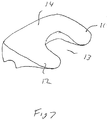
- Figure 3 shows an embodiment of the invention in which the upper surface of the upper end plate has a rectangular "cut out" from the front of a maverick end plate.
- the area which has been removed is generally rectangular in shape and as shown more clearly in Figure 7 comprises anterior lobes 11, 12 with a space 13 therebetween.
- the posterior region of the prosthesis remains substantially the same as an existing prosthesis upper end plate.
- the lower surface has a lower centre of radius of curvature in accordance with requirements of an earlier designed prosthesis.
- the load displacement characteristics of the standard maverick disc were tested against sawbone material using a roller bearing to allow lateral displacement and to compare the results with at least a machined surface.
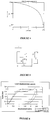
- Figure 6 shows a comparison of load displacement graphs of an unmodified prosthesis compared to a modified prosthesis as shown in Figure 5 . From this comparison the following observations can be made.
- an alternative strategy may be to provide an insert plate configured to move the centroid of the combined end plate and insert.
- a lower end plate may be provided with an insert plate to avoid redesigning the lower surface.
- Figures 8A to 8D show one embodiment of the lower end plate which has a central spherical region 20 which couples with an upper end plate having a similarly shaped recess (socket) formed in its lower surface.
- This insert plate would be attached to the adjacent vertebrae.
- the posterior region 16 of the plate 15 would effectively cover the majority of the posterior section of the lower end plate and the anterior region 17 would be provided with side lobes 18 and 19 to effectively build up the sides of the lower end plate.
- the result would be an effective recess being formed between the anterior sides of the lower end plate. This would result in effective movement of the centroid for the lower end plate towards the centre of rotation of curvature of the prosthesis.
- Figures 9A to 9D show an alternative embodiment of a lower end plate 30 which is generally more rectangular in shape than the previous embodiment. Underneath the insert plate a scalloped out region 31 is provided anteriorly with its centre aligned with the centre of the semi-spherical ball portion 32 on its upper surface.
- the scalloped out region 31 commences at a forward most end of the insert and curves concavely rearwardly to the bottom surface more than half of the way along the length of the end plate (measured from front to rear) to a point which is rearward of the centre of the semi-spherical ball portion 32. This effectively moves the centroid rearwardly.
- Figure 9B shows that the scalloped region is part circular in shape.
- the inserts shown in Figures 8A to 9D can be configured to couple with an upper end plate in a similar fashion to that shown in Figures 1 and 2 .
- the lower end of the adjacent vertebrae to the upper end plate may be physically altered so that a recess is provided in an anterior central section to provide a similar effect to that discussed above by providing a recess in the anterior central region of the upper end plate.
Landscapes
- Health & Medical Sciences (AREA)
- Engineering & Computer Science (AREA)
- Biomedical Technology (AREA)
- Orthopedic Medicine & Surgery (AREA)
- Neurology (AREA)
- Heart & Thoracic Surgery (AREA)
- Oral & Maxillofacial Surgery (AREA)
- Transplantation (AREA)
- Cardiology (AREA)
- Vascular Medicine (AREA)
- Life Sciences & Earth Sciences (AREA)
- Animal Behavior & Ethology (AREA)
- General Health & Medical Sciences (AREA)
- Public Health (AREA)
- Veterinary Medicine (AREA)
- Prostheses (AREA)
Claims (10)
- Zwischenwirbel-Prothese für eine Wirbelsäule, die zumindest ein oberes Teil zum Anbringen an einem oberen Wirbel und ein unteres Teil an einem unteren Wirbel aufweist, wobei das obere Teil eine gekrümmte Unterseite aufweist und das untere Teil eine gekrümmte Oberseite aufweist, wobei in situ ein Zentrum des Krümmungradius der gekrümmten Ober- und Unterseiten in Bezug auf eine zentrale vertikale Achse durch die oberen und unteren Wirbel, an denen das Zentrum des Krümmungradius angeordnet ist, zur posterioren Seite der Prothese hin nach hinten versetzt ist, wobei der Schwerpunkt einer Kontaktoberfläche von zumindest einem der oberen und unteren Teile im Wesentlichen auf der gleichen vertikalen Achse positioniert ist wie das Zentrum des Krümmungsradius, wobei die Kontaktoberfläche konfiguriert ist, um einen benachbarten Wirbel zu kontaktieren.
- Die Prothese von Anspruch 1, die ferner ein mittleres Teil aufweist, das in Bezug auf die oberen und unteren Teile schwenkbar und verlagerbar ist.
- Die Prothese von Anspruch 1, wobei das obere Teil und das untere Teil im Gebrauch relativ zueinander schwenkbar sind.
- Die Prothese von Anspruch 3, die einen Kern enthält, der in Bezug auf die oberen und unteren Teile schwenkbar und/oder verlagerbar ist.
- Die Prothese von Anspruch 3, wobei zumindest eines der oberen und unteren Prothesenteile einen Einsatz aufweist.
- Die Prothese von Anspruch 3, wobei die Kontaktoberfläche eine Oberseite des oberen Teils und/oder eine Unterseite des unteren Teils aufweist.
- Die Prothese von Anspruch 3, wobei ein Teil der Kontaktoberfläche ausgeschnitten ist.
- Die Prothese von Anspruch 3, wobei die Kontaktoberfläche mit einem vertieften Bereich versehen ist.
- Die Prothese von Anspruch 8, wobei der vertiefte Bereich zwischen entgegengesetzten Seiten eines anterioren Abschnitts der Kontaktoberfläche angeordnet ist.
- Die Prothese von Anspruch 1, wobei ein Abschnitt vor dem Schwerpunkt ausgeschnitten ist.
Applications Claiming Priority (2)
| Application Number | Priority Date | Filing Date | Title |
|---|---|---|---|
| AU2005906204A AU2005906204A0 (en) | 2005-11-04 | A method for reducing loading failure for a prosthetic component | |
| PCT/AU2006/001640 WO2007051247A1 (en) | 2005-11-04 | 2006-11-02 | A method of reducing loading failure for a prosthetic component |
Publications (3)
| Publication Number | Publication Date |
|---|---|
| EP1945148A1 EP1945148A1 (de) | 2008-07-23 |
| EP1945148A4 EP1945148A4 (de) | 2010-03-17 |
| EP1945148B1 true EP1945148B1 (de) | 2019-07-03 |
Family
ID=38005356
Family Applications (1)
| Application Number | Title | Priority Date | Filing Date |
|---|---|---|---|
| EP06804463.5A Not-in-force EP1945148B1 (de) | 2005-11-04 | 2006-11-02 | Bandscheibenprothese |
Country Status (9)
| Country | Link |
|---|---|
| US (1) | US10045856B2 (de) |
| EP (1) | EP1945148B1 (de) |
| JP (1) | JP2009514568A (de) |
| KR (1) | KR101360188B1 (de) |
| CN (1) | CN101340863B (de) |
| BR (1) | BRPI0618264A2 (de) |
| CA (1) | CA2628236A1 (de) |
| WO (1) | WO2007051247A1 (de) |
| ZA (1) | ZA200804260B (de) |
Families Citing this family (4)
| Publication number | Priority date | Publication date | Assignee | Title |
|---|---|---|---|---|
| US11234838B2 (en) | 2018-09-07 | 2022-02-01 | Additive Implants, Inc. | Dynamic intervertebral spacer implant |
| US10299938B1 (en) | 2018-09-07 | 2019-05-28 | John R. Ehteshami | Dynamic intervertebral spacer implant |
| US11684482B2 (en) | 2018-12-20 | 2023-06-27 | Additive Implants, Inc. | Spondylolisthesis system and methods |
| US11123201B2 (en) | 2019-09-24 | 2021-09-21 | Additive Implants, Inc. | Intervertebral spacer |
Family Cites Families (28)
| Publication number | Priority date | Publication date | Assignee | Title |
|---|---|---|---|---|
| FR2659226B1 (fr) * | 1990-03-07 | 1992-05-29 | Jbs Sa | Prothese pour disques intervertebraux et ses instruments d'implantation. |
| US5425773A (en) * | 1992-01-06 | 1995-06-20 | Danek Medical, Inc. | Intervertebral disk arthroplasty device |
| US5258031A (en) * | 1992-01-06 | 1993-11-02 | Danek Medical | Intervertebral disk arthroplasty |
| JPH06178787A (ja) * | 1992-12-14 | 1994-06-28 | Shima Yumiko | 関節付椎体スペーサ、椎間腔計測器および椎体スペーサ模型 |
| US5676701A (en) * | 1993-01-14 | 1997-10-14 | Smith & Nephew, Inc. | Low wear artificial spinal disc |
| US5888226A (en) * | 1997-11-12 | 1999-03-30 | Rogozinski; Chaim | Intervertebral prosthetic disc |
| US6679915B1 (en) * | 1998-04-23 | 2004-01-20 | Sdgi Holdings, Inc. | Articulating spinal implant |
| CN2333369Y (zh) * | 1998-05-29 | 1999-08-18 | 中山医科大学孙逸仙纪念医院 | 人工腰椎间盘 |
| DE59904848D1 (de) * | 1999-05-21 | 2003-05-08 | Link Waldemar Gmbh Co | Zwischenwirbel-Endoprothese mit einer gezahnten Anschlussplatte |
| ES2206338T3 (es) * | 1999-10-19 | 2004-05-16 | Sdgi Holdings, Inc. | Implante espinal y accesorio preparatorio de la herramienta de corte para el montaje del implante. |
| US6989032B2 (en) * | 2001-07-16 | 2006-01-24 | Spinecore, Inc. | Artificial intervertebral disc |
| WO2003065929A2 (en) * | 2002-02-07 | 2003-08-14 | Ebi, L.P. | Anterior spinal implant |
| US6706068B2 (en) * | 2002-04-23 | 2004-03-16 | Bret A. Ferree | Artificial disc replacements with natural kinematics |
| US7001433B2 (en) * | 2002-05-23 | 2006-02-21 | Pioneer Laboratories, Inc. | Artificial intervertebral disc device |
| US20040143332A1 (en) | 2002-10-31 | 2004-07-22 | Krueger David J. | Movable disc implant |
| GB0301085D0 (en) * | 2003-01-17 | 2003-02-19 | Krishna Manoj | Articulating spinal disc prosthesis |
| US20040158254A1 (en) * | 2003-02-12 | 2004-08-12 | Sdgi Holdings, Inc. | Instrument and method for milling a path into bone |
| US7326251B2 (en) * | 2003-04-01 | 2008-02-05 | Sdgi Holdings, Inc. | Interbody fusion device |
| US7621956B2 (en) * | 2003-07-31 | 2009-11-24 | Globus Medical, Inc. | Prosthetic spinal disc replacement |
| US7794465B2 (en) * | 2003-09-10 | 2010-09-14 | Warsaw Orthopedic, Inc. | Artificial spinal discs and associated implantation instruments and methods |
| GB0325421D0 (en) * | 2003-10-30 | 2003-12-03 | Gill Steven S | An intervertebral prosthesis |
| US7691146B2 (en) * | 2003-11-21 | 2010-04-06 | Kyphon Sarl | Method of laterally inserting an artificial vertebral disk replacement implant with curved spacer |
| US20050154462A1 (en) * | 2003-12-02 | 2005-07-14 | St. Francis Medical Technologies, Inc. | Laterally insertable artificial vertebral disk replacement implant with translating pivot point |
| WO2005081884A2 (en) * | 2004-02-20 | 2005-09-09 | Spinecore, Inc. | Artificial intervertebral disc having a universal joint |
| ATE438360T1 (de) * | 2004-09-08 | 2009-08-15 | Synthes Gmbh | Universal-bandscheibenprothese |
| US7582115B2 (en) * | 2004-09-30 | 2009-09-01 | Helmut Weber | Intervertebral prosthesis |
| US7566346B2 (en) * | 2004-10-29 | 2009-07-28 | X-Spine Systems, Inc. | Prosthetic implant and method |
| US7887589B2 (en) * | 2004-11-23 | 2011-02-15 | Glenn Bradley J | Minimally invasive spinal disc stabilizer and insertion tool |
-
2006
- 2006-11-02 EP EP06804463.5A patent/EP1945148B1/de not_active Not-in-force
- 2006-11-02 JP JP2008538227A patent/JP2009514568A/ja active Pending
- 2006-11-02 CA CA002628236A patent/CA2628236A1/en not_active Abandoned
- 2006-11-02 KR KR1020087013434A patent/KR101360188B1/ko not_active Expired - Fee Related
- 2006-11-02 BR BRPI0618264-0A patent/BRPI0618264A2/pt not_active Application Discontinuation
- 2006-11-02 WO PCT/AU2006/001640 patent/WO2007051247A1/en not_active Ceased
- 2006-11-02 CN CN2006800463789A patent/CN101340863B/zh not_active Expired - Fee Related
- 2006-11-02 US US12/084,471 patent/US10045856B2/en active Active
-
2008
- 2008-05-16 ZA ZA200804260A patent/ZA200804260B/xx unknown
Non-Patent Citations (1)
| Title |
|---|
| None * |
Also Published As
| Publication number | Publication date |
|---|---|
| CN101340863B (zh) | 2013-04-03 |
| US20100331982A1 (en) | 2010-12-30 |
| CA2628236A1 (en) | 2007-05-10 |
| CN101340863A (zh) | 2009-01-07 |
| EP1945148A1 (de) | 2008-07-23 |
| KR20080084934A (ko) | 2008-09-22 |
| KR101360188B1 (ko) | 2014-02-11 |
| BRPI0618264A2 (pt) | 2011-08-23 |
| EP1945148A4 (de) | 2010-03-17 |
| JP2009514568A (ja) | 2009-04-09 |
| ZA200804260B (en) | 2009-01-28 |
| US10045856B2 (en) | 2018-08-14 |
| WO2007051247A1 (en) | 2007-05-10 |
Similar Documents
| Publication | Publication Date | Title |
|---|---|---|
| CA2595266C (en) | Elastomeric intervertebral disc prosthesis | |
| US8556973B2 (en) | Intervertebral disc prosthesis having multiple bearing surfaces | |
| JP4990296B2 (ja) | 椎間板置換装置 | |
| US10226354B2 (en) | Prosthesis | |
| KR20080064184A (ko) | 척추간 임플란트 | |
| US20110264223A1 (en) | Self-adjusting and self-stabilizing intervertebral disc prothesis | |
| EP1945148B1 (de) | Bandscheibenprothese | |
| Rohlmann et al. | Effect of position and height of a mobile core type artificial disc on the biomechanical behaviour of the lumbar spine | |
| AU2014280965B2 (en) | A method of reducing loading failure for a prosthetic component | |
| AU2006308801B2 (en) | A method of reducing loading failure for a prosthetic component | |
| JP2010528788A (ja) | 人工椎間板 | |
| AU2012203631A1 (en) | A method of reducing loading failure for a prosthetic component | |
| MX2008005811A (en) | A method of reducing loading failure for a prosthetic component | |
| AU2006230808A1 (en) | Vertebral disc prosthesis |
Legal Events
| Date | Code | Title | Description |
|---|---|---|---|
| PUAI | Public reference made under article 153(3) epc to a published international application that has entered the european phase |
Free format text: ORIGINAL CODE: 0009012 |
|
| 17P | Request for examination filed |
Effective date: 20080528 |
|
| AK | Designated contracting states |
Kind code of ref document: A1 Designated state(s): AT BE BG CH CY CZ DE DK EE ES FI FR GB GR HU IE IS IT LI LT LU LV MC NL PL PT RO SE SI SK TR |
|
| A4 | Supplementary search report drawn up and despatched |
Effective date: 20100215 |
|
| 17Q | First examination report despatched |
Effective date: 20120405 |
|
| DAX | Request for extension of the european patent (deleted) | ||
| RAP1 | Party data changed (applicant data changed or rights of an application transferred) |
Owner name: NUVASIVE, INC. |
|
| RIN1 | Information on inventor provided before grant (corrected) |
Inventor name: NUVASIVE, INC. |
|
| GRAP | Despatch of communication of intention to grant a patent |
Free format text: ORIGINAL CODE: EPIDOSNIGR1 |
|
| STAA | Information on the status of an ep patent application or granted ep patent |
Free format text: STATUS: GRANT OF PATENT IS INTENDED |
|
| INTG | Intention to grant announced |
Effective date: 20190121 |
|
| RIN1 | Information on inventor provided before grant (corrected) |
Inventor name: MCCOMBE PETER |
|
| GRAS | Grant fee paid |
Free format text: ORIGINAL CODE: EPIDOSNIGR3 |
|
| GRAA | (expected) grant |
Free format text: ORIGINAL CODE: 0009210 |
|
| STAA | Information on the status of an ep patent application or granted ep patent |
Free format text: STATUS: THE PATENT HAS BEEN GRANTED |
|
| AK | Designated contracting states |
Kind code of ref document: B1 Designated state(s): AT BE BG CH CY CZ DE DK EE ES FI FR GB GR HU IE IS IT LI LT LU LV MC NL PL PT RO SE SI SK TR |
|
| REG | Reference to a national code |
Ref country code: GB Ref legal event code: FG4D |
|
| REG | Reference to a national code |
Ref country code: CH Ref legal event code: EP Ref country code: AT Ref legal event code: REF Ref document number: 1150074 Country of ref document: AT Kind code of ref document: T Effective date: 20190715 |
|
| REG | Reference to a national code |
Ref country code: DE Ref legal event code: R096 Ref document number: 602006058260 Country of ref document: DE |
|
| REG | Reference to a national code |
Ref country code: IE Ref legal event code: FG4D |
|
| REG | Reference to a national code |
Ref country code: NL Ref legal event code: MP Effective date: 20190703 |
|
| REG | Reference to a national code |
Ref country code: LT Ref legal event code: MG4D |
|
| REG | Reference to a national code |
Ref country code: AT Ref legal event code: MK05 Ref document number: 1150074 Country of ref document: AT Kind code of ref document: T Effective date: 20190703 |
|
| PG25 | Lapsed in a contracting state [announced via postgrant information from national office to epo] |
Ref country code: CZ Free format text: LAPSE BECAUSE OF FAILURE TO SUBMIT A TRANSLATION OF THE DESCRIPTION OR TO PAY THE FEE WITHIN THE PRESCRIBED TIME-LIMIT Effective date: 20190703 Ref country code: SE Free format text: LAPSE BECAUSE OF FAILURE TO SUBMIT A TRANSLATION OF THE DESCRIPTION OR TO PAY THE FEE WITHIN THE PRESCRIBED TIME-LIMIT Effective date: 20190703 Ref country code: PT Free format text: LAPSE BECAUSE OF FAILURE TO SUBMIT A TRANSLATION OF THE DESCRIPTION OR TO PAY THE FEE WITHIN THE PRESCRIBED TIME-LIMIT Effective date: 20191104 Ref country code: FI Free format text: LAPSE BECAUSE OF FAILURE TO SUBMIT A TRANSLATION OF THE DESCRIPTION OR TO PAY THE FEE WITHIN THE PRESCRIBED TIME-LIMIT Effective date: 20190703 Ref country code: LT Free format text: LAPSE BECAUSE OF FAILURE TO SUBMIT A TRANSLATION OF THE DESCRIPTION OR TO PAY THE FEE WITHIN THE PRESCRIBED TIME-LIMIT Effective date: 20190703 Ref country code: BG Free format text: LAPSE BECAUSE OF FAILURE TO SUBMIT A TRANSLATION OF THE DESCRIPTION OR TO PAY THE FEE WITHIN THE PRESCRIBED TIME-LIMIT Effective date: 20191003 Ref country code: NL Free format text: LAPSE BECAUSE OF FAILURE TO SUBMIT A TRANSLATION OF THE DESCRIPTION OR TO PAY THE FEE WITHIN THE PRESCRIBED TIME-LIMIT Effective date: 20190703 Ref country code: AT Free format text: LAPSE BECAUSE OF FAILURE TO SUBMIT A TRANSLATION OF THE DESCRIPTION OR TO PAY THE FEE WITHIN THE PRESCRIBED TIME-LIMIT Effective date: 20190703 |
|
| PG25 | Lapsed in a contracting state [announced via postgrant information from national office to epo] |
Ref country code: ES Free format text: LAPSE BECAUSE OF FAILURE TO SUBMIT A TRANSLATION OF THE DESCRIPTION OR TO PAY THE FEE WITHIN THE PRESCRIBED TIME-LIMIT Effective date: 20190703 Ref country code: IS Free format text: LAPSE BECAUSE OF FAILURE TO SUBMIT A TRANSLATION OF THE DESCRIPTION OR TO PAY THE FEE WITHIN THE PRESCRIBED TIME-LIMIT Effective date: 20191103 Ref country code: LV Free format text: LAPSE BECAUSE OF FAILURE TO SUBMIT A TRANSLATION OF THE DESCRIPTION OR TO PAY THE FEE WITHIN THE PRESCRIBED TIME-LIMIT Effective date: 20190703 Ref country code: GR Free format text: LAPSE BECAUSE OF FAILURE TO SUBMIT A TRANSLATION OF THE DESCRIPTION OR TO PAY THE FEE WITHIN THE PRESCRIBED TIME-LIMIT Effective date: 20191004 |
|
| PG25 | Lapsed in a contracting state [announced via postgrant information from national office to epo] |
Ref country code: TR Free format text: LAPSE BECAUSE OF FAILURE TO SUBMIT A TRANSLATION OF THE DESCRIPTION OR TO PAY THE FEE WITHIN THE PRESCRIBED TIME-LIMIT Effective date: 20190703 |
|
| PG25 | Lapsed in a contracting state [announced via postgrant information from national office to epo] |
Ref country code: IT Free format text: LAPSE BECAUSE OF FAILURE TO SUBMIT A TRANSLATION OF THE DESCRIPTION OR TO PAY THE FEE WITHIN THE PRESCRIBED TIME-LIMIT Effective date: 20190703 Ref country code: RO Free format text: LAPSE BECAUSE OF FAILURE TO SUBMIT A TRANSLATION OF THE DESCRIPTION OR TO PAY THE FEE WITHIN THE PRESCRIBED TIME-LIMIT Effective date: 20190703 Ref country code: DK Free format text: LAPSE BECAUSE OF FAILURE TO SUBMIT A TRANSLATION OF THE DESCRIPTION OR TO PAY THE FEE WITHIN THE PRESCRIBED TIME-LIMIT Effective date: 20190703 Ref country code: PL Free format text: LAPSE BECAUSE OF FAILURE TO SUBMIT A TRANSLATION OF THE DESCRIPTION OR TO PAY THE FEE WITHIN THE PRESCRIBED TIME-LIMIT Effective date: 20190703 Ref country code: EE Free format text: LAPSE BECAUSE OF FAILURE TO SUBMIT A TRANSLATION OF THE DESCRIPTION OR TO PAY THE FEE WITHIN THE PRESCRIBED TIME-LIMIT Effective date: 20190703 |
|
| PG25 | Lapsed in a contracting state [announced via postgrant information from national office to epo] |
Ref country code: IS Free format text: LAPSE BECAUSE OF FAILURE TO SUBMIT A TRANSLATION OF THE DESCRIPTION OR TO PAY THE FEE WITHIN THE PRESCRIBED TIME-LIMIT Effective date: 20200224 Ref country code: SK Free format text: LAPSE BECAUSE OF FAILURE TO SUBMIT A TRANSLATION OF THE DESCRIPTION OR TO PAY THE FEE WITHIN THE PRESCRIBED TIME-LIMIT Effective date: 20190703 |
|
| REG | Reference to a national code |
Ref country code: DE Ref legal event code: R097 Ref document number: 602006058260 Country of ref document: DE |
|
| REG | Reference to a national code |
Ref country code: CH Ref legal event code: PL |
|
| PLBE | No opposition filed within time limit |
Free format text: ORIGINAL CODE: 0009261 |
|
| STAA | Information on the status of an ep patent application or granted ep patent |
Free format text: STATUS: NO OPPOSITION FILED WITHIN TIME LIMIT |
|
| PG2D | Information on lapse in contracting state deleted |
Ref country code: IS |
|
| PG25 | Lapsed in a contracting state [announced via postgrant information from national office to epo] |
Ref country code: CH Free format text: LAPSE BECAUSE OF NON-PAYMENT OF DUE FEES Effective date: 20191130 Ref country code: MC Free format text: LAPSE BECAUSE OF FAILURE TO SUBMIT A TRANSLATION OF THE DESCRIPTION OR TO PAY THE FEE WITHIN THE PRESCRIBED TIME-LIMIT Effective date: 20190703 Ref country code: LU Free format text: LAPSE BECAUSE OF NON-PAYMENT OF DUE FEES Effective date: 20191102 Ref country code: LI Free format text: LAPSE BECAUSE OF NON-PAYMENT OF DUE FEES Effective date: 20191130 |
|
| 26N | No opposition filed |
Effective date: 20200603 |
|
| REG | Reference to a national code |
Ref country code: BE Ref legal event code: MM Effective date: 20191130 |
|
| PG25 | Lapsed in a contracting state [announced via postgrant information from national office to epo] |
Ref country code: SI Free format text: LAPSE BECAUSE OF FAILURE TO SUBMIT A TRANSLATION OF THE DESCRIPTION OR TO PAY THE FEE WITHIN THE PRESCRIBED TIME-LIMIT Effective date: 20190703 |
|
| PG25 | Lapsed in a contracting state [announced via postgrant information from national office to epo] |
Ref country code: IE Free format text: LAPSE BECAUSE OF NON-PAYMENT OF DUE FEES Effective date: 20191102 Ref country code: FR Free format text: LAPSE BECAUSE OF NON-PAYMENT OF DUE FEES Effective date: 20191130 |
|
| PG25 | Lapsed in a contracting state [announced via postgrant information from national office to epo] |
Ref country code: BE Free format text: LAPSE BECAUSE OF NON-PAYMENT OF DUE FEES Effective date: 20191130 |
|
| PG25 | Lapsed in a contracting state [announced via postgrant information from national office to epo] |
Ref country code: CY Free format text: LAPSE BECAUSE OF FAILURE TO SUBMIT A TRANSLATION OF THE DESCRIPTION OR TO PAY THE FEE WITHIN THE PRESCRIBED TIME-LIMIT Effective date: 20190703 |
|
| PG25 | Lapsed in a contracting state [announced via postgrant information from national office to epo] |
Ref country code: HU Free format text: LAPSE BECAUSE OF FAILURE TO SUBMIT A TRANSLATION OF THE DESCRIPTION OR TO PAY THE FEE WITHIN THE PRESCRIBED TIME-LIMIT; INVALID AB INITIO Effective date: 20061102 |
|
| PGFP | Annual fee paid to national office [announced via postgrant information from national office to epo] |
Ref country code: DE Payment date: 20230428 Year of fee payment: 17 |
|
| PGFP | Annual fee paid to national office [announced via postgrant information from national office to epo] |
Ref country code: GB Payment date: 20230428 Year of fee payment: 17 |
|
| REG | Reference to a national code |
Ref country code: DE Ref legal event code: R119 Ref document number: 602006058260 Country of ref document: DE |
|
| GBPC | Gb: european patent ceased through non-payment of renewal fee |
Effective date: 20231102 |
|
| PG25 | Lapsed in a contracting state [announced via postgrant information from national office to epo] |
Ref country code: DE Free format text: LAPSE BECAUSE OF NON-PAYMENT OF DUE FEES Effective date: 20240601 |
|
| PG25 | Lapsed in a contracting state [announced via postgrant information from national office to epo] |
Ref country code: GB Free format text: LAPSE BECAUSE OF NON-PAYMENT OF DUE FEES Effective date: 20231102 |
|
| PG25 | Lapsed in a contracting state [announced via postgrant information from national office to epo] |
Ref country code: GB Free format text: LAPSE BECAUSE OF NON-PAYMENT OF DUE FEES Effective date: 20231102 Ref country code: DE Free format text: LAPSE BECAUSE OF NON-PAYMENT OF DUE FEES Effective date: 20240601 |