EP2301202B1 - Dispositif de commande et/ou de surveillance et de demande de données à partir d'unités de fonction décentralisées agencées le long d'un réseau de trafic - Google Patents
Dispositif de commande et/ou de surveillance et de demande de données à partir d'unités de fonction décentralisées agencées le long d'un réseau de trafic Download PDFInfo
- Publication number
- EP2301202B1 EP2301202B1 EP08735265.4A EP08735265A EP2301202B1 EP 2301202 B1 EP2301202 B1 EP 2301202B1 EP 08735265 A EP08735265 A EP 08735265A EP 2301202 B1 EP2301202 B1 EP 2301202B1
- Authority
- EP
- European Patent Office
- Prior art keywords
- functional units
- dfe
- decentralised
- subnetwork
- network
- Prior art date
- Legal status (The legal status is an assumption and is not a legal conclusion. Google has not performed a legal analysis and makes no representation as to the accuracy of the status listed.)
- Active
Links
- 238000004891 communication Methods 0.000 title claims description 38
- 238000012544 monitoring process Methods 0.000 title claims description 20
- 230000005540 biological transmission Effects 0.000 claims description 19
- 238000000034 method Methods 0.000 claims description 18
- 238000012546 transfer Methods 0.000 claims description 14
- 230000008878 coupling Effects 0.000 claims description 10
- 238000010168 coupling process Methods 0.000 claims description 10
- 238000005859 coupling reaction Methods 0.000 claims description 10
- 238000012545 processing Methods 0.000 claims description 3
- 239000004020 conductor Substances 0.000 description 4
- 239000010949 copper Substances 0.000 description 4
- RYGMFSIKBFXOCR-UHFFFAOYSA-N Copper Chemical compound [Cu] RYGMFSIKBFXOCR-UHFFFAOYSA-N 0.000 description 3
- 238000010276 construction Methods 0.000 description 3
- 229910052802 copper Inorganic materials 0.000 description 3
- 238000013461 design Methods 0.000 description 2
- 230000000694 effects Effects 0.000 description 2
- 238000005516 engineering process Methods 0.000 description 2
- 239000000835 fiber Substances 0.000 description 2
- 230000008569 process Effects 0.000 description 2
- 238000013459 approach Methods 0.000 description 1
- 230000008859 change Effects 0.000 description 1
- 238000006073 displacement reaction Methods 0.000 description 1
- 230000009977 dual effect Effects 0.000 description 1
- 230000006872 improvement Effects 0.000 description 1
- 238000012423 maintenance Methods 0.000 description 1
- 230000003287 optical effect Effects 0.000 description 1
- 210000002023 somite Anatomy 0.000 description 1
- 238000011144 upstream manufacturing Methods 0.000 description 1
Images
Classifications
-
- H—ELECTRICITY
- H04—ELECTRIC COMMUNICATION TECHNIQUE
- H04L—TRANSMISSION OF DIGITAL INFORMATION, e.g. TELEGRAPHIC COMMUNICATION
- H04L12/00—Data switching networks
- H04L12/28—Data switching networks characterised by path configuration, e.g. LAN [Local Area Networks] or WAN [Wide Area Networks]
- H04L12/46—Interconnection of networks
- H04L12/4604—LAN interconnection over a backbone network, e.g. Internet, Frame Relay
-
- B—PERFORMING OPERATIONS; TRANSPORTING
- B61—RAILWAYS
- B61L—GUIDING RAILWAY TRAFFIC; ENSURING THE SAFETY OF RAILWAY TRAFFIC
- B61L19/00—Arrangements for interlocking between points and signals by means of a single interlocking device, e.g. central control
- B61L19/06—Interlocking devices having electrical operation
-
- B—PERFORMING OPERATIONS; TRANSPORTING
- B61—RAILWAYS
- B61L—GUIDING RAILWAY TRAFFIC; ENSURING THE SAFETY OF RAILWAY TRAFFIC
- B61L21/00—Station blocking between signal boxes in one yard
- B61L21/04—Electrical locking and release of the route; Electrical repeat locks
-
- B—PERFORMING OPERATIONS; TRANSPORTING
- B61—RAILWAYS
- B61L—GUIDING RAILWAY TRAFFIC; ENSURING THE SAFETY OF RAILWAY TRAFFIC
- B61L27/00—Central railway traffic control systems; Trackside control; Communication systems specially adapted therefor
- B61L27/20—Trackside control of safe travel of vehicle or train, e.g. braking curve calculation
-
- B—PERFORMING OPERATIONS; TRANSPORTING
- B61—RAILWAYS
- B61L—GUIDING RAILWAY TRAFFIC; ENSURING THE SAFETY OF RAILWAY TRAFFIC
- B61L27/00—Central railway traffic control systems; Trackside control; Communication systems specially adapted therefor
- B61L27/70—Details of trackside communication
-
- H—ELECTRICITY
- H04—ELECTRIC COMMUNICATION TECHNIQUE
- H04L—TRANSMISSION OF DIGITAL INFORMATION, e.g. TELEGRAPHIC COMMUNICATION
- H04L12/00—Data switching networks
- H04L12/28—Data switching networks characterised by path configuration, e.g. LAN [Local Area Networks] or WAN [Wide Area Networks]
- H04L12/42—Loop networks
- H04L12/427—Loop networks with decentralised control
- H04L12/43—Loop networks with decentralised control with synchronous transmission, e.g. time division multiplex [TDM], slotted rings
-
- H—ELECTRICITY
- H04—ELECTRIC COMMUNICATION TECHNIQUE
- H04L—TRANSMISSION OF DIGITAL INFORMATION, e.g. TELEGRAPHIC COMMUNICATION
- H04L12/00—Data switching networks
- H04L12/28—Data switching networks characterised by path configuration, e.g. LAN [Local Area Networks] or WAN [Wide Area Networks]
- H04L12/42—Loop networks
- H04L12/437—Ring fault isolation or reconfiguration
-
- B—PERFORMING OPERATIONS; TRANSPORTING
- B61—RAILWAYS
- B61L—GUIDING RAILWAY TRAFFIC; ENSURING THE SAFETY OF RAILWAY TRAFFIC
- B61L27/00—Central railway traffic control systems; Trackside control; Communication systems specially adapted therefor
- B61L27/20—Trackside control of safe travel of vehicle or train, e.g. braking curve calculation
- B61L2027/202—Trackside control of safe travel of vehicle or train, e.g. braking curve calculation using European Train Control System [ETCS]
-
- H—ELECTRICITY
- H04—ELECTRIC COMMUNICATION TECHNIQUE
- H04L—TRANSMISSION OF DIGITAL INFORMATION, e.g. TELEGRAPHIC COMMUNICATION
- H04L12/00—Data switching networks
- H04L12/28—Data switching networks characterised by path configuration, e.g. LAN [Local Area Networks] or WAN [Wide Area Networks]
- H04L12/46—Interconnection of networks
- H04L12/4637—Interconnected ring systems
Definitions
- the present invention relates to a device and a method for controlling and / or monitoring as well as for data retrieval and data exchange of decentralized functional units arranged along a traffic network.
- Such remote functional units are used in particular in rail networks, such as the railways, where they are used to control and monitor vehicle influencing and / or vehicle monitoring units, and to record and report back process data.
- As Switzerlandbeeinlende units that give instructions to the driver or even make direct intervention in the vehicle control or directly set a safe track, for example, signals, points, balises, line conductors, track magnets and the like, as well as sensors for detecting process variables of the moving train, such as power consumption, speed and the like.
- train and track section monitoring units can also be called balises and line conductors, but also axle counters and track circuits.
- these decentralized functional units are controlled by a signal box or a remote control computer.
- a signal box or a remote control computer For the data transfer between the interlocking and the functional units in the track area today standardized copper cables are usually provided, for their classical travel distances because of the physical transmission parameters, the cable coverings (RLC), at 10 km in practice is the upper limit. For certain types of However, functional units, this upper limit can only be at a maximum of 6.5 km.
- DTN data transport network
- Illustrative examples of applications for such data networks are branch lines or routes with ETCS level 2 or long tunnels, for which an arrangement of interlocking computers within tunnels is still required today because of the limits for the travel distances with conventional interlocking cables.
- the harsh operating conditions prevailing there require the interlocking computers to be encapsulated in caverns or containers and to be air-conditioned become. The maintenance is correspondingly expensive in these cases.
- Outdoor equipment parts can not be arbitrarily far apart.
- the novel data networks have a disadvantage in that basically each centralized and decentralized functional unit must be coupled in a suitable manner via an access point and for reasons of availability in a redundant manner to such a data network.
- a comparatively high outlay for the coupling to the data network is currently required at a single network node for a connection of a functional unit, while at the same time only a comparatively low data transfer rate in relation to the network capacity.
- today's fiber optic networks allow, for example, transmission rates from GigaBit up to TeraBit transfer performance, these transmission rates are only used very marginally in these security applications.
- JP 2006 281960 A a device for controlling and / or monitoring decentralized functional units arranged along a traffic network.
- EP 0 893 894 A2 a so-called "dual hubbed hierarchical ring topology" in which communication nodes are arranged in annular subnetworks.
- the present invention is therefore based on the object of specifying a device and a method for controlling and / or monitoring decentralized functional units arranged along a traffic network, which, on the one hand, make use of the advantages of a digital data transport network and, on the other hand, the associated expense, like the Cabling effort, while significantly reducing high availability.
- a digital transport network can be used for the coupling of the decentralized functional units, which is robust in each case against a simple error event, yet a very clever use of very widely used in railway engineering Cu cables, for example, previously existing interlocking cables allowed and finally only a comparatively small number of network access points needed.
- Such a device is used in a particularly advantageous manner for a rail network for rail transport. Consequently, it is then expedient in a further advantageous embodiment, by means of the decentralized functional units traffic monitoring and traffic control functional units, such as in particular signals, switches, axle counter, track circuits, point and line train control elements to couple to the data transport network.
- traffic monitoring and traffic control functional units such as in particular signals, switches, axle counter, track circuits, point and line train control elements to couple to the data transport network.
- the density of the spatial arrangement of decentralized functional unit is naturally very different in a railway network and, in addition to many other factors, also depends on the complexity of the network topology. This circumstance can be particularly well taken into account in a further advantageous embodiment of the invention, if a first connection type for a subset of decentralized functional unit having a first average density per unit area unit and the second connection type for a subset of decentralized functional units with a second average density per unit area unit are provided, wherein the first average density is greater than the second average density.
- the first type of connection is provided for decentralized functional units arranged in a station area and the second type of connection is provided for decentralized functional units arranged on the free distance.
- the wiring harness for the second type of connection relies on the interlocking cables running in each case from adjacent interlocking systems and only one middle section is to be used in order to connect the two interlocking cables and thus to realize the network loop in a wire-saving manner.
- the data transport to and from the decentralized functional units can take place simultaneously via both ends of the subnetwork.
- a data telegram arriving first at the decentralized functional unit and a data telegram arriving at the higher-level control system first from the decentralized functional unit is then utilized for further processing; the second via the then each redundant way incoming data telegram is discarded.
- the higher-level control system and the decentralized functional unit can have corresponding processing routines that examine incoming data telegrams to determine whether an identical data telegram has already been received previously.
- An alternative approach may then provide that the data transport to and from the decentralized functional units (DFE) is made via one of the two ends of the subnetwork, in the event of a failure of the communication unit and / or the network access point at this end of the subnetwork to a Data transfer over the other end of the subnetwork is switched. Accordingly, in the event of a default, a decentralized Function unit (DFE) and / or in the case of an interruption of the subnetwork then the information flow through the transport network (OTN) cut off decentralized functional units via the other end of the subnetwork re-integrated into the flow of information.
- DFE decentralized Functional unit
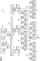
- FIG. 1 3 shows a schematic view of the construction of a device E for controlling and / or monitoring decentralized functional units DFE1A to DFEnA arranged along a railway network (not shown here), DFE1B to DFEnB and so on.
- the decentralized functional units will be referred to below as DFE.
- Such decentralized functional units DFE are used to control and monitor train-influencing and / or train monitoring units.
- signals, switches, balises, line conductors, track magnets and the like may be mentioned.
- Train monitoring units can also include balises and line conductors, as well as axle counters and track circuits.
- a signal S is controlled and monitored by the decentralized functional unit DFE1C.
- the decentralized functional unit controls the display of the signal terms and performs respectively assisted in monitoring functions, such as the monitoring of the lamp current in the signal.
- Each distributed functional unit DFE or the controlled / monitored unit has a unique address throughout the network, for example an IP address or a MAC address.
- the device E further comprises a data transport network TN with a number of network access points 2 to 16. At a portion of these network access points 6 to 16 communication units 18 to 28 are connected.
- the data transport network TN is designed here as a highly available network. Such highly available structures can arise on the one hand by a redundant design of the network itself and / or on the other hand by a clever re-organization of the network in the event of failure of a connector.
- the device E comprises a higher-level control system 30, which in addition to other components not further listed here, a control center LT, an interlocking computer STW, a Achsterrorismerrechner AZ and a Service / diagnostic unit SD includes the network access points 2 and 4 are connected by means of Ethernet connections to the data transport network TN.
- the decentralized functional units DFE must be coupled to the transport network TN via one of the communication groups 18 to 28 and the corresponding network node 6 to 16 and can thus receive or exchange data telegrams via this.
- the decentralized functional units DFE are combined to subgroups A, B, C, D and E, each with its own subnetwork NA, NB, NC, ND and NE.
- the subgroup A is formed, for example, from the decentralized functional units DFE1A, DFE2A, DFE3A to DFEnA.
- the subgroups A to E are always connected at their two ends with one of the communication groups 18 to 28 and a network access points 6 to 16.
- Each decentralized functional unit DFE is also a switching computer SU, which can alternatively also be integrated directly into the decentralized functional unit DFE, upstream, which provides the connection to the subnetwork for the decentralized functional units DFE, so that each decentralized functional unit DFE in case of failure of a communication group of one second redundant communication group can be addressed.
- Each subnetwork (NA to NE) is thus made up of a number of point-to-point connections of logically adjacent distributed functional units (DFE).
- DFE distributed functional units
- a point-to-point connection is formed as an autonomous transmission path within the subnetwork, for example as an ISDN transmission path or as an xDSL transmission path or fiber optic transmission path.
- a single subnetwork can be constructed, so to speak, of individual transmission cells, which in turn always only have to master the transmission from point to point. In other words, you can speak for example from simple, rather short-range Transmission techniques also a much longer and more complex subnetwork.
- a suitable switching module (SU) may for this purpose be designed such that it provides a number of point-to-point transmission techniques and, depending on the circuitry, self-organizingly provides the point-to-point transmission technique determined by the circuitry.
- the subgroups A to E are each connected to a first connection type or a second connection type to the two communication groups 18 to 28.
- first type of connection as shown for subgroups A, C and E, for example, the associated subnetwork NA, NC and NE are terminated in two geographically close communication groups 18 and 20 or 22 and 24 or 26 and 28, respectively FIG. 1 should be shown by the immediate vicinity of the communication group pairs 18, 20 and 22, 24 and 26, 28.
- second type of connection as shown for subgroups B and D, the respective subnetwork NB or ND is terminated with the communication groups 20, 22 or 24, 26 that are located further apart from each other.
- each subgroup B and D is still connected to another communication group in case of failure of one of the two associated communication groups.
- the subgroups A, C and E are more likely to be the decentralized functional units DFE located in the station area.
- the subgroups B and D represent more such decentralized Function units DFE, which are arranged in the area between two stations on free distance.
- the copper cables, which are too large can be used to save energy, which is explained using the example of subgroup B.
- the decentralized functional units DFE1B, DFE2B and DFE3B were driven from the station at the network access point 8.
- the remaining decentralized network access points DFEnB were controlled from the station at the network access point 10.
- the establishment of a connection sufficed only between the decentralized functional units DFE3B and DFEnB in order to interconnect the subgroup B in the subnetwork NB.
- the telegram types have assigned fixed timeslots.
- the assignment can be fixed during operation and can be configured offline, for example in the ratio of at least 1 to 10.
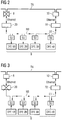
- FIG. 2 now shows the failure of a network access point 8, to which one end of the subnetwork NB of the subgroup B is connected via the communication unit 20.
- the FIG. 2 illustrates vividly that for the decentralized functional units DFE1B to DFEnB certain data telegrams DT (see the direction of the arrows on the subnetwork NB) are now performed more only about the network access point 10 and the communication unit 22 to the decentralized functional units DFE1B to DFEnB.
- the decentralized Function units DFE1B to DFEnB be achieved at any time, ie this failure has no operational effects because of the inventive design of the device.
- FIG. 3 shows for the same subnetwork NB the failure of the communication unit 20, which also here has no operational impact on the accessibility of the decentralized functional units DFE1B to DFEnB.
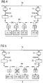
- FIG. 4 now the case of an interruption of the subnetwork NB, which is interrupted between the decentralized functional units DFE1B and DFE2B, for example due to damage to the network cable, as is sometimes the case during construction.
- each decentralized functional unit remains reachable.
- DFE1B remains on the communication network 20 and the network access point 8 on the transport network OTN; for all other decentralized functional units DFE2B to DFEnB the connection via the communication unit 22 and the network access point 10 remains.
- FIG. 5 the failure of a switching computer SU.
- the decentralized functional unit DFE2B is now disconnected from the transport network OTN if the switching computer SU has not been made redundant.
- this error has no effect, which is to be indicated by the arrows for the data telegrams DT, which extend in both directions
Landscapes
- Engineering & Computer Science (AREA)
- Mechanical Engineering (AREA)
- Computer Networks & Wireless Communication (AREA)
- Signal Processing (AREA)
- Small-Scale Networks (AREA)
- Train Traffic Observation, Control, And Security (AREA)
- Data Exchanges In Wide-Area Networks (AREA)
Claims (15)
- Dispositif (E) de commande et/ou de surveillance d'unités de fonction décentralisées (DFE) disposées le long d'un réseau de transport ferroviaire pour le trafic ferroviaire, comprenant :a) un système de commande supérieur (30) qui échange des informations avec les unités de fonction décentralisées (DFE) au moyen de télégrammes de données (DT),b) un réseau de transport de données (TN) en forme d'anneau, comprenant un nombre de points d'accès au réseau (2 à 16), le système de commande supérieur (30) étant couplé au réseau de transport de données (TN) en forme d'anneau par l'intermédiaire d'au moins un point d'accès au réseau (2, 4) ;c) des unités de communication (18 à 28) qui sont raccordées à un point d'accès au réseau (6 à 16),d) les unités de fonction décentralisées (DFE) étant regroupées en sous-groupes (A à E) avec respectivement un propre sous-réseau (NA à NE) ; ete) le sous-réseau (NA à NE) de chacun des sous-groupes (A à E) étant couplé au réseau de transport de données (TN) en forme d'anneau sur chacune de ses deux extrémités respectivement par l'intermédiaire d'une unité de communication (18 à 28) et par l'intermédiaire d'un point d'accès au réseau (6 à 16).
- Dispositif selon la revendication 1,
caractérisé en ce que
des unités de fonction surveillant le trafic et commandant le trafic peuvent être couplées au réseau de transport de données (TN) en forme d'anneau au moyen des unités de fonction décentralisées (DFE). - Dispositif selon la revendication 1 ou 2,
caractérisé en ce qu'
un premier mode de connexion est ménagé pour un sous-groupe (A, C, E) d'unités de fonction décentralisées (DFE) ayant une première densité moyenne par unité de surface de trajet et en ce qu'un deuxième mode de connexion est ménagé pour un sous-groupe (B, D) d'unités de fonction décentralisées (DFE) ayant une deuxième densité moyenne par unité de surface de trajet, la première densité moyenne étant supérieure à la deuxième densité moyenne. - Dispositif selon la revendication 3,
caractérisé en ce que
le premier mode de connexion est ménagé pour des unités de fonction décentralisées (DFE) disposées dans une zone de gare, les deux unités de communication (18, 20 ; 22, 24 ; 26, 28) et les deux points d'accès au réseau (6, 8 ; 10, 12 ; 14, 16) étant ici disposés de manière spatiale avoisinante pour le couplage du sous-réseau (A, C, E). - Dispositif selon la revendication 3,
caractérisé en ce que
le deuxième mode de connexion est ménagé pour des unités de fonction décentralisées (DFE) disposées sur un trajet libre, les deux unités de communication (20, 22 ; 24, 26) et les deux points d'accès au réseau (8, 10 ; 12, 14) étant ici disposés de manière spatiale séparée pour le couplage du sous-réseau (B, D). - Dispositif selon l'une quelconque des revendications 1 à 5,
caractérisé en ce que
le sous-réseau (NA à NE) est établi à partir d'un nombre de liaisons point-à-point d'unités de fonction décentralisées (DFE) logiquement avoisinantes. - Dispositif selon la revendication 6,
caractérisé en ce qu'
une liaison point à point est réalisée comme trajet de transmission autonome à l'intérieur d'un sous-réseau. - Dispositif selon la revendication 6 ou 7,
caractérisé en ce que
la liaison point à point est terminée à chaque extrémité par un module de commutation (SU). - Procédé de commande et/ou de surveillance d'unités de fonction décentralisées (DFE) disposées le long d'un réseau de transport ferroviaire pour le trafic ferroviaire, comprenant les étampes :a) mise à disposition d'un système de commande supérieur (30) qui échange des informations avec les unités de fonction décentralisées (DFE) au moyen de télégrammes de données (DT),b) mise à disposition d'un réseau de transport de données (TN) en forme d'anneau, comprenant un nombre de points d'accès au réseau (2 à 16) ;c) mise à disposition d'unités de communication (18 à 28) qui sont raccordées à un point d'accès au réseau (6 à 16),d) regroupement des unités de fonction décentralisées (DFE) en sous-groupes (A à E) avec respectivement un propre sous-réseau (NA à NE) ; ete) couplage au réseau de transport de données (TN) en forme d'anneau des sous-réseaux (NA à NE) de chacun des sous-groupes (A à E) sur chacune de leurs deux extrémités respectivement par l'intermédiaire d'une unité de communication (18 à 28) et par l'intermédiaire d'un point d'accès au réseau (6 à 16).
- Procédé selon la revendication 9,
caractérisé en ce que
des unités de fonction surveillant le trafic et commandant le trafic sont couplées au réseau de transport de données (TN) en forme d'anneau au moyen des unités de fonction décentralisées (DFE). - Procédé selon la revendication 9 ou 10,
caractérisé en ce qu'
un premier mode de connexion est ménagé pour un sous-groupe (A, C, E) d'unités de fonction décentralisées (DFE) ayant une première densité moyenne par unité de surface de trajet et en ce qu'un deuxième mode de connexion est ménagé pour un sous-groupe (B, D) d'unités de fonction décentralisées (DFE) ayant une deuxième densité moyenne par unité de surface de trajet, la première densité moyenne étant supérieure à la deuxième densité moyenne. - Procédé selon la revendication 11,
caractérisé en ce que
le premier mode de connexion est ménagé pour des unités de fonction décentralisées (DFE) disposées dans une zone de gare, les deux unités de communication (18, 20 ; 22, 24 ; 26, 28) et les deux points d'accès au réseau (6, 8 ; 10, 12 ; 14, 16) étant ici disposés de manière spatiale avoisinante pour le couplage du sous-réseau (A, C, E). - Procédé selon la revendication 11,
caractérisé en ce que
le deuxième mode de connexion est ménagé pour des unités de fonction décentralisées (DFE) disposées sur un trajet libre, les deux unités de communication (20, 22 ; 24, 26) et les deux points d'accès au réseau (8, 10 ; 12, 14) étant ici disposés de manière spatiale séparée pour le couplage du sous-réseau (B, D). - Procédé selon l'une quelconque des revendications 9 à 13,
caractérisé en ce que
le transport de données vers et en provenance des unités de fonction décentralisées (DFE) a lieu simultanément par l'intermédiaire des deux extrémités du sous-réseau (A à E) et en ce qu'un télégramme de données (DT) entrant d'abord sur l'unité de fonction décentralisée (DFE) et un télégramme de données (DT) entrant sur le système de commande supérieur (30) d'abord en provenance de l'unité de fonction décentralisée (DFE) sont utilisés pour le traitement ultérieur et en ce que les télégrammes de données restants sont rejetés. - Procédé selon l'une quelconque des revendications 9 à 14,
caractérisé en ce que
le transport de données vers et en provenance des unités de fonction décentralisées (DFE) est réalisé par l'intermédiaire de l'une des deux extrémités du sous-réseau, une commutation, en cas d'une défaillance de l'unité de communication et/ou du point d'accès au réseau sur cette extrémité du sous-réseau, sur un transport de données étant réalisée par l'intermédiaire de l'autre extrémité respective du sous-réseau.
Priority Applications (1)
| Application Number | Priority Date | Filing Date | Title |
|---|---|---|---|
| EP08735265.4A EP2301202B1 (fr) | 2007-05-24 | 2008-04-16 | Dispositif de commande et/ou de surveillance et de demande de données à partir d'unités de fonction décentralisées agencées le long d'un réseau de trafic |
Applications Claiming Priority (3)
| Application Number | Priority Date | Filing Date | Title |
|---|---|---|---|
| EP07010322A EP1995916A1 (fr) | 2007-05-24 | 2007-05-24 | Dispositif de commande et/ou de surveillance et de demande de données à partir d'unités de fonction décentralisées agencées le long d'un réseau de trafic |
| PCT/EP2008/003014 WO2008141706A1 (fr) | 2007-05-24 | 2008-04-16 | Dispositif de commande et/ou de surveillance et de demande de données d'unités fonctionnelles décentralisées le long d'un réseau de communication |
| EP08735265.4A EP2301202B1 (fr) | 2007-05-24 | 2008-04-16 | Dispositif de commande et/ou de surveillance et de demande de données à partir d'unités de fonction décentralisées agencées le long d'un réseau de trafic |
Publications (2)
| Publication Number | Publication Date |
|---|---|
| EP2301202A1 EP2301202A1 (fr) | 2011-03-30 |
| EP2301202B1 true EP2301202B1 (fr) | 2017-05-31 |
Family
ID=38623988
Family Applications (2)
| Application Number | Title | Priority Date | Filing Date |
|---|---|---|---|
| EP07010322A Withdrawn EP1995916A1 (fr) | 2007-05-24 | 2007-05-24 | Dispositif de commande et/ou de surveillance et de demande de données à partir d'unités de fonction décentralisées agencées le long d'un réseau de trafic |
| EP08735265.4A Active EP2301202B1 (fr) | 2007-05-24 | 2008-04-16 | Dispositif de commande et/ou de surveillance et de demande de données à partir d'unités de fonction décentralisées agencées le long d'un réseau de trafic |
Family Applications Before (1)
| Application Number | Title | Priority Date | Filing Date |
|---|---|---|---|
| EP07010322A Withdrawn EP1995916A1 (fr) | 2007-05-24 | 2007-05-24 | Dispositif de commande et/ou de surveillance et de demande de données à partir d'unités de fonction décentralisées agencées le long d'un réseau de trafic |
Country Status (4)
| Country | Link |
|---|---|
| EP (2) | EP1995916A1 (fr) |
| EA (1) | EA014950B1 (fr) |
| HU (1) | HUE035978T2 (fr) |
| WO (1) | WO2008141706A1 (fr) |
Cited By (1)
| Publication number | Priority date | Publication date | Assignee | Title |
|---|---|---|---|---|
| EP3822145A1 (fr) | 2019-11-13 | 2021-05-19 | Siemens Mobility AG | Procédé et système d'exécution d'un chemin de roulement à aiguillage projeté |
Families Citing this family (17)
| Publication number | Priority date | Publication date | Assignee | Title |
|---|---|---|---|---|
| EP2549620A3 (fr) | 2011-07-22 | 2013-04-24 | Siemens Schweiz AG | Dispositif de fonctionnement d'unités de fonction décentralisées et agencées dans une installation industrielle |
| EP2674346B1 (fr) | 2012-06-13 | 2014-12-17 | Siemens Schweiz AG | Procédé et système d'approvisionnement de puissance électrique pour des éléments de voie décentralisés d'un réseau de voies ferrées |
| DE102013208845A1 (de) | 2013-05-14 | 2014-11-20 | Siemens Aktiengesellschaft | Verfahren und Einrichtung zum Steuern und/oder zum Überwachen eines Verkehrsnetzwerks und Verkehrsnetzwerk |
| EP2821313A3 (fr) | 2013-07-02 | 2015-05-06 | Siemens Schweiz AG | Dispositif et procédé de fonctionnement d'unités fonctionnelles disposées de façon décentralisée |
| FR3025480B1 (fr) * | 2014-09-04 | 2016-12-23 | Alstom Transp Tech | Infrastructure de radiocommunication pour un systeme de signalisation ferroviaire du type cbtc |
| EP3109125A1 (fr) | 2015-06-25 | 2016-12-28 | Siemens Schweiz AG | Système et procédé d'alimentation d'unités de fonctionnement décentralisées en énergie électrique |
| EP3109128A1 (fr) | 2015-06-25 | 2016-12-28 | Siemens Schweiz AG | Système et procédé d'élimination de court-circuit dans un bus d'alimentation |
| EP3150461A1 (fr) | 2015-10-02 | 2017-04-05 | Siemens Schweiz AG | Système et procédé d'élimination automatique d'une tension induite excessive dans un bus de puissance |
| EP3176049A1 (fr) * | 2015-12-04 | 2017-06-07 | Siemens Schweiz AG | Dispositif et procédé de commande et/ou de surveillance d'unités fonctionnelles intelligentes décentralisées disposées dans un réseau de transport ferroviaire |
| DE202016102634U1 (de) * | 2016-05-18 | 2017-08-21 | Thales Deutschland Gmbh | Stromversorgungseinrichtung |
| DE102016218585A1 (de) * | 2016-09-27 | 2018-03-29 | Siemens Aktiengesellschaft | Einrichtung und Verfahren zum Betreiben von in einer Gleisanlage dezentral angeordneten Feldelementen |
| FR3056542B1 (fr) * | 2016-09-28 | 2021-09-17 | Alstom Transp Tech | Equipement de controle d'au moins un equipement a la voie d'un reseau ferroviaire et systeme ferroviaire associe |
| EP3305622A1 (fr) | 2016-10-06 | 2018-04-11 | Siemens Schweiz AG | Procédé de diagnostic de composants techniques répartis dans l'espace |
| PL3415399T3 (pl) | 2017-06-16 | 2020-04-30 | Siemens Mobility Ag | System do bezusterkowego zasilania elektrycznego urządzenia odbiorczego z redundantną magistralą energetyczną |
| CN108216275B (zh) * | 2018-01-05 | 2020-10-02 | 北京全路通信信号研究设计院集团有限公司 | 一种车载监测设备及车载监测系统 |
| EP4037126A1 (fr) | 2021-01-29 | 2022-08-03 | Siemens Mobility AG | Système de démarrage rapide commandé et de fonctionnement d'un bus à énergie redondant destiné à l'alimentation à sécurité intégrée d'un consommateur électrique |
| EP4160845B1 (fr) | 2021-09-29 | 2024-04-17 | Siemens Mobility AG | Système de démarrage contrôlé et de fonctionnement d'un bus d'énergie redondant |
Family Cites Families (6)
| Publication number | Priority date | Publication date | Assignee | Title |
|---|---|---|---|---|
| DE2402932C2 (de) * | 1974-01-22 | 1982-06-16 | Standard Elektrik Lorenz Ag, 7000 Stuttgart | Einrichtung zur linienförmigen Fahrzeugbeeinflussung |
| US5218604A (en) * | 1990-08-31 | 1993-06-08 | Bell Communications Research, Inc. | Dual-hubbed arrangement to provide a protected ring interconnection |
| US6061335A (en) * | 1997-07-24 | 2000-05-09 | At&T Corp | Method for designing SONET ring networks suitable for local access |
| JP2000004248A (ja) * | 1998-03-30 | 2000-01-07 | Toshiba Corp | 通信ネットワ―クシステム |
| JP2001151114A (ja) * | 1999-11-30 | 2001-06-05 | Hitachi Ltd | 鉄道運行管理システム |
| JP4848132B2 (ja) * | 2005-03-31 | 2011-12-28 | 東日本旅客鉄道株式会社 | 信号制御システム、信号機器及びプログラム |
-
2007
- 2007-05-24 EP EP07010322A patent/EP1995916A1/fr not_active Withdrawn
-
2008
- 2008-04-16 EP EP08735265.4A patent/EP2301202B1/fr active Active
- 2008-04-16 EA EA200971094A patent/EA014950B1/ru not_active IP Right Cessation
- 2008-04-16 HU HUE08735265A patent/HUE035978T2/hu unknown
- 2008-04-16 WO PCT/EP2008/003014 patent/WO2008141706A1/fr active Application Filing
Cited By (1)
| Publication number | Priority date | Publication date | Assignee | Title |
|---|---|---|---|---|
| EP3822145A1 (fr) | 2019-11-13 | 2021-05-19 | Siemens Mobility AG | Procédé et système d'exécution d'un chemin de roulement à aiguillage projeté |
Also Published As
| Publication number | Publication date |
|---|---|
| EP2301202A1 (fr) | 2011-03-30 |
| WO2008141706A1 (fr) | 2008-11-27 |
| EA200971094A1 (ru) | 2010-04-30 |
| EA014950B1 (ru) | 2011-04-29 |
| EP1995916A1 (fr) | 2008-11-26 |
| HUE035978T2 (hu) | 2018-05-28 |
Similar Documents
| Publication | Publication Date | Title |
|---|---|---|
| EP2301202B1 (fr) | Dispositif de commande et/ou de surveillance et de demande de données à partir d'unités de fonction décentralisées agencées le long d'un réseau de trafic | |
| EP2735082B1 (fr) | Dispositif permettant de faire fonctionner des unités fonctionnelles décentralisées disposées dans une infrastructure ferroviaire | |
| EP1062787B1 (fr) | Reseau local, notamment reseau ethernet, ayant des proprietes de redondance et un gestionnaire de redondance | |
| EP2821313A2 (fr) | Dispositif et procédé de fonctionnement d'unités fonctionnelles disposées de façon décentralisée | |
| EP2057056B1 (fr) | Procédé et dispositif destinés à un système adaptatif modulaire de commande et de contrôle d'installations de sécurisation de chemin de fer | |
| EP2594054B1 (fr) | Appareil de transport de transmission de données par câble entre deux véhicules reliés amovible l'un à l'autre | |
| DE10047923C2 (de) | Verfahren zur Erzeugung einer Verbindungs-Redundanz für ein serielles Kommunikationssystem mit einer Mastereinheit und einer Mehrzahl von Slaveeinheiten, die untereinander als Aneinanderreihung von Punkt-zu-Punkt-Verbindungen in Linientopologie verbunden sind, sowie korrespondierendes serielles Kommunikationssystem | |
| DE4090614C2 (de) | Netzwerk vom Doppelbustyp | |
| DE69316279T2 (de) | Vorrichtung zum Verbinden eines Terminals an ein mindestens aus einem Ring bestehendes lokales Netz | |
| DE19681134B4 (de) | Kommunikationssystem | |
| DE2701925A1 (de) | Fahrzeugsteuerungssystem mit hoher zuverlaessigkeit | |
| EP3415399B1 (fr) | Système d'alimentation à sureté intégrée d'un consommateur électrique à l'aide d'un bus d'énergie redondant | |
| EP4385175A1 (fr) | Système de communication et procédé de communication utilisant un message d'état | |
| DE10336022B4 (de) | Verfahren zur flexiblen Zuweisung von Verantwortlichkeiten von Streckenzentralen | |
| DE102006060222B4 (de) | Redundante Ethernet-Verbindung | |
| EP2613476B1 (fr) | Procédé de redondance pour un réseau de données spécialisé | |
| DE4242438A1 (de) | Verfahren zur Ausnutzung der Redundanz bei Datenringen in Doppelringtopologie | |
| WO2017092911A1 (fr) | Dispositif et procédé de commande et/ou de surveillance d'unités fonctionnelles intelligentes décentralisées agencées dans un réseau ferroviaire | |
| EP0645911A2 (fr) | Réseau de communication hiérarchique | |
| EP1860829A1 (fr) | Méchanisme de contournement pour des connecteurs d'un réseau dans un train | |
| WO2013143592A1 (fr) | Procédé et dispositif de transmission redondante de données critiques dans le temps | |
| DE3303862C2 (de) | Datenübertragungseinrichtung | |
| DE19714761A1 (de) | Datenkommunikationsverbindung in hierarchischem Kommunikationsnetz mit Bus, die nach einem Abfrage/Antwort-Protokoll, dem sogenannten Polling-Protokoll, betrieben wird | |
| DE3436845C2 (fr) | ||
| EP3842318A1 (fr) | Procédé de transmission de données dans un système de trafic ferroviaire, système de transmission de données, système de trafic ferroviaire doté d'un système de transmission de données et utilisation d'unités de communication sur des éléments de champ |
Legal Events
| Date | Code | Title | Description |
|---|---|---|---|
| PUAI | Public reference made under article 153(3) epc to a published international application that has entered the european phase |
Free format text: ORIGINAL CODE: 0009012 |
|
| 17P | Request for examination filed |
Effective date: 20100825 |
|
| AK | Designated contracting states |
Kind code of ref document: A1 Designated state(s): AT BE BG CH CY CZ DE DK EE ES FI FR GB GR HR HU IE IS IT LI LT LU LV MC MT NL NO PL PT RO SE SI SK TR |
|
| AX | Request for extension of the european patent |
Extension state: AL BA MK RS |
|
| DAX | Request for extension of the european patent (deleted) | ||
| D18D | Application deemed to be withdrawn (deleted) | ||
| 17Q | First examination report despatched |
Effective date: 20140701 |
|
| GRAP | Despatch of communication of intention to grant a patent |
Free format text: ORIGINAL CODE: EPIDOSNIGR1 |
|
| STAA | Information on the status of an ep patent application or granted ep patent |
Free format text: STATUS: GRANT OF PATENT IS INTENDED |
|
| RIC1 | Information provided on ipc code assigned before grant |
Ipc: B61L 27/00 20060101ALI20161024BHEP Ipc: B61L 19/00 20060101ALI20161024BHEP Ipc: B61L 19/06 20060101ALI20161024BHEP Ipc: H04L 12/46 20060101ALI20161024BHEP Ipc: H04L 12/437 20060101ALI20161024BHEP Ipc: H04L 12/43 20060101AFI20161024BHEP Ipc: B61L 21/04 20060101ALI20161024BHEP |
|
| INTG | Intention to grant announced |
Effective date: 20161111 |
|
| GRAS | Grant fee paid |
Free format text: ORIGINAL CODE: EPIDOSNIGR3 |
|
| GRAA | (expected) grant |
Free format text: ORIGINAL CODE: 0009210 |
|
| STAA | Information on the status of an ep patent application or granted ep patent |
Free format text: STATUS: THE PATENT HAS BEEN GRANTED |
|
| AK | Designated contracting states |
Kind code of ref document: B1 Designated state(s): AT BE BG CH CY CZ DE DK EE ES FI FR GB GR HR HU IE IS IT LI LT LU LV MC MT NL NO PL PT RO SE SI SK TR |
|
| REG | Reference to a national code |
Ref country code: CH Ref legal event code: EP Ref country code: GB Ref legal event code: FG4D Free format text: NOT ENGLISH Ref country code: CH Ref legal event code: NV Representative=s name: SIEMENS SCHWEIZ AG, CH |
|
| REG | Reference to a national code |
Ref country code: AT Ref legal event code: REF Ref document number: 898341 Country of ref document: AT Kind code of ref document: T Effective date: 20170615 |
|
| REG | Reference to a national code |
Ref country code: IE Ref legal event code: FG4D Free format text: LANGUAGE OF EP DOCUMENT: GERMAN |
|
| REG | Reference to a national code |
Ref country code: DE Ref legal event code: R096 Ref document number: 502008015351 Country of ref document: DE |
|
| REG | Reference to a national code |
Ref country code: NL Ref legal event code: MP Effective date: 20170531 |
|
| REG | Reference to a national code |
Ref country code: LT Ref legal event code: MG4D |
|
| REG | Reference to a national code |
Ref country code: NO Ref legal event code: T2 Effective date: 20170531 |
|
| PG25 | Lapsed in a contracting state [announced via postgrant information from national office to epo] |
Ref country code: LT Free format text: LAPSE BECAUSE OF FAILURE TO SUBMIT A TRANSLATION OF THE DESCRIPTION OR TO PAY THE FEE WITHIN THE PRESCRIBED TIME-LIMIT Effective date: 20170531 Ref country code: FI Free format text: LAPSE BECAUSE OF FAILURE TO SUBMIT A TRANSLATION OF THE DESCRIPTION OR TO PAY THE FEE WITHIN THE PRESCRIBED TIME-LIMIT Effective date: 20170531 Ref country code: HR Free format text: LAPSE BECAUSE OF FAILURE TO SUBMIT A TRANSLATION OF THE DESCRIPTION OR TO PAY THE FEE WITHIN THE PRESCRIBED TIME-LIMIT Effective date: 20170531 Ref country code: ES Free format text: LAPSE BECAUSE OF FAILURE TO SUBMIT A TRANSLATION OF THE DESCRIPTION OR TO PAY THE FEE WITHIN THE PRESCRIBED TIME-LIMIT Effective date: 20170531 Ref country code: GR Free format text: LAPSE BECAUSE OF FAILURE TO SUBMIT A TRANSLATION OF THE DESCRIPTION OR TO PAY THE FEE WITHIN THE PRESCRIBED TIME-LIMIT Effective date: 20170901 |
|
| PG25 | Lapsed in a contracting state [announced via postgrant information from national office to epo] |
Ref country code: LV Free format text: LAPSE BECAUSE OF FAILURE TO SUBMIT A TRANSLATION OF THE DESCRIPTION OR TO PAY THE FEE WITHIN THE PRESCRIBED TIME-LIMIT Effective date: 20170531 Ref country code: IS Free format text: LAPSE BECAUSE OF FAILURE TO SUBMIT A TRANSLATION OF THE DESCRIPTION OR TO PAY THE FEE WITHIN THE PRESCRIBED TIME-LIMIT Effective date: 20170930 Ref country code: BG Free format text: LAPSE BECAUSE OF FAILURE TO SUBMIT A TRANSLATION OF THE DESCRIPTION OR TO PAY THE FEE WITHIN THE PRESCRIBED TIME-LIMIT Effective date: 20170831 Ref country code: NL Free format text: LAPSE BECAUSE OF FAILURE TO SUBMIT A TRANSLATION OF THE DESCRIPTION OR TO PAY THE FEE WITHIN THE PRESCRIBED TIME-LIMIT Effective date: 20170531 Ref country code: SE Free format text: LAPSE BECAUSE OF FAILURE TO SUBMIT A TRANSLATION OF THE DESCRIPTION OR TO PAY THE FEE WITHIN THE PRESCRIBED TIME-LIMIT Effective date: 20170531 |
|
| PG25 | Lapsed in a contracting state [announced via postgrant information from national office to epo] |
Ref country code: RO Free format text: LAPSE BECAUSE OF FAILURE TO SUBMIT A TRANSLATION OF THE DESCRIPTION OR TO PAY THE FEE WITHIN THE PRESCRIBED TIME-LIMIT Effective date: 20170531 Ref country code: SK Free format text: LAPSE BECAUSE OF FAILURE TO SUBMIT A TRANSLATION OF THE DESCRIPTION OR TO PAY THE FEE WITHIN THE PRESCRIBED TIME-LIMIT Effective date: 20170531 Ref country code: CZ Free format text: LAPSE BECAUSE OF FAILURE TO SUBMIT A TRANSLATION OF THE DESCRIPTION OR TO PAY THE FEE WITHIN THE PRESCRIBED TIME-LIMIT Effective date: 20170531 Ref country code: DK Free format text: LAPSE BECAUSE OF FAILURE TO SUBMIT A TRANSLATION OF THE DESCRIPTION OR TO PAY THE FEE WITHIN THE PRESCRIBED TIME-LIMIT Effective date: 20170531 Ref country code: EE Free format text: LAPSE BECAUSE OF FAILURE TO SUBMIT A TRANSLATION OF THE DESCRIPTION OR TO PAY THE FEE WITHIN THE PRESCRIBED TIME-LIMIT Effective date: 20170531 |
|
| PG25 | Lapsed in a contracting state [announced via postgrant information from national office to epo] |
Ref country code: IT Free format text: LAPSE BECAUSE OF FAILURE TO SUBMIT A TRANSLATION OF THE DESCRIPTION OR TO PAY THE FEE WITHIN THE PRESCRIBED TIME-LIMIT Effective date: 20170531 Ref country code: PL Free format text: LAPSE BECAUSE OF FAILURE TO SUBMIT A TRANSLATION OF THE DESCRIPTION OR TO PAY THE FEE WITHIN THE PRESCRIBED TIME-LIMIT Effective date: 20170531 |
|
| REG | Reference to a national code |
Ref country code: DE Ref legal event code: R097 Ref document number: 502008015351 Country of ref document: DE |
|
| PLBE | No opposition filed within time limit |
Free format text: ORIGINAL CODE: 0009261 |
|
| STAA | Information on the status of an ep patent application or granted ep patent |
Free format text: STATUS: NO OPPOSITION FILED WITHIN TIME LIMIT |
|
| REG | Reference to a national code |
Ref country code: FR Ref legal event code: PLFP Year of fee payment: 11 |
|
| 26N | No opposition filed |
Effective date: 20180301 |
|
| REG | Reference to a national code |
Ref country code: HU Ref legal event code: AG4A Ref document number: E035978 Country of ref document: HU |
|
| PG25 | Lapsed in a contracting state [announced via postgrant information from national office to epo] |
Ref country code: SI Free format text: LAPSE BECAUSE OF FAILURE TO SUBMIT A TRANSLATION OF THE DESCRIPTION OR TO PAY THE FEE WITHIN THE PRESCRIBED TIME-LIMIT Effective date: 20170531 |
|
| PG25 | Lapsed in a contracting state [announced via postgrant information from national office to epo] |
Ref country code: MT Free format text: LAPSE BECAUSE OF FAILURE TO SUBMIT A TRANSLATION OF THE DESCRIPTION OR TO PAY THE FEE WITHIN THE PRESCRIBED TIME-LIMIT Effective date: 20170531 |
|
| PG25 | Lapsed in a contracting state [announced via postgrant information from national office to epo] |
Ref country code: MC Free format text: LAPSE BECAUSE OF FAILURE TO SUBMIT A TRANSLATION OF THE DESCRIPTION OR TO PAY THE FEE WITHIN THE PRESCRIBED TIME-LIMIT Effective date: 20170531 |
|
| REG | Reference to a national code |
Ref country code: IE Ref legal event code: MM4A |
|
| PG25 | Lapsed in a contracting state [announced via postgrant information from national office to epo] |
Ref country code: LU Free format text: LAPSE BECAUSE OF NON-PAYMENT OF DUE FEES Effective date: 20180416 |
|
| REG | Reference to a national code |
Ref country code: CH Ref legal event code: PUE Owner name: SIEMENS MOBILITY AG, CH Free format text: FORMER OWNER: SIEMENS SCHWEIZ AG, CH |
|
| PG25 | Lapsed in a contracting state [announced via postgrant information from national office to epo] |
Ref country code: IE Free format text: LAPSE BECAUSE OF NON-PAYMENT OF DUE FEES Effective date: 20180416 |
|
| REG | Reference to a national code |
Ref country code: DE Ref legal event code: R082 Ref document number: 502008015351 Country of ref document: DE Representative=s name: MAIER, DANIEL OLIVER, DIPL.-ING. UNIV., DE Ref country code: DE Ref legal event code: R081 Ref document number: 502008015351 Country of ref document: DE Owner name: SIEMENS MOBILITY AG, CH Free format text: FORMER OWNER: SIEMENS SCHWEIZ AG, ZUERICH, CH |
|
| REG | Reference to a national code |
Ref country code: GB Ref legal event code: 732E Free format text: REGISTERED BETWEEN 20190509 AND 20190515 |
|
| REG | Reference to a national code |
Ref country code: AT Ref legal event code: PC Ref document number: 898341 Country of ref document: AT Kind code of ref document: T Owner name: SIEMENS MOBILITY AG, CH Effective date: 20190612 |
|
| PGFP | Annual fee paid to national office [announced via postgrant information from national office to epo] |
Ref country code: FR Payment date: 20190425 Year of fee payment: 12 |
|
| PGFP | Annual fee paid to national office [announced via postgrant information from national office to epo] |
Ref country code: GB Payment date: 20190617 Year of fee payment: 13 |
|
| REG | Reference to a national code |
Ref country code: NO Ref legal event code: CHAD Owner name: SIEMENS MOBILITY AG, CH |
|
| REG | Reference to a national code |
Ref country code: BE Ref legal event code: PD Owner name: SIEMENS MOBILITY AG; CH Free format text: DETAILS ASSIGNMENT: CHANGE OF OWNER(S), CESSION; FORMER OWNER NAME: SIEMENS SCHWEIZ AG Effective date: 20191022 |
|
| REG | Reference to a national code |
Ref country code: HU Ref legal event code: FH1C Free format text: FORMER REPRESENTATIVE(S): SBGK SZABADALMI UEGYVIVOEI IRODA, HU Representative=s name: SBGK SZABADALMI UEGYVIVOEI IRODA, HU Ref country code: HU Ref legal event code: GB9C Owner name: SIEMENS MOBILITY AG, CH Free format text: FORMER OWNER(S): SIEMENS SCHWEIZ AG, CH |
|
| PG25 | Lapsed in a contracting state [announced via postgrant information from national office to epo] |
Ref country code: TR Free format text: LAPSE BECAUSE OF FAILURE TO SUBMIT A TRANSLATION OF THE DESCRIPTION OR TO PAY THE FEE WITHIN THE PRESCRIBED TIME-LIMIT Effective date: 20170531 |
|
| PG25 | Lapsed in a contracting state [announced via postgrant information from national office to epo] |
Ref country code: PT Free format text: LAPSE BECAUSE OF FAILURE TO SUBMIT A TRANSLATION OF THE DESCRIPTION OR TO PAY THE FEE WITHIN THE PRESCRIBED TIME-LIMIT Effective date: 20170531 |
|
| PG25 | Lapsed in a contracting state [announced via postgrant information from national office to epo] |
Ref country code: CY Free format text: LAPSE BECAUSE OF FAILURE TO SUBMIT A TRANSLATION OF THE DESCRIPTION OR TO PAY THE FEE WITHIN THE PRESCRIBED TIME-LIMIT Effective date: 20170531 |
|
| PG25 | Lapsed in a contracting state [announced via postgrant information from national office to epo] |
Ref country code: FR Free format text: LAPSE BECAUSE OF NON-PAYMENT OF DUE FEES Effective date: 20200430 |
|
| GBPC | Gb: european patent ceased through non-payment of renewal fee |
Effective date: 20200416 |
|
| PG25 | Lapsed in a contracting state [announced via postgrant information from national office to epo] |
Ref country code: GB Free format text: LAPSE BECAUSE OF NON-PAYMENT OF DUE FEES Effective date: 20200416 |
|
| PGFP | Annual fee paid to national office [announced via postgrant information from national office to epo] |
Ref country code: NO Payment date: 20220411 Year of fee payment: 15 Ref country code: HU Payment date: 20220617 Year of fee payment: 15 |
|
| PGFP | Annual fee paid to national office [announced via postgrant information from national office to epo] |
Ref country code: BE Payment date: 20220421 Year of fee payment: 15 Ref country code: AT Payment date: 20220307 Year of fee payment: 15 |
|
| PGFP | Annual fee paid to national office [announced via postgrant information from national office to epo] |
Ref country code: CH Payment date: 20230720 Year of fee payment: 16 |
|
| REG | Reference to a national code |
Ref country code: NO Ref legal event code: MMEP |
|
| REG | Reference to a national code |
Ref country code: AT Ref legal event code: MM01 Ref document number: 898341 Country of ref document: AT Kind code of ref document: T Effective date: 20230416 |
|
| REG | Reference to a national code |
Ref country code: BE Ref legal event code: MM Effective date: 20230430 |
|
| PG25 | Lapsed in a contracting state [announced via postgrant information from national office to epo] |
Ref country code: NO Free format text: LAPSE BECAUSE OF NON-PAYMENT OF DUE FEES Effective date: 20230430 Ref country code: HU Free format text: LAPSE BECAUSE OF NON-PAYMENT OF DUE FEES Effective date: 20230417 Ref country code: AT Free format text: LAPSE BECAUSE OF NON-PAYMENT OF DUE FEES Effective date: 20230416 |
|
| PG25 | Lapsed in a contracting state [announced via postgrant information from national office to epo] |
Ref country code: BE Free format text: LAPSE BECAUSE OF NON-PAYMENT OF DUE FEES Effective date: 20230430 |
|
| PGFP | Annual fee paid to national office [announced via postgrant information from national office to epo] |
Ref country code: DE Payment date: 20240619 Year of fee payment: 17 |