EP2299332A2 - Entwicklertransportvorrichtung und Bilderzeugungsvorrichtung - Google Patents
Entwicklertransportvorrichtung und Bilderzeugungsvorrichtung Download PDFInfo
- Publication number
- EP2299332A2 EP2299332A2 EP10167706A EP10167706A EP2299332A2 EP 2299332 A2 EP2299332 A2 EP 2299332A2 EP 10167706 A EP10167706 A EP 10167706A EP 10167706 A EP10167706 A EP 10167706A EP 2299332 A2 EP2299332 A2 EP 2299332A2
- Authority
- EP
- European Patent Office
- Prior art keywords
- transporting path
- transporting
- rotation
- opening
- path
- Prior art date
- Legal status (The legal status is an assumption and is not a legal conclusion. Google has not performed a legal analysis and makes no representation as to the accuracy of the status listed.)
- Withdrawn
Links
- 239000000843 powder Substances 0.000 claims abstract description 47
- 238000007789 sealing Methods 0.000 claims abstract description 27
- 230000000903 blocking effect Effects 0.000 claims abstract description 21
- 238000012546 transfer Methods 0.000 claims description 48
- 230000032258 transport Effects 0.000 claims description 4
- 230000005489 elastic deformation Effects 0.000 claims description 2
- 238000007599 discharging Methods 0.000 description 13
- 238000012545 processing Methods 0.000 description 10
- 229920002799 BoPET Polymers 0.000 description 8
- 239000005041 Mylar™ Substances 0.000 description 8
- 239000003086 colorant Substances 0.000 description 6
- 230000005484 gravity Effects 0.000 description 4
- 238000010438 heat treatment Methods 0.000 description 3
- 230000009471 action Effects 0.000 description 2
- 230000005540 biological transmission Effects 0.000 description 2
- 238000004140 cleaning Methods 0.000 description 2
- 230000008878 coupling Effects 0.000 description 2
- 238000010168 coupling process Methods 0.000 description 2
- 238000005859 coupling reaction Methods 0.000 description 2
- 238000000034 method Methods 0.000 description 2
- 238000012986 modification Methods 0.000 description 2
- 230000004048 modification Effects 0.000 description 2
- 238000000926 separation method Methods 0.000 description 2
- 150000001875 compounds Chemical class 0.000 description 1
- 230000001276 controlling effect Effects 0.000 description 1
- 230000003247 decreasing effect Effects 0.000 description 1
- 238000011161 development Methods 0.000 description 1
- 230000002708 enhancing effect Effects 0.000 description 1
- 238000003780 insertion Methods 0.000 description 1
- 230000037431 insertion Effects 0.000 description 1
- 238000007689 inspection Methods 0.000 description 1
- 238000012423 maintenance Methods 0.000 description 1
- 230000007246 mechanism Effects 0.000 description 1
- 230000002035 prolonged effect Effects 0.000 description 1
- 230000001105 regulatory effect Effects 0.000 description 1
- 230000008439 repair process Effects 0.000 description 1
- 239000000126 substance Substances 0.000 description 1
Images





Classifications
-
- G—PHYSICS
- G03—PHOTOGRAPHY; CINEMATOGRAPHY; ANALOGOUS TECHNIQUES USING WAVES OTHER THAN OPTICAL WAVES; ELECTROGRAPHY; HOLOGRAPHY
- G03G—ELECTROGRAPHY; ELECTROPHOTOGRAPHY; MAGNETOGRAPHY
- G03G15/00—Apparatus for electrographic processes using a charge pattern
- G03G15/06—Apparatus for electrographic processes using a charge pattern for developing
- G03G15/08—Apparatus for electrographic processes using a charge pattern for developing using a solid developer, e.g. powder developer
- G03G15/0822—Arrangements for preparing, mixing, supplying or dispensing developer
- G03G15/0877—Arrangements for metering and dispensing developer from a developer cartridge into the development unit
- G03G15/0881—Sealing of developer cartridges
- G03G15/0886—Sealing of developer cartridges by mechanical means, e.g. shutter, plug
-
- G—PHYSICS
- G03—PHOTOGRAPHY; CINEMATOGRAPHY; ANALOGOUS TECHNIQUES USING WAVES OTHER THAN OPTICAL WAVES; ELECTROGRAPHY; HOLOGRAPHY
- G03G—ELECTROGRAPHY; ELECTROPHOTOGRAPHY; MAGNETOGRAPHY
- G03G15/00—Apparatus for electrographic processes using a charge pattern
- G03G15/06—Apparatus for electrographic processes using a charge pattern for developing
- G03G15/08—Apparatus for electrographic processes using a charge pattern for developing using a solid developer, e.g. powder developer
- G03G15/0822—Arrangements for preparing, mixing, supplying or dispensing developer
- G03G15/0877—Arrangements for metering and dispensing developer from a developer cartridge into the development unit
-
- G—PHYSICS
- G03—PHOTOGRAPHY; CINEMATOGRAPHY; ANALOGOUS TECHNIQUES USING WAVES OTHER THAN OPTICAL WAVES; ELECTROGRAPHY; HOLOGRAPHY
- G03G—ELECTROGRAPHY; ELECTROPHOTOGRAPHY; MAGNETOGRAPHY
- G03G15/00—Apparatus for electrographic processes using a charge pattern
- G03G15/06—Apparatus for electrographic processes using a charge pattern for developing
- G03G15/08—Apparatus for electrographic processes using a charge pattern for developing using a solid developer, e.g. powder developer
- G03G15/0822—Arrangements for preparing, mixing, supplying or dispensing developer
- G03G15/0877—Arrangements for metering and dispensing developer from a developer cartridge into the development unit
- G03G15/0879—Arrangements for metering and dispensing developer from a developer cartridge into the development unit for dispensing developer from a developer cartridge not directly attached to the development unit
-
- G—PHYSICS
- G03—PHOTOGRAPHY; CINEMATOGRAPHY; ANALOGOUS TECHNIQUES USING WAVES OTHER THAN OPTICAL WAVES; ELECTROGRAPHY; HOLOGRAPHY
- G03G—ELECTROGRAPHY; ELECTROPHOTOGRAPHY; MAGNETOGRAPHY
- G03G2215/00—Apparatus for electrophotographic processes
- G03G2215/06—Developing structures, details
- G03G2215/066—Toner cartridge or other attachable and detachable container for supplying developer material to replace the used material
- G03G2215/0692—Toner cartridge or other attachable and detachable container for supplying developer material to replace the used material using a slidable sealing member, e.g. shutter
Definitions
- the present invention relates to a powder transporting device and an image forming apparatus.
- JP-A-2000-221766 is known as a technique capable of attaching and removing a transporting path for a powder.
- a lower end of a transporting path tube (43) extended from a toner supplying device (40) and serving to transport a powder and an upper end of a toner receiving tube (17) extended from a developing device (14) can be attached and removed depending on an insertion in a longitudinal direction of the developing device (14), and a double shutter component (5) is supported on the lower end of the transporting path tube (43).
- the double shutter (5) has an oscillating type gate plate (6) which is rotatably engaged with a rear side of the lower end of the transporting path tube (43), a sliding type gate plate (7) which is disposed on the rear side of the transporting path tube (43), is provided in contact with a lower surface of the oscillating type gate plate (6) and is movable in a longitudinal direction, and a spring (8) for energizing the sliding type gate plate (7) forward.
- the toner receiving tube (17) is moved forward (C)
- the sliding type gate plate (7) is pushed forward (C) in contact with the lower surface of the oscillating type gate plate (6) inclined obliquely and forward by means of the spring (8).
- a longitudinal direction is set to be an X-axis direction
- a transverse direction is set to be a Y-axis direction
- a vertical direction is set to be a Z-axis direction
- directions or sides indicated as arrows X, -X, Y, -Y, Z and -Z are set to be forward, rearward, rightward, leftward, upward and downward directions or front, rear, right, left, upper and lower sides, respectively.
- Fig. 1 is an explanatory view showing a whole image forming apparatus according to a first example of the invention.
- an image forming apparatus U has a user interface UI according to an example of an operating portion, an image input device U1 according to an example of an image information input device, a paper feeding device U2, an image forming apparatus body U3, and a paper processing device U4.
- the user interface UI has input keys according to an example of input buttons such as a copy start key according to an example of a copy start button, a copy number set key according to an example of a copy number set button, and a numerical keypad according to an example of a numeral input button, and a display unit UI1.
- the image input device U1 is constituted by an image scanner according to an example of an automatic original transporting device and an image reading device.
- the image input device U1 reads an original which is not shown and converts the original into image information, and inputs the image information to the image forming apparatus body U3.
- the paper feeding device U2 has paper feeding trays TR1 to TR4 according to an example of plural of paper feeding portions, and a paper feeding path SH1 for taking out a recording paper S according to an example of a medium which is accommodated in each of the paper feeding trays TR1 to TR4 and transporting the recording paper S to the image forming apparatus body U3.
- the image forming apparatus body U3 has an image recording portion for recording an image on the recording paper S transported from the paper feeding device U2, a toner dispenser device U3a according to an example of a multicolor powder supplying device, a paper transporting path SH2, a paper discharging path SH3, a paper inverting path SH4 and a paper circulating path SH6.
- the image recording portion will be described below.
- the image forming apparatus body U3 has a control portion C, a laser driving circuit D according to an example of a latent image writing device driving circuit which is to be controlled by the control portion C, and a power circuit E to be controlled by the control portion C.
- the laser driving circuit D to be controlled in an operation through the control portion C outputs laser driving signals corresponding to image information about Y : yellow, M : magenta, C : cyan and K : black input from the image input device U1 to latent image forming devices ROSy, ROSm, ROSc and ROSk for the respective colors in a predetermined timing.
- a pull-out member U3b for an image forming unit is supported below the latent image forming devices ROSy, ROSm, ROSc and ROSk for the respective colors so as to be movable between a pull-out position in which it is forward pulled out of the image forming apparatus body U3 and an attaching position in which it is attached into the image forming apparatus body U3 by means of a pair of left and right guiding members R1 and R1.
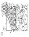
- Fig. 2 is an explanatory view showing the image forming apparatus body and the toner dispenser device.
- an image carrier unit Uk for K black has a photosensitive drum Pk according to an example of an image carrier, a charger CCk according to an example of a discharger, and a cleaner CLk according to an example of a cleaning device for an image carrier.
- the cleaner CLk is constituted by a cleaner unit.
- Image holding member units Uy, Um and Uc for the other colors Y, M and C also have photosensitive drums Py, Pm and Pc, chargers CCy, CCm and CCc, and cleaners CLy, CLm and CLc, respectively.
- the photosensitive drum Pk for the K color which is frequently used and has a surface worn greatly is constituted to have a larger diameter as compared with the photosensitive drums Py, Pm and Pc for the other colors, and is ready for a high-speed rotation and has a lifetime prolonged.
- Toner image forming members Uy+Gy, Um+Gm, Uc+Gc, and Uk+Gk are constituted by the image carrier units Uy, Um, Uc and Uk and developing units Gy, Gm, Gc and Gk according to an example of a developing device having a developing roll R0.
- the image carrier units Uy, Um, Uc and Uk and the developing units Gy, Gm, Gc and Gk are removably attached to the pull-out member U3b for the image forming unit.
- the photosensitive drums Py, Pm, Pc and Pk are uniformly charged by the chargers CCy, CCm, CCc and CCk respectively, and electrostatic latent images are then formed on surfaces thereof through laser beams Ly, Lm, Lc and Lk according to an example of latent image writing lights output from the latent image forming devices ROSy, ROSm, ROSc and ROSk.
- the electrostatic latent images formed on the surfaces of the photosensitive drums Py, Pm, Pc and Pk are developed into toner images according to an example of visible images with toners according to an example of powders for the respective colors of Y : yellow, M : magenta, C : cyan and K : black by means of the developing units Gy, Gm, Gc and Gk.
- the toner images on the surfaces of the photosensitive drums Py, Pm, Pc and Pk are sequentially superposed and transferred onto an intermediate transfer belt B according to an example of an intermediate transfer member in a primary transfer region Q3 by means of primary transfer rolls T1y, T1m, T1c and T1k according to an example of primary transfer units so that a multicolor image, that is, a color image is formed on the intermediate transfer belt B.
- the color image formed on the intermediate transfer belt B is transported to a secondary transfer region Q4.
- the toners remaining on the surfaces of the photosensitive drums Py, Pm, Pc and Pk are cleaned by the cleaners CLy, CLm, CLc and CLk for the photosensitive drums.
- the toner dispenser device U3a has toner dispensers TDy, TDm, TDc and TDk according to an example of powder supplying devices corresponding to the respective colors Y, M, C and K.
- Toner cartridges Ky, Km, Kc and Kk according to an example of powder housing containers are removably attached to the toner dispensers TDy to TDk, and the toner dispensers TDy to TDk supply powders in the toner cartridges Ky to Kk to the developing units Gy to Gk depending on a toner consumption of the developing units Gy to Gk.
- a pull-out member U3c for an intermediate transfer member is supported below the pull-out member U3b for the image forming unit so as to be movable between a pull-out position in which it is forward pulled out of the image forming apparatus body U3 and an attaching position in which it is attached into the image forming apparatus body U3.
- a belt module BM according to an example of the intermediate transfer device is supported by the pull-out member U3c for the intermediate transfer member so as to be upward and downward movable between an upward moving position in which it comes in contact with lower surfaces of the photosensitive drums Py, Pm, Pc and Pk and a downward moving position in which it is separated downward from the lower surfaces.
- the belt module BM has the intermediate transfer belt B, a belt support roll Rd+Rt+Rw+Rf+T2a according to an example of an intermediate transfer member support member, and the primary transfer rolls T1y, T1m, T1c and T1k.
- the belt support roll Rd+Rt+Rw+Rf+T2a has a belt driving roll Rd according to an example of an intermediate transfer member driving member, a tension roll Rt according to an example of a tension applying member, a walking roll Rw according to an example of a meander preventing member, plural of idler rolls Rf according to an example of a driven member, and a backup roll T2a according to an example of a secondary transfer opposing member.
- the intermediate transfer belt B is supported to be rotatable and movable in a direction of an arrow Ya by means of the belt support roll Rd+Rt+Rw+Rf+T2a.
- a secondary transfer unit Ut is disposed below the backup roll T2a.
- a secondary transfer roll T2b according to an example of a secondary transfer member of the secondary transfer unit Ut is disposed to enable a separation/contact from/with the backup roll T2a in a state in which the intermediate transfer belt B is interposed therebetween, and the secondary transfer region Q4 is formed by a region in which the secondary transfer roll T2b comes in pressure contact with the intermediate transfer belt B.
- a contact roll T2c according to an example of a voltage applying contact member abuts on the backup roll T2a, and a secondary transfer unit T2 is constituted by the rolls T2a to T2c.
- a secondary transfer voltage having the same polarity as a charging polarity of the toner is applied to the contact roll T2c at a preset time from the power circuit to be controlled by the control portion C.
- the paper transporting path SH2 is disposed below the belt module BM.
- the recording paper S fed from the paper feeding path SH1 of the paper feeding device U2 is transported to the paper transporting path SH2 and is transported to the secondary transfer region Q4 via a medium guiding member SGr and a pre-transfer medium guiding member SG1 corresponding to a time that a toner image is transported to the secondary transfer region Q4 by means of a resist roll Rr according to an example of a paper feeding time regulating member.
- the medium guiding member SGr is fixed to the image forming apparatus body U3 together with the resist roll Rr.
- the toner image on the intermediate transfer belt B is transferred onto the recording paper S by means of the secondary transfer unit T2 in a passage through the secondary transfer region Q4.
- toner images superposed and transferred primarily onto the surface of the intermediate transfer belt B are secondarily transferred onto the recording paper S in a lump.
- the intermediate transfer belt B subjected to the secondary transfer is cleaned by a belt cleaner CLB according to an example of an intermediate transfer member cleaning device.
- the secondary transfer roll T2b and the belt cleaner CLB are supported to enable a separation/contact from/with the intermediate transfer belt B.
- a transfer device T1+B+T2+CLB for transferring images on the surfaces of the photosensitive drums Py to Pk onto the recording paper S is constituted by the primary transfer rolls T1y, T1m, T1c and T1k, the intermediate transfer belt B, the secondary transfer unit T2, and the belt cleaner CLB.
- the recording paper S having the toner image transferred secondarily is transported to a fixing device F via a post-firansfer medium guiding member SG2 and a paper transporting belt BH according to an example of a pre-fixing medium transporting member.
- the fixing device F has a heating roll Fh according to an example of a heating and fixing member and a pressurizing roll Fp according to an example of a pressurizing and fixing member, and a fixing region Q5 is formed by a region in which the heating roll Fh and the pressurizing roll Fp come in pressure contact with each other.
- a transporting path switching member GT1 is provided on a downstream side of the fixing device F.
- the transporting path switching member GT1 selectively switches the recording paper S transported through the paper transporting path SH2 and heated and fixed by the fixing region Q5 into either the paper discharging path SH3 or the paper inverting path SH4 at the paper processing device U4 side.
- the recording paper S sent to the paper discharging path SH3 is transported to a paper transporting path SH5 of the paper processing device U4.
- a curl correcting device U4a according to an example of a curve correcting device is disposed in the middle of the paper transporting path SH5, and a switching gate G4 according to an example of a transporting path switching member is disposed on the paper transporting path SH5.
- the switching gate G4 transports the recording paper S sent through the paper transporting path SH3 of the image forming apparatus body U3 to a side of a first curl correcting member h1 or a second curl correcting member h2 depending on a direction of a curve, that is, a curl.
- a curl of the recording paper S transported to the first curl correcting member h1 or the second curl correcting member h2 is corrected in the passage.
- the recording paper S having the curl corrected is discharged from a discharging roll Rh according to an example of a discharging member to a discharging tray TRh according to an example of a discharging portion of the paper processing device U4 in a state in which an image fixing surface of the recording paper S is turned upward, that is, a face-up state.
- the recording paper S transported to the paper inverting path SH4 of the image forming apparatus body U3 through the transporting path switching member GT1 passes to push away a transporting direction controlling member constituted by an elastic thin film-shaped member, that is, a Mylar gate GT2 and is thus transported to the paper inverting path SH4 of the image forming apparatus body U3.
- the paper circulating path SH6 and a paper inverting path SH7 are connected to a downstream end of the paper inverting path SH4 of the image forming apparatus body U3, and a Mylar gate GT3 is also disposed in a connecting portion thereof.
- the paper transported to the paper inverting path SH4 through the switching gate GT1 passes through the Mylar gate GT3 and is thus transported to the paper inverting path SH7 side of the paper processing device U4.
- the transporting direction is controlled by the Mylar gate GT3 and the recording paper S switched back is transported to the paper circulating path SH6 side when the recording paper S transported through the paper inverting path SH4 once passes through the Mylar gate GT3 exactly and is thus transported to the paper inverting path SH7, and is then transported in a reverse direction, that is, is switched back.
- the recording paper S transported to the paper circulating path SH6 is retransmitted to the transfer region Q4 via the paper feeding path SH1.
- the transporting direction of the recording paper S is controlled by the Mylar gate GT2 and the recording paper S is transported to the paper transporting path SH5 with both sides inverted.
- a curl of the recording paper S having the both sides inverted is corrected by the curl correcting member U4a and the recording paper S can be then discharged to the paper discharging tray TRh of the paper processing device U4 in a state in which the image fixing surface of the recording paper S is turned downward, that is, a face-down state.
- a paper transporting path SH is constituted by the elements indicated as the designations SH1 to SH7.
- a paper transporting device SU is constituted by the elements indicated as the designations SH, Ra, Rr, Rh, SGr, SG1, SG2, BH, and GT1 to GT3.
- Fig. 3 is a sectional view showing the powder supplying device.
- the toner dispenser TDy has a reserve tank RTy according to an example of a storing and transporting container into which the powder of the toner cartridge Ky flows and in which the powder is stored temporarily and stirred.
- a communicating and transporting cylinder 1 extended downward is connected to a lower surface of the reserve tank RTy, and a communicating and transporting path 1a is formed in the communicating and transporting cylinder 1.
- the powder flowing from the reserve tank RTy is transported through the communicating and transporting path 1a.
- An inclined transporting cylinder 2 extended leftward, obliquely and downward is connected to a lower end of the communicating and transporting cylinder 1, and an inclined transporting path 2a is formed in the inclined transporting cylinder 2.
- a lower end of the communicating and transporting path 1a is connected to the inclined transporting path 2a.
- An auger 2b extended along the inclined transporting path 2a according to an example of a transporting member is disposed in the inclined transporting path 2a. Both upper and lower ends of the auger 2b are rotatably supported by bearing members 2c supported on both upper and lower ends of the inclined transporting path 2a. The upper end of the auger 2b penetrates upward from the upper end of the inclined transporting path 2a, and a passive gear 2d according to an example of a passive toothed wheel is supported on the upper end of the auger 2b.
- the passive gear 2d is engaged with a transmission gear 3a according to an example of a driving transmission toothed wheel which is supported on a driving rotary shaft 3 extended from the image forming apparatus body U3 side.
- An upper transporting cylinder 4 extended downward is connected to the lower end of the inclined transporting cylinder 2.
- An upper transporting path 4a according to an example of a first transporting path to be connected to the lower end of the inclined transporting path 2a is formed in the upper transporting cylinder 4.
- a connecting member 6 is supported on a lower end of the upper transporting cylinder 4.
- Fig. 4 is a perspective view for explaining the connecting member.
- Fig. 5 is a sectional view for explaining a state in which the connecting member and a lower transporting member are connected to each other.
- the connecting member 6 has a connecting frame 7 extended in a vertical direction according to an example of a connecting member frame body.
- An upper connecting portion 8 bulged like a convex part and taking a shape of an arcuate surface is formed on an upper end of the connecting frame 7.
- An upper connecting port 8a serving as a square opening to be connected to the upper transporting path 4a is formed on a central part of the upper connecting portion 8, and a connection transporting path 8b extended downward is formed therein.
- a pair of left and right spring support portions 8c taking an overhung shape toward both left and right sides according to an example of an energizing member support portion is formed on a front end of the upper connecting portion 8.
- a lower connecting portion 9 is formed on a lower end of the upper connecting portion 8.
- the lower connecting portion 9 has a connecting portion body 11 on a front side and a guiding portion 12 on a rear side.
- the connecting portion body 11 is formed to take a shape of a prism extended in the vertical direction, and a lower contact surface 11a is formed on a lower end of the connecting portion body 11.
- the lower contact surface 11a is inclined rearward and downward.
- a rotating shutter housing portion 11b is formed in the connecting portion body 11.
- the rotating shutter housing portion 11b takes an upward concave shape from the lower end.
- connection transporting path 8b is connected to the rotating shutter housing portion 11b, and the rotating shutter housing portion 11b has a larger area than a discharging port 8d serving as an opening formed on the lower end of the connection transporting path 8b.
- the guiding portion 12 has a plate-shaped guiding portion body 12a which is extended rearward from a rear end in a central part in the vertical direction of the connecting portion body 11.
- a first guide groove 12b is formed on a central part in a transverse direction of an upper surface of the guiding portion body 12a.
- the first guide groove 12b is extended in a longitudinal direction and takes a concave shape according to an example of a first open/close guiding portion.
- a pair of left and right guide rails 12c is disposed on both left and right ends of the guiding portion body 12a.
- the guide rail 12c has an upper end curved inward in the transverse direction and is extended in the longitudinal direction according to an example of a second open/close guiding portion.
- a sponge seal 13 is fixed and supported on an edge part of the discharging port 8d.
- the sponge seal 13 is formed by an elastic member according to an example of an opening sealing member.
- a seal opening 13a is formed on a central part of the sponge seal 13. The seal opening 13a is opened to take a square shape corresponding to the discharging port 8d according to an example of an elastic member opening.
- An inner shutter 14 is supported on a rear end of the shutter housing portion 11b rotatably around a rotating center 14a according to an example of a rotation gate member.
- the inner shutter 14 has a plate-shaped inner shutter body 14b according to an example of a rotation gate member body.
- plural of stripe-shaped ribs 14c protruded downward and extended in the longitudinal direction is formed on a bottom face of the inner shutter body 14b according to an example of a contact portion.
- a slide shutter 16 is supported on the guiding portion body 12a according to an example of an outer gate member.
- the slide shutter 16 is movable in the longitudinal direction.
- the slide shutter 16 has a plate-shaped slide shutter body 16a disposed below the guiding portion body 12a.
- a frame-shaped coupling portion 16b surrounding the guiding portion body 12a is integrally formed on a rear end of the slide shutter body 16a.
- the coupling portion 16b has a guide bar 16c extended in a transverse direction above the guiding portion body 12a according to an example of a guided member.
- the guide bar 16c has a pair of left and right guided concave portions 16d according to an example of a second guided portion and a guided and protruded portion 16e according to an example of a first guided portion which are formed thereon.
- the guided concave portion 16d is fitted in the guiding portion body 12c and is thus guided movably in the longitudinal direction.
- the guided and protruded portion 16e is fitted in the first guide groove 12b and is thus guided movably in the longitudinal direction.
- a pair of left and right spring support portions 16f on a guide side is formed according to an example of an energizing support portion in positions corresponding to the spring support portions 8c at both left and right ends of the guide bar 16c.
- a pair of left and right tension springs 17 extended in the longitudinal direction is coupled according to an example of an energizing member between the spring support portions 16f on the guide side and the spring support portions 8c. The tension spring 17 energizes the guide bar 16 forward.
- a lower transporting member 18 is disposed below the lower connecting portion 9.
- the lower transporting member 18 has a lower transporting cylinder 19 extended in a vertical direction and taking a cylindrical shape, and a connected portion 21 is formed on an upper end of the lower transporting cylinder 19.
- a lower transporting path 22 is formed according to an example of a second transporting path in the lower transporting cylinder 19.
- the lower transporting path 22 has a lower end connected to the developing unit Gy and an upper end connected to the connection transporting path 8b.
- a powder supplying path GH is constituted according to an example of a transporting path by the elements indicated as the designations 1a, 2a, 4a, 8b and 22.
- the connected portion 21 has a connected surface 21a which is inclined upward in a forward direction corresponding to the lower contact surface 11 a, and has a structure in which the connecting portion body 11 can be accommodated into the connected portion 21 from a rear part.
- a rectangular transporty-in port 21b is formed on a central part of the connected surface 21a. The transporty-in port 21b is extended in the longitudinal direction corresponding to the shutter housing portion 11b.
- a sponge seal 23 formed by an elastic member according to an example of a sealing member is fixedly supported on an edge part of the transporty-in port 21b.
- a lower seal port 23a is formed according to an example of an opening on a central part of the lower sponge seal 23.
- the lower seal port 23a is extended in the longitudinal direction corresponding to the transporty-in port 21 b and is opened to take a rectangular shape.
- a height of the lower sponge seal 23 according to the first example is set to be greater than that of the lower contact surface 11a.
- the lower sponge seal 23 is elastically deformed to seal a clearance between the connected portion 21 and the connecting portion body 11.
- a height of the slide shutter body 16a of the slide shutter 16 is set in such a manner that a front end comes in contact with a rear end face 23b of the lower sponge seal 23.
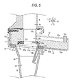
- the front end of the slide shutter body 16a comes in contact with the rear end face 23b and is thus shifted rearward against the tension spring 17 in a state in which the connected portion 21 and the connecting member body 11 are connected to each other.
- the slide shutter body 16a is held in an outer opening position in which a lower surface of the shutter housing portion 11b is opened.
- the inner shutter body 14b is rotated around the rotating center 14a by an action of a gravity and thus enters an inner part of the lower transporting path 22, and is held in a rotation opening position in which the rib 14c comes in contact with an internal wall rear surface 22a of the lower transporting path 22.
- Fig. 6 is an explanatory view showing a state in which the lower transporting member is shifted forward in the state illustrated in Fig. 5 .
- Fig. 7 is an explanatory view showing a state in which the lower transporting member is shifted further forward in the state illustrated in Fig. 6 .
- Fig. 8 is an explanatory view showing a state in which the lower transporting member is removed from the connecting member.
- the slide shutter body 16a is energized forward by means of the tension spring 17 and is forward moved while maintaining a state in which the front end comes in contact with the rear end face 23b according to the forward movement of the lower transporting member 18.
- the slide shutter 16 is moved forward while the front end comes in contact with the rear end face 23b of the lower sponge seal 23 by an energizing force of the tension spring 17, and enters a part provided below the rib 14c after the contact of the contact portion 24.
- the transporting member 18 is removed forward in the state in which the lower surface of the shutter housing portion 11b is blocked with the slide shutter 16.
- the rear end face 23b of the lower sponge seal 23 pushes the front end of the slide shutter 16 to move the slide shutter 16 to the outer opening position shown in Fig. 5 against the energizing force of the tension spring 17 when the lower transporting member 18 is moved rearward.
- the upper transporting path 4a and the lower transporting path 22 are constituted removably through the connecting member 6.
- the upper transporting path 4a and the lower transporting path 22 are constituted removably in a longitudinal direction to be a direction crossing the vertical direction in which the powder is transported through the powder supplying path GH.
- a powder transporting device U5 is constituted by members indicated as the designations 4 to 24.
- the toner dispenser device U3a when the image forming operation, that is, the job is executed so that the powder is consumed by each of the developing units Gy to Gk, the toner dispenser device U3a is operated depending on an amount of the consumption so that the powder is supplied from each of the toner cartridges Ky to Kk.
- an elastic restoring force of the sponge seal 13 acts and a force for pushing the rib 14c against the contact portion 24 acts. Therefore, the rib 14c is wiped more stably as compared with the case in which the rib 14c is not provided and the sponge seal 13 has a small elastic restoring force or no elastic restoring force, for example.
- the slide shutter 16 on which the energizing force of the tension spring 17 acts pushes the rib 14c upward to move the inner shutter 14 to the rotation blocking position, and is thus moved to the outer blocking position.
- the slide shutter 16 moved to the outer blocking position holds the inner shutter 14 pushed against the sponge seal 13 so that the seal opening 13a is blocked in a sealing state.
- the slide shutter 16 according to the first example is disposed on the outside of the upper transporting path 4a and the lower transporting path 22 in contact with the rear end face 23b in the outer opening position. Consequently, it is possible to reduce the scatter of the powder more greatly as compared with the case in which the tip of the sliding type gate plate (7) enters the inner part of the opening (91) in the opening state and the powder might be scattered from or might leak out of the clearance as described in JP-A-2000-221766 .
- the bottom face of the inner shutter 14 is wiped by the contact portion 24 and then comes in contact with the slide shutter 16 in the outer blocking position. Accordingly, it is possible to reduce the scatter of the powder more greatly as compared with the case in which the front end of the sliding type gate plate (7) is closed while wiping the lower surface of the oscillating type gate plate (6) and the powder wiped by the tip of the sliding type gate plate (7) might be dropped or scattered as described in JP-A-2000-221766 .
- the powder scattered from the clearance might be deposited on the upper surface of the sliding type gate plate (7) and might fall in the movement of the sliding type gate plate (7), furthermore, the powder is not deposited on the upper surface of the slide shutter 16 in the outer opening position and can be prevented from falling to contaminate the inner part of the image forming apparatus body U3 in the first example.
- the slide shutter 16 comes in contact with the rib 14c on the lower surface of the inner shutter 14 in the movement thereof.
- a contact area of the slide shutter 16 and the inner shutter 14 can be reduced more greatly so that a frictional resistance can be decreased more highly. Therefore, a resistance can be reduced in the movement of the slide shutter 16 between the outer blocking position and the outer opening position, and the slide shutter 16 is thus moved stably between the outer blocking position and the outer opening position.
Landscapes
- Physics & Mathematics (AREA)
- General Physics & Mathematics (AREA)
- Electrophotography Configuration And Component (AREA)
- Dry Development In Electrophotography (AREA)
- Filling Or Emptying Of Bunkers, Hoppers, And Tanks (AREA)
- Air Transport Of Granular Materials (AREA)
Applications Claiming Priority (1)
| Application Number | Priority Date | Filing Date | Title |
|---|---|---|---|
| JP2009215993A JP5370038B2 (ja) | 2009-09-17 | 2009-09-17 | 現像剤搬送装置および画像形成装置 |
Publications (2)
| Publication Number | Publication Date |
|---|---|
| EP2299332A2 true EP2299332A2 (de) | 2011-03-23 |
| EP2299332A3 EP2299332A3 (de) | 2011-05-25 |
Family
ID=42563035
Family Applications (1)
| Application Number | Title | Priority Date | Filing Date |
|---|---|---|---|
| EP10167706A Withdrawn EP2299332A3 (de) | 2009-09-17 | 2010-06-29 | Entwicklertransportvorrichtung und Bilderzeugungsvorrichtung |
Country Status (4)
| Country | Link |
|---|---|
| US (1) | US8155555B2 (de) |
| EP (1) | EP2299332A3 (de) |
| JP (1) | JP5370038B2 (de) |
| AU (1) | AU2010202615B2 (de) |
Families Citing this family (4)
| Publication number | Priority date | Publication date | Assignee | Title |
|---|---|---|---|---|
| JP4842356B2 (ja) * | 2009-09-15 | 2011-12-21 | シャープ株式会社 | トナーカートリッジおよびこれを用いる画像形成装置 |
| JP6021834B2 (ja) * | 2014-02-12 | 2016-11-09 | 京セラドキュメントソリューションズ株式会社 | トナー搬送装置、及びこれを備える画像形成装置 |
| JP6287590B2 (ja) * | 2014-05-29 | 2018-03-07 | 京セラドキュメントソリューションズ株式会社 | トナー容器、トナー補給装置、画像形成装置 |
| JP6888447B2 (ja) * | 2017-07-11 | 2021-06-16 | 株式会社リコー | 搬送装置、及び、画像形成装置 |
Citations (2)
| Publication number | Priority date | Publication date | Assignee | Title |
|---|---|---|---|---|
| JP2000221766A (ja) | 1999-02-04 | 2000-08-11 | Fuji Xerox Co Ltd | 画像形成装置 |
| JP2007070124A (ja) | 2006-11-13 | 2007-03-22 | Fuji Xerox Co Ltd | シート処理装置 |
Family Cites Families (7)
| Publication number | Priority date | Publication date | Assignee | Title |
|---|---|---|---|---|
| JPH07234620A (ja) * | 1994-02-24 | 1995-09-05 | Fuji Xerox Co Ltd | トナー回収装置 |
| JP2000098713A (ja) * | 1998-09-18 | 2000-04-07 | Fuji Xerox Co Ltd | 画像形成装置 |
| KR100694128B1 (ko) | 2005-06-20 | 2007-03-12 | 삼성전자주식회사 | 토너카트리지 및 이를 채용한 전자사진방식 화상형성장치 |
| KR101347158B1 (ko) * | 2007-01-29 | 2014-01-03 | 삼성전자주식회사 | 유로 개폐장치를 구비한 화상형성장치 |
| JP4412736B2 (ja) * | 2007-08-03 | 2010-02-10 | キヤノン株式会社 | 現像剤補給カートリッジ及び電子写真画像形成装置 |
| JP4370351B2 (ja) * | 2007-08-28 | 2009-11-25 | シャープ株式会社 | 画像形成装置 |
| JP5326392B2 (ja) * | 2007-12-25 | 2013-10-30 | 株式会社リコー | シャッタ機構、粉体供給装置、及び、画像形成装置 |
-
2009
- 2009-09-17 JP JP2009215993A patent/JP5370038B2/ja not_active Expired - Fee Related
-
2010
- 2010-06-18 US US12/818,818 patent/US8155555B2/en not_active Expired - Fee Related
- 2010-06-23 AU AU2010202615A patent/AU2010202615B2/en active Active
- 2010-06-29 EP EP10167706A patent/EP2299332A3/de not_active Withdrawn
Patent Citations (2)
| Publication number | Priority date | Publication date | Assignee | Title |
|---|---|---|---|---|
| JP2000221766A (ja) | 1999-02-04 | 2000-08-11 | Fuji Xerox Co Ltd | 画像形成装置 |
| JP2007070124A (ja) | 2006-11-13 | 2007-03-22 | Fuji Xerox Co Ltd | シート処理装置 |
Also Published As
| Publication number | Publication date |
|---|---|
| AU2010202615B2 (en) | 2012-05-17 |
| EP2299332A3 (de) | 2011-05-25 |
| JP2011064968A (ja) | 2011-03-31 |
| US8155555B2 (en) | 2012-04-10 |
| US20110064474A1 (en) | 2011-03-17 |
| AU2010202615A1 (en) | 2011-03-31 |
| JP5370038B2 (ja) | 2013-12-18 |
Similar Documents
| Publication | Publication Date | Title |
|---|---|---|
| KR101030555B1 (ko) | 수용 용기 및 화상 형성 장치 | |
| US8126373B2 (en) | Toner supply device and image forming apparatus that prevents toner from being scattered from the device | |
| KR100868309B1 (ko) | 화상 형성 장치용 현상제 용기 | |
| CN101430523B (zh) | 调色剂补给装置、图像形成装置及彩色图像形成装置 | |
| AU2008202211A1 (en) | Image forming apparatus and detachable body | |
| US8554117B2 (en) | Toner cartridge with shutter opening/closing and image forming apparatus using the same | |
| JP4811490B2 (ja) | 現像剤回収装置および画像形成装置 | |
| US8781375B2 (en) | Powder container, powder conveying apparatus, and image forming apparatus | |
| EP2299332A2 (de) | Entwicklertransportvorrichtung und Bilderzeugungsvorrichtung | |
| WO2016164659A2 (en) | Toner inlet port alignment features for a developer unit of an electrophotographic image forming device | |
| JP2007212766A (ja) | トナー補給装置、トナー補給ボックス、及び中継ボックス | |
| JP6818413B2 (ja) | 画像形成装置 | |
| JP5218124B2 (ja) | 現像剤供給装置及び画像形成装置 | |
| JPH08328337A (ja) | 画像形成装置 | |
| CN110874032A (zh) | 显影剂收容构件以及图像形成装置 | |
| US7676183B2 (en) | Toner supply device and developing unit using the same for use in an image forming apparatus for performing image formation with toner | |
| KR20080088367A (ko) | 현상제 반송 부재, 현상제 수용기, 화상 형성 장치 및현상제 반송 부재 조립 방법 | |
| JP2013145317A (ja) | 現像ユニット、プロセスカートリッジ、画像形成装置および現像剤補給方法 | |
| JP2000066500A (ja) | 現像装置 | |
| JP2018031968A (ja) | プロセスカートリッジ及び画像形成装置 | |
| JP6942950B2 (ja) | 画像形成装置 | |
| JP3613031B2 (ja) | 現像装置 | |
| JP6972836B2 (ja) | 粉体処理装置および画像形成装置 | |
| KR100826001B1 (ko) | 화상 형성 장치용 현상제 용기 | |
| JP4344774B2 (ja) | 現像装置、画像形成装置及びプロセスカートリッジ |
Legal Events
| Date | Code | Title | Description |
|---|---|---|---|
| PUAI | Public reference made under article 153(3) epc to a published international application that has entered the european phase |
Free format text: ORIGINAL CODE: 0009012 |
|
| AK | Designated contracting states |
Kind code of ref document: A2 Designated state(s): AL AT BE BG CH CY CZ DE DK EE ES FI FR GB GR HR HU IE IS IT LI LT LU LV MC MK MT NL NO PL PT RO SE SI SK SM TR |
|
| AX | Request for extension of the european patent |
Extension state: BA ME RS |
|
| PUAL | Search report despatched |
Free format text: ORIGINAL CODE: 0009013 |
|
| AK | Designated contracting states |
Kind code of ref document: A3 Designated state(s): AL AT BE BG CH CY CZ DE DK EE ES FI FR GB GR HR HU IE IS IT LI LT LU LV MC MK MT NL NO PL PT RO SE SI SK SM TR |
|
| AX | Request for extension of the european patent |
Extension state: BA ME RS |
|
| 17P | Request for examination filed |
Effective date: 20111121 |
|
| STAA | Information on the status of an ep patent application or granted ep patent |
Free format text: STATUS: THE APPLICATION HAS BEEN WITHDRAWN |
|
| 18W | Application withdrawn |
Effective date: 20140117 |