EP2298441A2 - Trinkwasserfiltersystem, Verfahren zu seiner Regeneration und Wasserreinigungsvorrichtung mit dem Trinkwasserfiltersystem - Google Patents
Trinkwasserfiltersystem, Verfahren zu seiner Regeneration und Wasserreinigungsvorrichtung mit dem Trinkwasserfiltersystem Download PDFInfo
- Publication number
- EP2298441A2 EP2298441A2 EP10172934A EP10172934A EP2298441A2 EP 2298441 A2 EP2298441 A2 EP 2298441A2 EP 10172934 A EP10172934 A EP 10172934A EP 10172934 A EP10172934 A EP 10172934A EP 2298441 A2 EP2298441 A2 EP 2298441A2
- Authority
- EP
- European Patent Office
- Prior art keywords
- electrode
- voltage
- filter
- drinking water
- layer
- Prior art date
- Legal status (The legal status is an assumption and is not a legal conclusion. Google has not performed a legal analysis and makes no representation as to the accuracy of the status listed.)
- Granted
Links
Images


Classifications
-
- B—PERFORMING OPERATIONS; TRANSPORTING
- B01—PHYSICAL OR CHEMICAL PROCESSES OR APPARATUS IN GENERAL
- B01D—SEPARATION
- B01D35/00—Filtering devices having features not specifically covered by groups B01D24/00 - B01D33/00, or for applications not specifically covered by groups B01D24/00 - B01D33/00; Auxiliary devices for filtration; Filter housing constructions
- B01D35/16—Cleaning-out devices, e.g. for removing the cake from the filter casing or for evacuating the last remnants of liquid
-
- C—CHEMISTRY; METALLURGY
- C02—TREATMENT OF WATER, WASTE WATER, SEWAGE, OR SLUDGE
- C02F—TREATMENT OF WATER, WASTE WATER, SEWAGE, OR SLUDGE
- C02F1/00—Treatment of water, waste water, or sewage
- C02F1/28—Treatment of water, waste water, or sewage by sorption
- C02F1/283—Treatment of water, waste water, or sewage by sorption using coal, charred products, or inorganic mixtures containing them
-
- B—PERFORMING OPERATIONS; TRANSPORTING
- B01—PHYSICAL OR CHEMICAL PROCESSES OR APPARATUS IN GENERAL
- B01D—SEPARATION
- B01D29/00—Filters with filtering elements stationary during filtration, e.g. pressure or suction filters, not covered by groups B01D24/00 - B01D27/00; Filtering elements therefor
- B01D29/01—Filters with filtering elements stationary during filtration, e.g. pressure or suction filters, not covered by groups B01D24/00 - B01D27/00; Filtering elements therefor with flat filtering elements
- B01D29/016—Filters with filtering elements stationary during filtration, e.g. pressure or suction filters, not covered by groups B01D24/00 - B01D27/00; Filtering elements therefor with flat filtering elements with corrugated, folded or wound filtering elements
-
- B—PERFORMING OPERATIONS; TRANSPORTING
- B01—PHYSICAL OR CHEMICAL PROCESSES OR APPARATUS IN GENERAL
- B01D—SEPARATION
- B01D29/00—Filters with filtering elements stationary during filtration, e.g. pressure or suction filters, not covered by groups B01D24/00 - B01D27/00; Filtering elements therefor
- B01D29/50—Filters with filtering elements stationary during filtration, e.g. pressure or suction filters, not covered by groups B01D24/00 - B01D27/00; Filtering elements therefor with multiple filtering elements, characterised by their mutual disposition
- B01D29/52—Filters with filtering elements stationary during filtration, e.g. pressure or suction filters, not covered by groups B01D24/00 - B01D27/00; Filtering elements therefor with multiple filtering elements, characterised by their mutual disposition in parallel connection
-
- C—CHEMISTRY; METALLURGY
- C02—TREATMENT OF WATER, WASTE WATER, SEWAGE, OR SLUDGE
- C02F—TREATMENT OF WATER, WASTE WATER, SEWAGE, OR SLUDGE
- C02F1/00—Treatment of water, waste water, or sewage
- C02F1/001—Processes for the treatment of water whereby the filtration technique is of importance
- C02F1/004—Processes for the treatment of water whereby the filtration technique is of importance using large scale industrial sized filters
-
- B—PERFORMING OPERATIONS; TRANSPORTING
- B01—PHYSICAL OR CHEMICAL PROCESSES OR APPARATUS IN GENERAL
- B01D—SEPARATION
- B01D2321/00—Details relating to membrane cleaning, regeneration, sterilization or to the prevention of fouling
- B01D2321/22—Electrical effects
-
- C—CHEMISTRY; METALLURGY
- C02—TREATMENT OF WATER, WASTE WATER, SEWAGE, OR SLUDGE
- C02F—TREATMENT OF WATER, WASTE WATER, SEWAGE, OR SLUDGE
- C02F1/00—Treatment of water, waste water, or sewage
- C02F1/46—Treatment of water, waste water, or sewage by electrochemical methods
- C02F1/461—Treatment of water, waste water, or sewage by electrochemical methods by electrolysis
- C02F1/467—Treatment of water, waste water, or sewage by electrochemical methods by electrolysis by electrochemical disinfection; by electrooxydation or by electroreduction
- C02F1/4672—Treatment of water, waste water, or sewage by electrochemical methods by electrolysis by electrochemical disinfection; by electrooxydation or by electroreduction by electrooxydation
-
- C—CHEMISTRY; METALLURGY
- C02—TREATMENT OF WATER, WASTE WATER, SEWAGE, OR SLUDGE
- C02F—TREATMENT OF WATER, WASTE WATER, SEWAGE, OR SLUDGE
- C02F2303/00—Specific treatment goals
- C02F2303/16—Regeneration of sorbents, filters
Definitions
- One or more embodiments relate to a drinking water filter system, a method of regenerating the same and a water purifying device including the drinking water filter system.
- At least one activated carbon filter is used in a water purifying device for home use in order to remove chlorine, taste, smell and particle matter from tap water.
- Such activated carbon filters efficiently filter microorganisms in the initial stage of use.
- microorganisms attached to the activated carbon proliferate after a predetermined period of time so that pollutants including microorganisms may be discharged from the activated carbon filters into the water meant to be purified. Therefore, the activated carbon filters are required to be periodically replaced.
- An average replacement cycle is about 2 months, and maintenance of the water purifying device is difficult and expensive, and the costs of managing the water purifying device is increased due to the continual replacement of the activated carbon filters.
- a thermal regeneration technique has been developed to regenerate an activated carbon filter, e.g., to prevent or remove the build-up of microorganisms.
- a high-temperature steam is used in the typical thermal regeneration technique, in-situ regeneration may not be performed, and the thermal regeneration technique cannot typically be used at home.
- an electric heating regeneration method has been developed.
- energy consumption of the electric heating regeneration method is prohibitive.
- a method of regenerating a filter by inserting a metal electrode into a filter system and using a high concentration electrolyte has been also developed. However, this method requires a complicated, and therefore expensive, system and the electrolyte used during regeneration needs to be sufficiently removed before water may again be filtered therethrough.
- One or more embodiments include a drinking water filter system that can be easily regenerated.
- One or more embodiments include a method of regenerating the drinking water filter system.
- One or more embodiments include a water purifying device including the drinking water filter system.
- a drinking water filter system includes; a filter unit including; a first electrode and a second electrode disposed separate from and substantially opposite to the first electrode, wherein at least one of the first electrode and the second electrode is a filter layer, and a voltage applying device which alternately applies a forward voltage and a reverse voltage between the first electrode and the second electrode to sterilize and regenerate the at least one filter layer.
- At least one of the first electrode and the second electrode may be an activated carbon filter layer.
- one of the first electrode and the second electrode may be an activated carbon filter layer, and the other of the first electrode and the second electrode may be a metal layer.
- the voltage applying device may include; a power supply connected to the first electrode and the second electrode, and a function generator connected to the power supply.
- the voltage applying device may be configured to alternately apply a positive voltage and a negative voltage to the first electrode and the second electrode, wherein the positive voltage is greater than about 2 V and equal to or less than about 50 V.
- the voltage applying device may be configured to apply a voltage capable of electrolyzing water between the first electrode and the second electrode.
- the voltage applying device may be configured to generate a positive electric potential of at least 1.4 V on the surface of at least one of the first electrode and the second electrode.
- a water permeable insulating layer may be disposed between the first electrode and the second electrode.
- a first current collecting layer may be disposed on an outer surface of the first electrode, and a second current collecting layer may be disposed on an outer surface of the second electrode, wherein the first electrode and the second electrode are connected to the voltage applying device via the first collecting layer and the second current collecting layer, respectively.
- a plurality of filter units may be stacked and the filter units may be parallelly connected to the voltage applying device.
- the filter unit may include at least one additional filter layer disposed between the first electrode and the second electrode, and a water permeable insulating layer may be disposed between every two adjacent layers of the first electrode, the at least one additional filter layer and the second electrode.
- a first current collecting layer may be disposed on an outer surface of the first electrode
- a second current collecting layer may be disposed on an outer surface of the second electrode
- the first electrode and the second electrode may be connected to the voltage applying device via the first current collecting layer and the second current collecting layer, respectively.
- the filter unit may be in the form of one of a planar shape and a roll shape.
- a method of regenerating a drinking water filter system including a filter unit including a first electrode and a second electrode separately disposed from each other to face each other, wherein at least one of the first and second electrodes is a filter layer includes; alternately applying a forward voltage and a reverse voltage between the first electrode and the second electrode to sterilize and regenerate the filter layer.
- At least one of the first electrode and the second electrode may be an activated carbon filter layer.
- one of the first electrode and the second electrode may be an activated carbon filter layer, and the other of the first electrode and the second electrode is a metal layer.
- the forward voltage and the reverse voltage may be applied between the first electrode and the second electrode using a voltage applying device including a power supply connected to the first electrode and the second electrode and a function generator connected to the power supply.
- a positive voltage and a negative voltage may be alternately applied to the first electrode and the second electrode so that the forward voltage and the reverse voltage are alternately applied between the first electrode and the second electrode, wherein the positive voltage is greater than about 2 V and equal to or less than about 50 V.
- a voltage capable of electrolyzing water may be applied between the first electrode and the second electrode during the sterilization.
- a positive electric potential of at least 1.4 V may be generated on a surface of at least one of the first electrode and the second electrode during the sterilization.
- tap water may at least one of fill and flow in the filter unit during the sterilization.
- a water permeable insulating layer may be disposed between the first electrode and the second electrode.
- the filter unit may be in the form of a one of a planar shape and a roll shape.
- a water purifying device includes the drinking water filter system.
- first, second, etc. may be used herein to describe various elements, components, regions, layers and/or sections, these elements, components, regions, layers and/or sections should not be limited by these terms. These terms are only used to distinguish one element, component, region, layer or section from another element, component, region, layer or section. Thus, a first element, component, region, layer or section could be termed a second element, component, region, layer or section and, similarly, a second element, component, region, layer or section could be termed a first element, component, region, layer or section, without departing from the scope of example embodiments.
- relative terms such as “lower” or “bottom” and “upper” or “top,” may be used herein to describe one element's relationship to another elements as illustrated in the Figures. It will be understood that relative terms are intended to encompass different orientations of the device in addition to the orientation depicted in the Figures. For example, if the device in one of the figures is turned over, elements described as being on the “lower” side of other elements would then be oriented on “upper” sides of the other elements. The exemplary term “lower”, can therefore, encompasses both an orientation of “lower” and “upper,” depending on the particular orientation of the figure.
- Embodiments are described herein with reference to cross section illustrations that are schematic illustrations of idealized embodiments. As such, variations from the shapes of the illustrations as a result, for example, of manufacturing techniques and/or tolerances, are to be expected. Thus, embodiments should not be construed as limited to the particular shapes of regions illustrated herein but are to include deviations in shapes that result, for example, from manufacturing. For example, a region illustrated or described as flat may, typically, have rough and/or nonlinear features. Moreover, sharp angles that are illustrated may be rounded. Thus, the regions illustrated in the figures are schematic in nature and their shapes are not intended to illustrate the precise shape of a region and are not intended to limit the scope of the disclosure.
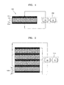
- FIG. 1 is a cross-sectional view of an embodiment of a drinking water filter system.
- first and second activated filters 10a and 10b may be separately disposed to face each other.
- Embodiments of the first and second activated filters 10a and 10b may have various structures such as activated carbon fiber woven fabric (hereinafter referred to as "activated carbon fiber"), activated carbon non-woven fabric, activated carbon paste, a sheet coated with activated carbon slurry and various other similar structures.
- a separation layer 5 may be disposed between the first and second activated filters 10a and 10b.
- the separation layer 5 may be formed of a water permeable insulator.
- embodiments of the separation layer 5 may be formed of a polymer material such as polypropylene, polyester or other materials with similar characteristics.
- a first current collecting layer 20a may be disposed on the outer surface of the first activated carbon filter 10a (the lower surface of the first activated carbon filter 10a as shown in FIG. 1 ) and a second current collecting layer 20b may be disposed on the outer surface of the second activated carbon filter 10b (the upper surface of the second activated carbon filter 10b as shown in FIG. 1 ).
- the first and second current collecting layers 20a and 20b may be formed of a material with low electrical resistance, for example, graphite or other materials with similar characteristics.
- the first and second activated filters 10a and 10b, the separation layer 5, and the first and second current collecting layers 20a and 20b may constitute a filter unit 100.
- Alternative embodiments of the filter unit 100 may not include the separation layer 5 and/or at least one of the first and second current collecting layers 20a and 20b.
- a voltage applying device 200 may be connected to the filter unit 100.
- the first activated carbon filter 10a may be connected to the voltage applying device 200 via the first current collecting layer 20a
- the second activated carbon filter 10b may be connected to the voltage applying device 200 via the second current collecting layer 20b in embodiments where both the first and second current collecting layers 20a and 20b are present, alternatively, the voltage applying device 200 may be directly connected to the first and/or second activated carbon filters 10a and/or 10b.
- the voltage applying device 200 may alternately apply a forward voltage and a reverse voltage between the first and second activated filters 10a and 10b to regenerate the first and second activated filters 10a and 10b.
- the voltage applying device 200 may alternately apply a positive (+) voltage and a negative (-) voltage to the first and second activated filters 10a and 10b in order to alternately apply the forward voltage and the reverse voltage thereto.
- the positive (+) voltage may be a voltage sufficient to induce electrolysis of water between the first and second activated filters 10a and 10b.
- the positive (+) voltage may be a voltage which generates a positive electric potential of at least 1.4 V between the surfaces of first and second activated filters 10a and 10b during the sterilization and regeneration.
- the positive (+) voltage may be greater than about 2 V and equal to or less than about 50 V.
- the first and second activated filters 10a and 10b are used as electrodes during the regeneration process.
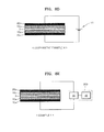
- Embodiments of the voltage applying device 200 may include a power supply 30 connected to the first and second activated filters 10a and 10b and a function generator 40 connected to the power supply 30.
- the power supply 30 may be a device which generates a direct current ("DC") voltage, i.e., a DC power supply.
- the function generator 40 may generate a square wave, a sine wave, a triangle wave, or the like, and the frequency (or pulse width) thereof may be adjusted.
- the forward voltage and the reverse voltage may be alternately applied between the first and second activated filters 10a and 10b using the power supply 30 and the function generator 40. That is, the positive (+) and negative (-) voltages may be alternately applied to the first and second activated filters 10a and 10b.
- alternative embodiments of the voltage applying device 200 may be modified in various forms.
- the filter unit 100 may have a flow through type structure through which water flows. For example, water flows through the water permeable separation layer 5 and the first and second activated filters 10a and 10b, and is discharged out of the drinking water filter system.
- the filter unit 100 may be disposed in a case (not shown) including an inlet and an outlet, and the separation layer 5 may be larger than the first and second activated filters 10a and 10b to be closely disposed on an inner surface of the case.
- holes may be formed in the first activated carbon filter 10a and the first current collecting layer 20a, or holes may be formed in the second activated carbon filter 10b and the second current collecting layer 20b. Water introduced through the inlet in the case may be purified while flowing through the first and second activated filters 10a and 10b after being passed through the separation layer 5 and discharged by the outlet.
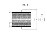
- FIG. 2 Another embodiment of a drinking water filter system as shown in FIG. 2 may include a plurality of the filter units 100 shown in FIG. 1 .
- the first and second activated filters 10a and 10b are referred to as an activated carbon filter 10
- the first and second current collecting layers 20a and 20b are referred to as a current collecting layer 20.
- each of the filter units 100 may include two activated carbon filters 10 and a separation layer 5 between the two activated carbon filters 10.
- Each of the filter units 100 may include current collecting layers 20 disposed on the outside surface of each activated carbon filter 10.
- the current collecting layer 20 disposed between adjacent two filter units 100 may be used as a common current collecting layer for the two filter units 100.
- a plurality of activated carbon filters 10, e.g., in one embodiment an even number of more than four activated carbon filters 10 may be stacked, and the separation layers 5 and the current collecting layers 20 may be alternately stacked between the activated carbon filters 10.
- the current collecting layers 20 may be further disposed on the outer surface of the lowermost activated carbon filter 10 and on the outer surface of the uppermost activated carbon filter 10.
- the positive electrode current collecting layer e.g., an odd numbered current collecting layer 20 as measured from the lowermost layer, e.g., the lowermost layer is an odd numbered layer, the second lowermost layer is an even numbered layer, etc.
- the negative electrode current collecting layer e.g., an even numbered current collecting layer 20 as measured from the lowermost layer, may be commonly connected to a negative electrode terminal of the voltage applying device 200.
- the voltage applying device 200 may be similar to that of FIG. 1 . In other words, the voltage applying device 200 of FIG.
- the negative (+) voltages may be alternately applied to the positive electrode current collecting layer 20 and the negative electrode current collecting layer 20 using the voltage applying device 200.
- the separate filter units 100 are parallelly connected to the voltage applying device 200.
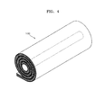
- FIG. 3 shows another embodiment of a drinking water filter system.
- a plurality of activated carbon filters 10, e.g., three or more activated carbon filters 10, may be stacked.
- the separation layer 5 may be disposed between the respective activated carbon filters 10.
- the current collecting layers 20 may be disposed only on the outer surface of the lowermost activated carbon filter 10 and on the outer surface of the uppermost activated carbon filter 10.
- the two current collecting layers 20 may be connected to the voltage applying device 200.
- the voltage applying device 200 may be the same as that of FIG. 1 .
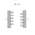
- activated carbon filters 10a, 10b and 10 include a plurality of stacked flat sheet shape. That is, the embodiments of filter units shown in FIGS. 1-3 are plate-type filter units. However, embodiments also include configurations wherein the filter unit may be wound to be in a roll shape as shown in FIG. 4 .
- the filter unit 100' may be in a roll shape.
- the filter unit 100' may have substantially the same structure as the filter unit 100 of FIG. 1 , except that filter unit 100 is wound in a roll shape to result in the filter unit 100'.
- alternative embodiments of the filter unit 100' may be rolled on a wound core.
- the roll-shaped filter unit 100' may be applied to a cylindrical water purifying case (not shown).
- alternative embodiments include configurations wherein the filter unit 100' may have the same structure as the filter units shown in FIGS. 2 and 3 that are then wound into roll shapes.
- alternative embodiments include configurations wherein one of the first and second activated filters 10a and 10b in the drinking water filter system of FIG. 1 may be replaced by a metal layer (not shown). That is, a single activated carbon filter may be used to purify water, and then regenerated.
- the activated carbon filter may be used as a first electrode, and the metal layer may be used as a second electrode during the regeneration of the activated carbon filter.
- a plurality of the filter units using the activated carbon filter as the first electrode and the metal layer as the second electrode may be stacked and may be wound to have a roll shape, e.g., the alternative embodiments including the filter unit including the metal layer may have structures similar to those illustrated in FIGS. 1, 2 and 4 .
- one of the lowermost activated carbon filter 10 and the uppermost activated carbon filter 10 may be replaced by a metal electrode layer.
- FIG. 5A shows first and second activated filters 10a and 10b used for water purification.
- a large number of microorganisms 1 are illustrated as being adsorbed to the first and second activated filters 10a and 10b, thus representing a filter unit in need of regeneration.
- the surface of the microorganisms 1 may have negative charges at neutral pH (potential of hydrogen).
- a positive (+) voltage may be applied to the first activated carbon filter 10a, and a negative (-) voltage may be applied to the second activated carbon filter 10b using the voltage applying device 200 (as illustrated in FIG. 1 ).
- This may be referred to as a forward voltage being applied between the first and second activated filters 10a and 10b.
- Tap water may fill or flow in the filter unit 100 ( FIG. 1 ) while the forward voltage is applied thereto.
- the tap water may be hard water, e.g., the tap water may have a comparative abundance of minerals dissolved therein.
- the adsorbed microorganisms 1 may be oxidized.
- the oxidation of the microorganisms 1 indicates that the microorganisms 1 have been sterilized.
- the oxidized microorganisms 1 are represented by reference numeral 1'.
- the first activated carbon filter 10a to which the positive (+) voltage is applied may directly oxidize the microorganisms 1 by taking electrons from the microorganisms 1 or oxidize the microorganisms 1 using reactive oxygen species (i.e., ozone, hydroxyl radical, etc.), hypochlorous acid (HOCI, OCI - ), etc. generated by electrolysis of water.
- reactive oxygen species i.e., ozone, hydroxyl radical, etc.
- hypochlorous acid HOCI, OCI -
- ions for example, CI - ions are changed to a sterilizing component such as OCI - or HOCI in the vicinity of the first activated carbon filter 10a to which the positive (+) voltage is applied.
- the microorganisms 1 may be sterilized by the sterilizing component of the modified hard water ions.
- hydrogen peroxide (H 2 O 2 ), ozone (O 3 ) and hydroxyl radical (OH radical, ⁇ OH), and the like may be generated on the surface of the first activated carbon filter 10a by the positive (+) voltage.
- oxygen species have stronger oxidizing power than hydrochlorous acid to efficiently sterilize the microorganisms 1.
- the adsorbed microorganisms 1 may be desorbed from the second activated carbon filter 10b by electric repulsion.
- FIG. 5B one microorganism has been illustrated as surviving the sterilization process as the application of the voltage may not be 100% effective; however, repeated application of the voltage may result in complete sterilization as discussed in more detail below
- the applied voltages may be alternated and a negative (-) voltage may be applied to the first activated carbon filter 10a, and a positive (+) voltage may be applied to the second activated carbon filter 10b.
- This may be referred to as a reverse voltage application between the first and second activated filters 10a and 10b. While the reverse voltage is applied thereto, the microorganisms 1 are adsorbed to the second activated carbon filter 10b to which the positive (+) voltage is applied and oxidized (sterilized). The microorganisms 1 and 1' may be desorbed from the first activated carbon filter 10a to which the negative (-) voltage is applied.
- the positive (+) voltage may be a voltage capable of inducing electrolysis of water between the first and second activated filters 10a and 10b.
- the positive (+) voltage may be a voltage generating a positive electric potential of at least 1.4 V on the surfaces of first and second activated filters 10a and 10b.
- the positive (+) voltage may be greater than about 2 V and equal to or less than about 50 V.
- the sterilization of the microorganisms 1 may be efficiently performed using the voltage within the range described above. Water may be electrolyzed when the surface electric potential is about 1.2 V or greater.
- hydrochlorous acid (HOCI, OCI - ) may be generated when the surface electric potential of the first and second activated filters 10a and 10b is about 1.4 V or greater
- hydrogen peroxide H 2 O0 2
- ozone O 3
- the hydroxyl radical may be generated when the surface electric potential of the first and second activated filters 10a and 10b is about 2.7 V or greater.
- the oxidizing/sterilizing components may be efficiently generated and desired chemical reaction (sterilization) may be performed by using a positive (+) voltage that generates an electric potential of 1.2 V or greater on the surface of the first and second activated filters 10a and 10b. Due to the resistance of the first and second activated filters 10a and 10b, a positive (+) voltage of 2 V or greater may applied to the activated filters 10a and 10b in order to generate an electric potential of 1.4 V or greater on the surface of the first and second activated filters 10a and 10b.
- the initial intensity of the positive (+) voltage to induce the sterilization/oxidization may vary according to the configuration of the filter system.
- the negative (-) voltage induces the desorption of microorganisms 1 and 1', respectively.
- FIGS. 5B and 5C may be alternately repeated. That is, "sterilization ⁇ desorption ⁇ sterilization ⁇ desorption" are repeated by alternately applying the positive (+) voltage and the negative (-) voltage to the first and second activated filters 10a and 10b using the first and second activated filters 10a and 10b as electrodes, e.g., by alternately applying the forward voltage and the reverse voltage to the first and second activated filters 10a and 10b, to efficiently regenerate the first and second activated filters 10a and 10b.
- tap water flows into the filter unit 100 ( FIG.
- embodiments include configurations wherein tap water flowed into the filter unit 100 passes through the filter unit 100 and is discharged out of the filter unit 100.
- alternative embodiments include configurations wherein tap water may be circulated in the filter unit 100 during the regeneration process.
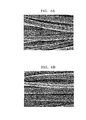
- FIGS. 6A and 6B are scanning electron microscopic ("SEM") images of microorganisms adsorbed on activated carbon filters to which a positive (+) voltage and a negative (-) voltage are respectively applied for 5 minutes, respectively.
- SEM scanning electron microscopic
- a large number of microorganisms (illustrated as white flaky material on the activated carbon fibers) are adsorbed on the activated carbon filter to which a positive (+) voltage is applied. Most of the microorganisms adsorbed to the activated carbon filter may be sterilized by oxidation.
- the first and second activated filters 10a and 10b are used as electrodes, and thus additional metal electrodes are not necessary.
- tap water may be used instead of high concentration electrolyte.
- the structure of the regenerative filter system may be simplified, and the filter system may be simply and quickly regenerated.
- Regeneration efficiencies of an embodiment of a drinking water filter system for various pollution conditions are shown in Table 1 below.
- Table 1 Pollution degree of influent (CFU/ml) Pollution degree of effluent before regeneration (CFU/ml) Pollution degree of effluent after regeneration (CFU/ml) Regeneration efficiency (%) 1 2 ⁇ 10 5 30 5 84 2 2 ⁇ 10 6 100 10 90 3 5 ⁇ 10 6 245 50 80 4 1 ⁇ 10 7 1367 87 94 5 2 ⁇ 10 7 5030 303 94
- Table 1 shows the results obtained using the embodiment of a drinking water filter system shown in FIG. 1 .
- an activated carbon fiber having a size of 10 ⁇ 10 cm 2 was used for the first and second activated filters 10a and 10b, a graphite foil was used as the current collecting layer 20 and a separation layer 5 had a mesh structure.
- 200 ml of simulated tap water ( ⁇ 0 CFU/ml, 500 ⁇ S/cm, CI - 60 ppm) was circulated in the polluted filter unit at a flow rate of 50 ml/min during regeneration of the filter unit according to the embodiment of a method described above.
- a positive (+) voltage of about +3V and a negative (-) voltage of about -3 V were alternately applied to two activated carbon filters for 5 minutes each, for 20 minutes in total.
- 200 ml of simulated tap water ( ⁇ 0 CFU/ml, 500 ⁇ S/cm, CI - 60 ppm) was passed through the regenerated filter unit at a flow rate of 50 ml/min.
- the pollution degree of the effluent was measured and shown as 'pollution degree of effluent after regeneration' in Table 1. Meanwhile, 'regeneration efficiency' of Table 1 was obtained by multiplying (1 - pollution degree after regeneration/pollution degree before regeneration) by 100.
- the concentration of the microorganisms contained in the effluent after regeneration was reduced by about 80% to 94% compared with that of the microorganisms contained in the effluent before regeneration. If the pollution degree was 2 ⁇ 10 7 CFU/ml, the pollution degree before regeneration was about 5030 CFU/ml, while the pollution degree after regeneration was about 303 CFU/ml. In addition, in such a degree of pollution, the regeneration efficiency is about 94%.
- the results of Table 1 are shown in a graph of FIG. 7 (please note that FIG. 7 is illustrated with an logarithmic scale).
- FIGS. 8A to 8E Drinking water filter systems according to Comparative Examples 1 to 4 and Embodiment 1 shown in Table 2 are illustrated in FIGS. 8A to 8E .
- the drinking water filter system of Comparative Example 1 separation layers 5 are disposed between the first activated carbon filter 10a and the first current collecting layer 20a, between the first and second activated carbon filters 10a and 10b, and between the second activated carbon filter 10b and the second current collecting layer 20b.
- the first and second current collecting layers 20a and 20b are connected to a DC power supply V1.
- the first and second activated carbon filters 10a and 10b are not electrically connected to the DC power supply V1, they are not used as electrodes, e.g., their function as electrodes is prevented by the insertion of the separation layer 5 between them and the current collection layers 20a and 20b. Instead, the first and second current collecting layers 20a and 20b are used as electrodes.
- the DC power supply V1 is also used in FIGS. 8B and 8D .
- a single activated carbon filter 10 is used as the positive (+) electrode.
- the separation layer 5 and the first current collecting layer 20a are sequentially disposed on the lower surface of the activated carbon filter 10, and the second current collecting layer 20b is disposed on the upper surface of the activated carbon filter 10.
- the first and second current collecting layers 20a and 20b are respectively connected to the negative (-) and a positive (+) terminals of the DC power supply V1.
- the activated carbon filter 10 is used as the positive (+) electrode
- the first current collecting layer 20a is used as the negative (-) electrode.
- a positive (+) voltage and a negative (-) voltage cannot be alternately applied to the activated carbon filter 10. That is, a reverse voltage is not applied to the activated carbon filter 10.
- the separation layer 5 prevents the carbon filter 10 from being used as a negative (-) electrode.
- a single activated carbon filter 10 is used as a negative (-) electrode.
- This embodiment is similar to that illustrated in FIG. 8B if the terminals to the DC power supply V1 were reversed. That is, the first current collecting layer 20a is disposed on the lower surface of the activated carbon filter 10, and the separation layer 5 and the second current collecting layer 20b are sequentially disposed on the upper surface of the activated carbon filter 10.
- the first and second current collecting layers 20a and 20b are respectively connected to the negative (-) and positive (+) terminals of the DC power supply V1.
- the activated carbon filter 10 is used as the negative (-) electrode, and the second current collecting layer 20b is used as the positive (+) electrode.
- a positive (+) voltage and a negative (-) voltage may not be alternately applied to the activated carbon filter 10. That is, a reverse voltage is not applied to the activated carbon filter 10.
- the drinking water filter system of Comparative Example 4 the first and second activated filters 10a and 10b are separately disposed on both sides of the separation layer 5, the first current collecting layer 20a is disposed on the lower surface of the first activated carbon filter 10a, and the second current collecting layer 20b is disposed on the upper surface of the second activated carbon filter 10b.
- the first and second current collecting layers 20a and 20b are respectively connected to the negative (-) and positive (+) terminals of the DC power supply V1.
- both of the first and second activated carbon filters 10a and 10b are used as electrodes, a positive (+) voltage and a negative (-) voltage may not be alternately applied to the first and second activated carbon filters 10a and 10b during the regeneration because the DC power supply V1 applies only a direct current to the first activated carbon filter 10a and the second activated carbon filter 10b. That is, a reverse voltage is not applied to the first and second activated carbon filters 10a and 10b.
- the drinking water filter system according to Embodiment 1 has the same structure shown in the embodiment of FIG. 1 .
- both of the first and second activated carbon filters 10a and 10b are used as electrodes, a positive (+) voltage and a negative (-) voltage are alternately applied to the first and second activated carbon filters 10a and 10b during the regeneration process. That is, a forward voltage and a reverse voltage are alternately applied to the first and second activated carbon filters 10a and 10b.
- Activated carbon fiber is used for the activated carbon filters 10a, 10b, and 10 shown in FIGS. 8A to 8E .
- the drinking water filter systems according to Comparative Examples 1 and 2 have very low regeneration efficiencies of 0% and 9%, respectively. Even though the drinking water filter systems according to Comparative Examples 3 and 4 have regeneration efficiencies of 59% and 70%, respectively, the regeneration efficiency is far less than the regeneration efficiency (94%) of the drinking water filter system according to Embodiment 1.
- the embodiment of a drinking water filter system illustrated in FIG. 1 (and FIG. 8E ) may have excellent regeneration efficiency by using both of the first and second activated carbon filters 10a and 10b as electrodes, and alternately applying a positive voltage and a negative voltage to the first and second activated carbon filters 10a and 10b, when compared to the drinking water filter systems according to Comparative Examples 1 to 4.
- the pollution degree (CFU/ml) before and after the regeneration of the drinking water filter system according to another embodiment and regeneration efficiency (%) thereof are shown in Table 3 below.
- an activated carbon fiber was used for the activated carbon filter in Embodiment 1 as shown in Table 2
- activated carbon paste was used for the activated carbon filters in Embodiments 2 to 4 as shown in Table 3.
- PC manufactured by Osaka Gas Co., Ltd. was used as a powdered active material used to prepare the paste in Embodiments 2 and 3
- MSP manufactured by Kansai Coke and Chemicals Co., Ltd. was used as a powdered active material used to prepare the paste in Embodiment 4.
- Embodiments 2 to 4 shown in Table 3 below was substantially the same as that in Embodiment 1, except that the material used to prepare the activated carbon filter varied.
- All other conditions for pollution and treating water i.e., simulated tap water
- Embodiments 2, 3 and 4 were about 90%, 90% and 86%, respectively.
- a regenerative drinking water filter system having a simple configuration may be manufactured.
- the drinking water filter system may be electrochemically sterilized and regenerated using an in-situ method without adding additives such as an electrolyte. Therefore, the drinking water filter system may be hygienically managed, thereby maintaining stability of the hygiene of drinking water. In addition, the lifetime of the drinking water filter system may increase.
- the drinking water filter system may be applied a variety of water purifying devices.
- the drinking water filter system may be applied to a water purifying device for home use, a water dispenser of a refrigerator, a kettle-shaped water purifying device, a direct faucet connected water purifying device, etc.
- the embodiments disclosed herein may also be applied to a water purifying device for industrial use in addition to the water purifying device for home use.
- the configuration of the water purifying device employing the drinking water filter system is well-known, and thus description thereof will be omitted herein.
- the embodiments described therein should be considered in a descriptive sense only and not for purposes of limitation. Descriptions of features or aspects within each embodiment should typically be considered as available for other similar features or aspects in other embodiments.
- the components and configuration of the drinking water filter systems of FIGS. 1 to 4 may be modified in various ways.
- the activated carbon filters 10, 10a, and 10b shown in the drinking water filter systems of FIGS. 1 to 4 may also be any filters formed of a material that is not activated carbon.
- the method of regenerating the drinking water filter system described with reference to FIGS. 5A to 5C may vary.
Landscapes
- Chemical & Material Sciences (AREA)
- Life Sciences & Earth Sciences (AREA)
- Hydrology & Water Resources (AREA)
- Engineering & Computer Science (AREA)
- Environmental & Geological Engineering (AREA)
- Water Supply & Treatment (AREA)
- Organic Chemistry (AREA)
- Chemical Kinetics & Catalysis (AREA)
- Electrochemistry (AREA)
- General Chemical & Material Sciences (AREA)
- Water Treatment By Electricity Or Magnetism (AREA)
- Water Treatment By Sorption (AREA)
Applications Claiming Priority (1)
| Application Number | Priority Date | Filing Date | Title |
|---|---|---|---|
| KR1020090077608A KR20110019968A (ko) | 2009-08-21 | 2009-08-21 | 정수 필터 시스템과 그의 재생방법 및 정수 필터 시스템을 포함하는 정수 장치 |
Publications (3)
| Publication Number | Publication Date |
|---|---|
| EP2298441A2 true EP2298441A2 (de) | 2011-03-23 |
| EP2298441A3 EP2298441A3 (de) | 2012-05-30 |
| EP2298441B1 EP2298441B1 (de) | 2016-05-18 |
Family
ID=43066670
Family Applications (1)
| Application Number | Title | Priority Date | Filing Date |
|---|---|---|---|
| EP10172934.1A Not-in-force EP2298441B1 (de) | 2009-08-21 | 2010-08-16 | Trinkwasserfiltersystem, Verfahren zu seiner Regeneration und Wasserreinigungsvorrichtung mit dem Trinkwasserfiltersystem |
Country Status (3)
| Country | Link |
|---|---|
| US (1) | US20110042236A1 (de) |
| EP (1) | EP2298441B1 (de) |
| KR (1) | KR20110019968A (de) |
Cited By (4)
| Publication number | Priority date | Publication date | Assignee | Title |
|---|---|---|---|---|
| EP2478956A1 (de) * | 2011-01-21 | 2012-07-25 | Samsung Electronics Co., Ltd. | Regenerierbare Absorptionsvorrichtung und Verfahren zu deren Steuerung |
| CN102897874A (zh) * | 2011-07-29 | 2013-01-30 | 通用电气公司 | 制备杀菌剂的方法 |
| EP2714236A4 (de) * | 2011-05-26 | 2015-07-08 | Biolargo Life Technologies Inc | Aktivkohle mit jodid |
| EP3002254A1 (de) * | 2014-09-25 | 2016-04-06 | Judo Wasseraufbereitung GmbH | Wasserfilter-anordnung umfassend einen rückspülbaren wasserfilter mit elektrolytischer reinigungsfunktion |
Families Citing this family (9)
| Publication number | Priority date | Publication date | Assignee | Title |
|---|---|---|---|---|
| US10238990B2 (en) * | 2008-01-18 | 2019-03-26 | Kenneth R. Code | Apparatus for removing contamination via electrodes and a two-layered filter comprising carbon and an activating agent |
| US9839868B2 (en) | 2010-06-15 | 2017-12-12 | Karl J. Fritze | Electrically enhanced filter cartridge and methods for its use |
| WO2013012623A1 (en) | 2011-07-18 | 2013-01-24 | Carrier Corporation | Control of atmosphere within a closed environment |
| US9375663B2 (en) | 2014-05-30 | 2016-06-28 | Ozono Polaris, S.A. de C.V. | Sanitization and regeneration of porous filter media with ozone in backwash |
| CN105692778B (zh) * | 2016-03-07 | 2019-03-22 | 圆融健康科技(深圳)有限公司 | 深紫外水体智能杀菌装置和深紫外智能杀菌系统 |
| CN105948161A (zh) * | 2016-06-13 | 2016-09-21 | 西安交通大学 | 一种去除硫酸铵溶液中有机物的装置和方法及该装置的制作方法 |
| WO2019123428A1 (en) | 2017-12-22 | 2019-06-27 | Ozono Polaris, S.A. de C.V. | Process and system for back-and-forth washing of adsorptive media |
| US20220127169A1 (en) * | 2019-02-28 | 2022-04-28 | University Of Georgia Research Foundation, Inc. | Reactive electrochemical membrane system and methods of making and using |
| US20250230065A1 (en) * | 2024-01-17 | 2025-07-17 | King Abdulaziz University | Steam-activated carbon nanoparticles of oil fly ash and date palm fronds for contaminant removal from water |
Family Cites Families (15)
| Publication number | Priority date | Publication date | Assignee | Title |
|---|---|---|---|---|
| CH545130A (fr) * | 1970-09-15 | 1973-12-15 | Battelle Memorial Institute | Procédé de purification d'une solution conductrice ionique |
| JPS5799389A (en) * | 1980-12-15 | 1982-06-21 | Toshiba Corp | Metal ion collector |
| US5425858A (en) * | 1994-05-20 | 1995-06-20 | The Regents Of The University Of California | Method and apparatus for capacitive deionization, electrochemical purification, and regeneration of electrodes |
| ID18692A (id) * | 1996-11-05 | 1998-04-30 | Sanden Corp | Instalasi pembersih air dengan fungsi penghasil klorin bersama dengan fungsi ilmu gangguan bakteri |
| US5770037A (en) * | 1996-11-21 | 1998-06-23 | Konica Corporation | Water processing method |
| US5904832A (en) * | 1996-12-20 | 1999-05-18 | Huron Tech Canada, Inc. | Regeneration of active carbon and polymeric adsorbents |
| RU2110482C1 (ru) * | 1997-03-19 | 1998-05-10 | Вестерн Пасифик Компани Инк. | Способ электрохимически управляемой сорбции растворимых органических веществ и ионов тяжелых металлов из водных растворов и устройство для его реализации |
| CN1081167C (zh) * | 1997-06-05 | 2002-03-20 | 大连理工大学 | 连续吸附-电解再生污水处理设备 |
| US6778378B1 (en) * | 1999-07-30 | 2004-08-17 | Biosource, Inc. | Flow-through capacitor and method |
| RU2171139C1 (ru) * | 2000-01-05 | 2001-07-27 | Общество с ограниченной ответственностью "Аквафор" | Композиционный регенерируемый адсорбционный углеродный материал и способ его регенерации |
| JP2003164880A (ja) * | 2001-11-30 | 2003-06-10 | Sanyo Electric Co Ltd | 水処理方法、水処理装置及びそれを用いた水耕栽培システム |
| JP2005034705A (ja) * | 2003-07-16 | 2005-02-10 | Mitsubishi Heavy Ind Ltd | 吸着材の再生方法及び再生装置 |
| US7267710B2 (en) * | 2003-03-28 | 2007-09-11 | Mitsubishi Heavy Industries, Ltd. | Method of and apparatus for regenerating adsorbent |
| US8097130B2 (en) * | 2006-10-18 | 2012-01-17 | Balboa Instruments, Inc. | Integrated water treatment system |
| WO2009053972A1 (en) * | 2007-10-22 | 2009-04-30 | Toxsorb Ltd | Modified activated carbon as adsorbent for anionic and cationic inorganic pollutants |
-
2009
- 2009-08-21 KR KR1020090077608A patent/KR20110019968A/ko not_active Ceased
-
2010
- 2010-02-24 US US12/711,374 patent/US20110042236A1/en not_active Abandoned
- 2010-08-16 EP EP10172934.1A patent/EP2298441B1/de not_active Not-in-force
Non-Patent Citations (1)
| Title |
|---|
| None |
Cited By (5)
| Publication number | Priority date | Publication date | Assignee | Title |
|---|---|---|---|---|
| EP2478956A1 (de) * | 2011-01-21 | 2012-07-25 | Samsung Electronics Co., Ltd. | Regenerierbare Absorptionsvorrichtung und Verfahren zu deren Steuerung |
| EP2714236A4 (de) * | 2011-05-26 | 2015-07-08 | Biolargo Life Technologies Inc | Aktivkohle mit jodid |
| CN102897874A (zh) * | 2011-07-29 | 2013-01-30 | 通用电气公司 | 制备杀菌剂的方法 |
| WO2013019427A1 (en) * | 2011-07-29 | 2013-02-07 | General Electric Company | Method for generating biocide |
| EP3002254A1 (de) * | 2014-09-25 | 2016-04-06 | Judo Wasseraufbereitung GmbH | Wasserfilter-anordnung umfassend einen rückspülbaren wasserfilter mit elektrolytischer reinigungsfunktion |
Also Published As
| Publication number | Publication date |
|---|---|
| EP2298441B1 (de) | 2016-05-18 |
| US20110042236A1 (en) | 2011-02-24 |
| KR20110019968A (ko) | 2011-03-02 |
| EP2298441A3 (de) | 2012-05-30 |
Similar Documents
| Publication | Publication Date | Title |
|---|---|---|
| EP2298441B1 (de) | Trinkwasserfiltersystem, Verfahren zu seiner Regeneration und Wasserreinigungsvorrichtung mit dem Trinkwasserfiltersystem | |
| JP6214063B2 (ja) | 廃水処理のための電解セルでの濾過能力の付与方法 | |
| TWI381996B (zh) | 混合式電極之電容去離子裝置 | |
| CN110002530B (zh) | 膜吸附组件、可再生膜吸附反应器、液体处理装置及方法 | |
| TWI327558B (en) | A total solution for water treatments | |
| JP5764474B2 (ja) | 電解合成装置、電解処理装置、電解合成方法及び電解処理方法 | |
| US20100270161A1 (en) | Apparatus for physically separating polar substance | |
| CN110809564B (zh) | 脱盐设备及其制造方法 | |
| KR101842552B1 (ko) | 전해-탄소여과필터 및 이를 이용한 수처리장치 | |
| JP2009190016A (ja) | 水浄化処理用電解キャパシター内のバイオフィルム除去及び防止方法 | |
| KR102211119B1 (ko) | Cdi 방식의 수처리 장치 | |
| KR20150061323A (ko) | 전기 흡착 탈이온 전극 재생 방법 | |
| Wang et al. | Square-wave alternating voltage for enhancing Cr (VI) reduction in a carbon fiber-based flow-through electrode system | |
| CN101891331A (zh) | 活性炭吸附与电化学再生一体化处理装置及其使用方法 | |
| KR101394112B1 (ko) | 전기 흡착식 수처리 셀, 이를 이용한 전기 흡착식 수처리 장치 및 방법. | |
| CN110730763A (zh) | 用于水溶性有机废物处理的设备和方法 | |
| EP2508482A1 (de) | Vorrichtung und Verfahren zur elektrolytischen Erzeugung von reduzierendem Wasser | |
| CN103435132B (zh) | 一种活性炭纤维处理含油废水及其再生方法和装置 | |
| CN101624229A (zh) | 混合式电极的电容去离子装置 | |
| KR101939365B1 (ko) | 필터 장치 및 상기 필터 장치의 작동 방법 | |
| CN102060358A (zh) | 利用活性炭纤维电极高压脉冲电解降解水中藻毒素的方法及其单元装置 | |
| JP2003200166A (ja) | 通液型電気二重層コンデンサ脱塩装置の運転方法 | |
| WO2008038853A1 (en) | Activated carbon - granule electrode filter | |
| JP3729347B2 (ja) | 電気再生式脱塩装置 | |
| CN217051729U (zh) | 一种水体去离子过滤器 |
Legal Events
| Date | Code | Title | Description |
|---|---|---|---|
| PUAI | Public reference made under article 153(3) epc to a published international application that has entered the european phase |
Free format text: ORIGINAL CODE: 0009012 |
|
| AK | Designated contracting states |
Kind code of ref document: A2 Designated state(s): AL AT BE BG CH CY CZ DE DK EE ES FI FR GB GR HR HU IE IS IT LI LT LU LV MC MK MT NL NO PL PT RO SE SI SK SM TR |
|
| AX | Request for extension of the european patent |
Extension state: BA ME RS |
|
| PUAL | Search report despatched |
Free format text: ORIGINAL CODE: 0009013 |
|
| RIC1 | Information provided on ipc code assigned before grant |
Ipc: C02F 1/28 20060101ALI20120420BHEP Ipc: B01J 20/16 20060101ALI20120420BHEP Ipc: C02F 101/22 20060101ALN20120420BHEP Ipc: C02F 1/461 20060101ALI20120420BHEP Ipc: C02F 103/02 20060101ALN20120420BHEP Ipc: B01J 20/12 20060101ALI20120420BHEP Ipc: B01J 20/34 20060101AFI20120420BHEP Ipc: C02F 101/20 20060101ALN20120420BHEP Ipc: B01D 15/00 20060101ALI20120420BHEP Ipc: B01J 20/20 20060101ALI20120420BHEP |
|
| AK | Designated contracting states |
Kind code of ref document: A3 Designated state(s): AL AT BE BG CH CY CZ DE DK EE ES FI FR GB GR HR HU IE IS IT LI LT LU LV MC MK MT NL NO PL PT RO SE SI SK SM TR |
|
| AX | Request for extension of the european patent |
Extension state: BA ME RS |
|
| RAP1 | Party data changed (applicant data changed or rights of an application transferred) |
Owner name: SAMSUNG ELECTRONICS CO., LTD. |
|
| 17P | Request for examination filed |
Effective date: 20121130 |
|
| 17Q | First examination report despatched |
Effective date: 20130306 |
|
| GRAP | Despatch of communication of intention to grant a patent |
Free format text: ORIGINAL CODE: EPIDOSNIGR1 |
|
| INTG | Intention to grant announced |
Effective date: 20151125 |
|
| GRAS | Grant fee paid |
Free format text: ORIGINAL CODE: EPIDOSNIGR3 |
|
| GRAA | (expected) grant |
Free format text: ORIGINAL CODE: 0009210 |
|
| AK | Designated contracting states |
Kind code of ref document: B1 Designated state(s): AL AT BE BG CH CY CZ DE DK EE ES FI FR GB GR HR HU IE IS IT LI LT LU LV MC MK MT NL NO PL PT RO SE SI SK SM TR |
|
| REG | Reference to a national code |
Ref country code: GB Ref legal event code: FG4D |
|
| REG | Reference to a national code |
Ref country code: CH Ref legal event code: EP |
|
| REG | Reference to a national code |
Ref country code: IE Ref legal event code: FG4D Ref country code: AT Ref legal event code: REF Ref document number: 799942 Country of ref document: AT Kind code of ref document: T Effective date: 20160615 |
|
| REG | Reference to a national code |
Ref country code: DE Ref legal event code: R096 Ref document number: 602010033426 Country of ref document: DE |
|
| REG | Reference to a national code |
Ref country code: FR Ref legal event code: PLFP Year of fee payment: 7 |
|
| REG | Reference to a national code |
Ref country code: NL Ref legal event code: MP Effective date: 20160518 |
|
| REG | Reference to a national code |
Ref country code: LT Ref legal event code: MG4D |
|
| PG25 | Lapsed in a contracting state [announced via postgrant information from national office to epo] |
Ref country code: LT Free format text: LAPSE BECAUSE OF FAILURE TO SUBMIT A TRANSLATION OF THE DESCRIPTION OR TO PAY THE FEE WITHIN THE PRESCRIBED TIME-LIMIT Effective date: 20160518 Ref country code: NL Free format text: LAPSE BECAUSE OF FAILURE TO SUBMIT A TRANSLATION OF THE DESCRIPTION OR TO PAY THE FEE WITHIN THE PRESCRIBED TIME-LIMIT Effective date: 20160518 Ref country code: NO Free format text: LAPSE BECAUSE OF FAILURE TO SUBMIT A TRANSLATION OF THE DESCRIPTION OR TO PAY THE FEE WITHIN THE PRESCRIBED TIME-LIMIT Effective date: 20160818 Ref country code: FI Free format text: LAPSE BECAUSE OF FAILURE TO SUBMIT A TRANSLATION OF THE DESCRIPTION OR TO PAY THE FEE WITHIN THE PRESCRIBED TIME-LIMIT Effective date: 20160518 |
|
| PGFP | Annual fee paid to national office [announced via postgrant information from national office to epo] |
Ref country code: GB Payment date: 20160804 Year of fee payment: 7 Ref country code: DE Payment date: 20160719 Year of fee payment: 7 |
|
| REG | Reference to a national code |
Ref country code: AT Ref legal event code: MK05 Ref document number: 799942 Country of ref document: AT Kind code of ref document: T Effective date: 20160518 |
|
| PG25 | Lapsed in a contracting state [announced via postgrant information from national office to epo] |
Ref country code: SE Free format text: LAPSE BECAUSE OF FAILURE TO SUBMIT A TRANSLATION OF THE DESCRIPTION OR TO PAY THE FEE WITHIN THE PRESCRIBED TIME-LIMIT Effective date: 20160518 Ref country code: ES Free format text: LAPSE BECAUSE OF FAILURE TO SUBMIT A TRANSLATION OF THE DESCRIPTION OR TO PAY THE FEE WITHIN THE PRESCRIBED TIME-LIMIT Effective date: 20160518 Ref country code: GR Free format text: LAPSE BECAUSE OF FAILURE TO SUBMIT A TRANSLATION OF THE DESCRIPTION OR TO PAY THE FEE WITHIN THE PRESCRIBED TIME-LIMIT Effective date: 20160819 Ref country code: PT Free format text: LAPSE BECAUSE OF FAILURE TO SUBMIT A TRANSLATION OF THE DESCRIPTION OR TO PAY THE FEE WITHIN THE PRESCRIBED TIME-LIMIT Effective date: 20160919 Ref country code: HR Free format text: LAPSE BECAUSE OF FAILURE TO SUBMIT A TRANSLATION OF THE DESCRIPTION OR TO PAY THE FEE WITHIN THE PRESCRIBED TIME-LIMIT Effective date: 20160518 Ref country code: LV Free format text: LAPSE BECAUSE OF FAILURE TO SUBMIT A TRANSLATION OF THE DESCRIPTION OR TO PAY THE FEE WITHIN THE PRESCRIBED TIME-LIMIT Effective date: 20160518 |
|
| PGFP | Annual fee paid to national office [announced via postgrant information from national office to epo] |
Ref country code: FR Payment date: 20160830 Year of fee payment: 7 |
|
| PG25 | Lapsed in a contracting state [announced via postgrant information from national office to epo] |
Ref country code: IT Free format text: LAPSE BECAUSE OF FAILURE TO SUBMIT A TRANSLATION OF THE DESCRIPTION OR TO PAY THE FEE WITHIN THE PRESCRIBED TIME-LIMIT Effective date: 20160518 Ref country code: BE Free format text: LAPSE BECAUSE OF NON-PAYMENT OF DUE FEES Effective date: 20160831 |
|
| PG25 | Lapsed in a contracting state [announced via postgrant information from national office to epo] |
Ref country code: CZ Free format text: LAPSE BECAUSE OF FAILURE TO SUBMIT A TRANSLATION OF THE DESCRIPTION OR TO PAY THE FEE WITHIN THE PRESCRIBED TIME-LIMIT Effective date: 20160518 Ref country code: EE Free format text: LAPSE BECAUSE OF FAILURE TO SUBMIT A TRANSLATION OF THE DESCRIPTION OR TO PAY THE FEE WITHIN THE PRESCRIBED TIME-LIMIT Effective date: 20160518 Ref country code: DK Free format text: LAPSE BECAUSE OF FAILURE TO SUBMIT A TRANSLATION OF THE DESCRIPTION OR TO PAY THE FEE WITHIN THE PRESCRIBED TIME-LIMIT Effective date: 20160518 Ref country code: SK Free format text: LAPSE BECAUSE OF FAILURE TO SUBMIT A TRANSLATION OF THE DESCRIPTION OR TO PAY THE FEE WITHIN THE PRESCRIBED TIME-LIMIT Effective date: 20160518 Ref country code: RO Free format text: LAPSE BECAUSE OF FAILURE TO SUBMIT A TRANSLATION OF THE DESCRIPTION OR TO PAY THE FEE WITHIN THE PRESCRIBED TIME-LIMIT Effective date: 20160518 |
|
| REG | Reference to a national code |
Ref country code: DE Ref legal event code: R097 Ref document number: 602010033426 Country of ref document: DE |
|
| PG25 | Lapsed in a contracting state [announced via postgrant information from national office to epo] |
Ref country code: AT Free format text: LAPSE BECAUSE OF FAILURE TO SUBMIT A TRANSLATION OF THE DESCRIPTION OR TO PAY THE FEE WITHIN THE PRESCRIBED TIME-LIMIT Effective date: 20160518 Ref country code: PL Free format text: LAPSE BECAUSE OF FAILURE TO SUBMIT A TRANSLATION OF THE DESCRIPTION OR TO PAY THE FEE WITHIN THE PRESCRIBED TIME-LIMIT Effective date: 20160518 Ref country code: SM Free format text: LAPSE BECAUSE OF FAILURE TO SUBMIT A TRANSLATION OF THE DESCRIPTION OR TO PAY THE FEE WITHIN THE PRESCRIBED TIME-LIMIT Effective date: 20160518 Ref country code: BE Free format text: LAPSE BECAUSE OF FAILURE TO SUBMIT A TRANSLATION OF THE DESCRIPTION OR TO PAY THE FEE WITHIN THE PRESCRIBED TIME-LIMIT Effective date: 20160518 |
|
| PLBE | No opposition filed within time limit |
Free format text: ORIGINAL CODE: 0009261 |
|
| STAA | Information on the status of an ep patent application or granted ep patent |
Free format text: STATUS: NO OPPOSITION FILED WITHIN TIME LIMIT |
|
| PG25 | Lapsed in a contracting state [announced via postgrant information from national office to epo] |
Ref country code: MC Free format text: LAPSE BECAUSE OF FAILURE TO SUBMIT A TRANSLATION OF THE DESCRIPTION OR TO PAY THE FEE WITHIN THE PRESCRIBED TIME-LIMIT Effective date: 20160518 |
|
| REG | Reference to a national code |
Ref country code: CH Ref legal event code: PL |
|
| 26N | No opposition filed |
Effective date: 20170221 |
|
| PG25 | Lapsed in a contracting state [announced via postgrant information from national office to epo] |
Ref country code: CH Free format text: LAPSE BECAUSE OF NON-PAYMENT OF DUE FEES Effective date: 20160831 Ref country code: LI Free format text: LAPSE BECAUSE OF NON-PAYMENT OF DUE FEES Effective date: 20160831 |
|
| PG25 | Lapsed in a contracting state [announced via postgrant information from national office to epo] |
Ref country code: SI Free format text: LAPSE BECAUSE OF FAILURE TO SUBMIT A TRANSLATION OF THE DESCRIPTION OR TO PAY THE FEE WITHIN THE PRESCRIBED TIME-LIMIT Effective date: 20160518 |
|
| REG | Reference to a national code |
Ref country code: IE Ref legal event code: MM4A |
|
| PG25 | Lapsed in a contracting state [announced via postgrant information from national office to epo] |
Ref country code: IE Free format text: LAPSE BECAUSE OF NON-PAYMENT OF DUE FEES Effective date: 20160816 |
|
| PG25 | Lapsed in a contracting state [announced via postgrant information from national office to epo] |
Ref country code: LU Free format text: LAPSE BECAUSE OF NON-PAYMENT OF DUE FEES Effective date: 20160816 |
|
| REG | Reference to a national code |
Ref country code: DE Ref legal event code: R119 Ref document number: 602010033426 Country of ref document: DE |
|
| GBPC | Gb: european patent ceased through non-payment of renewal fee |
Effective date: 20170816 |
|
| REG | Reference to a national code |
Ref country code: FR Ref legal event code: ST Effective date: 20180430 |
|
| PG25 | Lapsed in a contracting state [announced via postgrant information from national office to epo] |
Ref country code: CY Free format text: LAPSE BECAUSE OF FAILURE TO SUBMIT A TRANSLATION OF THE DESCRIPTION OR TO PAY THE FEE WITHIN THE PRESCRIBED TIME-LIMIT Effective date: 20160518 Ref country code: HU Free format text: LAPSE BECAUSE OF FAILURE TO SUBMIT A TRANSLATION OF THE DESCRIPTION OR TO PAY THE FEE WITHIN THE PRESCRIBED TIME-LIMIT; INVALID AB INITIO Effective date: 20100816 |
|
| PG25 | Lapsed in a contracting state [announced via postgrant information from national office to epo] |
Ref country code: TR Free format text: LAPSE BECAUSE OF FAILURE TO SUBMIT A TRANSLATION OF THE DESCRIPTION OR TO PAY THE FEE WITHIN THE PRESCRIBED TIME-LIMIT Effective date: 20160518 Ref country code: MT Free format text: LAPSE BECAUSE OF NON-PAYMENT OF DUE FEES Effective date: 20160831 Ref country code: MK Free format text: LAPSE BECAUSE OF FAILURE TO SUBMIT A TRANSLATION OF THE DESCRIPTION OR TO PAY THE FEE WITHIN THE PRESCRIBED TIME-LIMIT Effective date: 20160518 Ref country code: IS Free format text: LAPSE BECAUSE OF FAILURE TO SUBMIT A TRANSLATION OF THE DESCRIPTION OR TO PAY THE FEE WITHIN THE PRESCRIBED TIME-LIMIT Effective date: 20160518 |
|
| PG25 | Lapsed in a contracting state [announced via postgrant information from national office to epo] |
Ref country code: DE Free format text: LAPSE BECAUSE OF NON-PAYMENT OF DUE FEES Effective date: 20180301 Ref country code: BG Free format text: LAPSE BECAUSE OF FAILURE TO SUBMIT A TRANSLATION OF THE DESCRIPTION OR TO PAY THE FEE WITHIN THE PRESCRIBED TIME-LIMIT Effective date: 20160518 Ref country code: GB Free format text: LAPSE BECAUSE OF NON-PAYMENT OF DUE FEES Effective date: 20170816 |
|
| PG25 | Lapsed in a contracting state [announced via postgrant information from national office to epo] |
Ref country code: FR Free format text: LAPSE BECAUSE OF NON-PAYMENT OF DUE FEES Effective date: 20170831 |
|
| PG25 | Lapsed in a contracting state [announced via postgrant information from national office to epo] |
Ref country code: AL Free format text: LAPSE BECAUSE OF FAILURE TO SUBMIT A TRANSLATION OF THE DESCRIPTION OR TO PAY THE FEE WITHIN THE PRESCRIBED TIME-LIMIT Effective date: 20160518 |