EP2297752B1 - Transformator sowie lampensockelelement, lampensockel und entladungslampe mit einem derartigen lampensockel - Google Patents
Transformator sowie lampensockelelement, lampensockel und entladungslampe mit einem derartigen lampensockel Download PDFInfo
- Publication number
- EP2297752B1 EP2297752B1 EP09779942.3A EP09779942A EP2297752B1 EP 2297752 B1 EP2297752 B1 EP 2297752B1 EP 09779942 A EP09779942 A EP 09779942A EP 2297752 B1 EP2297752 B1 EP 2297752B1
- Authority
- EP
- European Patent Office
- Prior art keywords
- transformer
- lamp base
- contact
- lamp
- base element
- Prior art date
- Legal status (The legal status is an assumption and is not a legal conclusion. Google has not performed a legal analysis and makes no representation as to the accuracy of the status listed.)
- Not-in-force
Links
- 238000004804 winding Methods 0.000 claims description 55
- 238000003466 welding Methods 0.000 description 23
- 239000000463 material Substances 0.000 description 9
- 238000004519 manufacturing process Methods 0.000 description 7
- 239000004033 plastic Substances 0.000 description 6
- 238000000034 method Methods 0.000 description 5
- 238000004382 potting Methods 0.000 description 5
- 125000006850 spacer group Chemical group 0.000 description 5
- 239000004734 Polyphenylene sulfide Substances 0.000 description 3
- 238000005266 casting Methods 0.000 description 3
- 229920000069 polyphenylene sulfide Polymers 0.000 description 3
- 239000000243 solution Substances 0.000 description 3
- PXHVJJICTQNCMI-UHFFFAOYSA-N Nickel Chemical compound [Ni] PXHVJJICTQNCMI-UHFFFAOYSA-N 0.000 description 2
- 229920004482 WACKER® Polymers 0.000 description 2
- 239000000853 adhesive Substances 0.000 description 2
- 230000001070 adhesive effect Effects 0.000 description 2
- 239000013590 bulk material Substances 0.000 description 2
- 239000004020 conductor Substances 0.000 description 2
- 238000005520 cutting process Methods 0.000 description 2
- 238000001746 injection moulding Methods 0.000 description 2
- 229920001296 polysiloxane Polymers 0.000 description 2
- 229920002379 silicone rubber Polymers 0.000 description 2
- 239000004945 silicone rubber Substances 0.000 description 2
- 210000002105 tongue Anatomy 0.000 description 2
- RYGMFSIKBFXOCR-UHFFFAOYSA-N Copper Chemical compound [Cu] RYGMFSIKBFXOCR-UHFFFAOYSA-N 0.000 description 1
- VYPSYNLAJGMNEJ-UHFFFAOYSA-N Silicium dioxide Chemical compound O=[Si]=O VYPSYNLAJGMNEJ-UHFFFAOYSA-N 0.000 description 1
- 238000004026 adhesive bonding Methods 0.000 description 1
- 239000003990 capacitor Substances 0.000 description 1
- 238000004140 cleaning Methods 0.000 description 1
- 239000011248 coating agent Substances 0.000 description 1
- 238000000576 coating method Methods 0.000 description 1
- 229910052802 copper Inorganic materials 0.000 description 1
- 239000010949 copper Substances 0.000 description 1
- 230000001419 dependent effect Effects 0.000 description 1
- 238000010586 diagram Methods 0.000 description 1
- 239000000428 dust Substances 0.000 description 1
- 238000010292 electrical insulation Methods 0.000 description 1
- 230000008030 elimination Effects 0.000 description 1
- 238000003379 elimination reaction Methods 0.000 description 1
- 239000003822 epoxy resin Substances 0.000 description 1
- 239000011521 glass Substances 0.000 description 1
- 229910052736 halogen Inorganic materials 0.000 description 1
- 150000002367 halogens Chemical class 0.000 description 1
- 238000002347 injection Methods 0.000 description 1
- 239000007924 injection Substances 0.000 description 1
- 239000011810 insulating material Substances 0.000 description 1
- 230000003993 interaction Effects 0.000 description 1
- 229910052759 nickel Inorganic materials 0.000 description 1
- 229920000647 polyepoxide Polymers 0.000 description 1
- 238000005476 soldering Methods 0.000 description 1
- 238000003860 storage Methods 0.000 description 1
- 238000002604 ultrasonography Methods 0.000 description 1
Images


Classifications
-
- H—ELECTRICITY
- H01—ELECTRIC ELEMENTS
- H01F—MAGNETS; INDUCTANCES; TRANSFORMERS; SELECTION OF MATERIALS FOR THEIR MAGNETIC PROPERTIES
- H01F38/00—Adaptations of transformers or inductances for specific applications or functions
- H01F38/12—Ignition, e.g. for IC engines
-
- H—ELECTRICITY
- H01—ELECTRIC ELEMENTS
- H01F—MAGNETS; INDUCTANCES; TRANSFORMERS; SELECTION OF MATERIALS FOR THEIR MAGNETIC PROPERTIES
- H01F5/00—Coils
- H01F5/04—Arrangements of electric connections to coils, e.g. leads
-
- H—ELECTRICITY
- H05—ELECTRIC TECHNIQUES NOT OTHERWISE PROVIDED FOR
- H05B—ELECTRIC HEATING; ELECTRIC LIGHT SOURCES NOT OTHERWISE PROVIDED FOR; CIRCUIT ARRANGEMENTS FOR ELECTRIC LIGHT SOURCES, IN GENERAL
- H05B41/00—Circuit arrangements or apparatus for igniting or operating discharge lamps
- H05B41/02—Details
-
- F—MECHANICAL ENGINEERING; LIGHTING; HEATING; WEAPONS; BLASTING
- F21—LIGHTING
- F21S—NON-PORTABLE LIGHTING DEVICES; SYSTEMS THEREOF; VEHICLE LIGHTING DEVICES SPECIALLY ADAPTED FOR VEHICLE EXTERIORS
- F21S41/00—Illuminating devices specially adapted for vehicle exteriors, e.g. headlamps
- F21S41/10—Illuminating devices specially adapted for vehicle exteriors, e.g. headlamps characterised by the light source
- F21S41/14—Illuminating devices specially adapted for vehicle exteriors, e.g. headlamps characterised by the light source characterised by the type of light source
- F21S41/17—Discharge light sources
-
- F—MECHANICAL ENGINEERING; LIGHTING; HEATING; WEAPONS; BLASTING
- F21—LIGHTING
- F21S—NON-PORTABLE LIGHTING DEVICES; SYSTEMS THEREOF; VEHICLE LIGHTING DEVICES SPECIALLY ADAPTED FOR VEHICLE EXTERIORS
- F21S41/00—Illuminating devices specially adapted for vehicle exteriors, e.g. headlamps
- F21S41/10—Illuminating devices specially adapted for vehicle exteriors, e.g. headlamps characterised by the light source
- F21S41/19—Attachment of light sources or lamp holders
- F21S41/192—Details of lamp holders, terminals or connectors
-
- F—MECHANICAL ENGINEERING; LIGHTING; HEATING; WEAPONS; BLASTING
- F21—LIGHTING
- F21V—FUNCTIONAL FEATURES OR DETAILS OF LIGHTING DEVICES OR SYSTEMS THEREOF; STRUCTURAL COMBINATIONS OF LIGHTING DEVICES WITH OTHER ARTICLES, NOT OTHERWISE PROVIDED FOR
- F21V23/00—Arrangement of electric circuit elements in or on lighting devices
- F21V23/02—Arrangement of electric circuit elements in or on lighting devices the elements being transformers, impedances or power supply units, e.g. a transformer with a rectifier
- F21V23/026—Fastening of transformers or ballasts
-
- Y—GENERAL TAGGING OF NEW TECHNOLOGICAL DEVELOPMENTS; GENERAL TAGGING OF CROSS-SECTIONAL TECHNOLOGIES SPANNING OVER SEVERAL SECTIONS OF THE IPC; TECHNICAL SUBJECTS COVERED BY FORMER USPC CROSS-REFERENCE ART COLLECTIONS [XRACs] AND DIGESTS
- Y02—TECHNOLOGIES OR APPLICATIONS FOR MITIGATION OR ADAPTATION AGAINST CLIMATE CHANGE
- Y02B—CLIMATE CHANGE MITIGATION TECHNOLOGIES RELATED TO BUILDINGS, e.g. HOUSING, HOUSE APPLIANCES OR RELATED END-USER APPLICATIONS
- Y02B20/00—Energy efficient lighting technologies, e.g. halogen lamps or gas discharge lamps
Definitions
- the invention relates to a lamp base element with a transformer according to the preamble of patent claim 1, a lamp base with such a lamp base element and a discharge lamp with such a lamp base.
- the EP 1 511 131 A1 discloses a transformer housed in a lamp cap for a high pressure discharge lamp.
- the transformer has a primary winding wound around a transformer housing with the winding terminals facing away from the transformer housing.
- a secondary winding of the transformer is disposed within the transformer housing, the winding outlets are led through the transformer housing to the outside.
- the disadvantage here is that the winding outlets of the primary and secondary windings of the transformer have a low mechanical rigidity and therefore are expensive to protect against external mechanical influences, mounted in the lamp base, for example in so-called transformer trays before mounting.
- Another disadvantage is the high material costs, since the entire lamp base and the transformer, because of the high temperatures occurring during operation of the high-pressure discharge lamp, consist of a high-temperature-resistant and cost-intensive plastic.
- the DE 195 21 070 A1 discloses a high voltage transformer and a discharge lamp circuit.
- the high voltage transformer has a core, a primary winding, a secondary winding, a base plate and insulating material covering the core and the secondary winding, and a conductive holder serving as a primary winding.
- the DE 10 2006 014 695 A1 describes a method for producing an electrically insulating potting body and a base for a lamp.
- the object of the present invention is to provide a lamp base element, a lamp cap and a discharge lamp, which are inexpensive to manufacture and robust against external influences.
- the transformer of the lamp base element according to the invention for mounting in a lamp base has a transformer housing which encloses a transformer core provided with a first winding. Around the transformer housing around a second winding is arranged, which is advantageously fixed with at least one contact element to the transformer housing.
- This solution has the advantage that the transformer has a high mechanical strength, in particular with respect to the second winding, whereby the transformer can be pourable.
- the contact element is formed as in a AufEnglishung of the transformer housing preferably self-locking recorded contact pin.
- the second winding of the transformer can be mechanically fixed and electrically contacted, for example, by two contact pins. As a result, the second winding of the transformer is easy to fix and very robust.
- the second winding can be designed as a ribbon winding and have at respective winding ends FixierausEnglishept through which the contact pins are guided.
- a ribbon winding is easy to manufacture and can be mounted on the transformer.
- the contact pins in each case approximately centrally have a clamping collar and the ribbon winding between the clamping collar and the transformer housing is arranged, whereby the ribbon winding is set mechanically extremely robust.
- the transformer housing has an approximately elliptical cross-section, wherein the length of the transformer housing is greater than the maximum height.
- the contact pins may face radially outward in the same direction from the main apex of the transformer housing.
- a lamp base element for receiving a transformer.
- This solution has the advantage that the lamp base element and the transformer are substantially mechanically decoupled from a lamp base as a separate component, and can be produced, for example, from a less expensive plastic having a higher coefficient of thermal expansion.
- the lamp base element to protect the transformer has a fully accommodating the transformer transformer chamber.
- the contact pins of the transformer are guided through an opening side opposite the contacting side of the transformer chamber to allow easy contact, for example with a circuit board.
- a center contact element in the transformer chamber is introduced so that a transformer contact region of the center contact element for contacting the guided out of the transformer housing first winding of the transformer within and a lamp contact region of the center contact element, in particular for contacting a high-pressure discharge lamp, outside the transformer chamber is arranged ,
- For electrical insulation can advantageously be a chamber interior of the transformer chamber of the lamp base element after receiving the transformer to be poured with a potting material.
- the casting material is for example a cost-effective silicone rubber.
- the transformer chamber advantageously has a lateral surface delimiting the opening side, which has two longitudinal sides and two transverse sides, wherein the sides are arranged substantially rectangular relative to one another.
- the lamp contact region of the center contact element is accommodated in a center contact ring, which is formed centrally in the longitudinal direction of the longitudinal side of the transformer chamber on the longitudinal side, that a ring axis of the center contact ring extends approximately parallel to the contact pins of the transformer and a ring top of the center contact ring in approximately flush with the opening side of the transformer chamber.
- the transformer can be easily contacted with, for example, a high-pressure discharge lamp when installing the lamp base element in the lamp base.
- a funnel can be formed approximately centrally of the center contact ring, which tapers along the ring axis in the direction of the surface normal of the opening side pointing away from the transformer chamber to the lamp contact region of the center contact element.
- the center contact ring on a ring underside forms an annular spring and a ring having a larger radius than the ring spring energy directors each for connection to a lamp base out.
- the energy directing device can be used for simple ultrasonic welding of the lamp base element to the lamp base.
- the contact pins can be connected from the outside with contact plates, which provide a flat contacting possibilities with, for example, a printed circuit board.
- the contact plates protrude in each case in sections in the longitudinal direction of the transformer chamber to the outside and can thus be easily welded, for example, with other elements in this area.
- the contact plates can each be bounded in sections by the transverse side of the lateral surface of protruding fixing elements, which can serve as protection, for example during assembly of the lamp base element with the lamp cap.
- At least one dowel pin may be formed on the contacting side of the lamp cap element.
- a lamp base in particular for receiving a high-pressure discharge lamp, has a carrier plate.
- a cylindrical middle dome may be formed on a carrier side of the carrier plate facing away from the high-pressure discharge lamp.
- the lamp base element with the ring underside rests approximately on a middle dome head side and is fixed to the middle dome.
- a socket can be inexpensively formed integrally on the side of the carrier plate partially surrounding lateral surface portion.
- the cylindrical central dome preferably extends through a board recess of the board.
- the contact plates of the lamp base element can be electrically and mechanically connected to the circuit board simply.
- the central dome can, for example, have a power supply channel which opens into the funnel of the lamp base element in order, for example, to connect a power supply line of the high-pressure discharge lamp introduced into the power supply channel to the center contact element of the lamp base element.
- the lamp cap may be enclosed with a socket lid, wherein the socket lid forms an annular spring and an annular energy directors, which are each immersed in an annular groove of the lamp cap member. Through the ring spring and the energy directors, the base cap can be easily connected to the lamp base.
- circuit board has expansion joints in the region of the contact pins of the lamp base element, as a result of which volume changes of the circuit board and / or of the lamp base element can be easily compensated due to temperature fluctuations.
- At least one dowel pin of the lamp cap element dives into at least one pin receptacle of the board.
- An easily produced inventive discharge lamp has the lamp base described above.
- FIG. 1 shows a side view of a high-pressure discharge lamp 1 according to a preferred embodiment, which is preferably used for a motor vehicle headlight.
- This has a discharge vessel 4 made of quartz glass surrounded by a glass outer bulb 2 and having electrodes 6, 8 arranged therein for generating a gas discharge.
- the electrodes 6 and 8 are each connected to a guided out of the discharge vessel 4 out power supply 10 and 12 for supplying electrical energy.
- the outer bulb 2 and the discharge vessel 4 are attached to a lamp cap 14, which with a in the FIG. 1 not shown lamp base element, in which a transformer is introduced, is formed.
- FIG. 2 shows the lamp cap 14 off FIG. 1 according to the embodiment quasi upside down, the lamp cap 14 is shown without a base cover.
- the lamp base 14 forms at its in FIG. 2 lower base side 16 a reference ring 18 with downwardly projecting retaining lugs 20 for fixing the position of the high-pressure discharge lamp 1 from FIG. 1 out.
- the reference ring 18 is connected via a cylindrical web 22 on the holding lugs 20 opposite side with a support plate 24 of the lamp cap 14.
- the carrier plate 24 has on its side facing away from the reference ring 18 carrier side 26 has an approximately centrally disposed cylindrical central dome 28 which extends substantially along the base longitudinal axis 30.
- a lamp base element or base element 32 which in the following FIG. 3 is explained in more detail, is connected via a formed on the base member 32 center contact ring 34 with a dome face 36 of the central dome 28.
- the support plate 24 has an approximately rectangular circumference, wherein at one in the FIG. 2 left lateral surface portion 40 of the lamp cap 14, a female connector 42 for electrical contacting of the high-pressure discharge lamp 1 is integrally formed.
- the socket 42 projects thereby approximately at the height of the center contact ring 34 of the base member 32 to the outside.
- a plug receptacle of the socket 42 is of the in FIG. 2 left end face 44 of the socket 42 accessible.
- contact pins 46, 48 are embedded, which extend from the socket 42 on the lateral surface portion 40 and the support plate 24 and approximately between the lateral surface portion 40 and the central dome 28 protrude from the support side 26 of the support plate 24 substantially parallel to the base longitudinal axis 30.
- the wire lengths of the contact pins can be different overall, so that the in FIG. 2 right contact pin 48, for example, a greater distance from the lateral surface portion 40 has.
- a lead frame or a circuit board 50 is arranged. This has two not visible in this figure recesses through which the contact pins 46, 48 are guided through and thus between the board 50 and the contact pins 46, 48, a so-called pin-in-hole connection is performed.
- the contact pins 46, 48 are either self-locking introduced into the recesses of the board 50 or are additionally welded to the circuit board 50, for example.
- the board 50 has in the middle of a not visible in this figure recess area through which the central dome 28 is guided.
- the board 50 is fixed in position by the base member 32, which is explained in more detail below in the following figures.
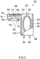
- FIG. 3 shows the base member 32 according to the embodiment in a side view, with parts of the drawing are shown in an outbreak diagram.
- a transformer chamber 52 of the base member 32 a transformer 54 is completely received.
- the transformer 54 has a transformer core 56 wrapped by a first winding 58, the secondary winding 58 and the transformer core 56 are enclosed by a transformer housing 60 having an approximately elliptical cross-section.
- the transformer 60 is converted into an in FIG. 3 overhead opening side 62 of the transformer chamber 52 introduced.
- the opening side lies approximately in the same plane as a ring top side 64 of the center contact ring 34 of the base element 32.
- a center contact element 66 for making electrical contact with the high-pressure discharge lamp 1 FIG. 1 and the transformer 54 is embedded in the base element 32 in such a way that a transformer contact region of the center contact element 66, not shown in this figure, contacts the transformer 54 and the lamp contact region 68 of the center contact element 66 in the center contact ring 34 for contacting the secondary winding 58 of the transformer 54 inside the transformer chamber 52 is arranged.
- the arrangement of the center contact element 66 will be explained in more detail in the figures described below.
- the center contact ring 34 is in the region of the lamp contact region 68 of the center contact element 66 for welding to the power supply 10 of the high-pressure discharge lamp 1 from FIG. 1 towards the ring top 64 open.
- the lamp contact region 68 of the center contact element 66 also has to carry out the power supply 10 from FIG. 1 a through opening 72 extending along a ring axis 70 of the center contact ring 34.
- In the passage opening 72 opens from a ring bottom 75 along the ring axis 70 extending and to the through hole 72 toward tapering funnel 76.
- the funnel 76 is used for easy recording of the power supply 10 from FIG. 1 during assembly of the high pressure discharge lamp 1.
- annular spring 78 extending around the ring axis 70 and an annular energy directing device 80 having a larger diameter are formed with a pointed cross-section.
- the energy director 80 is used for ultrasonic welding.
- One of the opening side 62 of the transformer chamber 52 opposite contacting side 82 has two down in FIG. 3 cantilevered and mutually offset dowel pins 84, 86, a fixing of the base member 32 on the board 50 in FIG. 2 support.
- the base element 32 from the FIG. 3 is a plastic injection molded component of polyphenylene sulfide (PPS).
- PPS polyphenylene sulfide
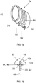
- FIG. 4a shows the transformer 54 in a perspective view.
- a ribbon winding of copper surrounding the transformer housing 60 serves as a second winding or as a primary winding 88 of the transformer 54.
- a round wire would also be conceivable as a primary winding 88.
- the elliptical cross-section transformer housing 60 has a length which is greater than the maximum height.
- Two contact pins 90, 92 collar of one Main vertex of the transformer housing 60 radially outward in a common direction, wherein the contact pins 90 and 92 each define a winding end 94 and 96 of the primary winding 88 on the transformer housing 60 and electrically contact.
- FIG. 4b is a coil end 94, 96 with a contact pin 90, 92 made FIG. 4a enlarged shown in a cross-sectional view.
- the contact pins 90, 92 are used in pin recesses 98 of the transformer housing 60, for example, self-locking by means of a press fit or by gluing.
- a clamping collar 100 is formed, which has an approximately flat and the PinlHarsachse 99 of the contact pins 90, 92 vertically formed clamping surface 102.
- the winding ends 94, 96 of the primary winding 88 are respectively clamped.
- the winding ends 94, 96 each have a through opening 106, through which the respective contact pin 90 and 92 is passed.
- the coil ends 94 and 96 may be soldered to the respective contact pins 90 and 92, respectively.
- the winding ends 94, 96 and thus the primary winding 88 are thus fixed by the contact pins 90, 92 force, material and / or positive and electrically contacted. In this way, the primary winding 88 can be wound in the manufacturing process with a lower accuracy compared to the prior art, since a fixation of the primary winding 88 on the transformer housing 60, which is carried out solely by the winding, is no longer necessary.
- the primary winding 88 is through the contact pins 90, 92 extremely robust and has a high mechanical strength, whereby the transformer 54 is bulk material capable and not, as in the prior art, must be included for protection in so-called transformer trays, which cause high additional costs, since on the one hand consuming equipped with transformers and on the other hand must be regularly subjected to a cleaning to remove dust and material residues. Due to the bulk material capability of the transformer 54 transport and storage costs are significantly reduced compared to the prior art, the handling in the manufacturing process is simplified and the manufacture and assembly is safer.
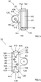
- FIG. 5 shows the base member 32 in a plan view in the direction of the opening side 62 FIG. 3 according to the embodiment.
- the tongue-shaped lamp contact region 68 of the center contact element 66 extends in the FIG. 5 approximately obliquely down to a longitudinal side 108 of the transformer chamber 52, on which the center contact ring 34 is formed.
- a center section 110 of the center contact element 66 is embedded substantially in the longitudinal side 108 and extends up to one in FIG. 5 the lower transverse side 112 of the transformer chamber 52.
- the center contact element 66 projects on the longitudinal side 108 with a transformer contact region 114 approximately along the transverse side 112 into the transformer chamber 52.
- a winding end 116 of the secondary winding 58 (see FIG. 3 ), out led to the transformer housing 60 and is electrically connected to the transformer contact area 114, for example in the form of a weld.
- the center contact element 66 consists for example of X5CrNi1810 and is integrated as an insert into the base element 32 produced by plastic injection molding.
- the center contact ring 34 is formed substantially centrally in the longitudinal direction of the longitudinal side 108 of the transformer chamber 52.
- the connecting region of the center contact ring 34 with the longitudinal side 108 is reinforced via a connecting web 118.
- the longitudinal side 108 of the transformer chamber 52 is widened in the region of the center section 110 of the center contact element 66 in order to sufficiently embed the center contact element 66.
- the center contact ring 34 has a circular inner portion 120 stepped back from the ring top 64, whereby the lamp contact area 68 of the center contact element 66 is exposed.
- FIG. 6 shows a bottom view of the base member 32 according to the embodiment.
- the staggered arrangement of the dowel pins 84, 86 on the contacting side 82 of the base member 32 can be seen.
- Contact plates 122, 124 are for electrically contacting the contact pins 90, 92 of the transformer 54 FIG. 4a arranged on the contacting side 82 of the base member 32.
- the contact plates 122, 124 are introduced into the contacting side 82 in such a way that the contacting side 82 has approximately a flat surface, in particular for surface contact with the circuit board 50 FIG.
- the contact pins 90 and 92 are passed through the contacting side 82 and are each soldered with mutually facing contact tongues 130 and 132 of the contact plates 122 and 124, respectively.
- the contact tongues 130 and 132 each have a passage opening 134 or 136 for easy reception of the contact pins 90, 92.
- the projecting contact portions 127 and 128 of the respective contact plates 122 and 124 are laterally bounded in sections by fixing elements 140, 142 formed on transverse sides 112, 138 of the base element 32. Due to the fixing elements 140, 142, the contact plates 122, 124 are better protected against mechanical stresses which occur, for example, during the assembly of the base element 32, with which the base element 32 can be pourable.
- the fixing elements 140, 142 are also in the FIG. 5 seen.
- the contact plates 122, 124 are either mounted after the plastic injection molding of the base member 32 or alternatively injected as inserts.
- the clamping collar 100 of the contact pins 90, 92, see FIG. 4a In addition to the fixation of the primary winding 88 additionally serve as a spacer element for spacing the primary winding 88 in the inserted state in the base element 32 of an inner wall 143 of the transformer chamber 52 in the FIG. 3 ,
- the space between the inner wall 143 of the transformer chamber 52 and the transformer 54 with a casting material such as a cost-effective silicone rubber, such as Elastosil RT 745 S from. Wacker Chemie, shed.
- a casting material such as a cost-effective silicone rubber, such as Elastosil RT 745 S from. Wacker Chemie, shed.
- the base member 32 and the transformer are made FIG. 3 with a Grundierwerkstoff, for example, intended for RTV2 silicones G790 the Fa. Wacker Chemie, primed and the winding end 116 of the secondary winding 58 from FIG. 3 and 5 soldered to the transformer contact region 114 of the center contact element 66.
- the potting material can easily, for example, a ten times higher thermal expansion than the lamp cap 14 from FIG.
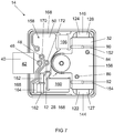
- FIG. 7 is the lamp base 14 according to the embodiment in a bottom view without socket cover with the board 50, the base member 32 and the socket 42 shown.
- the base member 32 is welded to the board 50 via the cantilevered contact portions 127, 128 of the contact plates 122, 124 with resistance spot welding, or alternatively laser welding.
- the welding areas 144, 146 required for this purpose lie between the contacting side 82 of the base element 32 FIG. 6 By the welding, the base member 32 is mechanically connected to the circuit board 50 on the one hand, and on the other hand, the primary winding 88 of the transformer 54 from FIG. 3 electrically contacted with the board 50.
- the circuit board 50 has expansion joints 152, 154 in the region of the contact pins 90, 92 of the base element 32. These extend substantially finger-like vertically from one in the FIG. 7 For example, changes in volume of the circuit board 50 due to temperature fluctuations in the operation of the high-pressure discharge lamp 1 from the expansion joints 152, 154 from the right board side 156 approximately in the area below the base element FIG. 1 or expansions of the Silikonvergusses of the base member 32, which are transmitted for example via the welded contact portions 127, 128 on the board 50, are compensated.
- Another function of the expansion joints 152, 154 is that they can accommodate the contact pins 90, 92, if they are from the contacting side 82 of the base member 32, see FIG. 6 , cantilever, bringing a roughly planar support opportunity the contacting side 82 on the board 50 is made possible also in this case.
- dowel pins 84, 86 which in the FIG. 7 are arranged approximately in the vicinity of the welding areas 146, 148, with the board 50, a relief of the welding areas 146, 148 of thermal and dynamic forces of change between the base member 32 and the board 50 is made possible.
- FIGS. 7 and 2 It can be seen that an easily accessible from the outside space 158 is essentially delimited by the board 50, by the lateral surface portion 40 of the lamp cap 14, the central dome 28 and the base member 32. About the space 158, the board 50 can be easily equipped with electrical components.
- the electrical components used here are, for example, a capacitor 160, which in the FIG. 7 is mounted approximately below the central dome 28 on the board 50 and how out FIG. 2 Visible about half the height of the base member 32, resistors 162, a suppressor diode 164 and various other electronic components 166.
- the board 50 also offers a significant surface potential to integrate further components, such as a throttle, not shown, which can be arranged between the contacting points 170, 172.
- the return conductor or the power supply 12 of the halogen discharge lamp 1 off FIG. 1 is passed through the contact point 172 as a pin-in-hole connection and is additionally welded to the board 50 via this.
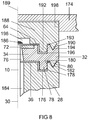
- FIG. 8 shows in a side view a cross section through the middle dome 28, the base member 32 and a base cover 174 according to the embodiment for more accurate representation of the connection between these components.
- the center dome 28 has to receive the annular spring 78 of the center contact ring 34 of the base member 32 has an annular groove 176 on the Domstirn nature 36, which is designed such that the annular spring 78 substantially abuts only with a ring outer surface 178 on a Nutwandungs character 180 and thus the annular spring 78 and the annular groove 176 form a fit.
- the point-shaped energy directors 80 of the center contact ring 34 completely fills a receiving groove 182 which is likewise pointed-shaped on the dome end face 36 of the central dome 28.
- the center contact ring 34 can be welded to the central dome 28 via an ultrasonic welding process.
- ultrasound welding leads to a high high-voltage strength of the connection point and, on the other hand, low geometric manufacturing tolerances can be achieved as a result.
- the load due to the high-frequency ultrasonic vibrations is effective only in the region of the center contact ring 34.
- the silicone potting in the Transformer chamber 52 off FIG. 3 Due to its high inertia, it does not carry the ultrasonic vibrations. Is the discharge vessel 4 off FIG.
- connection between the energy directing device 80 and the receiving groove 182 can also be realized, for example, with an adhesive joint with a 2K epoxy resin, such as DeloDuopox from Delo.
- the middle dome 28 in FIG. 5 has a power supply channel 184 for receiving the power supply 10 of the discharge vessel 4 from FIG. 1 with the power supply channel 184 extending along the base longitudinal axis 30 of the central dome 28 and leading to the funnel 76 of the center contact ring 34.
- the power supply 10 is passed through the power supply channel 184 and the funnel 76 through the through hole 72 of the center contact element 66 and welded by a welding tip 186 with the center contact element 66 and thus electrically contacted and mechanically connected.
- the base cover 174 is in the FIG. 5 only partially shown. This is fixedly connected via a cylindrical cover spacer 188 with the center contact ring 34.
- the cover intermediate piece axis 189 lies approximately on the base longitudinal axis 30 of the central dome 28.
- an energy directors 190 and an annular spring 192 are in a receiving groove 194 and an annular groove 196 which are respectively formed on the ring top 64 of the center contact ring 34 and the receiving groove 182 and the annular groove 176 of the central dome 28 correspond.
- the receiving groove 194 and the annular groove 196 are only in this FIG. 8 shown.
- a receiving region 196 is centered back from the middle of the intermediate piece underside 193, by means of which the welding tip 186 is receivable and thus spaced from the cover intermediate piece 188.
- the welding with the welding tip 186 is isolated by the cover spacer 188 and the socket cover 174 high-voltage resistant.
- the cover spacer 188 is inserted into a cylindrical recess 198 of the base lid 174 and firmly connected to this example by adhesive.
- the socket cover 174 is made of inexpensive plastic such as PA66, and the cover spacer 188 made of PPS corresponding to the socket member 32.
- the assembled board 50 in FIG. 7 is on the pin-in-hole connections of the contact pins 46, 48 of the socket 42 and the power supply 12 of the high pressure discharge lamp 1 from FIG. 1 and the welding areas 144, 146 of the base member 32 fixed.
- a so-called hot caulking for fixing the board, as in the prior art, can be omitted.
- a multi-part lamp cap with a separate base element, wherein in the base element, a transformer is accommodated, in which at least one winding is fixed via a contact pin.
Landscapes
- Engineering & Computer Science (AREA)
- Power Engineering (AREA)
- Fastening Of Light Sources Or Lamp Holders (AREA)
- Arrangement Of Elements, Cooling, Sealing, Or The Like Of Lighting Devices (AREA)
Description
- Die Erfindung betrifft ein Lampensockelelement mit einem Transformator gemäß dem Oberbegriff des Patentanspruchs 1, einen Lampensockel mit einem derartigen Lampensockelelement und eine Entladungslampe mit einem derartigen Lampensockel.
- In der
EP 1 511 131 A1 ist ein Transformator offenbart, der in einem Lampensockel für eine Hochdruckentladungslampe aufgenommen ist. Der Transformator hat eine Primärwicklung, die um ein Transformatorgehäuse gewickelt ist, wobei die Wicklungsabgänge weg von dem Transformatorgehäuse weisen. Eine Sekundärwicklung des Transformators ist innerhalb des Transformatorgehäuses angeordnet, wobei die Wicklungsabgänge durch das Transformatorgehäuse nach außen geführt sind. Nachteilig hierbei ist, dass die Wicklungsabgänge der Primär- und Sekundärwicklung des Transformators eine geringe mechanische Steifigkeit aufweisen und deswegen zum Schutz gegen äußere mechanische Einflüsse, vor der Montage in den Lampensockel, beispielsweise in sogenannten Transformatorentrays kostenaufwendig gelagert sind. Ein weiterer Nachteil sind die hohen Materialkosten, da der gesamte Lampensockel und der Transformator, wegen der hohen im Betrieb der Hochdruckentladungslampe auftretenden Temperaturen, aus einem hochtemperaturbeständigen und kostenintensiven Kunststoff bestehen. - Die
DE 195 21 070 A1 offenbart einen Hochspannungstransformator und eine Entladungslampenschaltung. Der Hochspannungstransformator weist einen Kern, eine Primärwicklung, eine Sekundärwicklung, eine Grundplatte und Isolationsmaterial, das den Kern und die Sekundärwicklung bedeckt, sowie einen leitenden Halter auf, der als Primärwicklung dient. DieDE 10 2006 014 695 A1 beschreibt ein Verfahren zur Herstellung eines elektrisch isolierenden Vergusskörpers und einen Sockel für eine Lampe. - Die Aufgabe der vorliegenden Erfindung ist es, ein Lampensockelelement, einen Lampensockel und eine Entladungslampe zu schaffen, die kostengünstig herstellbar und robust gegen äußere Einflüsse sind.
- Diese Aufgabe wird durch ein Lampensockelelement mit den Merkmalen des Patentanspruchs 1, einen Lampensockel mit den Merkmalen des Patentanspruchs 9 und eine Entladungslampe mit den Merkmalen des Patentanspruchs 16 gelöst.
- Besonders vorteilhafte Ausgestaltungen finden sich in den abhängigen Ansprüchen.
- Der Transformator des erfindungsgemäßen Lampensockelelements zur Montage in einem Lampensockel weist ein Transformatorgehäuse auf, das einen mit einer ersten Wicklung versehenen Transformatorkern umschließt. Um das Transformatorgehäuse herum ist eine zweite Wicklung angeordnet, die vorteilhafter Weise mit zumindest einem Kontaktelement an dem Transformatorgehäuse festgelegt ist.
- Diese Lösung hat den Vorteil, dass der Transformator eine hohe mechanische Festigkeit aufweist, insbesondere im Bezug auf die zweite Wicklung, wodurch der Transformator schüttgutfähig sein kann.
- Das Kontaktelement ist als in eine Aufnehmung des Transformatorgehäuses vorzugsweise selbsthemmend aufgenommener Kontaktpin ausgebildet. Die zweite Wicklung des Transformators kann dabei beispielsweise von zwei Kontaktpins mechanisch fixiert und elektrisch kontaktiert sein. Hierdurch ist die zweite Wicklung des Transformators einfach fixierbar und sehr robust.
- Die zweite Wicklung kann als Flachbandwicklung ausgeführt sein und an jeweiligen Wicklungsenden Fixierausnehmungen aufweisen, durch welche die Kontaktpins hindurch geführt sind. Eine derartige Flachbandwicklung ist einfach herstell- und an den Transformator montierbar.
- Zweckmäßig ist, wenn die Kontaktpins jeweils in etwa mittig einen Klemmkragen aufweisen und die Flachbandwicklung zwischen den Klemmkragen und dem Transformatorgehäuse angeordnet ist, wodurch die Flachbandwicklung mechanisch äußerst robust festgelegt ist.
- Vorteilhaft weist das Transformatorgehäuse einen etwa ellipsenförmigen Querschnitt auf, wobei die Länge des Transformatorgehäuses größer als die maximale Höhe ist.
- Zur einfachen Montage des Transformators mit einem Lampensockel können die Kontaktpins vom Hauptscheitel des Transformatorgehäuses radial nach außen in die gleiche Richtung weisen.
- Erfindungsgemäß ist ein Lampensockelelement zur Aufnahme eines Transformators vorgesehen. Diese Lösung hat den Vorteil, dass das Lampensockelelement und der Transformator als separates Bauteil von einem Lampensockel im Wesentlichen mechanisch entkoppelt sind, und beispielsweise aus einem kostengünstigeren Kunststoff mit einem höheren Wärmeausdehnungskoeffizienten herstellbar sind. Weiterhin hat das Lampensockelelement zum Schutz des Transformators eine den Transformator vollständig aufnehmende Transformatorkammer.
- Die Kontaktpins des Transformators sind dabei durch eine einer Öffnungsseite gegenüberliegenden Kontaktierungsseite der Transformatorkammer hindurch geführt, um ein einfaches Kontaktieren beispielsweise mit einer Platine zu ermöglichen.
- In einer vorteilhaften Ausgestaltung der Erfindung wird ein Mittenkontaktelement in der Transformatorkammer derart eingebracht, so dass ein Transformatorkontaktbereich des Mittenkontaktelements zur Kontaktierung der aus dem Transformatorgehäuse geführten ersten Wicklung des Transformators innerhalb und ein Lampenkontaktbereich des Mittenkontaktelements, insbesondere zur Kontaktierung einer Hochdruckentladungslampe, außerhalb der Transformatorkammer angeordnet wird.
- Zur elektrischen Isolierung kann vorteilhafterweise ein Kammerinnenraum der Transformatorkammer des Lampensockelelements nach der Aufnahme des Transformators mit einem Vergusswerkstoff ausgegossen sein.
- Der Vergusswerkstoff ist beispielsweise ein kostengünstiger Silikonkautschuk.
- Die Transformatorkammer hat vorteilhafter Weise eine die Öffnungsseite begrenzende Mantelfläche, die zwei Längsseiten und zwei Querseiten aufweist, wobei die Seiten im Wesentlichen rechteckig zueinander angeordnet sind.
- Bei einer vorteilhaften Ausgestaltung ist der Lampenkontaktbereich des Mittenkontaktelements in einem Mittenkontaktring aufgenommen, der mittig in Längsrichtung der Längsseite der Transformatorkammer derart an die Längsseite angeformt ist, dass eine Ringachse des Mittenkontaktrings sich in etwa parallel zu den Kontaktpins des Transformators erstreckt und eine Ringoberseite des Mittenkontaktrings in etwa bündig mit der Öffnungsseite der Transformatorkammer abschließt. Hierdurch ist der Transformator beim Einbau des Lampensockelelements in den Lampensockel einfach mit beispielsweise einer Hochdruckentladungslampe kontaktierbar.
- In etwa mittig von dem Mittenkontaktring kann ein Trichter ausgebildet sein, der sich entlang der Ringachse in Richtung der von der Transformatorkammer weg weisenden Flächennormalen der Öffnungsseite bis zum Lampenkontaktbereich des Mittenkontaktelements hin verjüngt. Durch den Trichter ist eine einfache Aufnahme beispielsweise einer Stromzuführung bei der Montage einer Hochdruckentladungslampe ermöglicht.
- Vorteilhafterweise bildet der Mittenkontaktring an einer Ringunterseite eine Ringfeder und einen einen größeren Radius als die Ringfeder aufweisenden ringförmigen Energierichtungsgeber jeweils zur Verbindung mit einem Lampensockel aus. Der Energierichtungsgeber kann zum einfachen Ultraschallverschweißen des Lampensockelelements mit dem Lampensockel dienen.
- An der Kontaktierungsseite der Transformatorkammer können die Kontaktpins von außen mit Kontaktplatten verbunden sein, die eine flächige Kontaktierungsmöglichkeiten mit beispielsweise einer Platine zur Verfügung stellen.
- Die Kontaktplatten ragen in Längsrichtung der Transformatorkammer jeweils abschnittsweise nach außen und können hierdurch einfach beispielsweise mit anderen Elementen in diesem Bereich verschweißt werden.
- Vorzugsweise können die Kontaktplatten jeweils abschnittsweise von der Querseite der Mantelfläche aus vorspringenden Fixierungselementen berandet sein, die als Schutz beispielsweise bei der Montage des Lampensockelelements mit dem Lampensockel dienen können.
- Zu einer einfachen Montage des Lampensockelelements mit dem Lampensockel kann an der Kontaktierungsseite des Lampensockelelements zumindest ein Passstift ausgebildet sein.
- Erfindungsgemäß hat ein Lampensockel, insbesondere zur Aufnahme einer Hochdruckentladungslampe, eine Trägerplatte. Hierbei kann an einer der Hochdruckentladungslampe abgewandte Trägerseite der Trägerplatte ein zylindrischer Mitteldom angeformt sein. An dem Mitteldom liegt dabei das Lampensockelelement mit der Ringunterseite an einer Mitteldomkopfseite in etwa an und ist an dem Mitteldom festgelegt. Durch diese Lösung ist ein mehrteiliger Lampensockel realisiert, der einfach montierbar und beispielsweise aus unterschiedlichen Werkstoffen bestehen kann.
- Eine Steckerbuchse kann kostengünstig seitlich an einem die Trägerplatte abschnittsweise umgebenden Mantelflächenabschnitt einstückig ausgebildet sein.
- In weiterer Ausgestaltung des Lampensockels können in dem Lampensockel eingebettete Kontaktpins einer Steckerbuchse aus der Trägerseite auskragen und in Ausnehmungen einer im Bereich der Trägerplatte angeordneten Platine einfach eingreifen, wodurch eine elektrische und mechanische Verbindung der Kontaktpins mit der Platine ermöglicht ist.
- Der zylindrische Mitteldom erstreckt sich vorzugsweise durch eine Platinenausnehmung der Platine hindurch.
- Zur einfachen elektrischen Kontaktierung des Transformators und zur Fixierung des Lampensockelelements mit dem Lampensockel können einfach die Kontaktplatten des Lampensockelelements mit der Platine elektrisch und mechanisch verbunden sein.
- Vorteilhafter Weise taucht die Ringfeder und der Energierichtungsgeber des Lampensockelelements in jeweils eine Ringnut des Mitteldoms ein, wodurch das Lampensockelelement mit dem Lampensockel durch ein Ultraschallschweißverfahren äußerst fest verbunden werden kann.
- Der Mitteldom kann beispielsweise einen Stromzuführungskanal aufweisen, der in den Trichter des Lampensockelelements mündet, um beispielsweise eine in den Stromzuführungskanal eingebrachten Stromzuführung der Hochdruckentladungslampe mit dem Mittenkontaktelement des Lampensockelelements zu verbinden.
- Der Lampensockel kann mit einem Sockeldeckel umschlossen sein, wobei der Sockeldeckel eine Ringfeder und einen ringförmigen Energierichtungsgeber ausbildet, die jeweils in eine Ringnut des Lampensockelelements eingetaucht sind. Durch die Ringfeder und den Energierichtungsgeber kann der Sockeldeckel einfach mit dem Lampensockel verbunden werden.
- Zweckmäßig ist es, wenn die Platine im Bereich der Kontaktpins des Lampensockelelements Dehnungsfugen aufweist, wodurch Volumenänderungen der Platine und oder des Lampensockelelements aufgrund von Temperaturschwankungen einfach ausgeglichen werden können.
- Zur Lagefixierung taucht zumindest ein Passstift des Lampensockelelements in zumindest eine Stiftaufnahme der Platine.
- Eine einfach herstellbare erfindungsgemäße Entladungslampe weist den oben beschriebenen Lampensockel auf.
- Im Folgenden soll die Erfindung anhand eines Ausführungsbeispiels näher erläutert werden. Die Figuren zeigen:
- Fig. 1
- Eine Seitenansicht einer Hochdruckentladungslampe gemäß einem Ausführungsbeispiel der Erfindung.
- Fig. 2
- Eine Seitenansicht eines Lampensockels gemäß dem Ausführungsbeispiel.
- Fig. 3
- Eine Seitenansicht eines Lampensockelelements gemäß dem Ausführungsbeispiel.
- Fig. 4a
- Eine perspektivische Ansicht eines Transformators gemäß dem Ausführungsbeispiel.
- Fig. 4b
- Einen Ausschnitt des Transformators aus
Fig. 4a in einer Schnittansicht. - Fig. 5
- Eine Draufsicht auf das Lampensockelelement gemäß dem Ausführungsbeispiel.
- Fig. 6
- Eine Untersicht auf das Lampensockelelement gemäß dem Ausführungsbeispiel.
- Fig. 7
- Eine Draufsicht auf den Lampensockel gemäß dem Ausführungsbeispiel.
- Fig. 8
- Eine Seitenansicht des Lampensockels gemäß dem Ausführungsbeispiel.
-
Figur 1 zeigt eine Seitenansicht auf eine Hochdruckentladungslampe 1 gemäß einem bevorzugten Ausführungsbeispiel, welche vorzugsweise für einen Kraftfahrzeugscheinwerfer verwendet wird. Diese weist ein von einem gläsernen Außenkolben 2 umschlossenes Entladungsgefäß 4 aus Quarzglas mit darin angeordneten Elektroden 6, 8 zum Erzeugen einer Gasentladung auf. Die Elektroden 6 und 8 sind jeweils mit einer aus dem Entladungsgefäß 4 heraus geführten Stromzuführung 10 bzw. 12 zur Versorgung mit elektrischer Energie verbunden. - Der Außenkolben 2 und das Entladungsgefäß 4 sind an einem Lampensockel 14 angesetzt, der mit einem in der
Figur 1 nicht dargestellten Lampensockelelement, in das ein Transformator eingebracht ist, ausgebildet ist. -
Figur 2 zeigt den Lampensockel 14 ausFigur 1 gemäß dem Ausführungsbeispiel quasi auf den Kopf gestellt, wobei der Lampensockel 14 ohne einen Sockeldeckel dargestellt ist. Der Lampensockel 14 bildet an seiner inFigur 2 unteren Sockelseite 16 einen Referenzring 18 mit nach unten auskragenden Haltefahnen 20 zur Lagefixierung der Hochdruckentladungslampe 1 ausFigur 1 aus. Der Referenzring 18 ist dabei über einen zylindrischen Steg 22 auf der den Haltefahnen 20 gegenüberliegenden Seite mit einer Trägerplatte 24 des Lampensockels 14 verbunden. Die Trägerplatte 24 weist auf ihrer dem Referenzring 18 abgewandten Trägerseite 26 einen in etwa mittig angeordneten zylinderförmigen Mitteldom 28 auf, der sich im Wesentlichen entlang der Sockellängsachse 30 erstreckt. Ein Lampensockelelement bzw. Sockelelement 32, das in der folgendenFigur 3 näher erläutert wird, ist über einen an dem Sockelelement 32 ausgebildeten Mittenkontaktring 34 mit einer Domstirnfläche 36 des Mitteldoms 28 verbunden. - Die Trägerplatte 24 hat einen in etwa rechteckförmigen Umfang, wobei an einem in der
Figur 2 linken Mantelflächenabschnitt 40 des Lampensockels 14 eine Steckerbuchse 42 zur elektrischen Kontaktierung der Hochdruckentladungslampe 1 einstückig ausgebildet ist. Die Steckerbuchse 42 kragt dabei in etwa auf der Höhe des Mittenkontaktrings 34 des Sockelelements 32 nach außen. Eine Steckeraufnahme der Steckerbuchse 42 ist von der inFigur 2 linken Stirnseite 44 der Steckerbuchse 42 zugänglich. In den Lampensockel 14 sind Kontaktpins 46, 48 eingebettet, die sich von der Steckerbuchse 42 über den Mantelflächenabschnitt 40 und die Trägerplatte 24 erstrecken und etwa zwischen dem Mantelflächenabschnitt 40 und dem Mitteldom 28 aus der Trägerseite 26 der Trägerplatte 24 im Wesentlichen parallel zur Sockellängsachse 30 auskragen. Die Drahtlängen der Kontaktpins können insgesamt unterschiedlich sein, so dass der inFigur 2 rechte Kontaktpin 48 beispielsweise einen größeren Abstand zum Mantelflächenabschnitt 40 aufweist. - Im Wesentlichen im Parallelabstand zu der Trägerseite 26 der Trägerplatte 24 des Lampensockels 14 ist ein Lead-Frame bzw. eine Platine 50 angeordnet. Diese weist zwei in dieser Figur nicht sichtbare Ausnehmungen auf, durch die die Kontaktpins 46, 48 hindurch geführt sind und somit zwischen der Platine 50 und den Kontaktpins 46, 48 eine sogenannte Pin-in-Hole Verbindung ausgeführt ist. Die Kontaktpins 46, 48 sind dabei entweder selbsthemmend in die Ausnehmungen der Platine 50 eingebracht oder werden zusätzlich mit der Platine 50 beispielsweise verschweißt. Die Platine 50 hat mittig einen in dieser Figur ebenfalls nicht sichtbaren Ausnehmungsbereich, durch welchen der Mitteldom 28 hindurch geführt ist. Zusätzlich zu den Kontaktpins 46, 48 wird die Platine 50 durch das Sockelelement 32 lagefixiert, was untenstehend in den folgenden Figuren näher erläutert ist.
-
Figur 3 zeigt das Sockelelement 32 gemäß dem Ausführungsbeispiel in einer Seitenansicht, wobei Teile der Zeichnung in einer Ausbruchsdarstellung abgebildet sind. In einer Transformatorkammer 52 des Sockelelements 32 ist ein Transformator 54 vollständig aufgenommen. - Der Transformator 54 hat einen Transformatorkern 56, der von einer ersten Wicklung bzw. Sekundärwicklung 58 umwickelt ist, wobei die Sekundärwicklung 58 und der Transformatorkern 56 von einem einen in etwa ellipsenförmigen Querschnitt aufweisenden Transformatorgehäuse 60 umschlossen sind.
- Der Transformator 60 wird über in eine in
Figur 3 oben liegende Öffnungsseite 62 der Transformatorkammer 52 eingebracht. Die Öffnungsseite liegt dabei in etwa in einer gleichen Ebene wie eine Ringoberseite 64 des Mittenkontaktrings 34 der Sockelelements 32. - Ein Mittenkontaktelement 66 zur elektrischen Kontaktierung von der Hochdruckentladungslampe 1 aus
Figur 1 und des Transformators 54 ist derart in das Sockelelement 32 eingebettet, dass ein in dieser Figur nicht dargestellter Transformatorkontaktbereich des Mittenkontaktelements 66 zur Kontaktierung der aus dem Transformatorgehäuse 60 geführten Sekundärwicklung 58 des Transformators 54 innerhalb der Transformatorkammer 52 und ein Lampenkontaktbereich 68 des Mittenkontaktelements 66 im Mittenkontaktring 34 angeordnet ist. Die Anordnung des Mittenkontaktelements 66 wird in den weiter unten beschriebenen Figuren genauer erläutert. Der Mittenkontaktring 34 ist im Bereich des Lampenkontaktbereichs 68 des Mittenkontaktelements 66 zum Verschweißen mit der Stromzuführung 10 der Hochdruckentladungslampe 1 ausFigur 1 zur Ringoberseite 64 hin offen. - Der Lampenkontaktbereich 68 des Mittenkontaktelements 66 weist ferner zur Durchführung der Stromzuführung 10 aus
Figur 1 eine sich entlang einer Ringachse 70 des Mittenkontaktrings 34 erstreckende Durchgangsöffnung 72 auf. In der Durchgangsöffnung 72 mündet ein sich von einer Ringunterseite 75 sich entlang der Ringachse 70 erstreckender und zu der Durchgangsöffnung 72 hin verjüngender Trichter 76. Der Trichter 76 dient zur einfachen Aufnahme der Stromzuführung 10 ausFigur 1 bei der Montage der Hochdruckentladungslampe 1. - An der Ringunterseite 75 des Mittenkontaktrings 34 sind zur Verbindung mit dem Mitteldom 28 des Lampensockels 14 aus
Figur 2 eine sich jeweils um die Ringachse 70 erstreckende Ringfeder 78 und ein einen größeren Durchmesser aufweisender ringförmiger Energierichtungsgeber 80 mit einem spitzförmigen Querschnitt ausgebildet. Der Energierichtungsgeber 80 dient dabei zum Ultraschallverschweißen. - Eine der Öffnungsseite 62 der Transformatorkammer 52 gegenüberliegende Kontaktierungsseite 82 hat zwei nach unten in
Figur 3 auskragende und zueinander versetzte Passstifte 84, 86, die eine Fixierung des Sockelelements 32 auf der Platine 50 inFigur 2 unterstützen. - Das Sockelelement 32 aus der
Figur 3 ist beispielsweise ein Kunststoff-Spritzgussbauteil aus Polyphenylensulfid (PPS). -
Figur 4a zeigt den Transformator 54 in einer perspektivischen Ansicht. Eine das Transformatorgehäuse 60 umwickelnde Flachbandwicklung aus Kupfer dient als eine zweite Wicklung bzw. als eine Primärwicklung 88 des Transformators 54. Anstelle des Flachbands wäre auch ein Runddraht als Primärwicklung 88 denkbar. - Das einen ellipsenförmigen Querschnitt aufweisende Transformatorgehäuse 60 hat eine Länge die größer als die maximale Höhe ist. Zwei Kontaktpins 90, 92 kragen von einem Hauptscheitel des Transformatorgehäuses 60 radial nach außen in eine gemeinsame Richtung aus, wobei die Kontaktpins 90 und 92 jeweils ein Wicklungsende 94 bzw. 96 der Primärwicklung 88 am Transformatorgehäuse 60 festlegen und elektrisch kontaktieren.
- In der
Figur 4b ist ein Wicklungsende 94, 96 mit einem Kontaktpin 90, 92 ausFigur 4a vergrößert in einer Querschnittansicht dargestellt. Die Kontaktpins 90, 92 sind in Stiftausnehmungen 98 des Transformatorgehäuses 60 beispielsweise selbsthemmend mittels einer Presspassung oder durch verkleben eingesetzt. In etwa mittig in Bezug auf eine Pinlängsachse 99 der Kontaktpins 90, 92 ist ein Klemmkragen 100 ausgebildet, der eine in etwa flache und zur Pinlängsachse 99 der Kontaktpins 90, 92 senkrecht ausgebildete Klemmfläche 102 hat. Zwischen der Klemmfläche 102 und dem Transformatorgehäuse 60 sind jeweils die Wicklungsenden 94, 96 der Primärwicklung 88 eingeklemmt. Die Wicklungsenden 94, 96 weisen dabei jeweils eine Durchgangsöffnung 106 auf, durch die der jeweilige Kontaktpin 90 und 92 hindurchgeführt ist. Für eine zusätzliche Fixierung können die Wicklungsenden 94 und 96 mit dem jeweiligen Kontaktpin 90 bzw. 92 verlötet werden. Die Wicklungsenden 94, 96 und somit die Primärwicklung 88 sind durch die Kontaktpins 90, 92 somit kraft-, stoff- und/oder formschlüssig fixiert und elektrisch kontaktiert. Hierdurch kann die Primärwicklung 88 im Fertigungsprozess auch mit einer geringeren Genauigkeit im Vergleich zum Stand der Technik gewickelt werden, da eine allein durch die Wicklung erfolgte Fixierung der Primärwicklung 88 am Transformatorgehäuse 60 nicht mehr notwendig ist. Die Primärwicklung 88 ist durch die Kontaktpins 90, 92 äußerst robust und weist eine hohe mechanische Festigkeit auf, wodurch der Transformator 54 schüttgutfähig ist und nicht, wie im Stand der Technik, zum Schutz in sogenannten Transformatorentrays aufgenommen werden muss, die hohe zusätzliche Kosten verursachen, da diese einerseits aufwendig mit Transformatoren bestückt und andererseits regelmäßig einer Reinigung zum Entfernen von Staub und Materialresten unterzogen werden müssen. Durch die Schüttgutfähigkeit des Transformators 54 werden Transport- und Lagerkosten deutlich im Vergleich zum Stand der Technik reduziert, die Handhabung im Fertigungsprozess ist vereinfacht und die Herstellung und Montage ist sicherer. -
Figur 5 zeigt das Sockelelement 32 in einer Draufsicht in Richtung der Öffnungsseite 62 ausFigur 3 gemäß dem Ausführungsbeispiel. Hierbei ist die Anordnung des Mittenkontaktelements 66 ersichtlich. Der zungenförmige Lampenkontaktbereich 68 des Mittenkontaktelements 66 erstreckt sich dabei in derFigur 5 in etwa schräg nach unten zu einer Längsseite 108 der Transformatorkammer 52, an der der Mittenkontaktring 34 ausgebildet ist. Anschließend an den Lampenkontaktbereich 68 ist ein Mittenabschnitt 110 des Mittenkontaktelements 66 im Wesentlichen in die Längsseite 108 eingebettet und erstreckt sich bis zu einer inFigur 5 unteren Querseite 112 der Transformatorkammer 52. Das Mittenkontaktelement 66 kragt an der Längsseite 108 mit einem Transformatorkontaktbereich 114 in etwa entlang der Querseite 112 in die Transformatorkammer 52 aus. Im Bereich des Transformatorkontaktbereichs 114 des Mittenkontaktelements 66 ist ein Wicklungsende 116 der Sekundärwicklung 58 (sieheFigur 3 ), aus dem Transformatorgehäuse 60 geführt und wird mit dem Transformatorkontaktbereich 114, beispielsweise in Form einer Verschweißung, elektrisch verbunden. - Das Mittenkontaktelement 66 besteht beispielsweise aus X5CrNi1810 und wird als Einlegeteil in das durch Kunststoffspritzguss hergestellte Sockelelement 32 integriert.
- Wie aus der
Figur 5 ersichtlich, ist der Mittenkontaktring 34 im Wesentlichen mittig in Längsrichtung der Längsseite 108 der Transformatorkammer 52 angeformt. Der Verbindungsbereich des Mittenkontaktrings 34 mit der Längsseite 108 ist über einen Verbindungssteg 118 verstärkt. Die Längsseite 108 der Transformatorkammer 52 ist im Bereich des Mittenabschnitts 110 des Mittenkontaktelements 66 verbreitert, um das Mittenkontaktelement 66 ausreichend einzubetten. - Der Mittenkontaktring 34 hat einen von der Ringoberseite 64 zurückgestuften kreisförmigen Innenabschnitt 120, wodurch der Lampenkontaktbereich 68 des Mittenkontaktelements 66 freiliegt.
-
Figur 6 zeigt eine Untersicht auf das Sockelelement 32 gemäß dem Ausführungsbeispiel. Hierbei ist die versetzte Anordnung der Passstifte 84, 86 an der Kontaktierungsseite 82 des Sockelelements 32 erkennbar. Kontaktplatten 122, 124 sind zur elektrischen Kontaktierung der Kontaktpins 90, 92 des Transformators 54 ausFigur 4a an der Kontaktierungsseite 82 des Sockelelements 32 angeordnet. Die Kontaktplatten 122, 124 sind derart in die Kontaktierungsseite 82 eingebracht, dass die Kontaktierungsseite 82 in etwa eine ebene Fläche aufweist, insbesondere zur flächigen Auflage auf die Platine 50 ausFigur 2 . An Querkanten 125 und 126 des Sockelelements 32 kragen die Kontaktplatten 122 und 124 von dem Sockelelement 32 mit einem Kontaktabschnitt 127 bzw. 128 nach außen, wobei diese Kontaktabschnitte 127, 128 zum Widerstandspunktverschweißen oder Laserschweißen mit der Platine 50 aus Figur 2 vorgesehen sind. Die Kontaktpins 90 und 92 sind durch die Kontaktierungsseite 82 hindurchgeführt und sind jeweils mit aufeinander zuweisenden Kontaktzungen 130 bzw. 132 der Kontaktplatten 122 bzw. 124 verlötet. Die Kontaktzungen 130 und 132 haben jeweils eine Durchgangsöffnung 134 bzw. 136 zur einfachen Aufnahme der Kontaktpins 90, 92. Durch die Verlötung der Kontaktpins 90, 92 wird die Transformatorkammer 52, sieheFigur 5 , hermetisch verschlossen. Die auskragenden Kontaktabschnitt 127 und 128 der jeweiligen Kontaktplatten 122 bzw. 124 werden von an Querseiten 112, 138 des Sockelelements 32 ausgebildeten Fixierungselementen 140, 142 abschnittsweise seitlich begrenzt. Durch die Fixierungselemente 140, 142 sind die Kontaktplatten 122, 124 vor mechanischen Belastungen, die beispielsweise bei der Montage des Sockelelements 32 auftreten, besser geschützt, womit das Sockelelement 32 schüttgutfähig sein kann. Die Fixierungselemente 140, 142 sind ebenfalls in derFigur 5 ersichtlich. Die Kontaktplatten 122, 124 werden entweder nach der Kunststoff-Spritzgussherstellung des Sockelelements 32 montiert oder alternativ als Einlegeteile mit eingespritzt. - Die Klemmkragen 100 der Kontaktpins 90, 92, siehe
Figur 4a , dienen neben der Fixierung der Primärwicklung 88 zusätzlich als Distanzelement zur Beabstandung der Primärwicklung 88 im eingesetzten Zustand in das Sockelelement 32 von einer Innenwandung 143 der Transformatorkammer 52 in derFigur 3 . - Durch die Kontaktierung der Kontaktplatten 122, 124 mit der Primärwicklung 88 des Transformators 54 aus
Fig. 6 über die Kontaktpins 90, 92 ist ein Laserschweissprozess mit der Primärwicklung 88 zur elektrischen Kontaktierung und direkten mechanischen Verbindung mit beispielsweise der Platine 50 ausFigur 2 wie im Stand der Technik nicht mehr notwendig, da die Primärwicklung 88 über die Kontaktplatten 122, 124 mit der Platine 50 kontaktiert werden kann. Durch den wegfallenden Laserschweissprozess ist eine aufwendige und kostenintensive für den Laserschweissprozess notwendige Nickelbeschichtung der Primärwicklung 88 überflüssig. - Zur elektrischen Isolierung des Transformators 54 in der Transformatorkammer 52 des Sockelelements 32 aus
Figur 3 wird der Raum zwischen der Innenwandung 143 der Transformatorkammer 52 und dem Transformator 54 mit einem Vergusswerkstoff, beispielsweise ein kostengünstiger Silikon-Kautschuk, wie Elastosil RT 745 S der Fa. Wacker Chemie, vergossen. Vor dem Verguss werden das Sockelelement 32 und der Transformator ausFigur 3 mit einem Grundierwerkstoff, beispielsweise der für RTV2-Silikone bestimmte G790 der Fa. Wacker Chemie, grundiert und das Wicklungsende 116 der Sekundärwicklung 58 ausFigur 3 und5 mit dem Transformatorkontaktbereich 114 des Mittenkontaktelements 66 verlötet. Der Vergusswerkstoff kann problemlos beispielsweise eine zehnfach höhere thermische Ausdehnung als der Lampensockel 14 ausFigur 2 aufweisen, da das den Vergusswerkstoff aufnehmende Sockelelement 32 von dem Lampensockel 14 größtenteils mechanisch abgekoppelt ist. InFigur 7 ist der Lampensockel 14 gemäß dem Ausführungsbeispiel in einer Untersicht ohne Sockeldeckel mit der Platine 50 dem Sockelelement 32 und der Steckerbuchse 42 gezeigt. Das Sockelelement 32 wird mit der Platine 50 über die auskragenden Kontaktabschnitte 127, 128 der Kontaktplatten 122, 124 mit Widerstandspunktschweißen oder alternativ mit Laserschweißen verschweißt. Die dazu erforderlichen Schweißbereiche 144, 146 liegen dabei zwischen der Kontaktierungsseite 82 des Sockelelements 32 ausFigur 6 und der Platine 50, im Wesentlichen im Bereich der auskragenden Kontaktabschnitte 127, 128. Durch die Schweißung wird das Sockelelement 32 zum Einen mechanisch mit der Platine 50 verbunden und zum Anderen wird die Primärwicklung 88 des Transformators 54 ausFigur 3 elektrisch mit der Platine 50 kontaktiert. - Die Platine 50 weist im Bereich der Kontaktpins 90, 92 des Sockelelements 32 Dehnungsfugen 152, 154 auf. Diese erstrecken sich im Wesentlichen fingerartig senkrecht von einer in der
Figur 7 rechten Platinenseite 156 etwa im Bereich unterhalb des Sockelelements 32. Durch die Dehnungsfugen 152, 154 können beispielsweise Volumenänderungen der Platine 50 aufgrund von Temperaturschwankungen im Betrieb der Hochdruckentladungslampe 1 ausFigur 1 oder Ausdehnungen des Silikonvergusses des Sockelelements 32, die beispielsweise über die verschweißten Kontaktabschnitte 127, 128 auf die Platine 50 übertragen werden, ausgeglichen werden. Eine weitere Funktion der Dehnungsfugen 152, 154 liegt darin, dass diese die Kontaktpins 90, 92 aufnehmen können, falls diese aus der Kontaktierungsseite 82 des Sockelelements 32, sieheFigur 6 , auskragen, womit eine in etwa planare Auflagemöglichkeit der Kontaktierungsseite 82 auf der Platine 50 auch in diesem Fall ermöglicht ist. - Durch formschlüssige Verbindung der an dem Sockelelement 32 ausgebildeten Passstifte 84, 86, die in der
Figur 7 in etwa in der Nähe der Schweißbereiche 146, 148 angeordnet sind, mit der Platine 50, ist eine Entlastung der Schweißbereiche 146, 148 von thermischen und dynamischen Wechselkräften zwischen dem Sockelelement 32 und der Platine 50 ermöglicht. - In der Zusammenschau der
Figuren 7 und2 ist ersichtlich, das ein von außen leicht zugänglicher Freiraum 158 im Wesentlichen von der Platine 50, von dem Mantelflächenabschnitt 40 des Lampensockels 14, dem Mitteldom 28 und dem Sockelelement 32 begrenzt ist. Über den Freiraum 158 kann die Platine 50 einfach mit elektrischen Bauteilen bestückt werden. Die hier verwendeten elektrischen Bauteile sind beispielsweise ein Kondensator 160, der in derFigur 7 in etwa unterhalb des Mitteldoms 28 auf der Platine 50 befestigt ist und wie ausFigur 2 erkennbar etwa die halbe Höhe des Sockelelements 32 aufweist, Widerstände 162, eine Supressor-Diode 164 und diverse andere elektronische Bauteile 166. In dem Bereich des Freiraums 158, wo die Kontaktpins 46, 48 aus der Platine 50 auskragen, ist ausreichend Platz, beispielsweise für ein Schneidmesser mit dem Durchmesser d = 10mm zum abschneiden diverser aus der Platine 50 auskragender Drähte, vorgesehen. Durch die großzügigen Abmessungen der Platine 50 und des Freiraums 158 ist es nicht notwendig, dass Leiterbahnen 168 aufgrund von Platzmangel zwischen beispielsweise Bauteilen 160 bis 166 und der Platine 50 hindurchgeführt werden. Die Platine 50 bietet ferner ein erhebliches Flächenpotential zur Integration weiterer Bauteile, wie beispielsweise einer nicht dargestellten Drossel, die zwischen den Kontaktierungspunkten 170, 172 angeordnet werden kann. - Der Rückleiter bzw. die Stromzuführung 12 der Halogenentladungslampe 1 aus
Figur 1 ist durch den Kontaktierungspunkt 172 als Pin-in-Hole Verbindung geführt und wird über diesen zusätzlich mit der Platine 50 verschweißt. -
Figur 8 zeigt in einer Seitenansicht einen Querschnitt durch den Mitteldom 28, dem Sockelelement 32 und einem Sockeldeckel 174 gemäß dem Ausführungsbeispiel zur genaueren Darstellung der Verbindung zwischen diesen Bauelementen. Der Mitteldom 28 hat zur Aufnahme der Ringfeder 78 des Mittenkontaktrings 34 des Sockelelements 32 eine Ringnut 176 an der Domstirnfläche 36, die derart ausgeführt ist, dass die Ringfeder 78 nur mit einer Ringaußenfläche 178 an einer Nutwandungsfläche 180 im Wesentlichen anliegt und somit die Ringfeder 78 und die Ringnut 176 ein Passung bilden. - Der spitzförmige Energierichtungsgeber 80 des Mittenkontaktrings 34 füllt vollständig eine an der Domstirnfläche 36 des Mitteldoms 28 ebenfalls spitzförmig ausgebildete Aufnahmenut 182 aus. Durch den Energierichtungsgeber 80 kann der Mittenkontaktring 34 mit dem Mitteldom 28 über ein Ultraschallschweißverfahren verschweißt werden. Das Ultraschallschweißen führt zum Einen zu einer hohen Hochvolt-Festigkeit der Verbindungsstelle und zum Anderen können hierdurch geringe Geometrische Herstellungstoleranzen erreicht werden. Die Belastung durch die hochfrequenten Ultraschallschwingungen ist nur im Bereich des Mittenkontaktrings 34 wirksam. Der Silikonverguss in der Transformatorkammer 52 aus
Figur 3 führt aufgrund seiner hohen Trägheit die Ultraschallschwingungen nicht mit. Ist das Entladungsgefäß 4 ausFigur 1 bereits mit dem Lampensockel 14 montiert, so ist aufgrund des geringen Ultraschall-Energieeintrags kaum eine Wechselwirkung mit dem Entladungsgefäß 4 vorhanden. Alternativ zum Ultraschallverschweißen kann die Verbindung zwischen dem Energierichtungsgeber 80 und der Aufnahmenut 182 auch beispielsweise mit einer Klebefuge mit einem 2K-Epoxydharz, wie DeloDuopox der Fa. Delo, realisiert werden. - Der Mitteldom 28 in
Figur 5 weist einen Stromzuführungskanal 184 zur Aufnahme der Stromzuführung 10 des Entladungsgefäßes 4 ausFigur 1 auf, wobei sich der Stromzuführungskanal 184 entlang der Sockellängsachse 30 des Mitteldoms 28 erstreckt und zu dem Trichter 76 des Mittenkontaktrings 34 hin mündet. Die Stromzuführung 10 ist dabei über den Stromzuführungskanal 184 und den Trichter 76 durch die Durchgangsöffnung 72 des Mittenkontaktelements 66 hindurchgeführt und durch eine Schweißkuppe 186 mit dem Mittenkontaktelement 66 verschweißt und somit elektrisch kontaktiert und mechanisch verbunden. - Der Sockeldeckel 174 ist in der
Figur 5 nur ausschnittsweise gezeigt. Dieser ist hierbei über ein zylinderförmiges Deckelzwischenstück 188 mit dem Mittelkontaktring 34 fest verbunden. Die Deckelzwischenstückachse 189 liegt dabei in etwa auf der Sockellängsachse 30 des Mitteldoms 28. Für die Verbindung des Deckelzwischenstücks 188 mit dem Sockelelement 32 ist ein Energierichtungsgeber 190 und eine Ringfeder 192, entsprechend wie bei dem Mittelkontaktring 34, an einer dem Mittelkontaktring 34 zuweisenden Zwischenstückunterseite 193 ausgebildet. Der Energierichtungsgeber 190 und die Ringfeder 192 sind dabei in einer Aufnahmenut 194 und einer Ringnut 196, die jeweils an der Ringoberseite 64 des Mittelkontaktrings 34 ausgebildet sind und der Aufnahmenut 182 und der Ringnut 176 des Mitteldoms 28 entsprechen, aufgenommen. Die Aufnahmenut 194 und die Ringnut 196 werden nur in dieserFigur 8 dargestellt. - Am Deckelzwischenstück 188 ist mittig von der Zwischenstückunterseite 193 her ein Aufnahmebereich 196 zurückgestuft, durch den die Schweißkuppe 186 aufnehmbar und somit von dem Deckelzwischenstück 188 beabstandet ist. Die Verschweißung mit der Schweißkuppe 186 ist durch das Deckelzwischenstück 188 und den Sockeldeckel 174 Hochvoltfest isoliert.
- Das Deckelzwischenstück 188 ist in eine zylindrische Ausnehmung 198 des Sockeldeckels 174 gesteckt und fest mit diesem beispielsweise durch Klebstoff verbunden.
- Der Sockeldeckel 174 besteht aus einem kostengünstigen Kunststoff, wie zum Beispiel PA66, und das Deckelzwischenstück 188 aus PPS entsprechend dem Sockelelement 32.
- Zum Verschließen des Lampensockels 14 ist dieser vollständig, wie in
Figur 1 ersichtlich von dem Sockeldeckel 174 umgeben. - Die bestückte Platine 50 in
Figur 7 ist über die Pin-in-Hole Verbindungen der Kontaktpins 46, 48 der Steckerbuchse 42 und der Stromzuführung 12 der Hochdruckentladungslampe 1 ausFigur 1 und den Schweißbereichen 144, 146 des Sockelelements 32 fixiert. Ein sogenanntes Heißverstemmen zur Fixierung der Platine, wie im Stand der Technik, kann entfallen. - Durch den einfachen und mehrteiligen Aufbau des Lampensockels 14 treten Toleranzverkettungen über drei oder vier einzelner Komponenten des Lampensockels 14 im Vergleich zum Stand der Technik kaum mehr auf.
- Offenbart ist ein mehrteilig aufgebauter Lampensockel mit einem separaten Sockelelement, wobei in dem Sockelelement ein Transformator aufgenommen ist, bei dem zumindest eine Wicklung über einen Kontaktpin fixiert ist.
Claims (16)
- Lampensockelelement (32) mit einem Transformator (54) mit einer den Transformator (54) aufnehmenden Transformatorkammer (52), wobei der Transformator (54) vollständig in der Transformatorkammer (52) aufgenommen ist und ein Transformatorgehäuse (60) aufweist, das einen mit einer ersten Wicklung (58) versehenen Transformatorkern (56) umschließt, und wobei um das Transformatorgehäuse (60) herum eine zweite Wicklung (88) angeordnet ist, die mit zumindest einem Kontaktelement (90, 92) an dem Transformatorgehäuse (60) festgelegt ist, dadurch gekennzeichnet, dass Kontaktpins (90, 92) des Transformators (54) durch eine einer Öffnungsseite (62) gegenüberliegenden Kontaktierungsseite (82) der Transformatorkammer (52) hindurchgeführt sind.
- Lampensockelelement nach Anspruch 1, wobei ein Mittenkontaktelement (66) in der Transformatorkammer (52) derart eingebracht ist, dass ein Transformatorkontaktbereich (114) des Mittenkontaktelements (66) zur Kontaktierung der aus dem Transformatorgehäuse (60) geführten ersten Wicklung (58) des Transformators (54) innerhalb und ein weiterer Lampenkontaktbereich (68), insbesondere zur Kontaktierung einer Hochdruckentladungslampe (1), außerhalb der Transformatorkammer (52) angeordnet ist.
- Lampensockelelement nach Anspruch 1 oder 2, wobei eine die Öffnungsseite (62) begrenzende Mantelfläche der Transformatorkammer (52) zwei Längsseiten (108) und zwei Querseiten (112, 138) aufweist, die im Wesentlichen rechtwinklig zueinander angeordnet sind.
- Lampensockelelement nach Anspruch 3, wobei der Lampenkontaktbereich (68) des Mittenkontaktelements (66) in einem Mittenkontaktring (34) aufgenommen ist, der mittig in Längsrichtung der Längsseite (108) der Transformatorkammer (52) derart an die Längsseite (108) angeformt ist, so dass eine Ringachse (70) sich in etwa parallel zu einem Kontaktpin (90, 92) des Transformators (54) erstreckt und eine Ringoberseite (64) in etwa bündig mit der Öffnungsseite (62) der Transformatorkammer (52) abschließt.
- Lampensockelelement nach Anspruch 4, wobei in etwa mittig von dem Mittenkontaktring (34) ein Trichter (76) ausgebildet ist, der sich entlang der Ringachse (70) in Richtung der Flächennormalen der Öffnungsseite (62) der Transformatorkammer (52) bis zum Lampenkontaktbereich (68) des Mittennkontaktelements (66) hin verjüngt.
- Lampensockelelement nach Anspruch 4 oder 5, wobei der Mittenkontaktring (34) an einher Ringunterseite (75) eine Ringfeder (78) und einen, einen größeren Radius als die Ringfeder (78) aufweisenden, ringförmigen Energierichtungsgeber (80) mit einem spitzförmigen Querschnitt jeweils zur Verbindung mit dem Lampensockel (14) ausbildet.
- Lampensockelelement nach einem der Ansprüche 1 bis 6, wobei von außen an der Kontaktierungsseite (82) der Transformatorkammer (52) die Kontaktpins (90, 92) mit Kontaktplatten (122, 124) in Verbindung stehen.
- Lampensockelelement nach einem der Ansprüche 1 bis 7, wobei an der Kontaktierungsseite (82) des Lampensockelelements (32) zumindest ein Passstift (84, 86) ausgebildet ist.
- Lampensockel, insbesondere zur Aufnahme einer Hochdruckentladungslampe (1), mit einer Trägerplatte (24), wobei an einer der Hochdruckentladungslampe (1) abgewandten Trägerseite (26) der Trägerplatte (24) ein zylindrischer Mitteldom (28) mittig angeformt ist, wobei ein Lampensockelelement (32) nach einem oder mehreren der Ansprüche 1 bis 8 mit der Ringunterseite (75) an einer Mitteldomkopfseite (36) in etwa anliegt und an dem Mitteldom (28) festgelegt ist.
- Lampensockel nach Anspruch 9, wobei in den Lampensockel (14) eingebettete Kontaktpins (46, 48) einer Steckerbuchse (42) aus der Trägerseite (26) auskragen und in Ausnehmungen einer im Parallelabstand zur Trägerplatte (24) angeordneten Platine (50) eingreifen, wobei sich der zylindrische Mitteldom (28) durch eine Platinenausnehmung der Platine (50) hindurch erstreckt.
- Lampensockel nach einem der Ansprüche 9 oder 10, wobei die Ringfeder (78) und der Energierichtungsgeber (80) des Lampensockelelements (32) in jeweils eine Ringnut (176) und eine Ringaufnahme (178) des Mitteldoms (28) eintauchen.
- Lampensockel nach einem der Ansprüche 9 bis 11, wobei der Mitteldom (28) einen eine Stromzuführung (10) aufnehmenden Stromzuführungskanal (184) aufweist, der sich entlang der Mittelachse (30) des Mitteldoms (28) erstreckt und zum Trichter (76) des Lampensockelelements (32) hin mündet.
- Lampensockel nach einem der Ansprüche 9 bis 12, wobei ein Sockeldeckel (174) den Lampensockel (14) umschließt, wobei der Sockeldeckel (174) zur mechanischen Verbindung mit dem Lampensockel (14) eine Ringfeder (192) und einen ringförmigen Energierichtungsgeber (190) ausbildet, die jeweils in eine Ringnut (196) und eine Ringaufnahme (194) des Lampensockelelements (32) eingetaucht sind.
- Lampensockel nach einem der Ansprüche 10 bis 13, wobei die Platine (50) im Bereich der Kontaktpins (90, 92) des Lampensockelelements (32) Dehnungsfugen (152, 154) aufweist.
- Lampensockel nach einem der Ansprüche 9 bis 14, wobei der zumindest eine Passstift (84, 86) des Lampensockelelements (32) in zumindest eine Stiftaufnahme der Platine (50) eingetaucht ist.
- Entladungslampe mit einem Lampensockel (14) nach einem oder mehreren der Ansprüche 9 bis 15.
Applications Claiming Priority (2)
| Application Number | Priority Date | Filing Date | Title |
|---|---|---|---|
| DE102008033192A DE102008033192A1 (de) | 2008-07-15 | 2008-07-15 | Transformator sowie Lampensockelelement, Lampensockel und Entladungslampe mit einem derartigen Lampensockel |
| PCT/EP2009/057952 WO2010006911A1 (de) | 2008-07-15 | 2009-06-25 | Transformator sowie lampensockelelement, lampensockel und entladungslampe mit einem derartigen lampensockel |
Publications (2)
| Publication Number | Publication Date |
|---|---|
| EP2297752A1 EP2297752A1 (de) | 2011-03-23 |
| EP2297752B1 true EP2297752B1 (de) | 2017-09-20 |
Family
ID=41110638
Family Applications (1)
| Application Number | Title | Priority Date | Filing Date |
|---|---|---|---|
| EP09779942.3A Not-in-force EP2297752B1 (de) | 2008-07-15 | 2009-06-25 | Transformator sowie lampensockelelement, lampensockel und entladungslampe mit einem derartigen lampensockel |
Country Status (6)
| Country | Link |
|---|---|
| US (1) | US8742663B2 (de) |
| EP (1) | EP2297752B1 (de) |
| JP (1) | JP5595394B2 (de) |
| CN (1) | CN102099879B (de) |
| DE (1) | DE102008033192A1 (de) |
| WO (1) | WO2010006911A1 (de) |
Families Citing this family (5)
| Publication number | Priority date | Publication date | Assignee | Title |
|---|---|---|---|---|
| DE102010041595A1 (de) * | 2010-09-29 | 2012-03-29 | Siemens Aktiengesellschaft | Anordnung und Verfahren zum elektrischen Kontaktieren von elektrischen Leitern in Spulen |
| EP2842153A2 (de) | 2012-04-27 | 2015-03-04 | Koninklijke Philips N.V. | Lampe mit in einer isolationszusammensetzung eingebetteten elektrischen bauelementen |
| HUE039613T2 (hu) | 2014-08-04 | 2019-01-28 | Flowil Int Lighting Holding B V | Utólagosan beépíthetõ energiatakarékos lámpa integrált gerjesztõtekerccsel és kerámia fém halogén ív lámpával higanygõzlámpák, nagynyomású nátriumgõzlámpák és kvarc fém halogénlámpák helyettesítésére |
| DE202018105238U1 (de) * | 2018-09-13 | 2019-12-16 | Zumtobel Lighting Gmbh | Leuchte |
| DE102020212993A1 (de) | 2020-10-15 | 2022-04-21 | Siemens Energy Global GmbH & Co. KG | Verfahren zur Verringerung einer von einem Eisenkern eines Transformators ausgehenden Geräuschbelastung, Eisenkern sowie Transformator |
Family Cites Families (17)
| Publication number | Priority date | Publication date | Assignee | Title |
|---|---|---|---|---|
| JPH08130127A (ja) | 1994-06-15 | 1996-05-21 | Nippondenso Co Ltd | 高圧トランス及び放電灯回路 |
| JPH10214736A (ja) * | 1997-01-28 | 1998-08-11 | Toyo Denso Co Ltd | 高電圧発生用トランス |
| JP3670144B2 (ja) * | 1998-10-15 | 2005-07-13 | 三菱電機株式会社 | 放電灯点灯装置 |
| JP3090448B1 (ja) * | 1999-09-30 | 2000-09-18 | 松下電工株式会社 | ランプソケット及び放電灯点灯装置 |
| WO2004066686A1 (en) * | 2003-01-22 | 2004-08-05 | Philips Intellectual Property & Standards Gmbh | Discharge lamp unit with a stable connection between lamp base and starter housing |
| DE20312503U1 (de) * | 2003-08-11 | 2003-12-24 | Niggemeyer, Gert Günther, Ing.(grad.) | Stabförmiger Zündübertrager |
| DE10339587A1 (de) * | 2003-08-26 | 2005-03-24 | Patent-Treuhand-Gesellschaft für elektrische Glühlampen mbH | Transformator, Lampensockel mit einem Transformator und Hochdruckentladungslampe |
| DE10339588A1 (de) * | 2003-08-26 | 2005-03-24 | Patent-Treuhand-Gesellschaft für elektrische Glühlampen mbH | Lampensockel für eine Hochdruckentladungslampe und Hochdruckentladungslampe |
| DE10339594A1 (de) * | 2003-08-26 | 2005-03-24 | Patent-Treuhand-Gesellschaft für elektrische Glühlampen mbH | Lampensockel für eine Hochdruckentladungslampe und Hochdruckentladungslampe |
| JP4281597B2 (ja) * | 2004-03-26 | 2009-06-17 | パナソニック電工株式会社 | 放電灯始動装置および放電灯点灯装置および車両用前照灯器具および車両 |
| DE102004044368A1 (de) * | 2004-09-10 | 2006-03-16 | Patent-Treuhand-Gesellschaft für elektrische Glühlampen mbH | Transformator und Zündvorrichtung mit einem Transformator sowie Hochdruckentladungslampe mit einem Transformator |
| DE102005029001A1 (de) * | 2005-02-11 | 2006-08-24 | Patent-Treuhand-Gesellschaft für elektrische Glühlampen mbH | Lampensockel für eine Hochdruckentladungslampe und Hochdrucksentladungslampe |
| JP4426995B2 (ja) * | 2005-03-28 | 2010-03-03 | パナソニック電工株式会社 | 高電圧パルス発生器、及びそれを用いた照明器具、並びに車両 |
| DE102005023797A1 (de) * | 2005-05-19 | 2006-11-23 | Patent-Treuhand-Gesellschaft für elektrische Glühlampen mbH | Sockel für eine Lampe |
| JP2007134098A (ja) * | 2005-11-09 | 2007-05-31 | Harison Toshiba Lighting Corp | 放電ランプ装置および放電ランプ装置の製造方法 |
| DE102006014695A1 (de) * | 2006-03-28 | 2007-10-04 | Patent-Treuhand-Gesellschaft für elektrische Glühlampen mbH | Verfahren zur Herstellung eines elektrisch isolierenden Vergusskörpers und ein Sockel für eine Lampe |
| US7855625B2 (en) * | 2006-08-31 | 2010-12-21 | General Electric Company | Lamp transformer |
-
2008
- 2008-07-15 DE DE102008033192A patent/DE102008033192A1/de not_active Withdrawn
-
2009
- 2009-06-25 EP EP09779942.3A patent/EP2297752B1/de not_active Not-in-force
- 2009-06-25 US US13/003,878 patent/US8742663B2/en not_active Expired - Fee Related
- 2009-06-25 CN CN2009801279601A patent/CN102099879B/zh not_active Expired - Fee Related
- 2009-06-25 JP JP2011517845A patent/JP5595394B2/ja not_active Expired - Fee Related
- 2009-06-25 WO PCT/EP2009/057952 patent/WO2010006911A1/de not_active Ceased
Non-Patent Citations (1)
| Title |
|---|
| None * |
Also Published As
| Publication number | Publication date |
|---|---|
| WO2010006911A1 (de) | 2010-01-21 |
| CN102099879B (zh) | 2013-07-10 |
| JP5595394B2 (ja) | 2014-09-24 |
| CN102099879A (zh) | 2011-06-15 |
| US8742663B2 (en) | 2014-06-03 |
| DE102008033192A1 (de) | 2010-01-21 |
| US20110115374A1 (en) | 2011-05-19 |
| JP2011528179A (ja) | 2011-11-10 |
| EP2297752A1 (de) | 2011-03-23 |
Similar Documents
| Publication | Publication Date | Title |
|---|---|---|
| EP1727261B2 (de) | Stator für einen Elektromotor | |
| DE102011013449B4 (de) | Baugruppe mit einem Träger, einem SMD-Bauteil und einem Stanzgitterteil | |
| EP2567426B1 (de) | Elektrischer baugruppenanschluss eines kraftfahrzeugs | |
| EP2567429B1 (de) | Elektrischer baugruppenanschluss eines kraftfahrzeugs | |
| EP1718937B1 (de) | Sensorhalter und verfahren zu dessen herstellung | |
| EP2297752B1 (de) | Transformator sowie lampensockelelement, lampensockel und entladungslampe mit einem derartigen lampensockel | |
| WO2007131374A1 (de) | Näherungsschalter und verfahren zum kontaktieren eines sensorprints | |
| DE19816456C1 (de) | Ultraschallsensor | |
| US11521818B2 (en) | Fuses and methods of forming fuses | |
| WO2008071178A1 (de) | Lampe mit einem sockel und mindestens einem lichtemittierenden halbleiterbauelement | |
| DE10008572B4 (de) | Verbindungseinrichtung für Leistungshalbleitermodule | |
| DE4327309C2 (de) | Zündvorrichtung für einen Verbrennungsmotor | |
| EP2018520A2 (de) | Sensorgehäuse | |
| EP3109951B1 (de) | Elektrische baueinheit, verbindungseinheit mit mindestens einer elektrischen baueinheit, fahrzeug damit und verfahren zum herstellen einer elektrischen baueinheit | |
| WO1997007540A1 (de) | Gehäuse für bauelemente und module der mikroelektronik und verfahren zu seiner herstellung | |
| EP2609653A1 (de) | Kontaktelement zur kontaktierung eines schaltungsträgers, sowie schaltungsträger mit einem kontaktelement | |
| EP1518283A2 (de) | Anschlusspol für einen akkumulator | |
| EP0930635B1 (de) | Einseitig gesockelte Hochdruckentladungslampe | |
| DE4108416C2 (de) | Kraftstoff-Einspritzdüse für Brennkraftmaschinen | |
| EP0728986A1 (de) | Stecker zur Kontaktierung einer Gasentladungslampe | |
| DE4336208C2 (de) | Hermetisch abgedichteter Magnet und Verfahren zu dessen Herstellung | |
| DE10129840B4 (de) | Elektrisches Gerät | |
| WO2013000753A2 (de) | Anschlussdose für photovoltaische module | |
| EP2269268B1 (de) | Hochstromkontakt und elektrische baugruppe mit einem hochstromkontakt | |
| DE10228445A1 (de) | Fahrzeugleuchte |
Legal Events
| Date | Code | Title | Description |
|---|---|---|---|
| PUAI | Public reference made under article 153(3) epc to a published international application that has entered the european phase |
Free format text: ORIGINAL CODE: 0009012 |
|
| 17P | Request for examination filed |
Effective date: 20101130 |
|
| AK | Designated contracting states |
Kind code of ref document: A1 Designated state(s): AT BE BG CH CY CZ DE DK EE ES FI FR GB GR HR HU IE IS IT LI LT LU LV MC MK MT NL NO PL PT RO SE SI SK TR |
|
| AX | Request for extension of the european patent |
Extension state: AL BA RS |
|
| DAX | Request for extension of the european patent (deleted) | ||
| RAP1 | Party data changed (applicant data changed or rights of an application transferred) |
Owner name: OSRAM AG |
|
| RAP1 | Party data changed (applicant data changed or rights of an application transferred) |
Owner name: OSRAM GMBH |
|
| RAP1 | Party data changed (applicant data changed or rights of an application transferred) |
Owner name: OSRAM GMBH |
|
| 17Q | First examination report despatched |
Effective date: 20161221 |
|
| GRAP | Despatch of communication of intention to grant a patent |
Free format text: ORIGINAL CODE: EPIDOSNIGR1 |
|
| INTG | Intention to grant announced |
Effective date: 20170519 |
|
| GRAS | Grant fee paid |
Free format text: ORIGINAL CODE: EPIDOSNIGR3 |
|
| GRAA | (expected) grant |
Free format text: ORIGINAL CODE: 0009210 |
|
| AK | Designated contracting states |
Kind code of ref document: B1 Designated state(s): AT BE BG CH CY CZ DE DK EE ES FI FR GB GR HR HU IE IS IT LI LT LU LV MC MK MT NL NO PL PT RO SE SI SK TR |
|
| REG | Reference to a national code |
Ref country code: GB Ref legal event code: FG4D Free format text: NOT ENGLISH |
|
| REG | Reference to a national code |
Ref country code: CH Ref legal event code: EP |
|
| REG | Reference to a national code |
Ref country code: AT Ref legal event code: REF Ref document number: 930763 Country of ref document: AT Kind code of ref document: T Effective date: 20171015 |
|
| REG | Reference to a national code |
Ref country code: IE Ref legal event code: FG4D Free format text: LANGUAGE OF EP DOCUMENT: GERMAN |
|
| REG | Reference to a national code |
Ref country code: DE Ref legal event code: R096 Ref document number: 502009014391 Country of ref document: DE |
|
| REG | Reference to a national code |
Ref country code: NL Ref legal event code: MP Effective date: 20170920 |
|
| PG25 | Lapsed in a contracting state [announced via postgrant information from national office to epo] |
Ref country code: NO Free format text: LAPSE BECAUSE OF FAILURE TO SUBMIT A TRANSLATION OF THE DESCRIPTION OR TO PAY THE FEE WITHIN THE PRESCRIBED TIME-LIMIT Effective date: 20171220 Ref country code: LT Free format text: LAPSE BECAUSE OF FAILURE TO SUBMIT A TRANSLATION OF THE DESCRIPTION OR TO PAY THE FEE WITHIN THE PRESCRIBED TIME-LIMIT Effective date: 20170920 Ref country code: FI Free format text: LAPSE BECAUSE OF FAILURE TO SUBMIT A TRANSLATION OF THE DESCRIPTION OR TO PAY THE FEE WITHIN THE PRESCRIBED TIME-LIMIT Effective date: 20170920 Ref country code: HR Free format text: LAPSE BECAUSE OF FAILURE TO SUBMIT A TRANSLATION OF THE DESCRIPTION OR TO PAY THE FEE WITHIN THE PRESCRIBED TIME-LIMIT Effective date: 20170920 Ref country code: SE Free format text: LAPSE BECAUSE OF FAILURE TO SUBMIT A TRANSLATION OF THE DESCRIPTION OR TO PAY THE FEE WITHIN THE PRESCRIBED TIME-LIMIT Effective date: 20170920 |
|
| REG | Reference to a national code |
Ref country code: LT Ref legal event code: MG4D |
|
| PG25 | Lapsed in a contracting state [announced via postgrant information from national office to epo] |
Ref country code: BG Free format text: LAPSE BECAUSE OF FAILURE TO SUBMIT A TRANSLATION OF THE DESCRIPTION OR TO PAY THE FEE WITHIN THE PRESCRIBED TIME-LIMIT Effective date: 20171220 Ref country code: LV Free format text: LAPSE BECAUSE OF FAILURE TO SUBMIT A TRANSLATION OF THE DESCRIPTION OR TO PAY THE FEE WITHIN THE PRESCRIBED TIME-LIMIT Effective date: 20170920 Ref country code: GR Free format text: LAPSE BECAUSE OF FAILURE TO SUBMIT A TRANSLATION OF THE DESCRIPTION OR TO PAY THE FEE WITHIN THE PRESCRIBED TIME-LIMIT Effective date: 20171221 |
|
| PG25 | Lapsed in a contracting state [announced via postgrant information from national office to epo] |
Ref country code: NL Free format text: LAPSE BECAUSE OF FAILURE TO SUBMIT A TRANSLATION OF THE DESCRIPTION OR TO PAY THE FEE WITHIN THE PRESCRIBED TIME-LIMIT Effective date: 20170920 |
|
| PG25 | Lapsed in a contracting state [announced via postgrant information from national office to epo] |
Ref country code: ES Free format text: LAPSE BECAUSE OF FAILURE TO SUBMIT A TRANSLATION OF THE DESCRIPTION OR TO PAY THE FEE WITHIN THE PRESCRIBED TIME-LIMIT Effective date: 20170920 Ref country code: PL Free format text: LAPSE BECAUSE OF FAILURE TO SUBMIT A TRANSLATION OF THE DESCRIPTION OR TO PAY THE FEE WITHIN THE PRESCRIBED TIME-LIMIT Effective date: 20170920 Ref country code: RO Free format text: LAPSE BECAUSE OF FAILURE TO SUBMIT A TRANSLATION OF THE DESCRIPTION OR TO PAY THE FEE WITHIN THE PRESCRIBED TIME-LIMIT Effective date: 20170920 Ref country code: CZ Free format text: LAPSE BECAUSE OF FAILURE TO SUBMIT A TRANSLATION OF THE DESCRIPTION OR TO PAY THE FEE WITHIN THE PRESCRIBED TIME-LIMIT Effective date: 20170920 |
|
| PG25 | Lapsed in a contracting state [announced via postgrant information from national office to epo] |
Ref country code: EE Free format text: LAPSE BECAUSE OF FAILURE TO SUBMIT A TRANSLATION OF THE DESCRIPTION OR TO PAY THE FEE WITHIN THE PRESCRIBED TIME-LIMIT Effective date: 20170920 Ref country code: IS Free format text: LAPSE BECAUSE OF FAILURE TO SUBMIT A TRANSLATION OF THE DESCRIPTION OR TO PAY THE FEE WITHIN THE PRESCRIBED TIME-LIMIT Effective date: 20180120 Ref country code: SK Free format text: LAPSE BECAUSE OF FAILURE TO SUBMIT A TRANSLATION OF THE DESCRIPTION OR TO PAY THE FEE WITHIN THE PRESCRIBED TIME-LIMIT Effective date: 20170920 Ref country code: IT Free format text: LAPSE BECAUSE OF FAILURE TO SUBMIT A TRANSLATION OF THE DESCRIPTION OR TO PAY THE FEE WITHIN THE PRESCRIBED TIME-LIMIT Effective date: 20170920 |
|
| REG | Reference to a national code |
Ref country code: FR Ref legal event code: PLFP Year of fee payment: 10 |
|
| REG | Reference to a national code |
Ref country code: DE Ref legal event code: R097 Ref document number: 502009014391 Country of ref document: DE |
|
| PLBE | No opposition filed within time limit |
Free format text: ORIGINAL CODE: 0009261 |
|
| STAA | Information on the status of an ep patent application or granted ep patent |
Free format text: STATUS: NO OPPOSITION FILED WITHIN TIME LIMIT |
|
| PG25 | Lapsed in a contracting state [announced via postgrant information from national office to epo] |
Ref country code: DK Free format text: LAPSE BECAUSE OF FAILURE TO SUBMIT A TRANSLATION OF THE DESCRIPTION OR TO PAY THE FEE WITHIN THE PRESCRIBED TIME-LIMIT Effective date: 20170920 |
|
| PGFP | Annual fee paid to national office [announced via postgrant information from national office to epo] |
Ref country code: DE Payment date: 20180625 Year of fee payment: 10 |
|
| 26N | No opposition filed |
Effective date: 20180621 |
|
| PGFP | Annual fee paid to national office [announced via postgrant information from national office to epo] |
Ref country code: FR Payment date: 20180620 Year of fee payment: 10 |
|
| PG25 | Lapsed in a contracting state [announced via postgrant information from national office to epo] |
Ref country code: MT Free format text: LAPSE BECAUSE OF FAILURE TO SUBMIT A TRANSLATION OF THE DESCRIPTION OR TO PAY THE FEE WITHIN THE PRESCRIBED TIME-LIMIT Effective date: 20170920 |
|
| PG25 | Lapsed in a contracting state [announced via postgrant information from national office to epo] |
Ref country code: SI Free format text: LAPSE BECAUSE OF FAILURE TO SUBMIT A TRANSLATION OF THE DESCRIPTION OR TO PAY THE FEE WITHIN THE PRESCRIBED TIME-LIMIT Effective date: 20170920 |
|
| REG | Reference to a national code |
Ref country code: CH Ref legal event code: PL |
|
| GBPC | Gb: european patent ceased through non-payment of renewal fee |
Effective date: 20180625 |
|
| REG | Reference to a national code |
Ref country code: BE Ref legal event code: MM Effective date: 20180630 |
|
| REG | Reference to a national code |
Ref country code: IE Ref legal event code: MM4A |
|
| PG25 | Lapsed in a contracting state [announced via postgrant information from national office to epo] |
Ref country code: MC Free format text: LAPSE BECAUSE OF FAILURE TO SUBMIT A TRANSLATION OF THE DESCRIPTION OR TO PAY THE FEE WITHIN THE PRESCRIBED TIME-LIMIT Effective date: 20170920 Ref country code: LU Free format text: LAPSE BECAUSE OF NON-PAYMENT OF DUE FEES Effective date: 20180625 |
|
| PG25 | Lapsed in a contracting state [announced via postgrant information from national office to epo] |
Ref country code: CH Free format text: LAPSE BECAUSE OF NON-PAYMENT OF DUE FEES Effective date: 20180630 Ref country code: GB Free format text: LAPSE BECAUSE OF NON-PAYMENT OF DUE FEES Effective date: 20180625 Ref country code: IE Free format text: LAPSE BECAUSE OF NON-PAYMENT OF DUE FEES Effective date: 20180625 Ref country code: LI Free format text: LAPSE BECAUSE OF NON-PAYMENT OF DUE FEES Effective date: 20180630 |
|
| PG25 | Lapsed in a contracting state [announced via postgrant information from national office to epo] |
Ref country code: BE Free format text: LAPSE BECAUSE OF NON-PAYMENT OF DUE FEES Effective date: 20180630 |
|
| REG | Reference to a national code |
Ref country code: AT Ref legal event code: MM01 Ref document number: 930763 Country of ref document: AT Kind code of ref document: T Effective date: 20180625 |
|
| PG25 | Lapsed in a contracting state [announced via postgrant information from national office to epo] |
Ref country code: AT Free format text: LAPSE BECAUSE OF NON-PAYMENT OF DUE FEES Effective date: 20180625 |
|
| REG | Reference to a national code |
Ref country code: DE Ref legal event code: R119 Ref document number: 502009014391 Country of ref document: DE |
|
| PG25 | Lapsed in a contracting state [announced via postgrant information from national office to epo] |
Ref country code: TR Free format text: LAPSE BECAUSE OF FAILURE TO SUBMIT A TRANSLATION OF THE DESCRIPTION OR TO PAY THE FEE WITHIN THE PRESCRIBED TIME-LIMIT Effective date: 20170920 |
|
| PG25 | Lapsed in a contracting state [announced via postgrant information from national office to epo] |
Ref country code: DE Free format text: LAPSE BECAUSE OF NON-PAYMENT OF DUE FEES Effective date: 20200101 |
|
| PG25 | Lapsed in a contracting state [announced via postgrant information from national office to epo] |
Ref country code: HU Free format text: LAPSE BECAUSE OF FAILURE TO SUBMIT A TRANSLATION OF THE DESCRIPTION OR TO PAY THE FEE WITHIN THE PRESCRIBED TIME-LIMIT; INVALID AB INITIO Effective date: 20090625 Ref country code: PT Free format text: LAPSE BECAUSE OF FAILURE TO SUBMIT A TRANSLATION OF THE DESCRIPTION OR TO PAY THE FEE WITHIN THE PRESCRIBED TIME-LIMIT Effective date: 20170920 |
|
| PG25 | Lapsed in a contracting state [announced via postgrant information from national office to epo] |
Ref country code: FR Free format text: LAPSE BECAUSE OF NON-PAYMENT OF DUE FEES Effective date: 20190630 Ref country code: CY Free format text: LAPSE BECAUSE OF FAILURE TO SUBMIT A TRANSLATION OF THE DESCRIPTION OR TO PAY THE FEE WITHIN THE PRESCRIBED TIME-LIMIT Effective date: 20170920 Ref country code: MK Free format text: LAPSE BECAUSE OF NON-PAYMENT OF DUE FEES Effective date: 20170920 |