EP2297594B1 - Procédé de mesure de vitesses par lidar et dispositif lidar à détection régulée dans le temps - Google Patents
Procédé de mesure de vitesses par lidar et dispositif lidar à détection régulée dans le temps Download PDFInfo
- Publication number
- EP2297594B1 EP2297594B1 EP09772451.2A EP09772451A EP2297594B1 EP 2297594 B1 EP2297594 B1 EP 2297594B1 EP 09772451 A EP09772451 A EP 09772451A EP 2297594 B1 EP2297594 B1 EP 2297594B1
- Authority
- EP
- European Patent Office
- Prior art keywords
- detector
- time
- measurement
- switching
- laser
- Prior art date
- Legal status (The legal status is an assumption and is not a legal conclusion. Google has not performed a legal analysis and makes no representation as to the accuracy of the status listed.)
- Not-in-force
Links
Images



Classifications
-
- G—PHYSICS
- G01—MEASURING; TESTING
- G01S—RADIO DIRECTION-FINDING; RADIO NAVIGATION; DETERMINING DISTANCE OR VELOCITY BY USE OF RADIO WAVES; LOCATING OR PRESENCE-DETECTING BY USE OF THE REFLECTION OR RERADIATION OF RADIO WAVES; ANALOGOUS ARRANGEMENTS USING OTHER WAVES
- G01S17/00—Systems using the reflection or reradiation of electromagnetic waves other than radio waves, e.g. lidar systems
- G01S17/88—Lidar systems specially adapted for specific applications
- G01S17/95—Lidar systems specially adapted for specific applications for meteorological use
-
- G—PHYSICS
- G01—MEASURING; TESTING
- G01S—RADIO DIRECTION-FINDING; RADIO NAVIGATION; DETERMINING DISTANCE OR VELOCITY BY USE OF RADIO WAVES; LOCATING OR PRESENCE-DETECTING BY USE OF THE REFLECTION OR RERADIATION OF RADIO WAVES; ANALOGOUS ARRANGEMENTS USING OTHER WAVES
- G01S17/00—Systems using the reflection or reradiation of electromagnetic waves other than radio waves, e.g. lidar systems
- G01S17/02—Systems using the reflection of electromagnetic waves other than radio waves
- G01S17/50—Systems of measurement based on relative movement of target
- G01S17/58—Velocity or trajectory determination systems; Sense-of-movement determination systems
-
- Y—GENERAL TAGGING OF NEW TECHNOLOGICAL DEVELOPMENTS; GENERAL TAGGING OF CROSS-SECTIONAL TECHNOLOGIES SPANNING OVER SEVERAL SECTIONS OF THE IPC; TECHNICAL SUBJECTS COVERED BY FORMER USPC CROSS-REFERENCE ART COLLECTIONS [XRACs] AND DIGESTS
- Y02—TECHNOLOGIES OR APPLICATIONS FOR MITIGATION OR ADAPTATION AGAINST CLIMATE CHANGE
- Y02A—TECHNOLOGIES FOR ADAPTATION TO CLIMATE CHANGE
- Y02A90/00—Technologies having an indirect contribution to adaptation to climate change
- Y02A90/10—Information and communication technologies [ICT] supporting adaptation to climate change, e.g. for weather forecasting or climate simulation
Definitions
- the invention relates to a LIDAR method for measuring velocities and to a LIDAR device for carrying out such a LIDAR method.
- the present invention describes a Doppler LIDAR system for measuring velocities using direct reception technology, which is used, for example, for measuring turbulence in front of an aircraft, but also for measuring wake turbulences, shear winds, obstacles, measuring wind fields for energy generation, etc . can be used.
- the invention thus relates in particular to a Doppler LIDAR measurement of speeds by means of direct reception as well as a direct reception Doppler LIDAR device for carrying out the method.
- LIDAR stands for "light detection and ranging” and is a very similar method to radar ("radiowave detection and ranging”) for distance and speed measurement as well as for the remote measurement of atmospheric parameters. Instead of radio waves like the RADAR, however, laser beams are used.
- laser radiation is directed to the medium to be measured, and the radiation reflected thereafter is directly received and examined for Doppler shift of the laser wavelength so as to detect relative velocities.
- Doppler LIDAR systems using direct reception technology are used, for example, for the forward-looking measurement of turbulences, side winds or wake turbulences in front of an aircraft, in particular aircraft.
- the measurement signals can be coupled in particular directly into the flight control of the aircraft to proactively, for example, gusts, crosswinds or wake turbulence, that is, before the aircraft responds negatively to the external flow change so as to maintain a steady, steady state of flight while reducing aircraft load and ensuring safety in the aircraft and the aircraft.
- DE 4013702 A1 is a method for detecting turbulence, in particular wind speeds, disclosed, wherein an evaluation device connected behind a detector only evaluates signals within individual time periods.
- the object of the invention is to optimize a LIDAR measuring method which is fundamentally suitable for aircraft-supported application with regard to the aforementioned problems.
- a LIDAR device is to be created by means of which the method can be carried out-preferably automatically.
- a spatial measurement range is achieved by activating and / or inactivating the detector with at least one predetermined one or regulated time T1, T2 set less than about 500 ⁇ s after sending a laser pulse to the medium to be measured.
- the invention proposes a LIDAR device for measuring velocities, comprising a laser source for emitting laser radiation to a medium to be measured and a detector for receiving radiation which is irradiated, in particular scattered, upon irradiation with the laser radiation from the medium.
- the laser source is capable of emitting a laser pulse such that a switching device is capable of activating / deactivating the detector depending on a time of transmission of the laser pulse by the laser source and the switching means for activating / deactivating the detector with at least one predetermined one or regulated time T1, T2 less than about 500 ⁇ s is formed after sending the laser pulse to the medium to be measured.
- the laser source is capable of emitting laser pulses, the pulse duration being shorter than the time required to travel through the measurement distance.
- the measuring method according to the invention is preferably a Doppler LIDAR measuring method using the direct reception technique.
- the LIDAR device is accordingly preferably a direct-receive Doppler LIDAR device.
- the laser pulse is preferably transmitted through an optically transmissive element, wherein a first time duration T1 between emission of the laser pulse from the laser source and the switch-on time t1 is greater than the time required for the laser pulse to pass to and from the optically transmissive element.
- Advantageous effects of the invention and / or its advantageous embodiments are the suppression of reflections on an optically transmissive element, such as cover and in particular passage window, reduction of the influence of dirt on it, optimization of measurement distance and depth of a LIDAR system and as far as possible suppression of the detection of disturbing background radiation ,
- the measuring distance and the measuring depth can be adjusted.
- the adaptation of the switching times can, according to an embodiment of the invention, for example, also depending on the intensity of the signal, e.g. due to changes in backscatter characteristic, and system requirements, e.g. Measurement of a separate speed of the LIDAR device, such as airspeed in aircraft-supported applications, expected gust gradients, etc. are controlled or regulated, so that the system is always operated in the optimum of the opposite parameters measurement distance / depth and signal intensity / accuracy requirement.
- the LIDAR device is arranged on a moving carrier, wherein timings and / or time periods for activating / deactivating the detector are controlled depending on the speed of the carrier.
- the system can be switched between different modes such as less accurate, but more predictive measurement to increase safety (negative -g -prevention) and increase the travel comfort or shorter range, but more accurate measurement for wing cell reduction or even shorter Distance for optical air data measurement.
- the measuring distance can be adjusted with the means of an advantageous embodiment of this invention.
- the measuring distance can be adjusted with the means of an advantageous embodiment of this invention.
- At least one time period T1, T2 and / or at least one time t1, t2 for changing the spatial measuring range r2-r1 are selected, controlled, regulated and / or adjusted differently for different measuring tasks.
- the first time duration T1 is particularly preferably changed depending on the speed of the measuring system from measuring pulse to measuring pulse within an exposure process.
- the method is performed for measuring air velocities from an aircraft.
- the method for safety and comfort increase with greater measuring distance, for load reduction of components of the aircraft with medium measuring distance with higher accuracy and for the optical measurement of air data with a short measuring distance, and the at least one time period T1, T2 and / or at least one of the times is particularly preferred t1, t2 set according to these measurement tasks.
- a Doppler Lidar system for measuring speeds, for example, the air speed, using the direct reception technique
- the detector is equipped with a fast switching device with switching times in the range of less than or less than 1 millisecond
- the switching device is designed such that the duration of the exposure of the detector and / or the time of exposure of the detector can be controlled, for example via control electronics or other control device.
- the control is preferably carried out in such a way that the measuring depth and / or the measuring distance can be adjusted.
- a lidar system in particular a Doppler lidar system for measuring velocities, for example air velocity, using direct reception technology, in which a detector (for example a camera) or detector or detector (for example a camera) is used as the detector a plurality of individual photosensitive elements, such as photodiodes, photomultipliers, are used. Arrays of such photosensitive elements, CCD chips or the like can also be used as the detector.
- the switching device has a switching element connected in front of the detector, which transmits light for activating the detector and blocks the light for deactivation.
- switching elements are a switchable microchannel plate, an electro-optic material used for switching (for example LiNbO3), a liquid-crystal cell or a micromechanical element (for example a micromirror array) which can be moved for switching.
- the circuit can also take place directly on the detector itself.
- the circuit is electrically connected to the detector.
- a circuit is preferably performed at each output for each light-sensitive detector element.
- the detector remains switched off at least for the time, that of the path of the light from the beam source to an optical element, in particular a passage window of the light beam into the free environment, for example a window in an aircraft skin, and back again required to the detector, so that a possible reflection on this optically transmissive element, in particular windows, or a (dirt) layer located thereon can not be detected by the detector.
- an optical element in particular a passage window of the light beam into the free environment, for example a window in an aircraft skin
- the detector is switched again after a time which corresponds to the transit time of the light from the beam source to reaching the desired measurement volume and, if appropriate, after passing through it back to the detector such that it does not emit light detected more, so that the detection of any background light is reduced.
- the time corresponding to a minimum measuring distance r1 which requires the light from the beam source until the beginning of the desired measuring volume and optionally back to the detector, or the maximum measuring distance r2, the light from the beam source to the end the required measurement volume and possibly back to the detector required, depending on measurement parameters such as the required intensity, accuracy, etc. set the detected signal.
- the time corresponding to a minimum spatial measuring range or measuring volume r2-r1 which the light requires to pass through the measuring range / measuring volume and possibly back, is dependent on system parameters such as airspeed of an aircraft, e.g. Aircraft, in which the LIDAR system is mounted, or other procedures affecting the required measuring distance.
- the adjustment of the time periods T1, T1 + T2 corresponding to r1, r2 is dynamically controlled or regulated during a longer measuring operation.
- the time duration T2 corresponding to a minimum measurement volume r2-r1, which requires the light to pass through the measurement volume and optionally back is set or regulated as a function of measurement parameters such as the required intensity of the detected signal.
- the time corresponding to a minimum measuring volume r2-r1 which requires the light to pass through the measuring volume and possibly back, is dependent on System parameters such as the expected dynamics of the measurement signal, coherence of a measured air bubble, etc, measured.
- the adjustment of the time can advantageously be controlled or regulated dynamically during a longer lasting measuring insert.
- the setting of the corresponding switching time and / or exposure time takes place according to the current requirement or sequentially to fulfill different measuring tasks. For example, a large measuring distance for safety / comfort increase, a short measuring distance with increased accuracy for wing-load reduction and very short range for the optical measurement of air data is set.
- a correspondingly shortened time for switching the detector, with respect to time and / or time duration is used to measure a reference signal which was taken from the laser arrangement and was not scattered in the measurement volume.
- the reference signal is detected periodically or randomly in a respective measurement cycle of the LIDAR measurement.
- a signal to be detected in particular the reference signal and / or the radiated radiation, passed before impinging on the detector via an optical delay path to delay the signal.
- the measurement of the reference signal can in particular be carried out periodically or randomly in the entire measuring cycle of the LIDAR measurement. Accordingly, the switching times of the detector can be changed periodically or randomly.
- the aforesaid steps are preferably carried out automatically in a suitably designed (direct-reception-Doppler) LIDAR device, for example provided with a correspondingly configured and / or programmed control.
- At least the first time duration T1 between the emission of the laser pulse and the switch-on time t1 or other relevant time periods or times is controlled or regulated as a function of the speed of a carrier of the LIDAR device.
- a moving system such as an aircraft or the like
- a measuring volume fixed in a stationary coordinate system.
- the first time period T1 within an exposure which is performed with several of the laser pulses, shortened from pulse to pulse so that the measurement volume despite the proper motion of the carrier (eg aircraft) in the air-related outer coordinate system for each recorded laser pulse is constant.
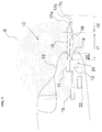
- Fig. 1 1 shows a schematic representation of a direct-reception Doppler LIDAR device 10.
- the direct-reception Doppler-LIDAR device 10 is installed in the illustrated example in an aircraft, illustrated by the example of an aircraft 13, as a carrier.
- Direct-receive Doppler LIDAR device 10 has a relatively narrow bandwidth laser source 11 (single-frequency operation, typically several kHz to MHz linewidth).
- the light of the laser source 11 - emitted laser beam 15 - is sent through a window 14 into the atmosphere 16.
- the light of the laser source 11 is elastically scattered on particles 17a, 17b, 17c,... Of the air in the case exemplified here.
- the scattered light 18 is picked up by a detector arrangement 12.
- the relative velocity is determined from the Doppler shift of the scattered light 18 backscattered relative to the direct-receiving Doppler LIDAR device 10 at the scattering particles 17a, 17b, 17c.
- a switching device 24, for example in front of the detector, is provided for switching between an active state in which light can be detected and an inactive state in which light can not be detected.
- a control device 22 is provided, by means of which the switching device 24 can be controlled by the laser source 11 depending on the emission of a laser pulse.
- the window 20 is an optical transmissive element for the radiation used for covering the direct-reception Doppler LIDAR device 10 against environmental influences (cover element) and is located at a certain distance 20 from the laser source 11 and the detector arrangement 12.
- the scattering of the particles 17a, 17b and 17c a distinction in this context, on the one hand, the scattering of molecules of the air (Rayleigh scattering) and the scattering of aerosols (dust particles, salt particles, etc., Mie scattering).
- the Rayleigh scattering can be reliably measured in all atmospheric layers and independently of meteorological influences; it only depends on the particle density, which continuously decreases to higher altitudes.
- the dispersion of aerosols is highly dependent on their local density, which can vary greatly depending on the weather conditions and other influences.
- aerosol scattering is very strong in high pollutant emission areas, such as in industrial areas or volcanic areas.
- aerosol scattering is quite low in the range of large bodies of water, for example over the oceans or in the area of the southern hemisphere of the earth.
- the aerosols are also washed out by, for example, heavy rain, so that their concentration can then be very low.
- the intensity of Rayleigh scattering is proportional to the reciprocal of the wavelength to the fourth power, it is useful to use a laser source 11 at the shortest possible wavelength, that is, for example, in the UV range.
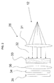
- FIG Fig. 2 An example of the detector array 12 of the direct-receive Doppler LIDAR device 10 is shown in FIG Fig. 2 shown in more detail.
- the scattered radiation - scattered light 18 - is passed through an optical system 26 to a detector 35 and detected.
- a frequency shift In principle, two measuring methods are conceivable for measuring a frequency shift.
- the so-called coherent detection the fixed phase relationship between the emitted laser beam of sufficiently narrow line width and the received scattered radiation is utilized. Due to the coherence, this measuring method is very sensitive.
- To measure the frequency shift a portion of the laser beam is redirected to the atmosphere prior to emission, mixed in a time-delayed manner and collinearly with the received scattered radiation on a photodetector of sufficiently large bandwidth. Due to the non-linearity of the photodetector, the difference frequency can be tapped directly as an electrical signal, which corresponds directly to the Doppler shift and therefore the relative velocity is proportional.
- Prerequisite for this measurement method is a sufficiently narrow-band laser source, so that the coherence length of the light is greater than the path difference between delayed reference radiation and received scattered radiation. Furthermore, the scattered radiation itself must not contribute to any significant line broadening, since otherwise the coherence would be destroyed. Typical limit values for the maximum line width and broadening in the case of scattering lie in the range of a few MHz.
- the in Fig. 2 illustrated so-called direct reception technique used, which does not require the phase of the radiation and makes only an intensity measurement.
- another element - for example a Fabry-Perot interferometer, etalon, other interferometer, etc. 33 - is provided which has frequency discrimination or wavelength dispersion.
- the received radiation 32 is supplied to the detector arrangement 12 for this purpose.
- the received radiation 32 is supplied via a first optics - collimation optics 31 - a so-called Fabry-Perot etalon 33, which has two plane-parallel, partially reflecting plates or a single plane-parallel plate with partial reflection on both surfaces, which by self-superposition of the wave in a resonator leads to an interference of the wave with itself.
- a spatial intensity distribution by imaging by means of a second optical system 36 on the detector 35, a spatial intensity distribution.
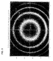
- a circular interference figure is produced by multiple reflection - so-called rings or English.
- Maxima and minima correspond to superimpositions of the same angle.
- a change in the radius of this interference pattern of Fig. 3 is directly proportional to the change in the wavelengths or frequency change of the detected signal and thus the change in the Dopplershift and thus the change in the relative velocity of the scattering particles, so for example, the scattering particles 17a, 17b, 17c of the air (Molecules, aerosols) to the measuring system.
- the relative velocity of the air with respect to the aircraft 13 can also be determined.
- the absolute relative speed in contrast to the previously described change in the relative speed
- the two- or even three-dimensional relative velocity vector can be determined. Accordingly, the principles and solutions proposed herein for one or more measurement directions may be applied.
- the detector arrangement 12 can be constructed differently.
- Various solutions include the use of filters at the edges of the interference maxima with downstream photodetectors, the interference pattern modeled concentric ring electrodes of a photomultiplier, the transformation of the circular pattern into a linear by means of fiber optics and detection with a CCD line detector or the detection with a two-dimensional photo Detector (for example CCD camera).
- CCD line detector for example CCD camera
- two-dimensional photo Detector for example CCD camera
- the direct-reception Doppler-LIDAR device 10 as well as a measurement method that can be performed therewith will be described using the example of the use of a CCD camera as detector 35 (see FIG Fig. 2 ) with an upstream microchannel plate 34 for Reinforcement further described.
- the microchannel plate 34 is also used as a switch in some embodiments.
- the light transit time n * r / c, ie refractive index n times distance r by vacuum speed of light c In the described case of a so-called monostatic system, in which transmitter - here: laser source 11 - and receiver - here: detector assembly 12 - are in a similar position and backscatter is used for LIDAR measurement, the light transit time is twice this, ie 2 xnxr / c. It can therefore be calculated very accurately, after which time the emission of a light pulse is received again from a defined distance.
- the detector 35 is switched on prematurely in advance ("exposure").
- exposure By means of, for example, the microchannel plate 34 functioning as a switch, however, the entire detector arrangement 12 is normally deactivated as a rule and only after a first time duration T1 after emitting a laser pulse 40 (FIG. Fig.
- Fig. 1 For the sake of simplicity, a beam propagation direction or measuring direction parallel to the direction of flight is sketched.
- the first time duration T1 and a second time duration T2 within which the detector arrangement is actively switched are divided by cos ⁇ by the distance r calculate the aircraft. If r1, r2 does not denote the distance in front of the aircraft, but the distance between LIDAR and measuring volume, this division is omitted.
- a CCD camera is used as detector 35, which has a typical exposure time of 16 ms at a frame rate of 60 frames per second, this image is actually exposed only with a fraction of this time.
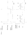
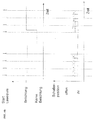
- Fig. 4a . 4b shown in the above illustration, the exposure times for the CCD camera are shown and below the time periods T1, T2 and times t1, t2 ( Fig. 4a ) for the switching device. Exposure is thus performed exactly so that only the light scattered at the desired distance is detected, see Fig. 4a . 4b , In addition, only during this short time backlight shines. In this way, however, only a comparatively small part of the background radiation is detected, while background light would be recorded during the entire exposure time of 16 ms with the detector array 12 constantly open
- Fig. 4b shows the case of detecting multiple laser pulses (four in this example) during a single (camera or detector) exposure time. According to the number of laser pulses to be recorded, the switching with the durations T1 and T2 is carried out correspondingly often. This clearly shows the advantage that by switching off the detector arrangement after the second time period T2 is recorded with a duration T1 + x until the detection of the next laser pulse corresponding to less background light (in the periods nz * T1 + x) and the signal quality is significantly improved thereby, while several pulses are integrated into a single overall measurement (exposure time).
- switching time ⁇ for activating and / or deactivating the detector arrangement 12 is as low as possible.
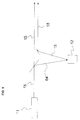
- These switching times ⁇ (flanks) are in Fig. 9 shown in more detail.
- this switching time ⁇ should be much less than 1 millisecond, preferably in the range of nanoseconds or microseconds. This can be achieved, for example, by means of a correspondingly fast switching element of the switching device 24, for example a switch connected upstream of the detector 35, or by, for example, electrical switching at the output of the detector 35.
- An exemplary arrangement of the switching device 24 is shown in FIG Fig. 5 shown in more detail, to which reference is made in the following.
- Fig. 5 shows the laser source 11 with the transmission beam - emitted laser beam 15 - and a decoupling device 50 for decoupling a portion of the laser beam 15 to a photodetector 52:
- the photodetector is connected via an input interface 51 to a counter 53.
- the counter 53 which is part of the control device 22 for activating / deactivating the detector arrangement 12, and a switching element of the switching device 24, here in the form of a switch 58, which is in the path of the scattered light 18 to be detected directed to the detector 35 is arranged.
- the switch 58 could be formed by the microchannel plate 34 or by another switch.
- the triggering of the switching on and off takes place by means of a suitable clock or the counter 53 or other suitable means, which in turn have an input for detecting the emitted laser pulse 40.
- the counter 53 has an input interface 51 with the photodetector 52, the a small fraction of the emitted laser beam 15 receives.
- the decoupling device 50 is provided with a slanted window 55 through which the fraction is decoupled.
- the coupling-out device can use stray light at the exit window or at a coupling-out mirror of the laser source 11, etc.
- a correspondingly processed electrical output signal is supplied to the counter 53, so that the first time period T1 can be referred to this time of the transmission of the laser pulse 40.
- the counter 53 supplies a switching signal 57 to the switch 58 at its input 62.
- the switch 58 is arranged in the receiving beam - scattered light 18 - and leaves this depending on the switching state to the detector 35 through or not.
- Typical detectors 35 are, as mentioned above, cameras, for example CCD cameras or comparable, ie also, for example, CMOS cameras, as well as so-called intensified cameras formed from detector and switchable microchannel plate. Further possible detector principles include 2D photodetector arrays, line arrays of photodetectors, photomultipliers with concentrically arranged ring electrodes or other 1- or 2D arrays of photodetectors or single detectors.
- switching device 24 in a corresponding manner also suitable switch is similar to the switching unit 60 constructed, but connected to the detector 35 and capable of short circuiting the detector 35 and its output accordingly (for example before the exposure).
- switchable microchannel plates 34 are also shown, which enable correspondingly fast switching over a larger area (as required for a CCD chip).
- Such rapidly switchable microchannel plates 34 can be switched either by controlling the acceleration voltage, or preferably by driving a gate electrode, usually a net-shaped electrode on the photocathode, or by both at the same time, typically in the range of nanoseconds.
- the second time duration T2 corresponding to a minimum measurement volume r2-r1, which requires the light to pass through the measurement volume and possibly back, can now be dependent on system parameters such as airspeed of an aircraft 13 in which the direct-reception Doppler LIDAR device 10 is mounted , or other parameters influencing the required measuring distance are set, wherein the Time T1 and T2 or time t1, t2 either fixed or dynamically controlled during a longer measuring insert can be controlled (for example T1 shorter at lower airspeeds and longer at higher airspeeds, so that the time between measurement and "flying through" the measuring volume constant is).
- the second time duration T2 corresponding to a minimum measurement volume r2-r1, which requires the light to pass through the measurement volume and possibly back can likewise be set as a function of measurement parameters such as the required intensity of the detected signal (eg T2 smaller with low backscatter intensity) Compensation due to larger backscatter volume, or T1 smaller with low backscatter intensity and thus also compensation due to smaller measuring distance).
- measurement parameters such as the required intensity of the detected signal (eg T2 smaller with low backscatter intensity) Compensation due to larger backscatter volume, or T1 smaller with low backscatter intensity and thus also compensation due to smaller measuring distance).
- Another possibility consists in the second time duration T2 corresponding to a minimum measurement volume r2-r1 which requires the light to pass through the measurement volume and optionally back, depending on system parameters such as the expected dynamics of the measurement signal, coherence or gradient of a measured or adapt to measuring air bubble etc.
- the setting of the time can now be controlled or regulated dynamically during a longer lasting measuring insert, or fixed, depending on the requirement of the measurement and the integration into the overall system.
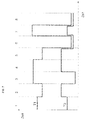
- Fig. 7 shows a longer measurement sequence with several individual measurements in sections 1 to 8.
- a large measurement range for safety / comfort increase may be set, as in Sections 3 and 4 in FIG Fig. 7 is shown.
- the first time period T1 is set large, so that only distances r1 are detected at a relatively large distance. Stray light from all closer sections reaches the detector 35 before the set switch-on time t1 and is therefore not detected.
- a short measuring distance is set with increased accuracy for the reduction of the wing area. This is done by setting the first time period T1 to a shorter value.
- a very short range for the optical measurement of air data is set by a corresponding selection of a small first time T1.
- the measurement depth can also be adapted to these requirements. For example, a large measurement depth at a great distance, ie set at T2, as in section 4 of Fig. 7 specified, or a small measurement depth at a short distance, as specified in section 1, set.
- Section 3 shows an exemplary setting of the second time period T2 at a great distance but with strong backscatter, for example in clouds.
- Section 1 describes the normal measurement conditions in relation to this.
- Another possibility is to set the first time T1 in Fig. 4b to shorten within one exposure from laser pulse to laser pulse in such a way that, despite the proper movement of the aircraft 13 in the air-related outer coordinate system, the measurement volume remains constant for each recorded laser pulse remains. Otherwise, the measurement volume would shift from laser pulse to laser pulse in accordance with the aircraft movement.
- the detector array 12 by activating and deactivating the detector array 12 such that the first time duration T1 is greater than the time that the light for the distance - distance 20 - in Fig. 1 from the laser source to the window 14 and back to the detector 35, a possible reflection on that window 14 or on a (dirt) layer thereon is not detected by the detector 35.
- This is particularly advantageous since scattered light at the exit window can be considerably more intense than the useful signal to be detected due to surface scattering or contamination and thus extremely disturbing proper detection of the useful signal depending on the circumstances.
- precisely this can be suppressed by the direct reception Doppler LIDAR device 10 described here and the measuring method described here.
- the measurement of the temporal change of the interference signal alone would not be sufficient.
- the change of the interference signal with respect to a reference point for example, known speed or speed equal to zero.
- One way of using the direct-reception Doppler-LIDAR device 10 shown here is essentially to couple a portion of the emitted laser light - laser beam 15 - directly (i.e., without emission into the atmosphere) into the detector assembly 12. Since this part of the laser light experiences no scattering on particles moved relative to the system - particles 17a, 17b, 17c - here the Doppler shift is 0. The signal can thus be used as the zero-point reference signal.
- Fig. 8 an embodiment of the direct-receive Doppler-LIDAR device 10 is illustrated, in which this signal is now obtained so that Part - laser signal 64 - of the laser source 11 emitted signal - laser beam 15 - is passed to the detector assembly 12 and the first time period T1 is now relative to the measurement in the air relatively short so chosen that this laser signal 64 is registered on the detector 35 , If the laser signal 64 is to be measured as a reference signal, the time periods T1 and T2 can now be selected so that T1 + T2 is smaller than the time until the laser light - scattered light 18 - is received from the atmosphere. By selecting T1 and T2 it is possible to select whether the reference signal or the atmospheric signal is detected.
- the reference signal can also be delayed, for example by means of a fiber coil, such that the signal backscattered by the atmosphere is suppressed by the selection of a correspondingly adapted first time duration T1, which is weak only from a very large measuring distance and thus only extremely (negligibly) , the time-delayed reference signal but just optimally detected.
- the above-described solution can be used for measuring several measuring directions for each of these directions, or only for individual ones, so that one reference signal is used as a reference for the other measuring directions.
- This measurement of the reference signal can now take place periodically or randomly over the entire measuring cycle of the LIDAR measurement, correspondingly changing the switching times of the detector 35 periodically or randomly.
Landscapes
- Physics & Mathematics (AREA)
- Engineering & Computer Science (AREA)
- Electromagnetism (AREA)
- Computer Networks & Wireless Communication (AREA)
- General Physics & Mathematics (AREA)
- Radar, Positioning & Navigation (AREA)
- Remote Sensing (AREA)
- Optical Radar Systems And Details Thereof (AREA)
Claims (15)
- Procédé pour la mesure de vitesse au LIDAR, dans lequel on oriente un faisceau laser (15) vers le milieu à mesurer (16) et on mesure au moyen d'un détecteur (35) le rayonnement (18) réémis ensuite par le milieu (16), et dans lequel on établit une zone de mesure dans l'espace (r1, r2) par activation du détecteur (35) après une première durée temporelle (T1) prédéterminée ou régulée de moins d'environ 500 µs après émission d'une impulsion laser (40) vers le milieu à mesurer (16) et par inactivation du détecteur (35) après une seconde durée temporelle (T2), incluant les étapes suivantes :a) on émet une impulsion laser (40) alors que le détecteur est inactif (35),b) on active le détecteur (35) à un instant de mise en marche (t1) prédéterminée ou régulée après émission de l'impulsion laser (40) de telle façon qu'une impulsion de rayonnement (18) diffusé par le milieu (16) après réception de l'impulsion laser (40) peut être reçue, etc) on inactive le détecteur (35) à un instant de mise à l'arrêt (t2) prédéterminé ou régulé, l'étape c) étant exécutée après l'étape (b),et incluant en outre :on établit l'instant de mise en marche (t1) prédéterminé ou régulé en correspondance d'un éloignement de mesure minimum souhaité (r1) de la source laser (11), eton établit la seconde durée temporelle prédéterminée ou régulée (T2) entre l'instant de mise en marche (t1) et l'instant de mise à l'arrêt (t2) en correspondance d'une profondeur de mesure souhaitée (r2-r1), ladite seconde durée temporelle (T2) étant inférieure à environ 1 µs,caractérisé par le fait queon met en marche détecteur au commencement d'un temps d'éclairage et on active le détecteur et on le désactive au moyen d'un dispositif de commutation pendant ce temps d'éclairage, la commutation étant effectuée plusieurs fois avec la première et avec la seconde durée temporelle, afin de détecter plusieurs impulsions laser pendant un unique temps d'éclairage,dans lequel les durées temporelles (T1, T2) et/ou les instants (t1, t2) sont régulé(e)s en fonction des paramètres suivants :- intensité minimum du signal détecté, et- intensité maximum du signal détecté.
- Procédé selon la revendication 1,
caractérisé en ce qu'un temps de commutation (t) est plus court qu'environ 1 µs dans la plage des nanosecondes. - Procédé selon l'une des revendications précédentes,
caractérisé en ce que
on établit ou on régule les durées temporelles (T1, T2) et/ou les instants (t1, t2) en fonction de paramètres de mesure et/ou de paramètres du système. - Procédé selon la revendication 3,
caractérisé en ce que les durées temporelles (T1, T2) et/ou les instants (tl, t2) sont établis ou régulés en fonction de l'un au moins des paramètres suivants :- intensité de consigne du signal détecté,- vitesse de déplacement d'un dispositif LIDAR au moyen duquel le procédé de mesure est mis en oeuvre,- dynamique attendue du signal de mesure,- cohérence et/ou gradient d'un écoulement mesuré dans le milieu (16), en particulier d'une rafale de vent lors de la mesure de vitesse de l'air. - Procédé selon l'une des revendications 3 ou 4,
caractérisé en ce que l'une au moins des durées temporelles (T1, T2) et/ou l'un au moins des instants (t1, T2) est commandé(e) et/ou régulé(e) au automatiquement de façon dynamique pendant une campagne de mesures de durée plus longue. - Procédé selon l'une des revendications précédentes,
caractérisé en ce que l'une au moins des durées temporelles (T1, T2) et/ou l'un au moins des instants (T1, T2) est sélectionné(e), commandé(e), régulé(e) et/ou établi(e) de façon différente afin de modifier la plage de mesure dans l'espace (r2-r1) pour des tâches de mesure différentes. - Procédé selon l'une des revendications précédentes,
caractérisé en ce que, pour un système de mesure en mouvement, la première durée temporelle (T1 est modifiée en fonction de la vitesse du système de mesure d'une impulsion de mesure à une autre impulsion de mesure à l'intérieur d'un processus d'éclairage. - Procédé selon l'une des revendications précédentes,
caractérisé en ce que le procédé est mis en oeuvre pour la mesure de vitesse de l'air depuis un aéronef, et le procédé est mis en oeuvre avec une grande distance de mesure pour la sécurité et pour l'amélioration du confort, il est mis en oeuvre avec une distance de mesure moyenne et avec haute précision afin de réduire la charge sur des composants de l'aéronef, et il est mis en oeuvre avec une courte distance de mesure pour la mesure optique de données aérauliques, et ladite au moins une période temporelle (T1, T2) et/ou l'un au moins des instants (t1, t2) est établi(e) en correspondance de ces tâches de mesure. - Procédé selon l'une des revendications précédentes,
caractérisé en ce qu'une partie du faisceau laser (15) est amenée au détecteur (35) sous forme de signal laser (64) pour fournir un signal de référence, et par modification des durées temporelles (T1, T2) on sélectionne une détection du signal de référence et/ou une détection du rayonnement (18) réémis par le milieu. - Procédé selon la revendication 9,
caractérisé en ce qu'une détection du signal de référence a lieu périodiquement ou de façon aléatoire dans un cycle de mesure respectif de la mesure LIDAR. - Procédé selon l'une des revendications 9 ou 10,
caractérisé en ce que le signal de référence est amené, avant d'atteindre le détecteur (35), sur un trajet de retard optique, afin de retarder le signal de référence. - Appareil LIDAR (10) pour mesurer des vitesses, comprenant une source laser (11) pour émettre un rayonnement laser (15) vers un milieu à mesurer (16) et un détecteur (35) pour la détection du rayonnement (18) qui, lors de l'application de rayonnement laser (15), est réémis par le milieu (16) est en particulier diffusé,
dans lequel la source laser (11) est capable d'émettre une impulsion laser (40),
il est prévu un dispositif de commutation (24) pour activer/désactiver le détecteur (35) en fonction d'un instant d'émission de l'impulsion laser (40) par la source laser (11), et
dans lequel le dispositif de commutation (24) est réalisé pour activer le détecteur (35) après une première durée temporelle prédéterminée ou régulée (T1) de moins d'environ 500 µs après émission de l'impulsion laser (40) vers le milieu à mesurer (16), et pour désactiver le détecteur (35) après une seconde durée temporelle (T2),
dans lequel il est prévu un dispositif de commande (22) au moyen duquel la première durée temporelle (T1) entre l'émission de l'impulsion laser provenant de la source laser (11) et l'instant de mise en marche (t1) pour le détecteur (35) et la seconde durée temporelle (T2) entre l'instant de mise en marche (t1) et l'instant de mise à l'arrêt (t2) pour le détecteur (35) sont susceptibles d'être commandées de telle façon qu'il est possible d'établir ainsi une distance de mesure (r1) et une profondeur de mesure (r1-r2), la seconde durée temporelle (T2) entre l'instant de mise en marche (t1) et l'instant de mise à l'arrêt (t2) étant plus courte qu'environ 1 µs,
caractérisé en ce que
le dispositif de commande (22) est réalisé pour mettre en marche le détecteur (35) au commencement d'un temps d'éclairage, et activer et désactiver le détecteur au moyen du dispositif de commande (24) pendant ce temps d'éclairage, de sorte que la commutation avec la première et la seconde durée temporelle est effectuée plusieurs fois afin de détecter plusieurs impulsions laser pendant un unique temps d'éclairage, et de réguler les durées temporelles (T1, T2) et/ou les instants (t1, t2) en fonction des paramètres suivants :- intensité minimum du signal détecté, et- intensité maximum du signal détecté. - Appareil LIDAR selon la revendication 12,
caractérisé en ce que le détecteur (35) comprend l'un au moins des dispositifs de détection de lumière suivants :- un détecteur d'imagerie, en particulier une caméra (36),- un élément photosensible, en particulier une photodiode ou un photomultiplicateur, ou- un groupe d'éléments photosensibles, en particulier de photodiodes,eta) en ce que le dispositif de commutation (24) comprend au moins un élément de commutation (58, 60, 34) placé en avant du détecteur (35) pour laisser passer ou pour bloquer un passage de lumière et/ou un guide de lumière vers le détecteur (35), qui est sélectionné parmi un groupe incluant :- une plaque à microcanaux commutable (34),- un commutateur electrooptique avec un matériau électrooptique,- une cellule à cristaux liquides, et/ou- un élément de commutation micromécanique déplaçable pour la commutation, et/oub) en ce que le dispositif de commutation (24) est relié à au moins une sortie du détecteur (35) afin d'effectuer la commutation pour l'activation/désactivation de façon électrique à la sortie du détecteur (35). - Appareil LIDAR selon l'une des revendications 12 ou 13, caractérisé en ce qu'il est prévu un élément de recouvrement optiquement transparent, en particulier une fenêtre (14), entre la source laser (11) et le détecteur (35) d'une part et entre le milieu à mesurer (16) d'autre part,
dans lequel les instants (tl, t2) pour activer/désactiver le détecteur (35) sont établis de telle façon que le détecteur (35) est inactif pendant un temps pendant lequel une impulsion laser (40) émise par la source laser (11), qui est réfléchie et/ou diffusée sur l'élément de recouvrement (14) optiquement transparent, parvient au détecteur (35). - Appareil LIDAR selon l'une des revendications précédentes, caractérisé en ce qu'il est agencé sur un support mobile, et les instants et/ou les durées temporelles pour activer/désactiver le détecteur sont commandé(e)s en fonction de la vitesse du support.
Applications Claiming Priority (2)
| Application Number | Priority Date | Filing Date | Title |
|---|---|---|---|
| DE102008031681A DE102008031681A1 (de) | 2008-07-04 | 2008-07-04 | LIDAR-Verfahren zur Messung von Geschwindigkeiten und LIDAR-Vorrichtung mit zeitgesteuerter Detektion |
| PCT/EP2009/058213 WO2010000751A1 (fr) | 2008-07-04 | 2009-06-30 | Procédé de mesure de vitesses par lidar et dispositif lidar à détection régulée dans le temps |
Publications (2)
| Publication Number | Publication Date |
|---|---|
| EP2297594A1 EP2297594A1 (fr) | 2011-03-23 |
| EP2297594B1 true EP2297594B1 (fr) | 2016-09-07 |
Family
ID=41213153
Family Applications (1)
| Application Number | Title | Priority Date | Filing Date |
|---|---|---|---|
| EP09772451.2A Not-in-force EP2297594B1 (fr) | 2008-07-04 | 2009-06-30 | Procédé de mesure de vitesses par lidar et dispositif lidar à détection régulée dans le temps |
Country Status (4)
| Country | Link |
|---|---|
| US (1) | US9383447B2 (fr) |
| EP (1) | EP2297594B1 (fr) |
| DE (1) | DE102008031681A1 (fr) |
| WO (1) | WO2010000751A1 (fr) |
Cited By (1)
| Publication number | Priority date | Publication date | Assignee | Title |
|---|---|---|---|---|
| US20230071312A1 (en) * | 2021-09-08 | 2023-03-09 | PassiveLogic, Inc. | External Activation of Quiescent Device |
Families Citing this family (89)
| Publication number | Priority date | Publication date | Assignee | Title |
|---|---|---|---|---|
| WO2014084973A1 (fr) * | 2012-11-30 | 2014-06-05 | HAYES, Paul, Byron | Système de mesure atmosphérique |
| US11609336B1 (en) | 2018-08-21 | 2023-03-21 | Innovusion, Inc. | Refraction compensation for use in LiDAR systems |
| RU2434247C1 (ru) * | 2010-05-11 | 2011-11-20 | Учреждение Российской академии наук Институт автоматики и электрометрии Сибирского отделения РАН | Способ формирования интерференционного сигнала в доплеровских лидарах |
| US8666570B1 (en) * | 2010-11-19 | 2014-03-04 | The Boeing Company | Volcanic ash detection by optical backscatter using standard aircraft lights |
| EP2994772B1 (fr) | 2013-05-06 | 2020-06-24 | Danmarks Tekniske Universitet | Système lidar à détection directe coaxiale |
| FR3005746B1 (fr) * | 2013-05-14 | 2016-09-16 | Cie Ind Des Lasers - Cilas | Dispositif d'illumination laser a obturateur integre. |
| US10983198B2 (en) * | 2015-06-24 | 2021-04-20 | Konica Minolta, Inc. | Objective sensor, objective sensor dirt determination method, and object detection device |
| DE102016200653A1 (de) | 2016-01-20 | 2017-07-20 | Robert Bosch Gmbh | Scheinwerfermodul, Scheinwerfer, Scheinwerfersystem und Betriebsverfahren für ein Scheinwerfermodul |
| US11556000B1 (en) | 2019-08-22 | 2023-01-17 | Red Creamery Llc | Distally-actuated scanning mirror |
| US12399278B1 (en) | 2016-02-15 | 2025-08-26 | Red Creamery Llc | Hybrid LIDAR with optically enhanced scanned laser |
| US12399279B1 (en) | 2016-02-15 | 2025-08-26 | Red Creamery Llc | Enhanced hybrid LIDAR with high-speed scanning |
| US12123950B2 (en) | 2016-02-15 | 2024-10-22 | Red Creamery, LLC | Hybrid LADAR with co-planar scanning and imaging field-of-view |
| US10444367B2 (en) * | 2016-02-26 | 2019-10-15 | Honeywell International Inc. | Enhanced LiDAR air data using supplementary sensor outputs |
| US20170276790A1 (en) * | 2016-03-22 | 2017-09-28 | Honeywell International Inc. | Hybrid air data systems using lidar and legacy air data sensors |
| US10451740B2 (en) * | 2016-04-26 | 2019-10-22 | Cepton Technologies, Inc. | Scanning lidar systems for three-dimensional sensing |
| US20180341009A1 (en) | 2016-06-23 | 2018-11-29 | Apple Inc. | Multi-range time of flight sensing |
| DE102016223892A1 (de) | 2016-12-01 | 2018-06-07 | Zf Friedrichshafen Ag | LiDAR mit preselektiertem Erfassungsbereich |
| KR102580275B1 (ko) * | 2016-12-30 | 2023-09-18 | 이노뷰전, 인크. | 다중파장 라이다 설계 |
| US10942257B2 (en) | 2016-12-31 | 2021-03-09 | Innovusion Ireland Limited | 2D scanning high precision LiDAR using combination of rotating concave mirror and beam steering devices |
| CN110573900A (zh) | 2017-01-05 | 2019-12-13 | 图达通爱尔兰有限公司 | 用于编码和译码LiDAR的方法和系统 |
| US11054508B2 (en) | 2017-01-05 | 2021-07-06 | Innovusion Ireland Limited | High resolution LiDAR using high frequency pulse firing |
| US11009605B2 (en) | 2017-01-05 | 2021-05-18 | Innovusion Ireland Limited | MEMS beam steering and fisheye receiving lens for LiDAR system |
| US10838067B2 (en) | 2017-01-17 | 2020-11-17 | Aptiv Technologies Limited | Object detection system |
| WO2018191630A1 (fr) * | 2017-04-14 | 2018-10-18 | Arizona Board Of Regents On Behalf Of The University Of Arizona | Systèmes et procédés de guidage de faisceau à l'aide d'un dispositif à micromiroirs |
| WO2018191696A1 (fr) | 2017-04-14 | 2018-10-18 | Arizona Board Of Regents On Behalf Of The University Of Arizona | Procédés et appareil utilisant une modulation angulaire et spatiale de lumière |
| WO2018191694A1 (fr) | 2017-04-14 | 2018-10-18 | Arizona Board Of Regents On Behalf Of The University Of Arizona | Procédés et appareil de modulation angulaire et spatiale de lumière |
| DE102017111117A1 (de) * | 2017-05-22 | 2018-11-22 | Deutsches Zentrum für Luft- und Raumfahrt e.V. | Verfahren zur Ermittlung der Luftgeschwindigkeit eines Flugzeugs |
| WO2019005260A1 (fr) | 2017-06-29 | 2019-01-03 | Apple Inc. | Cartographie de profondeur de temps de vol à compensation de parallaxe |
| US20200132841A1 (en) * | 2017-06-30 | 2020-04-30 | A^3 By Airbus Llc | Systems and methods for controlling aircraft based on sensed air movement |
| US10754033B2 (en) | 2017-06-30 | 2020-08-25 | Waymo Llc | Light detection and ranging (LIDAR) device range aliasing resilience by multiple hypotheses |
| DE102017115710A1 (de) | 2017-07-12 | 2019-02-07 | Airbus Defence and Space GmbH | LIDAR-Anordnung und LIDAR-Verfahren |
| US10627492B2 (en) * | 2017-08-01 | 2020-04-21 | Waymo Llc | Use of extended detection periods for range aliasing detection and mitigation in a light detection and ranging (LIDAR) system |
| US10955552B2 (en) | 2017-09-27 | 2021-03-23 | Apple Inc. | Waveform design for a LiDAR system with closely-spaced pulses |
| WO2019079642A1 (fr) | 2017-10-19 | 2019-04-25 | Innovusion Ireland Limited | Lidar à plage dynamique étendue |
| WO2019125349A1 (fr) | 2017-12-18 | 2019-06-27 | Montrose Laboratories Llc | Détection de temps de vol à l'aide d'un réseau adressable d'émetteurs |
| US11503255B2 (en) | 2017-12-22 | 2022-11-15 | Arizona Board Of Regents On Behalf Of The University Of Arizona | Methods and apparatus for angular and spatial modulation of light |
| US11493601B2 (en) | 2017-12-22 | 2022-11-08 | Innovusion, Inc. | High density LIDAR scanning |
| US10948599B2 (en) | 2018-01-03 | 2021-03-16 | Goodrich Corporation | Phasing light pulses with detectors |
| WO2019139895A1 (fr) | 2018-01-09 | 2019-07-18 | Innovusion Ireland Limited | Systèmes et procédés de détection lidar utilisant des miroirs multi-plans |
| US11675050B2 (en) | 2018-01-09 | 2023-06-13 | Innovusion, Inc. | LiDAR detection systems and methods |
| US11927696B2 (en) | 2018-02-21 | 2024-03-12 | Innovusion, Inc. | LiDAR systems with fiber optic coupling |
| WO2019165130A1 (fr) | 2018-02-21 | 2019-08-29 | Innovusion Ireland Limited | Systèmes et procédés de détection lidar avec une fréquence de récurrence élevée pour observer des objets éloignés |
| US12298399B2 (en) | 2018-02-22 | 2025-05-13 | Seyond, Inc. | Receive path for LiDAR system |
| WO2019165294A1 (fr) | 2018-02-23 | 2019-08-29 | Innovusion Ireland Limited | Système de direction bidimensionnelle de systèmes lidar |
| WO2020013890A2 (fr) | 2018-02-23 | 2020-01-16 | Innovusion Ireland Limited | Orientation d'impulsions à longueurs d'onde multiples dans des systèmes lidar |
| US11422234B2 (en) | 2018-02-23 | 2022-08-23 | Innovusion, Inc. | Distributed lidar systems |
| US11567182B2 (en) | 2018-03-09 | 2023-01-31 | Innovusion, Inc. | LiDAR safety systems and methods |
| US10439713B1 (en) * | 2018-03-15 | 2019-10-08 | The Boeing Company | System and method for receiving signal information for networking using a free space optical link |
| US11789132B2 (en) | 2018-04-09 | 2023-10-17 | Innovusion, Inc. | Compensation circuitry for lidar receiver systems and method of use thereof |
| CN114114295B (zh) | 2018-06-15 | 2025-06-06 | 图达通智能美国有限公司 | 用于聚焦感兴趣的范围的lidar系统和方法 |
| US11860316B1 (en) | 2018-08-21 | 2024-01-02 | Innovusion, Inc. | Systems and method for debris and water obfuscation compensation for use in LiDAR systems |
| US11579300B1 (en) | 2018-08-21 | 2023-02-14 | Innovusion, Inc. | Dual lens receive path for LiDAR system |
| US11796645B1 (en) | 2018-08-24 | 2023-10-24 | Innovusion, Inc. | Systems and methods for tuning filters for use in lidar systems |
| US11614526B1 (en) | 2018-08-24 | 2023-03-28 | Innovusion, Inc. | Virtual windows for LIDAR safety systems and methods |
| US12625240B2 (en) | 2018-08-24 | 2026-05-12 | Seyond, Inc. | Systems and methods for tuning filters for use in LiDAR systems |
| US11579258B1 (en) | 2018-08-30 | 2023-02-14 | Innovusion, Inc. | Solid state pulse steering in lidar systems |
| US12313788B1 (en) | 2018-10-09 | 2025-05-27 | Seyond, Inc. | Ultrashort pulses in LiDAR systems |
| US11686824B2 (en) | 2018-11-14 | 2023-06-27 | Innovusion, Inc. | LiDAR systems that use a multi-facet mirror |
| CN113302515B (zh) * | 2019-01-10 | 2024-09-24 | 图达通智能美国有限公司 | 具有光束转向和广角信号检测的lidar系统和方法 |
| WO2020167338A1 (fr) | 2019-02-11 | 2020-08-20 | Apple Inc. | Détection de profondeur à l'aide d'un réseau épars de faisceaux pulsés |
| US11977185B1 (en) | 2019-04-04 | 2024-05-07 | Seyond, Inc. | Variable angle polygon for use with a LiDAR system |
| US11500094B2 (en) | 2019-06-10 | 2022-11-15 | Apple Inc. | Selection of pulse repetition intervals for sensing time of flight |
| US11828771B2 (en) | 2019-07-15 | 2023-11-28 | The Boeing Company | Method and system for collecting air data using a laser-induced plasma channel |
| US11555900B1 (en) | 2019-07-17 | 2023-01-17 | Apple Inc. | LiDAR system with enhanced area coverage |
| US11733359B2 (en) * | 2019-12-03 | 2023-08-22 | Apple Inc. | Configurable array of single-photon detectors |
| US11774594B2 (en) | 2020-06-23 | 2023-10-03 | Honeywell International Inc. | Air data system with optical modulator on receive channels for stroboscopic detection |
| DE102020211101A1 (de) | 2020-09-03 | 2022-03-03 | Robert Bosch Gesellschaft mit beschränkter Haftung | Optischer Umgebungssensor sowie Fahrzeug |
| US11754484B2 (en) * | 2020-09-22 | 2023-09-12 | Honeywell International Inc. | Optical air data system fusion with remote atmospheric sensing |
| US12442926B2 (en) | 2021-02-04 | 2025-10-14 | Apple Inc. | Time-of-flight depth sensing with improved linearity |
| US12061289B2 (en) | 2021-02-16 | 2024-08-13 | Innovusion, Inc. | Attaching a glass mirror to a rotating metal motor frame |
| US11422267B1 (en) | 2021-02-18 | 2022-08-23 | Innovusion, Inc. | Dual shaft axial flux motor for optical scanners |
| US11789128B2 (en) | 2021-03-01 | 2023-10-17 | Innovusion, Inc. | Fiber-based transmitter and receiver channels of light detection and ranging systems |
| US12196860B2 (en) | 2021-03-02 | 2025-01-14 | Apple Inc. | Depth sensor calibration using internal reflections |
| US11555895B2 (en) | 2021-04-20 | 2023-01-17 | Innovusion, Inc. | Dynamic compensation to polygon and motor tolerance using galvo control profile |
| US11614521B2 (en) | 2021-04-21 | 2023-03-28 | Innovusion, Inc. | LiDAR scanner with pivot prism and mirror |
| WO2022225859A1 (fr) | 2021-04-22 | 2022-10-27 | Innovusion, Inc. | Conception lidar compacte à haute résolution et à champ de vision ultra-large |
| EP4305450A1 (fr) | 2021-04-22 | 2024-01-17 | Innovusion, Inc. | Conception lidar compacte à haute résolution et à champ de vision ultra-large |
| US11520023B2 (en) | 2021-05-10 | 2022-12-06 | Optowaves, Inc. | High-speed time-of-interference light detection and ranging apparatus |
| US11294040B1 (en) | 2021-05-10 | 2022-04-05 | Optowaves, Inc. | Time-of-interference light detection and ranging apparatus |
| EP4314885A1 (fr) | 2021-05-12 | 2024-02-07 | Innovusion, Inc. | Systèmes et appareils d'atténuation de bruit, de vibrations et de dureté de lidars |
| US11662440B2 (en) | 2021-05-21 | 2023-05-30 | Innovusion, Inc. | Movement profiles for smart scanning using galvonometer mirror inside LiDAR scanner |
| US11768294B2 (en) | 2021-07-09 | 2023-09-26 | Innovusion, Inc. | Compact lidar systems for vehicle contour fitting |
| US11681028B2 (en) | 2021-07-18 | 2023-06-20 | Apple Inc. | Close-range measurement of time of flight using parallax shift |
| US12468017B2 (en) | 2021-10-15 | 2025-11-11 | Seyond, Inc. | Integrated mirror motor galvanometer |
| CN216356147U (zh) | 2021-11-24 | 2022-04-19 | 图达通智能科技(苏州)有限公司 | 一种车载激光雷达电机、车载激光雷达及车辆 |
| US11871130B2 (en) | 2022-03-25 | 2024-01-09 | Innovusion, Inc. | Compact perception device |
| US12204033B2 (en) | 2022-03-25 | 2025-01-21 | Seyond, Inc. | Multimodal detection with integrated sensors |
| US11892566B1 (en) | 2022-09-22 | 2024-02-06 | Optowaves, Inc. | Multiplexed light detection and ranging apparatus |
| US20240168164A1 (en) * | 2022-11-21 | 2024-05-23 | The Boeing Company | Optical dual wavelength laser speed detection system |
Family Cites Families (13)
| Publication number | Priority date | Publication date | Assignee | Title |
|---|---|---|---|---|
| US6384903B1 (en) * | 1977-02-28 | 2002-05-07 | Bae Systems Information And Electronic Systems Integration, Inc. | Range gated remote measurement utilizing two-photon absorption |
| US4195931A (en) * | 1978-05-18 | 1980-04-01 | The United States Of America As Represented By The Secretary Of The Army | Clear air turbulence detector |
| DE4013702C2 (de) | 1990-04-28 | 1996-01-11 | Christian Dipl Phys Heupts | Verfahren zur Erfassung von Turbulenzen in der Atmosphäre sowie Einrichtung zur Durchführung des Verfahrens |
| US5394238A (en) * | 1992-11-09 | 1995-02-28 | Honeywell Inc. | Look-ahead windshear detector by filtered Rayleigh and/or aerosol scattered light |
| US7495774B2 (en) * | 2002-03-01 | 2009-02-24 | Michigan Aerospace Corporation | Optical air data system |
| US6894768B2 (en) * | 2002-08-02 | 2005-05-17 | Ophir Corporation | Optical air data systems and methods |
| GB0304344D0 (en) * | 2003-02-26 | 2003-04-02 | Bae Systems Plc | Gas velocity sensor |
| DE10316762B4 (de) * | 2003-04-10 | 2007-01-25 | Eads Deutschland Gmbh | Verfahren zur Erfassung von Windgeschwindigkeiten mit einem Doppler-Lidar-System, insbesondere an Bord von Flugzeugen, und Doppler-Lidar-System |
| FR2870942B1 (fr) | 2004-05-25 | 2006-08-25 | Airbus France Sas | Systeme de mesure anticipee d'une turbulence en amont d'un aeronef |
| DE102005034729B3 (de) * | 2005-07-21 | 2007-02-08 | Eads Deutschland Gmbh | Verfahren und Lidar-System zur Messung von Luftturbulenzen an Bord von Luftfahrzeugen sowie für Flughäfen und Windfarmen |
| US7554652B1 (en) * | 2008-02-29 | 2009-06-30 | Institut National D'optique | Light-integrating rangefinding device and method |
| CN102439393B (zh) * | 2009-05-15 | 2014-08-20 | 密歇根宇航公司 | 范围成像激光雷达 |
| US8730472B2 (en) * | 2011-07-22 | 2014-05-20 | Exxonmobil Research And Engineering Company | Method for predicting haze in lubricant base stocks |
-
2008
- 2008-07-04 DE DE102008031681A patent/DE102008031681A1/de not_active Withdrawn
-
2009
- 2009-06-30 EP EP09772451.2A patent/EP2297594B1/fr not_active Not-in-force
- 2009-06-30 WO PCT/EP2009/058213 patent/WO2010000751A1/fr not_active Ceased
- 2009-06-30 US US13/002,479 patent/US9383447B2/en not_active Expired - Fee Related
Cited By (2)
| Publication number | Priority date | Publication date | Assignee | Title |
|---|---|---|---|---|
| US20230071312A1 (en) * | 2021-09-08 | 2023-03-09 | PassiveLogic, Inc. | External Activation of Quiescent Device |
| US12250099B2 (en) * | 2021-09-08 | 2025-03-11 | PassiveLogic, Inc. | External activation of quiescent device |
Also Published As
| Publication number | Publication date |
|---|---|
| WO2010000751A1 (fr) | 2010-01-07 |
| DE102008031681A1 (de) | 2010-01-14 |
| US9383447B2 (en) | 2016-07-05 |
| US20110181864A1 (en) | 2011-07-28 |
| EP2297594A1 (fr) | 2011-03-23 |
Similar Documents
| Publication | Publication Date | Title |
|---|---|---|
| EP2297594A1 (fr) | Procédé de mesure de vitesses par lidar et dispositif lidar à détection régulée dans le temps | |
| EP2300852B1 (fr) | Dispositif lidar doppler à réception directe et procédé associé | |
| EP3809157B1 (fr) | Capteur optoélectronique de mesure de distance et procédé de détection d'un objet cible | |
| EP1613980B1 (fr) | Procede pour detecter des vitesses de vent au moyen d'un systeme doppler-lidar, notamment a bord d'avions, et systeme doppler-lidar | |
| EP2476013B1 (fr) | Détecteur de photons comportant un élément immobilisable sensible aux photons, notamment une photodiode à avalanche spad, et télémètre doté d'un détecteur de photons de ce type | |
| EP1901093B1 (fr) | Réception d'images distantes | |
| EP2558883B1 (fr) | Appareil de mesure de distance à évaluation de mesure à effet homogénéisant | |
| DE69635858T2 (de) | Telezentrische 3d kamera und zugehöriges verfahren | |
| EP1910868A1 (fr) | Procede et systeme lidar pour mesurer des turbulences d'air a bord d'aeronefs ainsi que pour les aeroports et les parcs d'eoliennes | |
| EP2486370A1 (fr) | Télémètre optique avec dispositif d'étalonnage | |
| EP4083660A1 (fr) | Dispositif lidar doppler destiné à la détection des situations de vent et/ou de turbulences | |
| US6813020B2 (en) | Device for determining the values of at least one parameter of particles, especially of water droplets | |
| DE10130763A1 (de) | Vorrichtung zur optischen Distanzmessung über einen grossen Messbereich | |
| DE102005015914A1 (de) | Kombinierte Laser-Höhen- und Bodengeschwindigkeits-Messvorrichtung | |
| DE102018220932A1 (de) | Verfahren zum Bestimmen des Abstands und Rückstrahlvermögens einer Objektoberfläche | |
| DE112015000377T5 (de) | Optischer Sensor | |
| EP3193195B1 (fr) | Capteur optique | |
| EP3519858B1 (fr) | Unité de balayage d'un dispositif de réception et d'émission optique d'un dispositif de détection optique d'un véhicule | |
| WO2010025846A1 (fr) | Dispositif et procédé de mesure de vitesse | |
| DE29923959U1 (de) | Online-Partikelgrößenmeßgerät | |
| DE2607169A1 (de) | Verfahren und messanordnung zur bestimmung des konzentrationsprofils von luftverunreinigungen oder natuerlichen bestandteilen in der atmosphaere | |
| DE102024117875A1 (de) | Lidar-Sensorsystem für ein Fahrzeug, Lokalisieren eines Objekts sowie Bestimmen eines Fahrbahnzustands | |
| US11550033B2 (en) | Electro-optical beam deflecting unit for light detection and ranging (LiDAR) | |
| DE3316600A1 (de) | Augensicheres schraegsichtmessgeraet | |
| EP4639073A1 (fr) | Système et procédé de mesure interférométrique de distance |
Legal Events
| Date | Code | Title | Description |
|---|---|---|---|
| PUAI | Public reference made under article 153(3) epc to a published international application that has entered the european phase |
Free format text: ORIGINAL CODE: 0009012 |
|
| 17P | Request for examination filed |
Effective date: 20110126 |
|
| AK | Designated contracting states |
Kind code of ref document: A1 Designated state(s): AT BE BG CH CY CZ DE DK EE ES FI FR GB GR HR HU IE IS IT LI LT LU LV MC MK MT NL NO PL PT RO SE SI SK TR |
|
| AX | Request for extension of the european patent |
Extension state: AL BA RS |
|
| DAX | Request for extension of the european patent (deleted) | ||
| 17Q | First examination report despatched |
Effective date: 20130430 |
|
| RAP1 | Party data changed (applicant data changed or rights of an application transferred) |
Owner name: AIRBUS DEFENCE AND SPACE GMBH |
|
| REG | Reference to a national code |
Ref country code: DE Ref legal event code: R079 Ref document number: 502009013063 Country of ref document: DE Free format text: PREVIOUS MAIN CLASS: G01S0017950000 Ipc: G01S0017580000 |
|
| GRAP | Despatch of communication of intention to grant a patent |
Free format text: ORIGINAL CODE: EPIDOSNIGR1 |
|
| RIC1 | Information provided on ipc code assigned before grant |
Ipc: G01S 17/58 20060101AFI20160413BHEP Ipc: G01S 17/95 20060101ALI20160413BHEP |
|
| INTG | Intention to grant announced |
Effective date: 20160429 |
|
| GRAS | Grant fee paid |
Free format text: ORIGINAL CODE: EPIDOSNIGR3 |
|
| GRAA | (expected) grant |
Free format text: ORIGINAL CODE: 0009210 |
|
| AK | Designated contracting states |
Kind code of ref document: B1 Designated state(s): AT BE BG CH CY CZ DE DK EE ES FI FR GB GR HR HU IE IS IT LI LT LU LV MC MK MT NL NO PL PT RO SE SI SK TR |
|
| REG | Reference to a national code |
Ref country code: GB Ref legal event code: FG4D Free format text: NOT ENGLISH |
|
| REG | Reference to a national code |
Ref country code: CH Ref legal event code: EP |
|
| REG | Reference to a national code |
Ref country code: IE Ref legal event code: FG4D Free format text: LANGUAGE OF EP DOCUMENT: GERMAN |
|
| REG | Reference to a national code |
Ref country code: DE Ref legal event code: R096 Ref document number: 502009013063 Country of ref document: DE |
|
| REG | Reference to a national code |
Ref country code: AT Ref legal event code: REF Ref document number: 827343 Country of ref document: AT Kind code of ref document: T Effective date: 20161015 |
|
| REG | Reference to a national code |
Ref country code: LT Ref legal event code: MG4D |
|
| REG | Reference to a national code |
Ref country code: NL Ref legal event code: MP Effective date: 20160907 |
|
| PG25 | Lapsed in a contracting state [announced via postgrant information from national office to epo] |
Ref country code: HR Free format text: LAPSE BECAUSE OF FAILURE TO SUBMIT A TRANSLATION OF THE DESCRIPTION OR TO PAY THE FEE WITHIN THE PRESCRIBED TIME-LIMIT Effective date: 20160907 Ref country code: LT Free format text: LAPSE BECAUSE OF FAILURE TO SUBMIT A TRANSLATION OF THE DESCRIPTION OR TO PAY THE FEE WITHIN THE PRESCRIBED TIME-LIMIT Effective date: 20160907 Ref country code: NO Free format text: LAPSE BECAUSE OF FAILURE TO SUBMIT A TRANSLATION OF THE DESCRIPTION OR TO PAY THE FEE WITHIN THE PRESCRIBED TIME-LIMIT Effective date: 20161207 Ref country code: FI Free format text: LAPSE BECAUSE OF FAILURE TO SUBMIT A TRANSLATION OF THE DESCRIPTION OR TO PAY THE FEE WITHIN THE PRESCRIBED TIME-LIMIT Effective date: 20160907 |
|
| PG25 | Lapsed in a contracting state [announced via postgrant information from national office to epo] |
Ref country code: NL Free format text: LAPSE BECAUSE OF FAILURE TO SUBMIT A TRANSLATION OF THE DESCRIPTION OR TO PAY THE FEE WITHIN THE PRESCRIBED TIME-LIMIT Effective date: 20160907 Ref country code: ES Free format text: LAPSE BECAUSE OF FAILURE TO SUBMIT A TRANSLATION OF THE DESCRIPTION OR TO PAY THE FEE WITHIN THE PRESCRIBED TIME-LIMIT Effective date: 20160907 Ref country code: SE Free format text: LAPSE BECAUSE OF FAILURE TO SUBMIT A TRANSLATION OF THE DESCRIPTION OR TO PAY THE FEE WITHIN THE PRESCRIBED TIME-LIMIT Effective date: 20160907 Ref country code: LV Free format text: LAPSE BECAUSE OF FAILURE TO SUBMIT A TRANSLATION OF THE DESCRIPTION OR TO PAY THE FEE WITHIN THE PRESCRIBED TIME-LIMIT Effective date: 20160907 Ref country code: GR Free format text: LAPSE BECAUSE OF FAILURE TO SUBMIT A TRANSLATION OF THE DESCRIPTION OR TO PAY THE FEE WITHIN THE PRESCRIBED TIME-LIMIT Effective date: 20161208 |
|
| PG25 | Lapsed in a contracting state [announced via postgrant information from national office to epo] |
Ref country code: EE Free format text: LAPSE BECAUSE OF FAILURE TO SUBMIT A TRANSLATION OF THE DESCRIPTION OR TO PAY THE FEE WITHIN THE PRESCRIBED TIME-LIMIT Effective date: 20160907 Ref country code: RO Free format text: LAPSE BECAUSE OF FAILURE TO SUBMIT A TRANSLATION OF THE DESCRIPTION OR TO PAY THE FEE WITHIN THE PRESCRIBED TIME-LIMIT Effective date: 20160907 |
|
| PG25 | Lapsed in a contracting state [announced via postgrant information from national office to epo] |
Ref country code: PL Free format text: LAPSE BECAUSE OF FAILURE TO SUBMIT A TRANSLATION OF THE DESCRIPTION OR TO PAY THE FEE WITHIN THE PRESCRIBED TIME-LIMIT Effective date: 20160907 Ref country code: BG Free format text: LAPSE BECAUSE OF FAILURE TO SUBMIT A TRANSLATION OF THE DESCRIPTION OR TO PAY THE FEE WITHIN THE PRESCRIBED TIME-LIMIT Effective date: 20161207 Ref country code: SK Free format text: LAPSE BECAUSE OF FAILURE TO SUBMIT A TRANSLATION OF THE DESCRIPTION OR TO PAY THE FEE WITHIN THE PRESCRIBED TIME-LIMIT Effective date: 20160907 Ref country code: CZ Free format text: LAPSE BECAUSE OF FAILURE TO SUBMIT A TRANSLATION OF THE DESCRIPTION OR TO PAY THE FEE WITHIN THE PRESCRIBED TIME-LIMIT Effective date: 20160907 Ref country code: IS Free format text: LAPSE BECAUSE OF FAILURE TO SUBMIT A TRANSLATION OF THE DESCRIPTION OR TO PAY THE FEE WITHIN THE PRESCRIBED TIME-LIMIT Effective date: 20170107 Ref country code: PT Free format text: LAPSE BECAUSE OF FAILURE TO SUBMIT A TRANSLATION OF THE DESCRIPTION OR TO PAY THE FEE WITHIN THE PRESCRIBED TIME-LIMIT Effective date: 20170109 |
|
| REG | Reference to a national code |
Ref country code: DE Ref legal event code: R097 Ref document number: 502009013063 Country of ref document: DE |
|
| REG | Reference to a national code |
Ref country code: FR Ref legal event code: PLFP Year of fee payment: 9 |
|
| PG25 | Lapsed in a contracting state [announced via postgrant information from national office to epo] |
Ref country code: IT Free format text: LAPSE BECAUSE OF FAILURE TO SUBMIT A TRANSLATION OF THE DESCRIPTION OR TO PAY THE FEE WITHIN THE PRESCRIBED TIME-LIMIT Effective date: 20160907 |
|
| PLBE | No opposition filed within time limit |
Free format text: ORIGINAL CODE: 0009261 |
|
| STAA | Information on the status of an ep patent application or granted ep patent |
Free format text: STATUS: NO OPPOSITION FILED WITHIN TIME LIMIT |
|
| PG25 | Lapsed in a contracting state [announced via postgrant information from national office to epo] |
Ref country code: DK Free format text: LAPSE BECAUSE OF FAILURE TO SUBMIT A TRANSLATION OF THE DESCRIPTION OR TO PAY THE FEE WITHIN THE PRESCRIBED TIME-LIMIT Effective date: 20160907 |
|
| 26N | No opposition filed |
Effective date: 20170608 |
|
| PG25 | Lapsed in a contracting state [announced via postgrant information from national office to epo] |
Ref country code: SI Free format text: LAPSE BECAUSE OF FAILURE TO SUBMIT A TRANSLATION OF THE DESCRIPTION OR TO PAY THE FEE WITHIN THE PRESCRIBED TIME-LIMIT Effective date: 20160907 |
|
| PG25 | Lapsed in a contracting state [announced via postgrant information from national office to epo] |
Ref country code: MC Free format text: LAPSE BECAUSE OF FAILURE TO SUBMIT A TRANSLATION OF THE DESCRIPTION OR TO PAY THE FEE WITHIN THE PRESCRIBED TIME-LIMIT Effective date: 20160907 |
|
| REG | Reference to a national code |
Ref country code: CH Ref legal event code: PL |
|
| REG | Reference to a national code |
Ref country code: IE Ref legal event code: MM4A |
|
| REG | Reference to a national code |
Ref country code: DE Ref legal event code: R082 Ref document number: 502009013063 Country of ref document: DE Representative=s name: KASTEL PATENTANWAELTE, DE Ref country code: DE Ref legal event code: R082 Ref document number: 502009013063 Country of ref document: DE Ref country code: DE Ref legal event code: R082 Ref document number: 502009013063 Country of ref document: DE Representative=s name: KASTEL PATENTANWAELTE PARTG MBB, DE |
|
| PG25 | Lapsed in a contracting state [announced via postgrant information from national office to epo] |
Ref country code: LU Free format text: LAPSE BECAUSE OF NON-PAYMENT OF DUE FEES Effective date: 20170630 Ref country code: IE Free format text: LAPSE BECAUSE OF NON-PAYMENT OF DUE FEES Effective date: 20170630 Ref country code: CH Free format text: LAPSE BECAUSE OF NON-PAYMENT OF DUE FEES Effective date: 20170630 Ref country code: LI Free format text: LAPSE BECAUSE OF NON-PAYMENT OF DUE FEES Effective date: 20170630 |
|
| REG | Reference to a national code |
Ref country code: BE Ref legal event code: MM Effective date: 20170630 |
|
| REG | Reference to a national code |
Ref country code: DE Ref legal event code: R082 Ref document number: 502009013063 Country of ref document: DE Representative=s name: KASTEL PATENTANWAELTE PARTG MBB, DE |
|
| REG | Reference to a national code |
Ref country code: FR Ref legal event code: PLFP Year of fee payment: 10 |
|
| REG | Reference to a national code |
Ref country code: AT Ref legal event code: MM01 Ref document number: 827343 Country of ref document: AT Kind code of ref document: T Effective date: 20170630 |
|
| PG25 | Lapsed in a contracting state [announced via postgrant information from national office to epo] |
Ref country code: BE Free format text: LAPSE BECAUSE OF NON-PAYMENT OF DUE FEES Effective date: 20170630 |
|
| PG25 | Lapsed in a contracting state [announced via postgrant information from national office to epo] |
Ref country code: MT Free format text: LAPSE BECAUSE OF FAILURE TO SUBMIT A TRANSLATION OF THE DESCRIPTION OR TO PAY THE FEE WITHIN THE PRESCRIBED TIME-LIMIT Effective date: 20160907 |
|
| PG25 | Lapsed in a contracting state [announced via postgrant information from national office to epo] |
Ref country code: AT Free format text: LAPSE BECAUSE OF NON-PAYMENT OF DUE FEES Effective date: 20170630 |
|
| PG25 | Lapsed in a contracting state [announced via postgrant information from national office to epo] |
Ref country code: HU Free format text: LAPSE BECAUSE OF FAILURE TO SUBMIT A TRANSLATION OF THE DESCRIPTION OR TO PAY THE FEE WITHIN THE PRESCRIBED TIME-LIMIT; INVALID AB INITIO Effective date: 20090630 |
|
| PG25 | Lapsed in a contracting state [announced via postgrant information from national office to epo] |
Ref country code: CY Free format text: LAPSE BECAUSE OF NON-PAYMENT OF DUE FEES Effective date: 20160907 |
|
| PG25 | Lapsed in a contracting state [announced via postgrant information from national office to epo] |
Ref country code: MK Free format text: LAPSE BECAUSE OF FAILURE TO SUBMIT A TRANSLATION OF THE DESCRIPTION OR TO PAY THE FEE WITHIN THE PRESCRIBED TIME-LIMIT Effective date: 20160907 |
|
| PG25 | Lapsed in a contracting state [announced via postgrant information from national office to epo] |
Ref country code: TR Free format text: LAPSE BECAUSE OF FAILURE TO SUBMIT A TRANSLATION OF THE DESCRIPTION OR TO PAY THE FEE WITHIN THE PRESCRIBED TIME-LIMIT Effective date: 20160907 |
|
| PGFP | Annual fee paid to national office [announced via postgrant information from national office to epo] |
Ref country code: GB Payment date: 20220622 Year of fee payment: 14 |
|
| PGFP | Annual fee paid to national office [announced via postgrant information from national office to epo] |
Ref country code: FR Payment date: 20220628 Year of fee payment: 14 |
|
| PGFP | Annual fee paid to national office [announced via postgrant information from national office to epo] |
Ref country code: DE Payment date: 20230620 Year of fee payment: 15 |
|
| GBPC | Gb: european patent ceased through non-payment of renewal fee |
Effective date: 20230630 |
|
| PG25 | Lapsed in a contracting state [announced via postgrant information from national office to epo] |
Ref country code: GB Free format text: LAPSE BECAUSE OF NON-PAYMENT OF DUE FEES Effective date: 20230630 |
|
| PG25 | Lapsed in a contracting state [announced via postgrant information from national office to epo] |
Ref country code: FR Free format text: LAPSE BECAUSE OF NON-PAYMENT OF DUE FEES Effective date: 20230630 |
|
| REG | Reference to a national code |
Ref country code: DE Ref legal event code: R119 Ref document number: 502009013063 Country of ref document: DE |
|
| PG25 | Lapsed in a contracting state [announced via postgrant information from national office to epo] |
Ref country code: DE Free format text: LAPSE BECAUSE OF NON-PAYMENT OF DUE FEES Effective date: 20250101 |