EP2296969B1 - Luftfahrzeugleitungsüberwachungssystem und -verfahren - Google Patents
Luftfahrzeugleitungsüberwachungssystem und -verfahren Download PDFInfo
- Publication number
- EP2296969B1 EP2296969B1 EP09765613A EP09765613A EP2296969B1 EP 2296969 B1 EP2296969 B1 EP 2296969B1 EP 09765613 A EP09765613 A EP 09765613A EP 09765613 A EP09765613 A EP 09765613A EP 2296969 B1 EP2296969 B1 EP 2296969B1
- Authority
- EP
- European Patent Office
- Prior art keywords
- mass flow
- flow rate
- gas mass
- pressure
- normal mode
- Prior art date
- Legal status (The legal status is an assumption and is not a legal conclusion. Google has not performed a legal analysis and makes no representation as to the accuracy of the status listed.)
- Active
Links
Images


Classifications
-
- B—PERFORMING OPERATIONS; TRANSPORTING
- B64—AIRCRAFT; AVIATION; COSMONAUTICS
- B64D—EQUIPMENT FOR FITTING IN OR TO AIRCRAFT; FLIGHT SUITS; PARACHUTES; ARRANGEMENT OR MOUNTING OF POWER PLANTS OR PROPULSION TRANSMISSIONS IN AIRCRAFT
- B64D15/00—De-icing or preventing icing on exterior surfaces of aircraft
- B64D15/02—De-icing or preventing icing on exterior surfaces of aircraft by ducted hot gas or liquid
-
- B—PERFORMING OPERATIONS; TRANSPORTING
- B64—AIRCRAFT; AVIATION; COSMONAUTICS
- B64D—EQUIPMENT FOR FITTING IN OR TO AIRCRAFT; FLIGHT SUITS; PARACHUTES; ARRANGEMENT OR MOUNTING OF POWER PLANTS OR PROPULSION TRANSMISSIONS IN AIRCRAFT
- B64D13/00—Arrangements or adaptations of air-treatment apparatus for aircraft crew or passengers, or freight space
-
- G—PHYSICS
- G01—MEASURING; TESTING
- G01M—TESTING STATIC OR DYNAMIC BALANCE OF MACHINES OR STRUCTURES; TESTING OF STRUCTURES OR APPARATUS, NOT OTHERWISE PROVIDED FOR
- G01M3/00—Investigating fluid-tightness of structures
- G01M3/02—Investigating fluid-tightness of structures by using fluid or vacuum
- G01M3/26—Investigating fluid-tightness of structures by using fluid or vacuum by measuring rate of loss or gain of fluid, e.g. by pressure-responsive devices, by flow detectors
- G01M3/28—Investigating fluid-tightness of structures by using fluid or vacuum by measuring rate of loss or gain of fluid, e.g. by pressure-responsive devices, by flow detectors for pipes, cables or tubes; for pipe joints or seals; for valves ; for welds
- G01M3/2807—Investigating fluid-tightness of structures by using fluid or vacuum by measuring rate of loss or gain of fluid, e.g. by pressure-responsive devices, by flow detectors for pipes, cables or tubes; for pipe joints or seals; for valves ; for welds for pipes
- G01M3/2815—Investigating fluid-tightness of structures by using fluid or vacuum by measuring rate of loss or gain of fluid, e.g. by pressure-responsive devices, by flow detectors for pipes, cables or tubes; for pipe joints or seals; for valves ; for welds for pipes using pressure measurements
-
- Y—GENERAL TAGGING OF NEW TECHNOLOGICAL DEVELOPMENTS; GENERAL TAGGING OF CROSS-SECTIONAL TECHNOLOGIES SPANNING OVER SEVERAL SECTIONS OF THE IPC; TECHNICAL SUBJECTS COVERED BY FORMER USPC CROSS-REFERENCE ART COLLECTIONS [XRACs] AND DIGESTS
- Y02—TECHNOLOGIES OR APPLICATIONS FOR MITIGATION OR ADAPTATION AGAINST CLIMATE CHANGE
- Y02T—CLIMATE CHANGE MITIGATION TECHNOLOGIES RELATED TO TRANSPORTATION
- Y02T50/00—Aeronautics or air transport
- Y02T50/40—Weight reduction
Definitions
- the invention relates to an aircraft line monitoring system and method, in particular for an aircraft wing deicing system and an aircraft air conditioning system.
- An essential state of the art is through WO 2005/015326 given.
- Aircraft have a de-icing system that directs hot bleed air from an engine to a wing during flight, particularly the wing leading edges.
- the wing is kept at a temperature that ensures that no ice forms on the wing.
- ice on a wing can lead to a crash of the aircraft.
- the use of this de-icing system is particularly important when descending. If the aircraft flies at high altitude, for example 10,000 meters, the air is relatively low in humidity, but it is very cold. As a result, the wing of the aircraft is cooled to a low temperature. During descent, the aircraft may enter humid air layers.
- the wing of the aircraft is still at a temperature well below 0 ° C, when descending below a height of about 7,300 meters (about 22,000 feet) ice may form on the wing, which can lead to a crash.
- the hot air directed to the leading edge of the wing has the task of warming the wing of the aircraft so that no ice can form on the wing during the descent.
- a leaking hot air duct in a wing may result in the wing not being completely de-iced. Furthermore, hot air enters the wing interior, which can damage components in the wing and affect the structural integrity of the wing.
- Hot air having a temperature of about 200 ° C and higher can reduce the strength of a prior art wing made of a metal. It is planned to construct the wings of future aircraft generations from a composite material in order to reduce their weight.
- a composite material used is glass fiber reinforced plastic (GRP), whose structural integrity is already decreasing at about 85 ° C. It must therefore be prevented that engine bleed air with a temperature of about 200 ° C enters a made of a composite material wing. In a wing made of a composite material, the occurrence may occur hot air into the wing will have a stronger impact on the structural integrity of the wing.
- GRP glass fiber reinforced plastic
- a pressure sensor that detects the static pressure in the pipe and a flow sensor that detects the air flow are provided in the pipe.
- a temperature sensor may be provided which detects the temperature of the air flowing through the conduit. If the temperature and the air volume flow are known, the air mass flow can be determined from this.
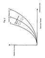
- the FIG. 1 shows a first characteristic 101 of the air mass flow over the static pressure in the line, if no leakage exists.
- the characteristic 102 shows the static pressure over the air mass flow, if there is a leak.
- the leakage results in a new characteristic of air mass flow to static pressure. It can set a lower static pressure at constant air mass flow or a higher air mass flow at constant static pressure. However, it is also possible that both variables change.
- the air volume flow can be measured and the air mass flow can be calculated with the help of the air temperature.
- the characteristic curve between air mass flow and static pressure is subject to fluctuations due to specimen scattering of the duct system in the amount of about ⁇ 5% and more.
- mounting tolerances for bends and branches can affect the characteristics of air mass flow and static pressure. If no tolerance is used, the system has the in FIG. 2 If the maximum error in a first direction is taken as the basis, the system has the characteristic 104 and if the maximum error is based on a second, opposite direction, the system has the characteristic 105. If a point or a characteristic moves inside of the limited by the characteristics 104 and 105 area, leakage can not be detected.
- FIG. 3 shows the characteristic 103, in which no tolerance is used.
- the characteristic curve 104 shows the case in which a maximum tolerance in a first direction is used
- the characteristic curve 105 shows the case in which a maximum tolerance in a second, opposite direction is used. If a point of the characteristic curve 103 moves between the area bounded by the characteristic lines 104 and 105, leakage is not detectable.
- the characteristic curve 102 shows a line with a leakage. Since the characteristic 102 is outside the range bounded by the characteristics 104 and 105, this leakage can be detected. The leakage must therefore have a relatively large extent so that it can be detected. In the in the FIG.
- the working point 106 of the system is on the characteristic 104, since all components of the system have the maximum tolerance in the first direction.
- the ratio of mass air flow to static pressure shifts to point 107. It can be seen that the static pressure must change by a large amount so that the leakage can be detected. Under certain circumstances, this leads to the fact that a small leakage can not be recognized, but which nevertheless can lead to the structural problems mentioned at the beginning in the case of blades made of a composite material but also in the case of a wing of the prior art made of metal.
- the case is shown in which all components of the system have a maximum tolerance in the second, opposite direction.
- the operating point 108 of the system is in the normal operation on the characteristic 105.
- the operating point 107 is on the characteristic curve 102. Even with a small change in the static pressure from the value DP1 to the value DP2, the system detects a leak. Thus, it is possible that a small pressure change is interpreted as leakage.
- FIG. 5 shows the characteristic 103, the ratio of air mass flow to static pressure, if no tolerances are used.
- the characteristic 104 represents the case where all components of the system have a tolerance in the first direction
- the characteristic 105 represents the case where all components of the system have a tolerance in the second, opposite direction.
- the operating point 109 of the system lies on the characteristic 104. All components of the system therefore have a tolerance in the first direction.
- the operating point 107 on the characteristic curve 102 This is within the undetectable range between the characteristics 104 and 105, as previously described.
- the prior art system can not detect a relatively large change in static pressure. Therefore, there may be problems with the structural integrity of the wing, as hot air may enter the wing without being recognized by a prior art system.
- an aircraft line monitoring system having an airline-mountable conduit that directs gas from a source to a deployment site.
- a flow detection device is arranged, which detects a gas mass flow in the line.
- a pressure detection device detects a static pressure in the line.
- a control device is designed to detect at least one learning operation-actual gas mass flow in a learning operation and to store the learning operation-actual gas mass flow as desired gas mass flow for normal operation.
- the controller is further configured to detect a learning operation actual pressure and to store it as a target pressure for normal operation.
- a leak in the line to be monitored is excluded, so that the values of the learning mode actual gas mass flow and the learning mode actual pressure detected in the learning mode correspond to gas mass flow and pressure values in a line without a leak.
- the controller compares a normal operation-actual gas mass flow with the target gas mass flow and / or a normal operation-actual pressure with the set pressure.
- gas also includes a gas mixture, such as air, and any gaseous fluid.
- the location of use may be an air outlet on a wing or a nozzle in a passenger cabin.
- bends in the line, branches and other assembly tolerances affect the characteristics between air mass flow and static pressure.
- the sensitivity of the aircraft line monitoring system is not affected by these tolerances, since the influence of these tolerances is taken into account in the learning mode of the control device.
- the aircraft line monitoring system also has the advantage that static tolerances of the flow sensing device, the pressure sensing device, and the temperature sensor do not limit the sensitivity of the system.
- the aircraft line monitoring system described above is particularly suitable for applications in which only one operating point of air mass flow and static pressure is used in normal operation.
- the aircraft line monitoring system detects, in the learning mode, a plurality of learning operation actual gas mass flow values at different learning operation actual pressures, respectively.
- the controller allocates each learning operation actual gas mass flow to a learning operation actual pressure.
- Each learning operation actual gas mass flow is stored as a target gas mass flow and each learning operation actual pressure is stored as a target pressure for a normal operation.
- the control device also stores an association between the respective desired pressure and the respective desired volume flow.
- the control device receives a normal operation-actual gas mass flow value from the flow detection device and a normal operation-actual pressure value from the pressure detection device. It is compared to the normal operation-actual pressure associated target gas mass flow with the normal operation-actual gas mass flow.
- the control device If the normal operation actual gas mass flow deviates by more than a threshold value from the target gas mass flow, the control device outputs a signal indicating a deviation.
- the control device may alternatively or additionally receive a normal operation-actual gas mass flow from the flow detection device in normal operation and obtain a normal operation-actual pressure from the pressure detection device. The nominal pressure associated with the normal operation actual gas mass flow is compared with the normal operation actual pressure. If the normal operation actual pressure differs by more than a threshold value from the target pressure, the controller outputs a signal indicating a deviation. It is understood that the controller may output a signal indicative of a deviation and / or output a signal or value indicative of the magnitude of the deviation.
- this aircraft line monitoring system a plurality of points on the gas mass flow to static pressure characteristic line are received in the line.
- This system is suitable for an application in which the values of the gas mass flow and / or the static pressure in operation depending on Operating mode can be varied. Any number of points can be recorded on the characteristic curve. Further, the controller may interpolate between the recorded points. This interpolation can be done during the learning mode or during normal operation. Apart from numerical inaccuracies, the interpolation maintains the relationship between the set pressure and the set flow rate, depending on the interpolation method used.
- the flow sensing device may include a venturi nozzle and provide a difference between a pressure prevailing upstream of the venturi nozzle and a pressure prevailing downstream of the venturi nozzle as a measure of the gas flow rate.
- the flow rate detection device may also be a so-called hot wire anomometer.
- a hot-wire anomometer has a temperature-dependent electrical resistance, which is electrically heated.
- the electrical conductor is cooled as a function of the flow rate.
- the temperature of the electrical resistance can be determined by means of a resistance measurement, which makes it possible to deduce the flow velocity.
- a temperature sensor may be provided in the line or in the flow rate detection device.
- the gas volume flow corresponds to the quotient of the gas mass flow and the density of the gas or gas mixture.
- the density of the gas or gas mixture depends on the temperature.
- a gas mass flow value can be exchanged for a gas volume flow value.
- the flow detection device can detect a gas volume flow and the control device can process a gas volume flow value instead of a gas mass flow value. It is also conceivable that the flow rate detection device detects a gas volume flow and the control device calculates a gas mass flow value by means of a temperature value. The flow detection device can detect the gas volume flow and determine and output the gas mass flow by means of a detected temperature.
- An aircraft wing de-icing system comprises the aircraft line monitoring system described above.
- the location where the conduit of the aircraft line monitoring system directs the gas flowing through the conduit comprises at least one gas outlet in an aircraft wing.
- the aircraft wing may be an airfoil of a conventional aircraft or a wing moving in the form of a rotor blade of a helicopter relative to the aircraft.
- An aircraft air conditioning system comprises the aircraft line monitoring system described above.
- the location where the line of the aircraft line monitoring system directs the gas flowing through the line is, for example, at least one nozzle which supplies air to the cabin.
- the invention also relates to a method of monitoring a mass flow of gas in an aircraft-mounted conduit from a gas source to a deployment site having a learning operation and a normal operation.
- a learning operation actual gas mass flow is determined, a learning operation actual pressure determined, and the learning operation actual gas mass flow as the target gas mass flow and the learning operation actual pressure as the target pressure.
- a normal operation-actual gas mass flow is determined, a normal operation-actual pressure determined, the normal operation-actual gas mass flow with the desired mass flow and / or the normal operation-actual pressure compared with the target pressure and outputs a warning signal, if the normal operation-actual gas mass flow deviates from the desired gas mass flow by more than a threshold value and / or the normal operation-actual pressure deviates from the target pressure by more than a threshold value.
- the method detects a plurality of learning mode actual gas mass flow values at respectively different learning operation actual pressures.
- Each learning mode actual gas mass flow is assigned to the respective learning mode actual pressure.
- Each learning operation-actual gas mass flow is stored as a target gas mass flow, each learning operation-actual pressure is stored as a target pressure and also an association between the respective target pressure and the respective target gas mass flow is stored.
- the method performs the detection of the normal operation gas mass flow and the detection of the normal operation actual pressure. Subsequently, the nominal gas mass flow associated with the normal operation actual pressure with the normal operation actual gas mass flow compared and / or compared to the normal operation-actual gas mass flow associated desired pressure with the normal operation-actual pressure. A warning signal is output if the normal operation-actual gas mass flow deviates from the respective desired gas mass flow or the normal operation-actual pressure deviates from the respective desired pressure by more than a threshold value.
- the method may interpolate between at least two desired pressure values and / or at least two desired gas mass flow values.
- the method can be controlled at least partially by the control device described above.
- the controller may be implemented by a computer having a memory. It is understood that the control device can also be formed by a plurality of separate devices that implement one or more steps of the method described above.
- the controller may include a memory device, a comparator, an output device, an interpolator, and the like.
- a gas volume flow value can be detected and processed.
- the physical relationships described above can be used.
- the method may be used to detect an air supply disruption during defrost of an aircraft wing.
- the location where the conduit of the aircraft line monitoring system directs the gas flowing through the conduit then comprises at least one gas outlet in the aircraft wing.
- the method may be used to monitor the air supply when air conditioning the aircraft cabin. In this method, for example, at least one air outlet nozzle in the cabin forms the location where the line of the aircraft line monitoring system directs the gas flowing through the line.
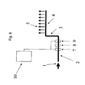
- FIG. 6 shows an air duct system comprising a first conduit 2, a second conduit 3 and a third conduit, which are arranged one behind the other.
- the airflow 1 may be hot engine bleed air.
- the third conduit 4 has openings 5 through which the air exits the conduit.
- the openings 5 may be transverse to the direction of the airflow and / or in the same direction as the airflow. It can also be provided only an opening.
- the openings 5 may be located, for example, in a wing of an aircraft to de-ice the wing.
- the air flow 1 is supplied by an air conditioner and the openings 5 are located in a cabin of an aircraft.
- the first line 2 there is a flow rate detection device 7, an optional temperature sensor 8 and a pressure detection device 9.
- the optional temperature sensor 8 is coupled to the flow rate detection device 7.
- the flow rate detection device 7 and the pressure detection device 9 are coupled to a control device 10. It is also possible that the optional temperature sensor 8 is not coupled to the flow rate detection device 7 but to the control device 10.
- the flow sensing device 7 may include a venturi and provide a pressure differential upstream and downstream of the venturi as a measure of the gas flow rate.
- the flow rate detection device 7 may also be a so-called hot wire anomometer.
- a hot-wire anomometer has a temperature-dependent electrical resistance, which is electrically heated.
- the electrical conductor is cooled as a function of the flow rate.
- the temperature of the electrical resistance can be determined by means of a resistance measurement, which makes it possible to deduce the flow velocity.
- the air volume flow is the quotient of the air mass flow and the density of air.
- the density of air depends on the temperature.
- the air mass flow can be calculated from a detected air volume flow and a temperature.
- the flow rate detection device 7 and the temperature sensor 8 provide an actual value of the air mass flow.
- the pressure detector 9 provides an actual value of the static pressure in the first conduit.
- a learning operation actual gas mass flow and a learning operation actual pressure are detected.
- the controller 10 stores the learning operation actual air mass flow as the target air mass flow and the learning operation actual pressure as the target pressure.
- the normal operation-actual air mass flow and the normal operation-actual pressure is determined.
- the normal operation-actual air mass flow is compared with the desired air mass flow and / or the normal operation-actual pressure is compared with the target pressure by the control device.
- a warning signal is issued if the normal operation-actual air mass flow deviates from the desired air mass flow by more than a threshold value or the normal operation-actual pressure deviates from the target pressure by more than a threshold value.
- This procedure is suitable if the air line system is operated only at a desired pressure or nominal air mass flow. This may be the case with a de-icing system for a wing of an aircraft.
- a plurality of learning mode actual air mass flow values may also be determined at respectively different learning operation actual pressures.
- Each learning mode actual air mass flow is assigned to the respective learning mode actual pressure.
- the controller 10 stores each learning operation actual air mass flow value as the target air mass flow value, each learning operation actual pressure value as the target pressure value, and an association between the respective target pressure and the respective target air mass flow.
- the assignment can be achieved by pairwise saving, by storing in a table, by pointers and the like.
- the in FIG. 7 generated by the reference numeral 12 system characteristic of the static pressure in dependence of the air mass flow.
- the system characteristic 12 takes into account influences of line bends, line branches, a cable diameter and their dispersion.
- This characteristic curve also records the static measurement errors of the measured values of receiving and processing components in the airline system.
- a region 16 in which a leak can not be detected comprises only the dynamic tolerances of the components receiving and processing measured values, for example their aging and their temperature dispersion. Depending on the design, it can also include the aging and temperature dispersion of the line components. Thus, the region 16 in which leakage can not be detected is much smaller than in a prior art system.
- interpolation can be made between the desired air mass flow values and / or desired pressure values.
- the interpolation may be performed during the learning operation or the normal operation.
- various techniques are known, for example a polynomial interpolation or a spillover interpolation and the like, so that these interpolation methods require no further explanation.
- the learning operation is required only once after the assembly of the aircraft or after replacement of piping components of the air duct system, the flow rate detecting device, the temperature sensor or the pressure detecting device.
- the learning operation can also be repeated during maintenance in order to take into account the aging phenomena of the measurement-receiving and processing components and to minimize the region 16 in which leakage can not be detected.
- the normal operation-actual air mass flow and the normal operation-actual pressure are detected.
- the nominal air mass flow associated with the normal operation actual pressure is compared with the normal operation actual air mass flow. Additionally or alternatively, the nominal pressure associated with the normal operation-actual air mass flow can be compared with the normal operation-actual pressure.
- a warning signal is output if the normal operation-actual air mass flow from the respective desired air mass flow or the normal operation-actual pressure deviates from the respective desired pressure by more than a threshold value.
- the control device assigns the static air pressure LM1 to the air mass flow LM1.
- the air mass flow LM1 is stored as the desired air mass flow and the static pressure DP1 is stored as the desired pressure. This point of the characteristic is identified by the reference numeral 18.
- the air mass flow LM1 and the static pressure DP2 are detected. This point is identified by the reference numeral 20.
- the air mass flow LM1 is associated with the desired pressure DP1.
- the normal operation actual pressure is DP2.
- the difference between DP1 and DP2 is greater than a predetermined threshold.
- the controller 10 indicates that there is leakage.
- the present invention has the advantage that in addition to a leakage and a partial or complete blockage of a pipe and / or nozzle or a change in the air source can be detected, since this changes the characteristic of the static pressure on the air mass flow. Furthermore, the present invention can take into account static measurement errors of the sensors used. The present invention may also consider influences by bends in the ducts, branch lines and the like. The area 16, in which a fault in the air duct system can not be detected, is considerably smaller in the aircraft line monitoring system according to the invention than in the prior art. The present invention provides a safer aircraft because de-icing of the wing can be better monitored.
- the entry of hot air into the wing and the concomitant danger of structural instability, particularly when using composite materials in the wing, can be detected more reliably than in the prior art. Further, a more comfortable Aircraft created because the function of the air conditioning can be better monitored.
Landscapes
- Engineering & Computer Science (AREA)
- Aviation & Aerospace Engineering (AREA)
- Physics & Mathematics (AREA)
- General Physics & Mathematics (AREA)
- Health & Medical Sciences (AREA)
- General Health & Medical Sciences (AREA)
- Pulmonology (AREA)
- Measuring Volume Flow (AREA)
- Pipeline Systems (AREA)
- Examining Or Testing Airtightness (AREA)
Description
- Die Erfindung betrifft ein Luftfahrzeugleitungsüberwachungssystem und -verfahren, insbesondere für ein Luftfahrzeugflügelenteisungssystem und eine Luftfahrzeugklimaanlage. Ein wesentlicher Stand der Technik ist durch
WO 2005/015326 gegeben. - Flugzeuge weisen ein Enteisungssystem auf, das während des Fluges heiße Zapfluft von einem Triebwerk zu einem Flügel, insbesondere den Flügelvorderkanten, leitet. Dadurch wird während des Fluges der Flügel bei einer Temperatur gehalten, bei der sicherstellt ist, dass sich kein Eis am Flügel bildet. Wie allgemein bekannt ist, kann Eis an einem Flügel zu einem Absturz des Flugzeuges führen. Der Einsatz dieses Enteisungssystems ist insbesondere beim Sinkflug wichtig. Fliegt das Flugzeug in großer Höhe, beispielsweise 10.000 Meter, weist die Luft relativ wenig Feuchtigkeit auf, jedoch ist sie sehr kalt. Dadurch wird auch der Flügel des Flugzeuges auf eine niedrige Temperatur abgekühlt. Während des Sinkfluges kann das Flugzeug in feuchtere Luftschichten eintreten. Da der Flügel des Luftfahrzeuges immer noch eine Temperatur deutlich unter 0°C aufweist, kann sich beim Sinkflug unterhalb einer Höhe von etwa 7.300 Metern (etwa 22.000 Fuß) Eis am Flügel bilden, was zu einem Absturz führen kann. Wie eingangs erwähnt, hat die zu den Flügelvorderkanten geleitete heiße Luft die Aufgabe, den Flügel des Flugzeuges so zu erwärmen, dass auch während des Sinkflugs kein Eis am Flügel entstehen kann.
- Eine undichte Heißluftleitung in einem Flügel kann dazu führen, dass der Flügel nicht vollständig enteist wird. Ferner tritt heiße Luft in das Flügelinnere ein, was Bauteile im Flügel beschädigen kann und die strukturelle Integrität des Flügels beeinträchtigen kann.
- Heiße Luft mit einer Temperatur von etwa 200°C und höher kann die Festigkeit eines aus einem Metall hergestellten Flügels des Standes der Technik reduzieren. Es ist geplant, die Flügel zukünftiger Flugzeuggenerationen aus einem Verbundmaterial aufzubauen, um deren Gewicht zu reduzieren. Ein verwendetes Verbundmaterial ist glasfaserverstärkter Kunststoff (GFK), dessen strukturelle Integrität bei bereits ca. 85°C abnimmt. Es muss folglich verhindert werden, dass Triebwerkszapfluft mit einer Temperatur von etwa 200°C in einen aus einem Verbundmaterial hergestellten Flügel eintritt. Bei einem aus einem Verbundmaterial hergestellten Flügel kann das Eintreten heißer Luft in den Flügel stärkere Auswirkungen auf die strukturelle Integrität des Flügels nach sich ziehen.
- Um sicherzustellen, dass die Flügel zuverlässig enteist werden, werden in der Leitung ein Drucksensor, der den statischen Druck in der Leitung erfasst, und ein Durchflusssensor vorgesehen, der den Luftvolumenstrom erfasst. Optional kann ein Temperatursensor vorgesehen sein, der die Temperatur der durch die Leitung strömenden Luft erfasst. Sind die Temperatur und der Luftvolumenstrom bekannt, kann daraus der Luftmassenstrom bestimmt werden.
- Die
Figur 1 zeigt eine erste Kennlinie 101 des Luftmassenstroms über den statischen Druck in der Leitung, falls keine Leckage vorliegt. Die Kennlinie 102 zeigt den statischen Druck über den Luftmassenstrom, falls eine Leckage vorhanden ist. Durch die Leckage ergibt sich eine neue Charakteristik von Luftmassenstrom zu statischem Druck. Es kann sich ein geringerer statischer Druck bei gleichbleibendem Luftmassenstrom oder ein höherer Luftmassenstrom bei gleichbleibendem statischen Druck einstellen. Es ist jedoch auch möglich, dass sich beide Größen ändern. Es kann der Luftvolumenstrom gemessen werden und mit Hilfe der Lufttemperatur der Luftmassenstrom berechnet werden. - Die Kennlinie zwischen Luftmassenstrom und statischem Druck unterliegt Schwankungen aufgrund von Exemplarstreuungen des Leitungssystems in der Höhe von etwa ± 5% und mehr. Beispielsweise können Montagetoleranzen bei Biegungen und Abzweigungen die Kennlinie von Luftmassenstrom und statischem Druck beeinflussen. Falls keine Toleranz zugrundegelegt wird, hat das System die in
Figur 2 gezeigte Kennlinie 103. Falls der maximale Fehler in eine erste Richtung zugrundegelegt wird, hat das System die Kennlinie 104 und falls der maximale Fehler in eine zweite, entgegengesetzte Richtung zugrundegelegt wird, hat das System die Kennlinie 105. Bewegt sich ein Punkt oder eine Kennlinie innerhalb des durch die Kennlinien 104 und 105 beschränkten Bereichs, kann eine Leckage nicht erkannt werden. -
Figur 3 zeigt die Kennlinie 103, bei der keine Toleranz zugrundegelegt wird. Die Kennlinie 104 zeigt den Fall, bei dem eine maximale Toleranz in eine erste Richtung zugrundegelegt wird, und die Kennlinie 105 zeigt den Fall, bei dem eine maximale Toleranz in eine zweite, entgegengesetzte Richtung zugrundegelegt wird. Bewegt sich ein Punkt von der Kennlinie 103 zwischen dem von den Kennlinien 104 und 105 beschränkten Bereich, so ist eine Leckage nicht detektierbar. Im Beispiel derFigur 3 zeigt die Kennlinie 102 eine Leitung mit einer Leckage. Da sich die Kennlinie 102 außerhalb des von den Kennlinien 104 und 105 begrenzten Bereichs befindet, kann diese Leckage detektiert werden. Die Leckage muss also ein relativ großes Ausmaß aufweisen, damit sie detektiert werden kann. In dem in derFigur 3 gezeigten Beispiel befindet sich der Arbeitspunkt 106 des Systems auf der Kennlinie 104, da alle Bauteile des Systems die maximale Toleranz in die erste Richtung aufweisen. Im Falle einer Leckage verschiebt sich das Verhältnis von Luftmassenstrom zu statischem Druck zum Punkt 107. Man erkennt, dass sich der statische Druck um einen hohen Wert ändern muss, damit die Leckage erkannt werden kann. Dies führt unter Umständen dazu, dass eine kleine Leckage nicht erkannt werden kann, die aber trotzdem zu den eingangs erwähnten Strukturproblemen bei Flügeln aus einem Verbundmaterial aber auch bei einem Flügel des Standes der Technik aus Metall führen kann. - In
Figur 4 ist der Fall dargestellt, bei dem alle Bauteile des Systems eine maximale Toleranz in die zweite, entgegengesetzte Richtung aufweisen. Somit befindet sich der Arbeitspunkt 108 des Systems im Normalbetrieb auf der Kennlinie 105. Im Fall einer Leckage befindet sich der Arbeitspunkt 107 auf der Kennlinie 102. Schon bei einer geringen Änderung des statischen Drucks vom Wert DP1 zum Wert DP2 detektiert das System eine Leckage. Somit ist es möglich, dass eine geringe Druckänderung als Leckage interpretiert wird. - In
Figur 5 zeigt die Kennlinie 103 das Verhältnis von Luftmassenstrom zu statischem Druck, falls keine Toleranzen zugrundegelegt werden. Die Kennlinie 104 stellt den Fall dar, bei dem alle Bauteile des Systems eine Toleranz in der ersten Richtung aufweisen, und die Kennlinie 105 stellt den Fall dar, bei dem alle Bauteile des Systems eine Toleranz in die zweite, entgegengesetzte Richtung aufweisen. Bei dem inFigur 5 dargestellten Fall liegt der Arbeitspunkt 109 des Systems auf der Kennlinie 104. Alle Bauteile des Systems weisen also eine Toleranz in die erste Richtung auf. Im Fall einer Leckage ergibt sich bei dem inFigur 5 dargestellten Fall der Arbeitspunkt 107 auf der Kennlinie 102. Dieser liegt innerhalb des nicht detektierbaren Bereichs zwischen den Kennlinien 104 und 105, wie zuvor beschrieben wurde. Somit kann das System des Standes der Technik eine relativ große Änderung des statischen Drucks nicht erkennen. Daher können sich Probleme mit der strukturellen Integrität des Flügels ergeben, da heiße Luft in den Flügel eintreten kann, ohne dass dies von einem System des Standes der Technik erkannt werden kann. - Die zuvor geschilderten Probleme können umgangen werden, indem mehr Sensoren eingebaut werden. Dies führt jedoch zu einer unerwünschten Gewichtszunahme, einer erhöhen Komplexität, einem erhöhten Wartungsaufwand und somit zu zusätzlichen Kosten.
- Es ist eine Aufgabe der Erfindung, ein Luftfahrzeugleitungsüberwachungssystem bereitzustellen, das auch bei relativ großen Leitungsbauteiltoleranzen Leckagen oder andere Störungen erkennen kann.
- Die Aufgabe der Erfindung wird durch ein Luftfahrzeugleitungsüberwachungssystem mit einer in einem Luftfahrzeug einbaubaren Leitung gelöst, die Gas von einer Quelle zu einem Einsatzort leitet. In der Leitung ist eine Durchflusserfassungseinrichtung angeordnet, die einen Gasmassenstrom in der Leitung erfasst. Eine Druckerfassungseinrichtung erfasst einen statischen Druck in der Leitung. Eine Steuerungseinrichtung ist dazu ausgebildet, in einem Lernbetrieb zumindest einen Lernbetrieb-Ist-Gasmassenstrom zu erfassen und den Lernbetrieb-Ist-Gasmassenstrom als Soll-Gasmassenstrom für einen Normalbetrieb abzuspeichern. Die Steuerungseinrichtung ist ferner dazu ausgebildet, einen Lernbetrieb-Ist-Druck zu erfassen und als Soll-Druck für den Normalbetrieb zu speichern. Im Lernbetrieb des erfindungsgemäßen Luftfahrzeugleitungsüberwachungssystem ist ein Leck in der zu überwachenden Leitung ausgeschlossen, so dass die im Lernbetrieb erfassten Werte des Lernbetrieb-Ist-Gasmassenstroms und des Lernbetrieb-Ist-Drucks Gasmassenstrom- und Druckwerten in einer Leitung ohne Leck entsprechen. Im Normalbetrieb, das heißt, einem Betriebszustand, in dem anders als im Lernbetrieb, Leckagen in der zu überwachenden Leitung nicht mehr ausgeschlossen sind, vergleicht die Steuerungseinrichtung einen Normalbetrieb-Ist-Gasmassenstrom mit dem Soll-Gasmassenstrom und/oder einen Normalbetrieb-Ist-Druck mit dem Soll-Druck. Falls der Normalbetrieb-Ist-Gasmassenstrom um mehr als einen Schwellenwert vom Soll-Gasmassenstrom abweicht und/oder falls der Normalbetrieb-Ist-Druck um mehr als einen Schwellenwert vom Soll-Druck abweicht, wird ein Signal ausgegeben, das eine Abweichung anzeigt. Der Ausdruck Gas umfasst auch ein Gasgemisch, beispielsweise Luft, und jedes gasförmige Fluid.
- Der Einsatzort kann ein Luftaustritt an einer Tragfläche oder eine Düse in einer Passagierkabine sein. Wie eingangs erwähnt, beeinträchtigen beispielsweise Bögen in der Leitung, Abzweigungen und sonstige Montagetoleranzen die Charakteristik zwischen Luftmassenstrom und statischem Druck. Die Empfindlichkeit des Luftfahrzeugleitungsüberwachungssystems wird durch diese Toleranzen nicht beeinträchtigt, da der Einfluss dieser Toleranzen im Lernbetrieb der Steuerungseinrichtung berücksichtigt wird. Das Luftfahrzeugleitungsüberwachungssystem hat auch den Vorteil, dass statische Toleranzen der Durchflusserfassungseinrichtung, der Druckerfassungseinrichtung und des Temperatursensors nicht die Empfindlichkeit des Systems einschränken. Das zuvor beschriebene Luftfahrzeugleitungsüberwachungssystem eignet sich insbesondere für Anwendungsfälle, bei denen lediglich ein Arbeitspunkt aus Luftmassenstrom und statischem Druck im Normalbetrieb verwendet wird.
- Das Luftfahrzeugleitungsüberwachungssystem erfasst im Lernbetrieb eine Mehrzahl von Lernbetrieb-Ist-Gasmassenstromwerten bei jeweils unterschiedlichen Lernbetrieb-Ist-Drücken. Die Steuerungseinrichtung ordnet jeden Lernbetrieb-Ist-Gasmassenstrom einem Lernbetrieb-Ist-Druck zu. Jeder Lernbetrieb-Ist-Gasmassenstrom wird als Soll-Gasmassenstrom und jeder Lernbetrieb-Ist-Druck wird als Soll-Druck für einen Normalbetrieb abgespeichert. Die Steuerungseinrichtung speichert auch eine Zuordnung zwischen dem jeweiligen Soll-Druck und dem jeweiligen Soll-Volumenstrom ab. Im Normalbetrieb erhält die Steuerungseinrichtung einen Normalbetrieb-Ist-Gasmassenstromwert von der Durchflusserfassungseinrichtung und einen Normalbetrieb-Ist-Druckwert von der Druckerfassungseinrichtung. Es wird der dem Normalbetrieb-Ist-Druck zugeordnete Soll-Gasmassenstrom mit dem Normalbetrieb-Ist-Gasmassenstrom verglichen. Falls der Normalbetrieb-Ist-Gasmassenstrom um mehr als einen Schwellenwert vom Soll-Gasmassenstrom abweicht, gibt die Steuerungseinrichtung ein Signal aus, das eine Abweichung anzeigt. Die Steuerungseinrichtung kann alternativ oder zusätzlich im Normalbetrieb einen Normalbetrieb-Ist-Gasmassenstrom von der Durchflusserfassungseinrichtung erhalten und einen Normalbetrieb-Ist-Druck von der Druckerfassungseinrichtung erhalten. Der dem Normalbetrieb-Ist-Gasmassenstrom zugeordnete Soll-Druck wird mit dem Normalbetrieb-Ist-Druck verglichen. Falls der Normalbetrieb-Ist-Druck um mehr als einen Schwellenwert vom Soll-Druck abweicht, gibt die Steuerungseinrichtung ein Signal aus, das eine Abweichung anzeigt. Es versteht sich, dass die Steuerungseinrichtung ein Signal ausgeben kann, das eine Abweichung anzeigt und/oder ein Signal oder einen Wert ausgeben kann, der die Größe der Abweichung anzeigt.
- Bei diesem Luftfahrzeugleitungsüberwachungssystem wird eine Mehrzahl von Punkten auf der Kennlinie von Gasmassenstrom zu statischem Druck in der Leitung aufgenommen. Dieses System ist für einen Anwendungsfall geeignet, bei dem im Betrieb die Werte des Gasmassenstroms und/oder des statischen Drucks je nach Betriebsart variiert werden. Es können beliebig viele Punkte auf der Kennlinie aufgenommen werden. Ferner kann die Steuerungseinrichtung zwischen den aufgenommenen Punkten interpolieren. Diese Interpolation kann während des Lernbetriebes oder während des Normalbetriebes erfolgen. Durch die Interpolation bleibt, abgesehen von numerischen Ungenauigkeiten, je nach verwendetem Interpolationsverfahren die Zuordnung zwischen Soll-Druck und Soll-Volumenstrom erhalten.
- Die Durchflusserfassungseinrichtung kann eine Venturidüse umfassen und eine Differenz zwischen einem stromaufwärts der Venturidüse vorherrschenden Druck und einem stromabwärts der Venturidüse vorherrschenden Druck als ein Maß des Gasvolumenstroms bereitstellen.
- Die Durchflusserfassungseinrichtung kann auch ein sogenanntes Hitzdrahtaneomometer sein. Ein Hitzdrahtaneomometer weist einen temperaturabhängigen elektrischen Widerstand auf, der elektrisch beheizt wird. Der elektrische Leiter wird in Abhängigkeit von der Strömungsgeschwindigkeit gekühlt. Die Temperatur des elektrischen Widerstandes kann mittels einer Widerstandsmessung bestimmt werden, wodurch auf die Strömungsgeschwindigkeit geschlossen werden kann.
- Falls die Durchflusserfassungseinrichtung lediglich einen Gasvolumenstrom erfassen kann, kann ein Temperatursensor in der Leitung oder in der Durchflusserfassungseinrichtung vorgesehen sein. Der Gasvolumenstrom entspricht dem Quotient aus dem Gasmassenstrom und der Dichte des Gases oder Gasgemisches. Die Dichte des Gases oder Gasgemisches hängt von der Temperatur ab.
- Aufgrund des zuvor beschriebenen physikalischen Zusammenhangs zwischen dem Gasmassenstrom und dem Gasvolumenstrom kann ein Gasmassenstromwert durch einen Gasvolumenstromwert ausgetauscht werden. Die Durchflusserfassungseinrichtung kann einen Gasvolumenstrom erfassen und die Steuerungseinrichtung kann statt eines Gasmassenstromwerts einen Gasvolumenstromwert verarbeiten. Es ist auch denkbar, dass die Durchflusserfassungseinrichtung einen Gasvolumenstrom erfasst und die Steuerungseinrichtung mittels eines Temperaturwerts einen Gasmassenstromwert berechnet. Die Durchflusserfassungseinrichtung kann den Gasvolumenstrom erfassen und mittels einer erfassten Temperatur den Gasmassenstrom bestimmen und ausgeben.
- Ein erfindungsgemäßes Luftfahrzeugflügelenteisungssystem umfasst das zuvor beschriebene Luftfahrzeugleitungsüberwachungssystem. Der Einsatzort, an den die Leitung des Luftfahrzeugleitungsüberwachungssystems das die Leitung durchströmende Gas leitet, umfasst zumindest einen Gasaustritt in einem Luftfahrzeugflügel. Der Luftfahrzeugflügel kann eine Tragfläche eines herkömmlichen Flugzeuges oder ein sich gegenüber dem Luftfahrzeug bewegender Flügel in Form eines Rotorflügels eines Helikopters sein.
- Eine erfindungsgemäße Luftfahrzeugklimaanlage umfasst das zuvor beschriebene Luftfahrzeugleitungsüberwachungssystem. Der Einsatzort, an den die Leitung des Luftfahrzeugleitungsüberwachungssystems das die Leitung durchströmende Gas leitet, ist beispielsweise zumindest eine Düse, die der Kabine Luft zuführt.
- Die Erfindung betrifft auch ein Verfahren zum Überwachen eines Gasmassenstroms in einer in einem Luftfahrzeug eingebauten Leitung von einer Gasquelle zu einem Einsatzort mit einem Lernbetrieb und einem Normalbetrieb. Im Lernbetrieb wird ein Lernbetrieb-Ist-Gasmassenstrom bestimmt, ein Lernbetrieb-Ist-Druck bestimmt und der Lernbetrieb-Ist-Gasmassenstrom als Soll-Gasmassenstrom und der Lernbetrieb-Ist-Druck als Soll-Druck abgespeichert. Im Normalbetrieb wird ein Normalbetrieb-Ist-Gasmassenstrom bestimmt, ein Normalbetrieb-Ist-Druck bestimmt, der Normalbetrieb-Ist-Gasmassenstrom mit dem Soll-Massenstrom und/oder der Normalbetrieb-Ist-Druck mit dem Soll-Druck verglichen und ein Warnsignal ausgegeben, falls der Normalbetrieb-Ist-Gasmassenstrom vom Soll-Gasmassenstrom um mehr als einen Schwellenwert abweicht und/oder der Normalbetrieb-Ist-Druck vom Soll-Druck um mehr als einen Schwellenwert abweicht.
- Das Verfahren erfasst im Lernbetrieb eine Mehrzahl von Lernbetrieb-Ist-Gasmassenstromwerten bei jeweils unterschiedlichen Lernbetrieb-Ist-Drücken. Jeder Lernbetrieb-Ist-Gasmassenstrom wird dem jeweiligen Lernbetrieb-Ist-Druck zugeordnet. Jeder Lernbetrieb-Ist-Gasmassenstrom wird als Soll-Gasmassenstrom abgespeichert, jeder Lernbetrieb-Ist-Druck wird als Soll-Druck abgespeichert und ferner wird eine Zuordnung zwischen dem jeweiligen Soll-Druck und dem jeweiligen Soll-Gasmassenstrom abgespeichert.
- Im Normalbetrieb führt das Verfahren das Erfassen des Normalbetrieb-Gasmassenstroms und das Erfassen des Normalbetrieb-Ist-Drucks aus. Anschließend wird der dem Normalbetrieb-Ist-Druck zugeordnete Soll-Gasmassenstrom mit dem Normalbetrieb-Ist-Gasmassenstrom verglichen und/oder der dem Normalbetrieb-Ist-Gasmassenstrom zugeordnete Soll-Druck mit dem Normalbetrieb-Ist-Druck verglichen. Es wird ein Warnsignal ausgegeben, falls der Normalbetrieb-Ist-Gasmassenstrom vom jeweiligen Soll-Gasmassenstrom oder der Normalbetrieb-Ist-Druck vom jeweiligen Soll-Druck um mehr als einen Schwellenwert abweicht. Das Verfahren kann zwischen zumindest zwei Soll-Druckwerten und/oder zumindest zwei Soll-Gasmassenstromwerten interpolieren.
- Das Verfahren kann zumindest teilweise durch die zuvor beschriebene Steuerungseinrichtung gesteuert werden. Die Steuerungseinrichtung kann durch einen Computer mit einem Speicher implementiert werden. Es versteht sich, dass die Steuerungseinrichtung auch durch eine Mehrzahl separater Einrichtungen ausgebildet werden kann, die einen oder mehrere Schritte des zuvor beschriebenen Verfahrens implementieren. Beispielsweise kann die Steuerungseinrichtung eine Speichereinrichtung, eine Vergleichseinrichtung, eine Ausgabeeinrichtung, eine Interpolationseinrichtung und dergleichen umfassen.
- Bei dem erfindungsgemäßen Verfahren kann statt eines Gasmassenstromwerts ein Gasvolumenstromwert erfasst und verarbeitet werden. Dabei können die zuvor beschriebenen physikalischen Zusammenhänge verwendet werden.
- Das Verfahren kann zum Detektieren einer Störung der Luftzufuhr beim Enteisen eines Luftfahrzeugflügels verwendet werden. Der Einsatzort, an den die Leitung des Luftfahrzeugleitungsüberwachungssystems das die Leitung durchströmende Gas leitet, umfasst dann zumindest einen Gasaustritt im Luftfahrzeugflügel. Das Verfahren kann zum Überwachen der Luftzufuhr beim Klimatisieren der Luftfahrzeugkabine verwendet werden. Bei diesem Verfahren bildet beispielsweise zumindest eine Luftaustrittsdüse in der Kabine den Einsatzort, an den die Leitung des Luftfahrzeugleitungsüberwachungssystems das die Leitung durchströmende Gas leitet.
- Die Erfindung wird im Folgenden unter Bezugnahme auf die nachfolgenden Figuren detaillierter beschrieben. Es zeigen:
- Figur 1
- eine Kennlinie des statischen Drucks über den Luftmassenstrom, falls eine Leitung keine Leckage aufweist, und eine weitere Kennlinie des statischen Drucks über den Luftmassenstrom, falls die Leitung eine Leckage aufweist, bei einem System des Standes der Technik,
- Figur 2
- einen Bereich, in dem bei einem System des Standes der Technik aufgrund von Toleranzen keine Leckage erkannt werden kann,
- Figuren 3, 4 und 5
- verschiedene Probleme, die beim Erkennen von Leckagen auftreten können,
- Figur 6
- ein Luftleitungssystem mit dem erfindungsgemäßen Luftfahrzeugleitungsüberwachungssystem und
- Figur 7
- eine Kennlinie des statischen Drucks über den Luftmassenstrom und einen Bereich, in dem keine Leckagedetektion möglich ist, bei einem erfindungsgemäßen Luftfahrzeugleitungsüberwachungssystem.
-
Figur 6 zeigt ein Luftleitungssystem, das eine erste Leitung 2, eine zweite Leitung 3 und eine dritte Leitung umfasst, die hintereinander angeordnet sind. In die erste Leitung 2 wird ein Luftstrom 1 eingespeist. Der Luftstrom 1 kann heiße Triebwerkszapfluft sein. Die dritte Leitung 4 weist Öffnungen 5 auf, durch die die Luft aus der Leitung austritt. Die Öffnungen 5 können sich quer zur Richtung des Luftstroms und/oder in der gleichen Richtung wie der Luftstrom befinden. Es kann auch nur eine Öffnung vorgesehen sein. Die Öffnungen 5 können sich beispielsweise in einem Flügel eines Luftfahrzeuges befinden, um den Flügel zu enteisen. - Es ist auch möglich, dass der Luftstrom 1 von einer Klimaanlage zugeführt wird und sich die Öffnungen 5 in einer Kabine eines Luftfahrzeuges befinden.
- In der ersten Leitung 2 befindet sich eine Durchflusserfassungseinrichtung 7, ein optionaler Temperatursensor 8 und eine Druckerfassungseinrichtung 9. Der optionale Temperatursensor 8 ist mit der Durchflusserfassungseinrichtung 7 gekoppelt. Die Durchflusserfassungseinrichtung 7 und die Druckerfassungseinrichtung 9 sind mit einer Steuerungseinrichtung 10 gekoppelt. Es ist auch möglich, dass der optionale Temperatursensor 8 nicht mit der Durchflusserfassungseinrichtung 7, sondern mit der Steuerungseinrichtung 10 gekoppelt ist.
- Die Durchflusserfassungseinrichtung 7 kann eine Venturidüse umfassen und eine Druckdifferenz stromaufwärts und stromabwärts der Venturidüse als ein Maß des Gasvolumenstroms bereitstellen.
- Die Durchflusserfassungseinrichtung 7 kann auch ein sogenanntes Hitzdrahtaneomometer sein. Ein Hitzdrahtaneomometer weist einen temperaturabhängigen elektrischen Widerstand auf, der elektrisch beheizt wird. Der elektrische Leiter wird in Abhängigkeit von der Strömungsgeschwindigkeit gekühlt. Die Temperatur des elektrischen Widerstandes kann mittels einer Widerstandsmessung bestimmt werden, wodurch auf die Strömungsgeschwindigkeit geschlossen werden kann.
- Der Luftvolumenstrom ist der Quotient aus dem Luftmassenstrom und der Dichte von Luft. Die Dichte von Luft hängt von der Temperatur ab. Somit kann aus einem erfassten Luftvolumenstrom und einer Temperatur der Luftmassenstrom berechnet werden.
- Die Durchflusserfassungseinrichtung 7 und der Temperatursensor 8 stellen einen IstWert des Luftmassenstroms bereit. Die Druckerfassungseinrichtung 9 stellt einen IstWert des statischen Drucks in der ersten Leitung bereit.
- In einem Lernbetrieb werden ein Lernbetrieb-Ist-Gasmassenstrom und ein Lernbetrieb-Ist-Druck erfasst. Im Lernbetrieb ist sichergestellt, dass in der Leitung 2, 3, 4 keine Leckage vorhanden ist. Die Steuerungseinrichtung 10 speichert den Lernbetrieb-Ist-Luftmassenstrom als Soll-Luftmassenstrom und den Lernbetrieb-Ist-Druck als Soll-Druck.
- Im Normalbetrieb wird der Normalbetrieb-Ist-Luftmassenstrom und der Normalbetrieb-Ist-Druck bestimmt. Der Normalbetrieb-Ist-Luftmassenstrom wird mit dem Soll-Luftmassenstrom und/oder der Normalbetrieb-Ist-Druck wird mit dem Soll-Druck durch die Steuerungseinrichtung verglichen. Es wird ein Warnsignal ausgegeben, falls der Normalbetrieb-Ist-Luftmassenstrom vom Soll-Luftmassenstrom um mehr als einen Schwellenwert abweicht oder der Normalbetrieb-Ist-Druck vom Soll-Druck um mehr als einen Schwellenwert abweicht.
- Diese Vorgehensweise ist geeignet, falls das Luftleitungssystem nur bei einem Soll-Druck oder Soll-Luftmassenstrom betrieben wird. Dies kann bei einem Enteisungssystem für einen Flügel eines Luftfahrzeuges der Fall sein.
- Im Lernbetrieb kann auch eine Mehrzahl von Lernbetrieb-Ist-Luftmassenstromwerten bei jeweils unterschiedlichen Lernbetrieb-Ist-Drücken bestimmt werden. Jeder Lernbetrieb-Ist-Luftmassenstrom wird dem jeweiligen Lernbetrieb-Ist-Druck zugeordnet. Die Steuerungseinrichtung 10 speichert jeden Lernbetrieb-Ist-Luftmassenstromwert als Soll-Luftmassenstromwert, jeden Lernbetrieb-Ist-Druckwert als Soll-Druckwert und eine Zuordnung zwischen dem jeweiligen Soll-Druck oder dem jeweiligen Soll-Luftmassenstrom ab. Die Zuordnung kann durch paarweises Abspeichern, durch Abspeichern in einer Tabelle, durch Zeiger und dergleichen erreicht werden.
- Dabei wird die in
Figur 7 mit dem Bezugszeichen 12 bezeichnete Systemkennlinie des statischen Drucks in Abhängigkeit des Luftmassenstroms erzeugt. Die Systemkennlinie 12 berücksichtigt Einflüsse von Leitungsbiegungen, Leitungsverzweigungen, eines Leitungsdurchmessers sowie deren Streuung. Diese Kennlinie erfasst auch die statischen Messfehler der Messwerte aufnehmenden und verarbeitenden Bauteile im Luftleitungssystem. Ein Bereich 16, in dem eine Leckage nicht erkannt werden kann, umfasst lediglich die dynamischen Toleranzen der Messwerte aufnehmenden und verarbeitenden Bauteile, beispielsweise deren Alterung und deren Temperaturstreuung. Er kann je nach Auslegung auch die Alterung und Temperaturstreuung der Leitungsbauteile umfassen. Somit ist der Bereich 16, in dem eine Leckage nicht erkannt werden kann, wesentlich kleiner als bei einem System des Standes der Technik. - Es versteht sich, dass zwischen den Soll-Luftmassenstromwerten und/oder Soll-Druckwerten interpoliert werden kann. Das Interpolieren kann während des Lernbetriebes oder des Normalbetriebes durchgeführt werden. Hierzu sind verschiedene Techniken bekannt, beispielsweise eine Polynominterpolation oder eine Spilne-Interpolation und dergleichen, so dass diese Interpolationsverfahren keiner weiteren Erläuterung bedürfen.
- Typischerweise ist der Lernbetrieb lediglich einmal nach der Montage des Luftfahrzeuges oder nach einem Austausch von Leitungsbauteilen des Luftleitungssystems, der Durchflusserfassungseinrichtung, des Temperatursensors oder der Druckerfassungseinrichtung erforderlich. Der Lernbetrieb kann auch bei einer Wartung wiederholt werden, um Alterungserscheinungen der Messwerte aufnehmenden und verarbeitenden Bauteile zu berücksichtigen und um den Bereich 16, in dem eine Leckage nicht erkannt werden kann, möglichst klein zu halten.
- Während des Normalbetriebs, d.h. während des Fluges, werden der Normalbetrieb-Ist-Luftmassenstrom und der Normalbetrieb-Ist-Druck erfasst. Der dem Normalbetrieb-Ist-Druck zugeordnete Soll-Luftmassenstrom wird mit dem Normalbetrieb-Ist-Luftmassenstrom verglichen. Zusätzlich oder alternativ kann der dem Normalbetrieb-Ist-Luftmassenstrom zugeordnete Soll-Druck mit dem Normalbetrieb-Ist-Druck verglichen werden. Es wird ein Warnsignal ausgegeben, falls der Normalbetrieb-Ist-Luftmassenstrom vom jeweiligen Soll-Luftmassenstrom oder der Normalbetrieb-Ist-Druck vom jeweiligen Soll-Druck um mehr als einen Schwellenwert abweicht.
- Während des Lernbetriebes weist die Steuerungseinrichtung dem Luftmassenstrom LM1 den statischen Druck DP1 zu. Der Luftmassenstrom LM1 wird als Soll-Luftmassenstrom und der statische Druck DP1 wird als Soll-Druck abgespeichert. Dieser Punkt der Kennlinie ist mit dem Bezugszeichen 18 gekennzeichnet. Während des Normalbetriebes werden der Luftmassenstrom LM1 und der statische Druck DP2 erfasst. Dieser Punkt ist mit dem Bezugszeichen 20 gekennzeichnet.
- Dem Luftmassenstrom LM1 ist der Soll-Druck DP1 zugeordnet. Der Normalbetrieb-Ist-Druck beträgt jedoch DP2. Die Differenz aus DP1 und DP2 ist größer als ein vorbestimmter Schwellenwert. Somit zeigt die Steuerungseinrichtung 10 an, dass eine Leckage vorliegt.
- Die vorliegende Erfindung hat den Vorteil, dass neben einer Leckage auch eine teilweise oder vollständige Verstopfung einer Leitung und/oder Düse oder eine Veränderung der Luftquelle erkannt werden können, da dies die Kennlinie des statischen Drucks über den Luftmassenstrom verändert. Ferner kann die vorliegende Erfindung statische Messfehler der verwendeten Messaufnehmer berücksichtigen. Die vorliegende Erfindung kann auch Einflüsse durch Biegungen in den Leitungen, Leitungsverzweigungen und dergleichen berücksichtigen. Der Bereich 16, in dem eine Störung im Luftleitungssystem nicht erkannt werden kann, ist beim erfindungsgemä-βen Luftfahrzeugleitungsüberwachungssystem wesentlich kleiner als beim Stand der Technik. Die vorliegende Erfindung schafft ein sichereres Luftfahrzeug, da die Enteisung des Flügels besser überwacht werden kann. Ferner kann das Eintreten von Heißluft in den Flügel und die damit einhergehende Gefahr von strukturellen Instabilitäten insbesondere bei der Verwendung von Verbundmaterialien im Flügel zuverlässiger als beim Stand der Technik erfasst werden. Ferner wird ein komfortableres Luftfahrzeug geschaffen, da die Funktion der Klimaanlage besser überwacht werden kann.
Claims (13)
- Luftfahrzeugleitungsüberwachungssystem, mit- einer Leitung (2, 3, 4), die Gas von einer Quelle (1) zu einem Einsatzort (5) leitet,- einer Durchflusserfassungseinrichtung (7) zum Erfassen eines Gasmassenstroms In der Leitung (2),- einer Druckerfassungseinrichtung (9) zum Erfassen eines statischen Drucks in der Leitung (2) und- einer Steuerungseinrichtung (10), die dazu ausgebildet ist,- in einem Lernbetrieb zumindest einen Lernbetrieb-Ist-Gasmassenstromwert zu erfassen und den Lernbetrieb-Ist-Gasmassenstromwert als Soll-Gasmassenstrom für einen Normalbetrieb abzuspeichern und einen Lernbetrieb-Ist-Druckwert zu erfassen und den Lernbetrieb-Ist-Druckwert als Soll-Druck für den Normalbetrieb abzuspeichern und- im Normalbetrieb einen Normalbetrieb-Ist-Gasmassenstrom mit dem Soll-Gasmassenstrom zu vergleichen und/oder einen Normalbetrieb-Ist-Druck mit dem Soll-Druck zu vergleichen und, falls der Normalbetrieb-Ist-Gasmassenstrom um mehr als einen Schwellenwert vom Soll-Gasmassenstrom abweicht und/oder falls der Normalbetrieb-Ist-Druck um mehr als einen Schwellenwert vom Soll-Druck abweicht, ein Signal auszugeben, das eine Abweichung anzeigt,dadurch gekennzeichnet, dass die Steuerungseinrichtung (10) ferner dazu ausgebildet ist, im Lernbetrieb eine Mehrzahl von Lernbetrieb-Ist-Gasmassenstromwerten bei jeweils unterschiedlichen Lernbetrieb-Ist-Drücken zu erfassen, jeden Lernbetrieb-Ist-Gasmassenstromwert einem korrespondierenden Lernbetrieb-Ist-Druckwert zuzuordnen und jeden Lernbetrieb-Ist-Gasmassenstromwert als Soll-Gasmassenstrom für einen Normalbetrieb, jeden Lernbetrieb-Ist-Druckwert als Soll-Druck für einen Normalbetrieb und eine Zuordnung zwischen dem jeweiligen Soll-Druck und dem jeweiligen Soll-Gasmassenstrom abzuspeichern
- Luftfahrzeugleitungsüberwachungssystem nach Anspruch 1,
dadurch gekennzeichnet, dass die Steuerungseinrichtung (10) ferner dazu ausgebildet ist,- im Normalbetrieb einen Normalbetrieb-Ist-Gasmassenstrom von der Durchflusserfassungseinrichtung (7) zu erhalten und einen Normalbetrieb-Ist-Druck von der Druckerfassungseinrichtung (9) zu erhalten, den dem Normalbetrieb-Ist-Druck zugeordneten Soll-Gasmassenstrom mit dem Normalbetrieb-Ist-Gasmassenstrom zu vergleichen und, falls der Normalbetrieb-Ist-Gasmassenstrom um mehr als einen Schwellenwert vom Soll-Gasmassenstrom abweicht, das Signal auszugeben, das eine Abweichung anzeigt, und/oder- im Normalbetrieb einen Normalbetrieb-Ist-Gasmassenstrom von der Durchflusserfassungseinrichtung (7) zu erhalten und einen Normalbetrieb-Ist-Druck von der Druckerfassungseinrichtung (9) zu erhalten, den dem Normalbetrieb-Ist-Gasmassenstrom zugeordneten Soll-Druck mit dem Normalbetrieb-Ist-Druck zu vergleichen und, falls der Normalbetrieb-Ist-Druck um mehr als einen Schwellenwert vom Soll-Druck abweicht, das Signal auszugeben, das eine Abweichung anzeigt. - Luftfahrzeugleitungsüberwachungssystem nach Anspruch 1 oder 2,
dadurch gekennzeichnet, dass die Steuerungseinrichtung (10) dazu ausgebildet ist, zwischen zumindest zwei Soll-Druckwerten und/oder zumindest zwei Soll-Gasmassenstromwerten zu interpolieren. - Luftfahrzeugleitungsüberwachungssystem nach einem der Ansprüche 1 bis 3, dadurch gekennzeichnet, dass die Durchflusserfassungseinrichtung (7) eine Venturidüse umfasst und eine Differenz zwischen einem stromaufwärts der Venturidüse vorherrschenden Druck und einem stromabwärts der Venturidüse vorherrschenden Druck und die Temperatur des Gases ein Maß des Gasmassenstroms bereitstellt.
- Luftfahrzeugleitungsüberwachungssystem nach einem der Ansprüche 1 bis 4, dadurch gekennzeichnet, dass die Durchflusserfassungseinrichtung (7) einen Gasvolumenstrom erfasst und die Steuerungseinrichtung (10) dazu eingerichtet ist, statt eines Gasmassenstromwerts einen Gasvolumenstromwert zu verarbeiten.
- Luftfahrzeugflügelenteisungssystem mit einem Luftfahrzeugleitungsüberwachungssystem nach einem der Ansprüche 1 bis 5, wobei der Einsatzort, an den die Leitung (2, 3, 4) des Luftfahrzeugleitungsüberwachungssystems, das die Leitung (2, 3, 4) durchströmende Gas leitet, zumindest einen Gasaustritt (5) in einem Luftfahrzeugflügel umfasst.
- Luftfahrzeugklimaanlage mit einem Luftfahrzeugleitungsüberwachungssystem nach einem der Ansprüche 1 bis 5.
- Verfahren zum Überwachen eines Gasmassenstroms in einer in einem Luftfahrzeug einbaubaren Leitung (2, 3, 4), die Gas von einer Quelle (1) zu einem Einsatzort (5) leitet, bei dem in einem Lernbetrieb folgende Schritte ausgeführt werden:- Bestimmen eines Lernbetrieb-Ist-Gasmassenstromwerts des in der Leitung (2, 3, 4) strömenden Gases,- Bestimmen eines Lernbetrieb-Ist-Druckwerts eines statischen Drucks in der Leitung (2, 3, 4) und- Abspeichern des Lernbetrieb-Ist-Gasmassenstromwerts als Soll-Gasmassenstrom und des Lernbetrieb-Ist-Druckwerts als Soll-Druck undbei dem im Normalbetrieb folgende Schritte ausgeführt werden:- Bestimmen eines Normalbetrieb-Ist-Gasmassenstroms in der Leitung (2, 3, 4),- Bestimmen eines Normalbetrieb-Ist-Druckwerts des statischen Drucks in der Leitung (2, 3, 4),- Vergleichen des Normalbetrieb-Ist-Gasmassenstroms mit dem Soll-Gasmassenstrom und/oder Vergleichen des Normalbetrieb-Ist-Druckwerts mit dem Soll-Druck und- Ausgeben eines Warnsignals, falls der Normalbetrieb-Ist-Gasmassenstrom vom Soll-Gasmassenstrom um mehr als einen Schwellenwert abweicht und/oder der Normalbetrieb-Ist-Druck vom Soll-Druck um mehr als einen Schwellenwert abweicht, dadurch gekennzeichnet, dass im Lernbetrieb ferner folgende Schritte ausgeführt werden:- Bestimmen einer Mehrzahl von Lernbetrieb-Ist-Gasmassenstromwerten bei jeweils unterschiedlichen Lembetrieb-Ist-Drücken,- Zuordnen jedes Lernbetrieb-Ist-Gasmassenstromwerts zu dem jeweiligen Lernbetrieb-Ist-Druckwert und- Abspeichern jedes Lernbetrieb-Ist-Gasmassenstromwerts als Soll-Gasmassenstrom für einen Normalbetrieb, jedes Lernbetrieb-Ist-Druckwerts als Soll-Druck für einen Normalbetrieb und einer Zuordnung zwischen dem jeweiligen Soll-Druck und dem jeweiligen Soll-Gasmassenstrom.
- Verfahren nach Anspruch 8,
dadurch gekennzeichnet, dass
im Normalbetrieb ferner folgende Schritte ausgeführt werden:- Erfassen des Normalbetrieb-Ist-Gasmassenstroms,- Erfassen des Normalbetrieb-Ist-Drucks,- Vergleichen des dem Normalbetrieb-Ist-Druck zugeordneten Soll-Gasmassenstroms mit dem Normalbetrieb-Ist-Gasmassenstrom und/oder Vergleichen des dem Normalbetrieb-Ist-Gasmassenstrom zugeordneten Soll-Drucks mit dem Normalbetrieb-Ist-Druck und- Ausgeben eines Warnsignals, falls der Normalbetrieb-Ist-Gasmassenstrom vom jeweiligen Soll-Gasmassenstrom und/oder der Normalbetrieb-Ist-Druck vom jeweiligen Soll-Wert um mehr als einen Schwellenwert abweicht. - Verfahren nach Anspruch 8 oder 9,
gekennzeichnet durch den Schritt des Interpolierens zwischen zumindest zwei Soll-Druckwerten und/oder zumindest zwei Soll-Gasmassenstromwerten. - Verfahren nach einem der Ansprüche 8 bis 10,
dadurch gekennzeichnet, dass das statt eines Gasmassenstromwerts ein Gasvolumenstromwert erfasst und verarbeitet wird. - Verfahren zum Überwachung des Enteisens eines Lufitfahrzeugflügels mit den Schritten des Verfahrens nach einem der Ansprüche 8 bis 11, wobei der Einsatzort, an den die Leitung (2, 3, 4) das die Leitung (2, 3, 4) durchströmende Gas leitet, zumindest eine Gasaustrittsdüse im Luftfahrzeugflügel umfasst.
- Verfahren zum Überwachen der Klimatisierung einer Luftfahrzeugkabine mit den Schritten des Verfahrens nach einem der Ansprüche 8 bis 11. 304251
Applications Claiming Priority (3)
| Application Number | Priority Date | Filing Date | Title |
|---|---|---|---|
| US7418508P | 2008-06-20 | 2008-06-20 | |
| DE102008029469A DE102008029469B3 (de) | 2008-06-20 | 2008-06-20 | Luftfahrzeugleitungsüberwachungssystem und -verfahren, insbesondere für ein Luftfahrzeugflügelenteisungssystem und eine Luftfahrzeugklimaanlage |
| PCT/EP2009/004368 WO2009153033A2 (de) | 2008-06-20 | 2009-06-17 | Luftfahrzeugleitungsüberwachungssystem und -verfahren |
Publications (2)
| Publication Number | Publication Date |
|---|---|
| EP2296969A2 EP2296969A2 (de) | 2011-03-23 |
| EP2296969B1 true EP2296969B1 (de) | 2013-03-13 |
Family
ID=41112132
Family Applications (1)
| Application Number | Title | Priority Date | Filing Date |
|---|---|---|---|
| EP09765613A Active EP2296969B1 (de) | 2008-06-20 | 2009-06-17 | Luftfahrzeugleitungsüberwachungssystem und -verfahren |
Country Status (9)
| Country | Link |
|---|---|
| US (1) | US8511179B2 (de) |
| EP (1) | EP2296969B1 (de) |
| JP (1) | JP5373894B2 (de) |
| CN (1) | CN102066194B (de) |
| BR (1) | BRPI0915380A2 (de) |
| CA (1) | CA2728369A1 (de) |
| DE (1) | DE102008029469B3 (de) |
| RU (1) | RU2011100468A (de) |
| WO (1) | WO2009153033A2 (de) |
Families Citing this family (24)
| Publication number | Priority date | Publication date | Assignee | Title |
|---|---|---|---|---|
| DE102008029469B3 (de) * | 2008-06-20 | 2009-10-29 | Airbus Deutschland Gmbh | Luftfahrzeugleitungsüberwachungssystem und -verfahren, insbesondere für ein Luftfahrzeugflügelenteisungssystem und eine Luftfahrzeugklimaanlage |
| DE102008058451B4 (de) * | 2008-11-21 | 2010-11-18 | Airbus Deutschland Gmbh | Verfahren und System zur Notbelüftung einer Flugzeugkabine im Fall eines Lecks im Bereich eines Luftmischers |
| FR2999533B1 (fr) * | 2012-12-18 | 2015-06-26 | Airbus Operations Sas | Procede et dispositif de degivrage a air chaud des bords d'attaque d'un aeronef a reaction |
| HK1222222A1 (zh) | 2013-04-30 | 2017-06-23 | Micro Motion, Inc. | 包括质量流量计和密度计的体积流量传感器系统 |
| GB2516475A (en) * | 2013-07-24 | 2015-01-28 | Ikm Production Technology As | Measurement device |
| US9494050B2 (en) * | 2013-09-20 | 2016-11-15 | The Boeing Company | Concentric nozzles for enhanced mixing of fluids |
| WO2016065626A1 (zh) | 2014-10-31 | 2016-05-06 | 深圳市大疆创新科技有限公司 | 一种气体泄漏的处理方法、装置及飞行器 |
| US10139795B2 (en) * | 2015-10-19 | 2018-11-27 | The Boeing Company | System and method for environmental control system diagnosis and prognosis |
| DE102016201924A1 (de) * | 2016-02-09 | 2017-08-10 | Lufthansa Technik Aktiengesellschaft | Flugzeug und Warneinrichtung für ein "Engine Oil Smell" in einer Flugzeugkabine eines Flugzeuges |
| US10457552B2 (en) | 2017-01-27 | 2019-10-29 | Hamilton Sundstrand Corporation | Flow sensing ozone converter |
| US10578498B2 (en) | 2017-06-22 | 2020-03-03 | Unison Industries, Llc | Air temperature sensor |
| CN108357683B (zh) * | 2017-12-29 | 2021-03-23 | 西北工业大学 | 一种基于空速管的小型无人机结冰探测方法 |
| CN108224097B (zh) * | 2018-01-30 | 2022-08-02 | 北京建筑大学 | 一种天然气管道泄漏报警系统和检测方法 |
| FR3094345B1 (fr) * | 2019-03-27 | 2021-03-05 | Thales Sa | Équipement aéronautique pour un aéronef |
| FR3098592B1 (fr) * | 2019-07-12 | 2021-09-17 | Airbus Operations Sas | Surveillance d’un circuit pneumatique d’antigivrage pour une voilure d’aéronef |
| CN110879122A (zh) * | 2019-12-13 | 2020-03-13 | 西安飞机工业(集团)有限责任公司 | 一种飞机机翼油箱密封性检测装置及检测方法 |
| US11530710B2 (en) * | 2020-01-28 | 2022-12-20 | Pratt & Whitney Canada Corp. | Aircraft pneumatic system |
| US11567476B2 (en) * | 2020-06-23 | 2023-01-31 | Horiba Stec, Co., Ltd. | Computing system with discriminative classifier for determining similarity of a monitored gas delivery process |
| CN112013286B (zh) * | 2020-08-26 | 2022-03-11 | 辽宁石油化工大学 | 管道泄漏点的定位方法及装置、存储介质、终端 |
| CN112103918B (zh) * | 2020-08-31 | 2022-03-29 | 山东钢铁集团日照有限公司 | 一种数字式变压器瓦斯继电保护方法 |
| CN113944891B (zh) * | 2021-11-05 | 2023-04-18 | 中国安全生产科学研究院 | 一种化工装置设施泄漏检测修正方法 |
| CN114420325A (zh) * | 2022-01-30 | 2022-04-29 | 上海核工程研究设计院有限公司 | 一种基于流量测量的主蒸汽管道泄漏监测系统 |
| CN117450438B (zh) * | 2023-12-07 | 2026-04-14 | 中国航空工业集团公司成都飞机设计研究所 | 一种飞机舵面操纵系统管路泄漏检测和处置的方法及装置 |
| CN120397283B (zh) * | 2025-04-11 | 2026-03-03 | 中国东方航空设备集成有限公司 | 一种飞机除霜车用吹气气压调控方法及系统 |
Family Cites Families (18)
| Publication number | Priority date | Publication date | Assignee | Title |
|---|---|---|---|---|
| US3628563A (en) * | 1968-12-10 | 1971-12-21 | Tokyo Shibaura Electric Co | Explosion detecting means for a fluid pipeline |
| GB1301851A (de) * | 1969-04-03 | 1973-01-04 | ||
| US4482114A (en) * | 1981-01-26 | 1984-11-13 | The Boeing Company | Integrated thermal anti-icing and environmental control system |
| JPS5866036A (ja) * | 1981-10-15 | 1983-04-20 | Toshiba Corp | 原子炉冷却材浄化系の漏洩検出装置 |
| US4655607A (en) * | 1983-12-19 | 1987-04-07 | Santa Barbara Research Center | High speed hot air leak sensor |
| JPS61160395A (ja) * | 1985-01-09 | 1986-07-21 | 財団法人日本航空機開発協会 | 航空機の防氷装置 |
| DE3810998A1 (de) * | 1988-03-31 | 1989-10-19 | Eckardt Ag | Verfahren zur erfassung von aenderungen einer vorgegebenen geometrie eines durchstroemten rohrleitungsnetzes |
| US5272646A (en) | 1991-04-11 | 1993-12-21 | Farmer Edward J | Method for locating leaks in a fluid pipeline and apparatus therefore |
| US5295391A (en) * | 1992-02-11 | 1994-03-22 | Nde Environmental Corporation | Method and apparatus for detecting leaks in the ullage of a liquid storage tank |
| US5601071A (en) * | 1995-01-26 | 1997-02-11 | Tridelta Industries, Inc. | Flow control system |
| JPH08219934A (ja) * | 1995-02-09 | 1996-08-30 | Tokyo Gas Co Ltd | ガス導管からのガスの漏洩検知方法 |
| GB9805422D0 (en) * | 1998-03-13 | 1998-05-06 | Standard Aero Limited | Gas flow area measurement |
| CN1101914C (zh) * | 2001-05-31 | 2003-02-19 | 山东新大通石油环保科技股份有限公司 | 输送管线泄漏监控定位方法及其适用的系统 |
| KR20050030204A (ko) * | 2002-07-19 | 2005-03-29 | 마이크롤리스 코포레이션 | 유체유동측정 및 비례유체유동 제어장치 |
| GB0318339D0 (en) * | 2003-08-05 | 2003-09-10 | Oxford Biosignals Ltd | Installation condition monitoring system |
| JP4086057B2 (ja) * | 2004-06-21 | 2008-05-14 | 日立金属株式会社 | 質量流量制御装置及びこの検定方法 |
| US7778735B2 (en) | 2006-11-17 | 2010-08-17 | The Boeing Company | Environmental control system, method, and computer program product for controlling the interior environment of a pressurized compartment |
| DE102008029469B3 (de) * | 2008-06-20 | 2009-10-29 | Airbus Deutschland Gmbh | Luftfahrzeugleitungsüberwachungssystem und -verfahren, insbesondere für ein Luftfahrzeugflügelenteisungssystem und eine Luftfahrzeugklimaanlage |
-
2008
- 2008-06-20 DE DE102008029469A patent/DE102008029469B3/de not_active Expired - Fee Related
-
2009
- 2009-06-17 CA CA2728369A patent/CA2728369A1/en not_active Abandoned
- 2009-06-17 US US12/999,752 patent/US8511179B2/en active Active
- 2009-06-17 BR BRPI0915380A patent/BRPI0915380A2/pt not_active Application Discontinuation
- 2009-06-17 CN CN2009801231975A patent/CN102066194B/zh active Active
- 2009-06-17 WO PCT/EP2009/004368 patent/WO2009153033A2/de not_active Ceased
- 2009-06-17 RU RU2011100468/11A patent/RU2011100468A/ru unknown
- 2009-06-17 JP JP2011513945A patent/JP5373894B2/ja not_active Expired - Fee Related
- 2009-06-17 EP EP09765613A patent/EP2296969B1/de active Active
Also Published As
| Publication number | Publication date |
|---|---|
| WO2009153033A4 (de) | 2010-06-24 |
| WO2009153033A2 (de) | 2009-12-23 |
| JP2011524300A (ja) | 2011-09-01 |
| CN102066194B (zh) | 2013-09-18 |
| CN102066194A (zh) | 2011-05-18 |
| DE102008029469B3 (de) | 2009-10-29 |
| JP5373894B2 (ja) | 2013-12-18 |
| CA2728369A1 (en) | 2009-12-23 |
| RU2011100468A (ru) | 2012-07-27 |
| BRPI0915380A2 (pt) | 2015-11-03 |
| US20110247432A1 (en) | 2011-10-13 |
| US8511179B2 (en) | 2013-08-20 |
| WO2009153033A3 (de) | 2010-04-29 |
| EP2296969A2 (de) | 2011-03-23 |
Similar Documents
| Publication | Publication Date | Title |
|---|---|---|
| EP2296969B1 (de) | Luftfahrzeugleitungsüberwachungssystem und -verfahren | |
| DE69405159T2 (de) | Regelung einer Gasturbine auf der Basis von Einlassdruckdistorsion | |
| DE3124082C2 (de) | ||
| EP2407946B1 (de) | Erkennen von Verstopfungen und Unterbrüchen bei einem Ansaug-rauchmelder (ASD) | |
| EP1454058B1 (de) | Verfahren zur überwachung eines sensors | |
| EP2475920B1 (de) | Diagnosesystem für ein ventil | |
| EP1116655B1 (de) | Luftmassenstromregelsystem mit Druckhöhenkorrektur für ein Verkehrsflugzeug | |
| EP3397860B1 (de) | Verfahren zum ermitteln eines werts für eine eisansatzmenge an mindestens einem rotorblatt einer windkraftanlage und dessen verwendung | |
| EP3510372A1 (de) | Anordnung und verfahren zur on-wing-schubmessung von flugzeugtriebwerken | |
| WO2020099389A1 (de) | Verfahren zur bewertung der treibstoffeffizienz von luftfahrzeugen | |
| DE69401149T2 (de) | Schutz gegen die Löschung und/oder Pumpen einer Gasturbine bei Eindringen von Wasser | |
| AT15428U1 (de) | Verfahren zur Bestimmung der Windgeschwindigkeit sowie Anlage zur Durchführung desselben | |
| DE102011116975B3 (de) | Verfahren und Vorrichtung zum Bestimmen der Schubkraft eines Triebwerks an einem Fahrzeug | |
| EP0018536A1 (de) | Rissanzeigeeinrichtung zur Überwachung der Isolierung von Flüssiggastanks | |
| DE3340516A1 (de) | Verfahren und system zur korrektur der netto-schubmessungen in einer flugtriebwerks-pruefzelle | |
| WO2009071602A2 (de) | Sensornetzwerk und zustandsüberwachungvorrichtung für ein luftfahrzeug sowie zustandsüberwachungsverfahren | |
| DE102006023498A1 (de) | Schaltanordnung zum Schutz eines Zapfluftzufuhrsystems eines Flugzeuges vor Überhitzung und Zapfluftzufuhrsystem mit einer solchen Schaltanordnung | |
| DE69203063T2 (de) | Schutzsystem gegen die Löschung einer Turbomaschine bei Eindrigen von Wasser oder Hagel. | |
| EP0696787A1 (de) | Luftdruckkompensierte Branderkennungsvorrichtung und Verfahren | |
| DE102010017434A1 (de) | Einrichtung und Verfahren zum Testen eines Verdichters | |
| EP3612279B1 (de) | Feuerlöschanlage, feuerlöschsystem mit selbiger, sowie verfahren zum bestimmen der ausbreitung eines feuers | |
| EP2930492B1 (de) | Wasserdampfmesseinrichtung | |
| DE102020134027A1 (de) | Kälteanlage mit Wärmepumpenfunktion und Steuereinheit zur Vereisungsbestimmung, Betriebsverfahren für und Kraftfahrzeug mit einer solchen Kälteanlage | |
| DE102018113092B3 (de) | Gasturbinentriebwerk und Verfahren zum Ermitteln einer Leckage | |
| DE102016204038A1 (de) | Verfahren und System zur Erkennung von Schäden an Komponenten eines Luftfahrzeugs |
Legal Events
| Date | Code | Title | Description |
|---|---|---|---|
| PUAI | Public reference made under article 153(3) epc to a published international application that has entered the european phase |
Free format text: ORIGINAL CODE: 0009012 |
|
| 17P | Request for examination filed |
Effective date: 20101215 |
|
| AK | Designated contracting states |
Kind code of ref document: A2 Designated state(s): AT BE BG CH CY CZ DE DK EE ES FI FR GB GR HR HU IE IS IT LI LT LU LV MC MK MT NL NO PL PT RO SE SI SK TR |
|
| AX | Request for extension of the european patent |
Extension state: AL BA RS |
|
| DAX | Request for extension of the european patent (deleted) | ||
| REG | Reference to a national code |
Ref country code: DE Ref legal event code: R079 Ref document number: 502009006488 Country of ref document: DE Free format text: PREVIOUS MAIN CLASS: B64D0013000000 Ipc: G01M0003280000 |
|
| RIC1 | Information provided on ipc code assigned before grant |
Ipc: B64D 13/00 20060101ALI20120730BHEP Ipc: B64D 15/02 20060101ALI20120730BHEP Ipc: G01M 3/28 20060101AFI20120730BHEP |
|
| GRAP | Despatch of communication of intention to grant a patent |
Free format text: ORIGINAL CODE: EPIDOSNIGR1 |
|
| GRAS | Grant fee paid |
Free format text: ORIGINAL CODE: EPIDOSNIGR3 |
|
| GRAA | (expected) grant |
Free format text: ORIGINAL CODE: 0009210 |
|
| AK | Designated contracting states |
Kind code of ref document: B1 Designated state(s): AT BE BG CH CY CZ DE DK EE ES FI FR GB GR HR HU IE IS IT LI LT LU LV MC MK MT NL NO PL PT RO SE SI SK TR |
|
| REG | Reference to a national code |
Ref country code: GB Ref legal event code: FG4D Free format text: NOT ENGLISH |
|
| REG | Reference to a national code |
Ref country code: CH Ref legal event code: EP Ref country code: AT Ref legal event code: REF Ref document number: 601078 Country of ref document: AT Kind code of ref document: T Effective date: 20130315 |
|
| REG | Reference to a national code |
Ref country code: IE Ref legal event code: FG4D Free format text: LANGUAGE OF EP DOCUMENT: GERMAN |
|
| REG | Reference to a national code |
Ref country code: DE Ref legal event code: R096 Ref document number: 502009006488 Country of ref document: DE Effective date: 20130508 |
|
| PG25 | Lapsed in a contracting state [announced via postgrant information from national office to epo] |
Ref country code: SE Free format text: LAPSE BECAUSE OF FAILURE TO SUBMIT A TRANSLATION OF THE DESCRIPTION OR TO PAY THE FEE WITHIN THE PRESCRIBED TIME-LIMIT Effective date: 20130313 Ref country code: ES Free format text: LAPSE BECAUSE OF FAILURE TO SUBMIT A TRANSLATION OF THE DESCRIPTION OR TO PAY THE FEE WITHIN THE PRESCRIBED TIME-LIMIT Effective date: 20130624 Ref country code: BG Free format text: LAPSE BECAUSE OF FAILURE TO SUBMIT A TRANSLATION OF THE DESCRIPTION OR TO PAY THE FEE WITHIN THE PRESCRIBED TIME-LIMIT Effective date: 20130613 Ref country code: NO Free format text: LAPSE BECAUSE OF FAILURE TO SUBMIT A TRANSLATION OF THE DESCRIPTION OR TO PAY THE FEE WITHIN THE PRESCRIBED TIME-LIMIT Effective date: 20130613 Ref country code: LT Free format text: LAPSE BECAUSE OF FAILURE TO SUBMIT A TRANSLATION OF THE DESCRIPTION OR TO PAY THE FEE WITHIN THE PRESCRIBED TIME-LIMIT Effective date: 20130313 |
|
| REG | Reference to a national code |
Ref country code: NL Ref legal event code: VDEP Effective date: 20130313 |
|
| REG | Reference to a national code |
Ref country code: LT Ref legal event code: MG4D |
|
| PG25 | Lapsed in a contracting state [announced via postgrant information from national office to epo] |
Ref country code: SI Free format text: LAPSE BECAUSE OF FAILURE TO SUBMIT A TRANSLATION OF THE DESCRIPTION OR TO PAY THE FEE WITHIN THE PRESCRIBED TIME-LIMIT Effective date: 20130313 Ref country code: FI Free format text: LAPSE BECAUSE OF FAILURE TO SUBMIT A TRANSLATION OF THE DESCRIPTION OR TO PAY THE FEE WITHIN THE PRESCRIBED TIME-LIMIT Effective date: 20130313 Ref country code: GR Free format text: LAPSE BECAUSE OF FAILURE TO SUBMIT A TRANSLATION OF THE DESCRIPTION OR TO PAY THE FEE WITHIN THE PRESCRIBED TIME-LIMIT Effective date: 20130614 Ref country code: LV Free format text: LAPSE BECAUSE OF FAILURE TO SUBMIT A TRANSLATION OF THE DESCRIPTION OR TO PAY THE FEE WITHIN THE PRESCRIBED TIME-LIMIT Effective date: 20130313 |
|
| PG25 | Lapsed in a contracting state [announced via postgrant information from national office to epo] |
Ref country code: HR Free format text: LAPSE BECAUSE OF FAILURE TO SUBMIT A TRANSLATION OF THE DESCRIPTION OR TO PAY THE FEE WITHIN THE PRESCRIBED TIME-LIMIT Effective date: 20130313 |
|
| PG25 | Lapsed in a contracting state [announced via postgrant information from national office to epo] |
Ref country code: CZ Free format text: LAPSE BECAUSE OF FAILURE TO SUBMIT A TRANSLATION OF THE DESCRIPTION OR TO PAY THE FEE WITHIN THE PRESCRIBED TIME-LIMIT Effective date: 20130313 Ref country code: EE Free format text: LAPSE BECAUSE OF FAILURE TO SUBMIT A TRANSLATION OF THE DESCRIPTION OR TO PAY THE FEE WITHIN THE PRESCRIBED TIME-LIMIT Effective date: 20130313 Ref country code: SK Free format text: LAPSE BECAUSE OF FAILURE TO SUBMIT A TRANSLATION OF THE DESCRIPTION OR TO PAY THE FEE WITHIN THE PRESCRIBED TIME-LIMIT Effective date: 20130313 Ref country code: RO Free format text: LAPSE BECAUSE OF FAILURE TO SUBMIT A TRANSLATION OF THE DESCRIPTION OR TO PAY THE FEE WITHIN THE PRESCRIBED TIME-LIMIT Effective date: 20130313 Ref country code: PT Free format text: LAPSE BECAUSE OF FAILURE TO SUBMIT A TRANSLATION OF THE DESCRIPTION OR TO PAY THE FEE WITHIN THE PRESCRIBED TIME-LIMIT Effective date: 20130715 Ref country code: NL Free format text: LAPSE BECAUSE OF FAILURE TO SUBMIT A TRANSLATION OF THE DESCRIPTION OR TO PAY THE FEE WITHIN THE PRESCRIBED TIME-LIMIT Effective date: 20130313 Ref country code: IS Free format text: LAPSE BECAUSE OF FAILURE TO SUBMIT A TRANSLATION OF THE DESCRIPTION OR TO PAY THE FEE WITHIN THE PRESCRIBED TIME-LIMIT Effective date: 20130713 |
|
| PG25 | Lapsed in a contracting state [announced via postgrant information from national office to epo] |
Ref country code: PL Free format text: LAPSE BECAUSE OF FAILURE TO SUBMIT A TRANSLATION OF THE DESCRIPTION OR TO PAY THE FEE WITHIN THE PRESCRIBED TIME-LIMIT Effective date: 20130313 Ref country code: CY Free format text: LAPSE BECAUSE OF FAILURE TO SUBMIT A TRANSLATION OF THE DESCRIPTION OR TO PAY THE FEE WITHIN THE PRESCRIBED TIME-LIMIT Effective date: 20130313 |
|
| BERE | Be: lapsed |
Owner name: AIRBUS OPERATIONS G.M.B.H. Effective date: 20130630 |
|
| PLBE | No opposition filed within time limit |
Free format text: ORIGINAL CODE: 0009261 |
|
| STAA | Information on the status of an ep patent application or granted ep patent |
Free format text: STATUS: NO OPPOSITION FILED WITHIN TIME LIMIT |
|
| PG25 | Lapsed in a contracting state [announced via postgrant information from national office to epo] |
Ref country code: MC Free format text: LAPSE BECAUSE OF FAILURE TO SUBMIT A TRANSLATION OF THE DESCRIPTION OR TO PAY THE FEE WITHIN THE PRESCRIBED TIME-LIMIT Effective date: 20130313 Ref country code: DK Free format text: LAPSE BECAUSE OF FAILURE TO SUBMIT A TRANSLATION OF THE DESCRIPTION OR TO PAY THE FEE WITHIN THE PRESCRIBED TIME-LIMIT Effective date: 20130313 |
|
| REG | Reference to a national code |
Ref country code: CH Ref legal event code: PL |
|
| 26N | No opposition filed |
Effective date: 20131216 |
|
| PG25 | Lapsed in a contracting state [announced via postgrant information from national office to epo] |
Ref country code: IT Free format text: LAPSE BECAUSE OF FAILURE TO SUBMIT A TRANSLATION OF THE DESCRIPTION OR TO PAY THE FEE WITHIN THE PRESCRIBED TIME-LIMIT Effective date: 20130313 |
|
| REG | Reference to a national code |
Ref country code: IE Ref legal event code: MM4A |
|
| REG | Reference to a national code |
Ref country code: DE Ref legal event code: R097 Ref document number: 502009006488 Country of ref document: DE Effective date: 20131216 |
|
| PG25 | Lapsed in a contracting state [announced via postgrant information from national office to epo] |
Ref country code: BE Free format text: LAPSE BECAUSE OF NON-PAYMENT OF DUE FEES Effective date: 20130630 |
|
| PG25 | Lapsed in a contracting state [announced via postgrant information from national office to epo] |
Ref country code: CH Free format text: LAPSE BECAUSE OF NON-PAYMENT OF DUE FEES Effective date: 20130630 Ref country code: LI Free format text: LAPSE BECAUSE OF NON-PAYMENT OF DUE FEES Effective date: 20130630 Ref country code: IE Free format text: LAPSE BECAUSE OF NON-PAYMENT OF DUE FEES Effective date: 20130617 |
|
| PG25 | Lapsed in a contracting state [announced via postgrant information from national office to epo] |
Ref country code: MT Free format text: LAPSE BECAUSE OF FAILURE TO SUBMIT A TRANSLATION OF THE DESCRIPTION OR TO PAY THE FEE WITHIN THE PRESCRIBED TIME-LIMIT Effective date: 20130313 |
|
| PG25 | Lapsed in a contracting state [announced via postgrant information from national office to epo] |
Ref country code: TR Free format text: LAPSE BECAUSE OF FAILURE TO SUBMIT A TRANSLATION OF THE DESCRIPTION OR TO PAY THE FEE WITHIN THE PRESCRIBED TIME-LIMIT Effective date: 20130313 |
|
| PG25 | Lapsed in a contracting state [announced via postgrant information from national office to epo] |
Ref country code: HU Free format text: LAPSE BECAUSE OF FAILURE TO SUBMIT A TRANSLATION OF THE DESCRIPTION OR TO PAY THE FEE WITHIN THE PRESCRIBED TIME-LIMIT; INVALID AB INITIO Effective date: 20090617 Ref country code: MK Free format text: LAPSE BECAUSE OF FAILURE TO SUBMIT A TRANSLATION OF THE DESCRIPTION OR TO PAY THE FEE WITHIN THE PRESCRIBED TIME-LIMIT Effective date: 20130313 Ref country code: LU Free format text: LAPSE BECAUSE OF NON-PAYMENT OF DUE FEES Effective date: 20130617 |
|
| REG | Reference to a national code |
Ref country code: AT Ref legal event code: MM01 Ref document number: 601078 Country of ref document: AT Kind code of ref document: T Effective date: 20140617 |
|
| PG25 | Lapsed in a contracting state [announced via postgrant information from national office to epo] |
Ref country code: AT Free format text: LAPSE BECAUSE OF NON-PAYMENT OF DUE FEES Effective date: 20140617 |
|
| REG | Reference to a national code |
Ref country code: FR Ref legal event code: PLFP Year of fee payment: 8 |
|
| PGFP | Annual fee paid to national office [announced via postgrant information from national office to epo] |
Ref country code: GB Payment date: 20160621 Year of fee payment: 8 |
|
| PGFP | Annual fee paid to national office [announced via postgrant information from national office to epo] |
Ref country code: FR Payment date: 20160627 Year of fee payment: 8 |
|
| GBPC | Gb: european patent ceased through non-payment of renewal fee |
Effective date: 20170617 |
|
| REG | Reference to a national code |
Ref country code: FR Ref legal event code: ST Effective date: 20180228 |
|
| PG25 | Lapsed in a contracting state [announced via postgrant information from national office to epo] |
Ref country code: GB Free format text: LAPSE BECAUSE OF NON-PAYMENT OF DUE FEES Effective date: 20170617 |
|
| PG25 | Lapsed in a contracting state [announced via postgrant information from national office to epo] |
Ref country code: FR Free format text: LAPSE BECAUSE OF NON-PAYMENT OF DUE FEES Effective date: 20170630 |
|
| PGFP | Annual fee paid to national office [announced via postgrant information from national office to epo] |
Ref country code: DE Payment date: 20250618 Year of fee payment: 17 |