EP2296288B1 - Détection de préambule de canal d'accès aléatoire - Google Patents
Détection de préambule de canal d'accès aléatoire Download PDFInfo
- Publication number
- EP2296288B1 EP2296288B1 EP20100180731 EP10180731A EP2296288B1 EP 2296288 B1 EP2296288 B1 EP 2296288B1 EP 20100180731 EP20100180731 EP 20100180731 EP 10180731 A EP10180731 A EP 10180731A EP 2296288 B1 EP2296288 B1 EP 2296288B1
- Authority
- EP
- European Patent Office
- Prior art keywords
- signal
- preamble
- signature
- rach
- symbol
- Prior art date
- Legal status (The legal status is an assumption and is not a legal conclusion. Google has not performed a legal analysis and makes no representation as to the accuracy of the status listed.)
- Expired - Lifetime
Links
Images


Classifications
-
- H—ELECTRICITY
- H03—ELECTRONIC CIRCUITRY
- H03M—CODING; DECODING; CODE CONVERSION IN GENERAL
- H03M7/00—Conversion of a code where information is represented by a given sequence or number of digits to a code where the same, similar or subset of information is represented by a different sequence or number of digits
- H03M7/30—Compression; Expansion; Suppression of unnecessary data, e.g. redundancy reduction
-
- H—ELECTRICITY
- H04—ELECTRIC COMMUNICATION TECHNIQUE
- H04B—TRANSMISSION
- H04B7/00—Radio transmission systems, i.e. using radiation field
- H04B7/24—Radio transmission systems, i.e. using radiation field for communication between two or more posts
- H04B7/26—Radio transmission systems, i.e. using radiation field for communication between two or more posts at least one of which is mobile
- H04B7/2628—Radio transmission systems, i.e. using radiation field for communication between two or more posts at least one of which is mobile using code-division multiple access [CDMA] or spread spectrum multiple access [SSMA]
-
- H—ELECTRICITY
- H04—ELECTRIC COMMUNICATION TECHNIQUE
- H04B—TRANSMISSION
- H04B1/00—Details of transmission systems, not covered by a single one of groups H04B3/00 - H04B13/00; Details of transmission systems not characterised by the medium used for transmission
- H04B1/69—Spread spectrum techniques
- H04B1/707—Spread spectrum techniques using direct sequence modulation
- H04B1/7073—Synchronisation aspects
- H04B1/7075—Synchronisation aspects with code phase acquisition
- H04B1/7077—Multi-step acquisition, e.g. multi-dwell, coarse-fine or validation
-
- H—ELECTRICITY
- H04—ELECTRIC COMMUNICATION TECHNIQUE
- H04J—MULTIPLEX COMMUNICATION
- H04J13/00—Code division multiplex systems
-
- H—ELECTRICITY
- H04—ELECTRIC COMMUNICATION TECHNIQUE
- H04W—WIRELESS COMMUNICATION NETWORKS
- H04W74/00—Wireless channel access, e.g. scheduled or random access
- H04W74/08—Non-scheduled or contention based access, e.g. random access, ALOHA, CSMA [Carrier Sense Multiple Access]
-
- H—ELECTRICITY
- H04—ELECTRIC COMMUNICATION TECHNIQUE
- H04B—TRANSMISSION
- H04B1/00—Details of transmission systems, not covered by a single one of groups H04B3/00 - H04B13/00; Details of transmission systems not characterised by the medium used for transmission
- H04B1/69—Spread spectrum techniques
- H04B1/707—Spread spectrum techniques using direct sequence modulation
- H04B1/709—Correlator structure
- H04B1/7093—Matched filter type
-
- H—ELECTRICITY
- H04—ELECTRIC COMMUNICATION TECHNIQUE
- H04J—MULTIPLEX COMMUNICATION
- H04J13/00—Code division multiplex systems
- H04J13/10—Code generation
Definitions
- the present invention relates generally to transmission systems and methods for binary modulated signals. More specifically, the invention relates to a CDMA transmission system for transmitting a modulated signal in a mobile communications environment where transmitting range varies.
- a communication system has one principle function, to transmit information from a source to a destination.
- the information generated by the source is typically an electrical signal that changes with time.
- the information signal is transmitted from the source to the destination over an appropriate medium, usually referred to as a channel.
- modulation One method of altering the information signal to match the characteristics of the channel is referred to as modulation.
- demodulation The recovery of the information-bearing signal is called demodulation.
- the demodulation process converts the transmitted signal using the logical inverse of the modulation process. If the transmission channel were an ideal medium, the signal at the destination would be the same as at the source. However, the reality is that during the transmission process, the signal undergoes many transformations which induce distortion. A receiver at the destination must recover the original information by removing all other effects.
- the normal processes of a communication system affect the information in a calculable and controllable manner.
- noise a component that cannot be calculated.
- noise a component that cannot be calculated.
- the addition of noise in a digital transmission corrupts the signal and increases the probability of errors.
- Other signal corruptions that manifest themselves are multipath distortions due to natural terrain and manmade structures, and distances the signals travel which affect signal timing.
- the communication system needs to define the predictable transformations that the information signal encounters and during reception of the information the receiver must possess the means to analyze the predictable transformations that have occurred.
- a simple binary transmission system could use a positive pulse for a logical 1 and a negative pulse for a logical 0, with rectangular pulse shapes transmitted by the source.
- the pulse shape received at the destination undergoes the aforementioned transformations including noise and other distortions.
- the response of a filter used at the receiver is matched to the transmitter pulse shape.
- One optimal receiver known as a matched filter, can easily determine whether a transmitted pulse shape is a logical 1 or 0 and is used extensively for digital communications.
- Each matched filter is matched to a particular pulse shape generated by the transmitter corresponding to a symbol.
- the matched filter is sampled at the symbol rate to produce an output that correlates the input pulse shape with the response of the filter. If the input is identical to the filter response, the output will produce a large value representing the total energy of the signal pulse.
- the output usually is a complex quantity that is relative to the input.
- the optimum performance of the matched filter depends on a precise replica of the received signal pulses which requires accurate phase synchronization.
- Phase synchronization can easily be maintained with the use of a phase-locked loop (PLL). Pulse synchronization, however, is a problem for matched filters. If the pulses are not tune-aligned to one symbol time, intersymbol interference (ISI) appears.
- ISI intersymbol interference
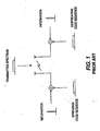
- FIG. 1 An example prior art communication system is shown in Figure 1 .
- the system employs a technique known as code division multipflexing, or more commonly, as code-division multiple access or CDMA.
- CDMA is a communication technique in which data is transmitted within a broadened band (spread spectrum) by modulating the data to be transmitted with a pseudo-noise signal.
- the data signal to be transmitted may have a bandwidth of only a few thousand Hertz distributed over a frequency band that may be several million Hertz.
- the communication channel may be used simultaneously by m independent subchannels. For each subchannel, all other subchannels appear as noise.
- a single subchannel of a given bandwidth is mixed with a unique spreading code which repeats a predetermined pattern generated by a wide bandwidth, pseudo-noise (pn) sequence generator.
- pn pseudo-noise
- These unique user spreading codes are typically orthogonal to one another such that the cross-correlation between the spreading codes is approximately zero.
- a data signal is modulated with the pn sequence to produce a digital spread spectrum signal.
- a carrier signal is then modulated with the digital spread spectrum signal, to establish a forward-link, and transmitted.
- a receiver demodulates the transmission and extracts the digital spread spectrum signal. The transmitted data is reproduced after correlation with the matching pn sequence.
- the received signal can be correlated with a particular user signal related to the particular spreading code such that only the desired user signal related to the particular spreading code is enhanced while the other signals for all other users are not enhanced.
- the same process is repeated to establish a reverse-link.
- a coherent modulation technique such as phase shift keying (PSK) is used for a plurality of subscriber units, whether stationary or mobile
- PSK phase shift keying
- a global pilot is continuously transmitted by the base station for synchronizing with the subscriber units.
- the subscriber units synchronize with the base station at all times and use the pilot signal information to estimate channel phase and magnitude parameters.
- a subscriber unit For initial acquisition by the base station to establish a reverse-link, a subscriber unit transmits a random access packet over a predetermined random access channel (RACH).
- RACH random access channel
- the random access packet serves two functions. The first function is for initial acquisition when the subscriber unit is transmitting and the base station has to receive the transmission quickly and determine what is received.
- the RACH initiates the reverse-link to the base station.
- the second use of random access packets is for communicating lower data rate information rather than consuming a dedicated continuous voice communication channel. Small amounts of data such as credit card information are included in the data portion of the random access packet instead of call placing data.
- the information when sent to the base station can be forwarded to another communicating user.
- a random access packet comprises a preamble portion and a data portion.
- the data may be transmitted in parallel with the preamble.
- the random access channel typically uses quadrature phase shift keying (QPSK) for the preamble and data.
- QPSK quadrature phase shift keying
- the base station examines the received preamble for the unique spreading codes. Each symbol of the RACH preamble is spread with a pn sequence. Using matched filters, the base station searches continuously for those codes that correlate. The data portion contains instructions for a desired service. The base station demodulates the data portion to determine what type of service is requested such as a voice call, fax, etc . The base station then proceeds by allocating a specific communication channel for the subscriber unit to use for the reverse-link and identifying the spreading codes for that channel. Once the communication channel is assigned, the RACH is released for other subscriber units to use. Additional RACHs afford quicker base station acquisition by eliminating possible collisions between subscriber units simultaneously initiating calls.
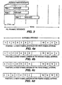
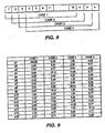
- An example prior art preamble signature is defined by 16 symbols.
- a table of sixteen coherent RACH preamble signatures is shown in Figure 2 . Since each symbol is a complex quantity and has a pulse shape comprising 256 chips of the spreading pn sequence, each signature comprises 4096 chips.
- the complete RACH preamble signature is transmitted at a chipping rate of 4096 chips per millisecond or 0.244 chips per microsecond.
- each subscriber unit receives frame boundary information. Depending upon the distance from the base station to a subscriber unit, the frame boundary information suffers a forward-link transmission delay.
- Table 1 illustrates the effect of round trip propagation delay.
- the first column is the distance in km between a mobile subscriber unit and a given base station.
- the second column is the round trip propagation delay of the RF signal in milliseconds from the base station to a subscriber unit and back.
- the third column shows the chip clocking position of the matched filter at the base station with time 0 referenced at the start of a transmitted frame boundary. The value represents when a first chip is received from a subscriber unit referencing the beginning of a frame boundary.
- the fourth column shows the expected location of the first output of the matched filter which occurs after assembling 256 received chips; (reference being made at the start of a frame boundary). A symbol may be output during any one of the first four symbol intervals depending on subscriber unit distance.
- the base station Since the base station is not synchronized with the subscriber unit and does not have a carrier reference, the base station does not know where in a received chip sequence the beginning of a RACH preamble symbol begins.
- the matched filter must correlate a total of 256 chips corresponding to a valid symbol pulse shape. As one skilled in this art knows, as the chips are received, the matched filter assembles 256 chips to produce a first output representative of the pulse shape. Consecutive outputs from the matched filter are generated for each subsequently received chip.
- the mobile subscriber unit transmits the preamble part first to access the RACH from the base station.
- One from among sixteen signatures is randomly selected and one from among five time-offsets is randomly chosen to account for the range ambiguity during transmission.
- the mobile subscriber unit constantly receives a frame boundary broadcast from the base station.
- the time-offset (value of n ) is chosen at random at each random access attempt.
- the present invention relates to a detector that detects a transmitted digital signature using the energy output from a matched filter in conjunction with normal correlation detection.
- the energies are tabulated according to an anticipated signature pattern for variable transmission distances.
- the tabulation accounts for expected round trip transmission delays and allows processing of the accumulated symbols to derive a correct signature whether coherent or non-coherent signature coding is used and whether or not multiple Doppler channels are present.
- Alternative embodiments of the invention include new schemes for differentially encoding RACH preamble signatures.
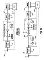
- a CDMA communication system 25 as shown in Figure 5 includes a transmitter 27 and a receiver 29 , which may reside in either a bass station or a mobile subscriber unit.
- the transmitter 27 includes a signal processor 31 which encodes voice and nonvoice signals 33 into data at various rates, e . g . 8 kbps, 16 kbps, 32 kbps, 64 kbps or other rates as desired for the particular application.
- the signal processor 31 selects a rate in dependence upon the type of signal, service or in response to a set data rate.
- the input data 33 which can be considered a bi-phase modulated signal is encoded using a forward error-correction (FEC) encoder 35 .
- FEC forward error-correction
- the single bi-phase modulated data signal becomes bivariate or two bi-phase modulated signals.
- One signal is designated the in-phase channel I 41a.
- the other signal is designated the quadrature channel Q 41b.
- Bi-phase modulated I and Q signals are usually referred to as QPSK.
- the two bi-phase modulated data or symbols 41a , 41b are spread with a complex pseudo-noise (pn) sequence 43a, 43b.
- the QPSK symbol stream 41a, 41b is multiplied by a unique complex pn sequence 43a, 43b.
- Both the I and Q pn sequences 43a, 43b are comprised of a bit stream generated at a much higher rate, typically 100 to 200 times the symbol rate.
- the complex pn sequence 43a, 43b is mixed at mixers 42a , 42b with the complex-symbol bit stream 41a, 41b to produce the digital spread signal 45a, 45b.
- the components of the spread signal 45a, 45b are known as chips having a much smaller duration.
- the resulting I 45a and Q 45b spread signals are upconverted to radio frequency by mixers 46a, 46b, and are combined at the combiner 53 with other spread signals (channels) having different spreading codes, mixed with a carrier signal 51 to upconvert the signal to RF, and radiated by antenna 54 as a transmitted broadcast signal 55 .
- the transmission 55 may contain a plurality of individual channels having different data rates.
- the receiver 29 includes a demodulator 57a, 57b which downcooverts the received revision of transmitted broadband signal 55 at antenna 56 into an intermediate carrier frequency 59a, 59b .
- a second down conversion at the mixers 58a, 58b reduces the signal to baseband.
- the QPSK signal is then filtered by the filters 61 and mixed at mixers 62a, 62b with the locally generated complex pn sequence 43a, 43b which matches the conjugate of the transmitted complex code. Only the original waveforms which were spread by the same code at the transmitter 27 will be effectively despread. All other received signals will appear as noise to the receiver 29.
- the data 65a, 65b is then passed to a signal processor 67 where FEC decoding is performed on the convolutionally encoded data.
- the baseband signal is at the chip level. Both the I and Q components of the signal are despread using the conjugate of the pn sequence used during spreading, returning the signal to the symbol level.
- the mobile subscriber unit transmits a random access packet transported on a RACH.
- the transmission of the RACH is similar to what was described except the RACH does not undergo FEC.
- FIG. 2 A table showing 16 possible coherent PSK coded RACH 71 preamble signatures 73 is shown in Figure 2 .
- Each signature comprises 16 symbols.
- a discussion of the coding methods and complex numbers is beyond the scope of this disclosure and is known to those skilled in this art.
- a prior art coherent RACH 71 detector 75 is shown in Figure 6A .
- the demodulated signal 77 is input to a matched filter 79 for despreading the RACH preamble 73 .
- the output of the matched filter 79 is coupled to a preamble correlator 81 for correlating the RACH preamble 73 with a known preamble pn sequence representing the preamble code 83 .
- the output of the preamble correlator 81 will have peaks 85 corresponding to the timing 87 of any received random access burst using the specific preamble code 83.
- the estimated timing 87 can then be used in an ordinary RAKE 89 combiner for the reception of the data part of the RACH 71 burst.
- this detector 75 may work well under ideal conditions with the coherent PSK coded preamble signatures 73 shown in Figure 2 , its operation may be adversely affected due to range ambiguity and the presence of Doppler.
- non-coherent detection can be utilized.
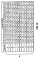
- the coherent RACH preamble signatures 73 shown in Figure 2 are differentially encoded, (i.e., differential phase shift keyed (DPSK) processed). Accordingly, the coherent preamble signatures 73 are first translated into incoherent, DPSK coded signals prior to transmission, and then differentially decoded after reception.
- DPSK differential phase shift keyed
- the remainder of the DPSK coding is performed for each consecutive symbol of a given preamble signature 73.
- the process translates all 16 preamble signatures 73 into the differential preamble signatures 97 shown in Figure 10 .
- the DPSK translation may be calculated and loaded into firmware as part of the mobile subscriber unit or may be calculated when initiating a call depending upon the sophistication of the base station receiver.
- the same process as hereinbefore described for coherent processing may performed except that the received signal must be recovered by differential decoding before correlating with the preamble signatures.
- a RACH detector 101 made in accordance with present invention 95 is shown in Figure 6 B.
- the received RACH 77 is demodulated and coupled to the input of the matched filter 79.
- the output of the matched filter 79 is coupled to the RAKE 89, to a time delay 103 and a first mixer 105.
- Each received signature 97 is delayed by one symbol length, which is 256 chips.
- the output of the time delay 103 is coupled to conjugate processor 107 which converts the received symbol to its complex conjugate.
- the output of the complex conjugate processor 107 is coupled to the first mixer 105 where the real part of the complex number is selected 106 and multiplied by the signature symbol and output to the preamble correlator 81 .
- the preamble correlator 81 correlates a possible signature with a sequence of outputs. This sum is compared to a threshold in the peak detector 85 and if it exceeds the threshold by the end of the sixteenth symbol, it is determined that a signature has been detected. Since there are 16 computations, one for each signature, there may be more than one accumulation that exceeds its threshold for a given sample time. In this case, the accumulation with the largest value is selected as correct.
- the estimated timing 87 can then be used in an ordinary RAKE 89 combiner for the reception of the data part of the RACH 71 burst.
- the energy from each output of the RACH detector matched filter 79 is computed.
- the matched filter 79 is typically sampled at the chipping rate, it may be oversampled at twice or four times the chipping rate, (or even higher).
- the chipping rate is 4.096 million chips per second, or one chip every 0.244 ⁇ s.
- Shown in Figure 7A is a memory matrix 101 stored in RAM 100 where the value of the energy computed for each symbol output from the matched filter 79 is stored.
- the matrix 101 is arranged to store all possible delayed symbol values corresponding to base station to subscriber unit transmission distances ranging from 100m to 30km.
- the matrix 101 consists of 256 rows (0-255) 102 and 19 columns (0-18) 104 representing the total number of chips transmitted during a RACH preamble signature. If the subscriber unit were located adjacent to the base station where propagation delay would be negligible, the first symbol would be output after 256 chips were received or at P (255,0). If the subscriber unit were located at 30km, the first symbol would be output after 819 chips were received or at approximately P (54,4).
- the matrix 101 allows for three additional symbol outputs to anticipate range ambiguity, (shown in Figure 4 , as will be explained in greater detail hereinafter). Once the matrix 101 is populated, it includes all samples of interest for the mobile subscriber unit out to a range of 30 km.
- a match filter output is expected to produce a larger than average output 16 times, each larger value separated from the previous one by 256 chips.
- the combined output is the sum of the matched filter outputs speed by 256 chips.
- One problem that must be overcome is that the first matched filter output does not automatically occur within the first 256 chips. It can occur later, as shown in Table 1, depending upon the distance between the mobile subscriber unit and the base station.
- a preamble signature When a preamble signature is present, its corresponding matched filter outputs will fill 16 of the 19 elements of one of the 256 rows 102 . For each row, a complete preamble signature may be detected where the value of total energy summed for the row exceeds a predetermined threshold.
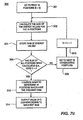
- the procedure 200 for tentatively detecting preamble signatures is shown.
- the value of energy for each row is summed 109 and similarly stored (step 202).
- the row is considered to be a "tentative detection”.
- the sum for the first row is compared to a predetermined threshold (step 204 ) to determine if the sum exceeds the threshold (step 206). If so, the row is marked as a tentative detection (step 208). If each row has not been summed (step 210 ), the next row is retrieved (step 212) and the process is repeated ( steps 206-210). Once all the rows have been summed, the range ambiguity on each tentative detection is resolved (step 214), (which will be described in greater detail hereinafter), and the candidates are output (step 216).
- range ambiguity is introduced whereby the preamble signature may not occur for up to four symbols. This range ambiguity must be resolved. Accordingly, for each row marked as a tentative detection, the value of the energy of the 16 consecutive positions within that row which produce the highest sum must be determined. Due to range ambiguity, four possible cases 1,2,3 and 4 are derived from a received version of a preamble signature. The four cases are shown in Figure 8 . In this example, signature 1 was transmitted and assembled from nineteen received symbols, forming one row of the memory matrix 101 . For each case, sixteen consecutive symbols out of nineteen are correlated with each of the sixteen possible preamble signatures, resulting in 64 hypotheses.
- One of the 64 hypotheses will result in a signature having the greatest energy received.
- the greatest of the 64 hypotheses will occur in case 1 since case 1 has all consecutive symbols and does not include noise.
- Cases 2, 3 and 4 include symbols derived from noise components and will not correlate with one of the sixteen preamble signatures.
- each row comprises 19 total positions.
- the values of the energy of the first 16 consecutive positions of a row considered to be a tentative detection are analyzed (step 301).
- the energy sum for the 16 positions is calculated (step 302 ) and then stored (step 304 ). If the sums of all positions within the row have not been calculated (step 306 ) the next 16 consecutive positions, corresponding to elements 2-17, are reviewed (step 308 ).
- the counter is then incremented ( step 310 ) and the procedure is then repeated ( step 302-306).
- step 312 the system then outputs the value of the column (k) corresponding to the beginning of the 16 consecutive positions having the greatest sum (step 314). This is a selected candidate. This procedure is repeated for each tentative detection.
- the selected candidates are compared with the output of a normal correlation detection process for coherent or incoherent PSK coding.
- the discussion of a normal correlation detection process is beyond the scope of this application and is well known to those skilled in this art.
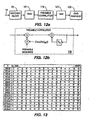
- the first column is the signature with which a received signal correlates.
- the second though fifth columns are the correlation values of cases 1-4. The larger the correlation value, the better the received match to the received signal.
- a zero correlation value indicates the received symbol is orthogonal to the respective signature symbol. As can clearly be seen, orthogonality does not exist among the respective signatures for cases 2, 3 and 4.
- a RACH detector 95 made in accordance with this embodiment of the present invention is shown in Figure 11 .
- the received RACH 77 is demodulated and coupled to the input of the matched filter 79.
- the output of the matched filter 79 is coupled to the RAKE 89 , to a time delay unit 103 , a first mixer 105 , and a first processor 99 .
- Each received preamble signature 97 is delayed by one symbol length T s , which is 256 chips, in the delay unit 103 .
- the output of the time delay unit 103 is coupled to conjugate processor 107 which converts the received symbol to its complex conjugate.
- the output of the complex conjugate processor 107 is coupled to the first mixer 105 where the real part of the complex number is multiplied by the preamble signature symbol and output to the preamble correlator 81.
- the preamble correlator 81 correlates a possible signature with a sequence of outputs based on the symbol sequence. This sum is compared to a threshold, and if it exceeds the threshold by the end of the sixteenth symbol, a signature is detected. Since there are 16 computations, one for each signature, there may be more than one accumulation that exceeds its threshold for a given sample time. In that case, the accumulation with the largest value is selected as correct.
- the matched filter 79 output 97 is input to the first processor 99 which computes the value of the energy for each symbol output. For each energy value computed, it is stored in the memory matrix 101. As previously described, after the energy values have been computed for a row of 19 symbols, a second processor 109 computes the summed energy for that given row which is then stored in a second memory 111. It should be noted that the memory matrix 101 and the second memory 111 may actually comprise a single RAM memory, instead of two separate components as shown. The energy exceeding a predetermined threshold is a tentative detection.
- a third processor 113 compares the 256 energy levels to normal signature detection on a one-to-one basis, thereby cross-verifying the results of each process to arrive at the correct signature sequence received.
- an alternative embodiment resolves the channels similar to the four case approach discussed above.
- a phase rotation is introduced. The phase rotation corrects and compensates the phase changes experienced due to Doppler spreading.
- m ⁇ 4 ⁇ 16 hypotheses are created. The greatest of m ⁇ 4 ⁇ 16 hypotheses is selected and the corresponding signature is identified.
- each case is then correlated with 16 signatures with m different phase rotations corresponding to m Doppler channels.
- Each case generates m ⁇ 16 hypotheses.
- Four cases create m ⁇ 16 ⁇ 4 hypotheses.
- the preamble signature with the greatest correspondence to m ⁇ 16 ⁇ 4 hypotheses is selected.
- FIG. 12A A receiver using coherent detection with multiple Doppler channels made in accordance with this embodiment of the present invention is shown in Figures 12A - B .
- the received RACH 77 is coupled to the matched filter 79 to correlate with a spreading code (256 chips).
- a spreading code 256 chips.
- one symbol is output from the matched filter every 256 chips until nineteen symbol outputs are collected and stored in the memory matrix 101 . Sixteen consecutive symbol outputs among nineteen symbol outputs are assembled and the four cases are formed.
- An alternative embodiment of the present invention is based on the 16 x 16 signature matrix shown in Figure 13 .
- a new signature set is created by differentially encoding the signature matrix set forth in Figure 13 .
- the encoding rule is as follows. First, S(i,k), M(i,k) and R(i,k) are defined as:
- Figure 14 shows an original uncoded sequence and its transformation into a differentially encoded sequence.
Claims (6)
- Procédé à utiliser lors du traitement d'un préambule d'un signal de canal d'accès aléatoire, RACH, le procédé comprenant de:sélectionner une parmi une pluralité de signatures de préambule prédéterminées;produire un code basé sur la signature de préambule sélectionnée; etappliquer une rotation de phase au code produit afin d'implémenter un effet Doppler pour produire un signal de signature de préambule traité;dans lequel le signal de signature de préambule traité est utilisé lors du traitement du signal RACH.
- Procédé selon la revendication 1, dans lequel le signal de signature de préambule traité est utilisé à des fins de corrélation avec une séquence reçue.
- Procédé selon la revendication 1, dans lequel le signal de signature de préambule traité est utilisé pour résoudre l'effet Doppler résultant d'un transfert sans fil du signal RACH à travers le RACH.
- Unité d'abonné à utiliser lors du traitement d'un préambule d'un signal de canal d'accès aléatoire, RACH:un moyen pour sélectionner une signature parmi des signatures de préambule prédéterminées;un moyen pour produire un code basé sur la signature de préambule sélectionnée;un moyen pour produire un signal de signature de préambule traité; etun moyen pour traiter le signal RACH en utilisant le signal de signature de préambule traité.
- Unité d'abonné selon la revendication 4, dans laquelle le signal de signature de préambule traité est utilisé en vue d'une corrélation avec une séquence reçue.
- Unité d'abonné selon la revendication 4, dans lequel le signal de signature de préambule traité est utilisé pour résoudre un effet Doppler résultant d'un transfert sans fil du signal RACH à travers le RACH.
Applications Claiming Priority (6)
| Application Number | Priority Date | Filing Date | Title |
|---|---|---|---|
| US11229998P | 1998-12-14 | 1998-12-14 | |
| US11628499P | 1999-01-19 | 1999-01-19 | |
| US12541899P | 1999-03-22 | 1999-03-22 | |
| US12917799P | 1999-04-14 | 1999-04-14 | |
| EP20030003570 EP1311075B9 (fr) | 1998-12-14 | 1999-12-14 | Détection de préambule pour canaux à accès aléatoire |
| EP19990968880 EP1142149B1 (fr) | 1998-12-14 | 1999-12-14 | Detection de preambule pour canaux a acces aleatoire |
Related Parent Applications (4)
| Application Number | Title | Priority Date | Filing Date |
|---|---|---|---|
| EP19990968880 Division EP1142149B1 (fr) | 1998-12-14 | 1999-12-14 | Detection de preambule pour canaux a acces aleatoire |
| EP20030003570 Division EP1311075B9 (fr) | 1998-12-14 | 1999-12-14 | Détection de préambule pour canaux à accès aléatoire |
| EP99968880.7 Division | 1999-12-14 | ||
| EP03003570.3 Division | 2003-02-17 |
Publications (2)
| Publication Number | Publication Date |
|---|---|
| EP2296288A1 EP2296288A1 (fr) | 2011-03-16 |
| EP2296288B1 true EP2296288B1 (fr) | 2012-10-17 |
Family
ID=27493852
Family Applications (3)
| Application Number | Title | Priority Date | Filing Date |
|---|---|---|---|
| EP20030003570 Expired - Lifetime EP1311075B9 (fr) | 1998-12-14 | 1999-12-14 | Détection de préambule pour canaux à accès aléatoire |
| EP19990968880 Expired - Lifetime EP1142149B1 (fr) | 1998-12-14 | 1999-12-14 | Detection de preambule pour canaux a acces aleatoire |
| EP20100180731 Expired - Lifetime EP2296288B1 (fr) | 1998-12-14 | 1999-12-14 | Détection de préambule de canal d'accès aléatoire |
Family Applications Before (2)
| Application Number | Title | Priority Date | Filing Date |
|---|---|---|---|
| EP20030003570 Expired - Lifetime EP1311075B9 (fr) | 1998-12-14 | 1999-12-14 | Détection de préambule pour canaux à accès aléatoire |
| EP19990968880 Expired - Lifetime EP1142149B1 (fr) | 1998-12-14 | 1999-12-14 | Detection de preambule pour canaux a acces aleatoire |
Country Status (12)
| Country | Link |
|---|---|
| US (5) | US7529210B2 (fr) |
| EP (3) | EP1311075B9 (fr) |
| JP (4) | JP4355107B2 (fr) |
| KR (1) | KR100661378B1 (fr) |
| CN (3) | CN1129241C (fr) |
| AT (2) | ATE542307T1 (fr) |
| AU (1) | AU2708400A (fr) |
| DE (3) | DE1311075T1 (fr) |
| DK (1) | DK1142149T3 (fr) |
| ES (3) | ES2209685T1 (fr) |
| HK (4) | HK1041573B (fr) |
| WO (1) | WO2000036761A2 (fr) |
Cited By (1)
| Publication number | Priority date | Publication date | Assignee | Title |
|---|---|---|---|---|
| DE102013011914B3 (de) * | 2013-07-17 | 2014-10-16 | Mbda Deutschland Gmbh | Datenübertragungsverfahren für Kanäle mit schnellveränderlichen Übertragungseigencohaften |
Families Citing this family (58)
| Publication number | Priority date | Publication date | Assignee | Title |
|---|---|---|---|---|
| DK1142149T3 (da) * | 1998-12-14 | 2004-07-26 | Interdigital Tech Corp | Random-access-kanal præambeldetektering |
| EP1109326A1 (fr) * | 1999-12-15 | 2001-06-20 | Lucent Technologies Inc. | Détecteur de préambule pour un récepteur AMRC |
| JP3438701B2 (ja) * | 2000-06-09 | 2003-08-18 | 日本電気株式会社 | Ds−cdmaシステムにおける受信パスタイミング検出回路 |
| US6765974B1 (en) * | 2000-07-19 | 2004-07-20 | Radwin Ltd. | Rach starting time vicinity estimation |
| KR100436296B1 (ko) * | 2000-10-06 | 2004-06-18 | 주식회사 에이로직스 | 신호 획득을 위한 프리앰블 서치장치 및 그 방법 |
| JP4493830B2 (ja) * | 2000-10-23 | 2010-06-30 | 株式会社日立国際電気 | Rach受信装置 |
| US20020097780A1 (en) * | 2000-11-30 | 2002-07-25 | Odenwalder Joseph P. | Preamble generation |
| JP2003152600A (ja) * | 2001-11-15 | 2003-05-23 | Nec Corp | 固定パターン検出装置、固定パターン検出方法、無線基地局および無線移動局 |
| KR100446532B1 (ko) * | 2001-12-10 | 2004-09-01 | 삼성전자주식회사 | 유엠티에스에서의 기지국 접속시간 감소 방법 |
| DE60306298T2 (de) * | 2002-10-25 | 2007-04-26 | Matsushita Electric Industrial Co., Ltd., Kadoma | Schaltung, Empfänger und Verfahren zur Phasenfehlerkorrektur unter Auswahl eines innerhalb der Präambel gemessenen Phasenfehlers in Abhängigkeit des zeitlichen Auftretens eines Einzelwortes |
| CN100353802C (zh) * | 2004-06-28 | 2007-12-05 | 华为技术有限公司 | 一种自动统计小区覆盖范围的方法 |
| CN100506916C (zh) * | 2004-10-15 | 2009-07-01 | 三芳化学工业股份有限公司 | 高分子片材及其制造方法 |
| US7986946B2 (en) * | 2005-06-29 | 2011-07-26 | Telefonaktiebolaget Lm Ericsson (Publ) | Evaluation of random access preamble codes |
| WO2007010331A1 (fr) * | 2005-07-19 | 2007-01-25 | Telefonaktiebolaget Lm Ericsson (Publ) | Detection de preambule |
| CN100373796C (zh) * | 2005-10-28 | 2008-03-05 | 北京威讯紫晶科技有限公司 | 短程无线网络中接收数据的同步处理方法 |
| US7450944B2 (en) * | 2005-11-03 | 2008-11-11 | Motorola, Inc. | Method and apparatus for base station synchronization |
| GB2469229B (en) * | 2005-11-04 | 2011-02-02 | Nec Corp | Wireless communication system and method of controlling a transmission power |
| US8000305B2 (en) * | 2006-01-17 | 2011-08-16 | Motorola Mobility, Inc. | Preamble sequencing for random access channel in a communication system |
| US9301318B2 (en) * | 2006-01-20 | 2016-03-29 | Nokia Technologies Oy | Random access procedure with enhanced coverage |
| WO2007099800A1 (fr) * | 2006-02-28 | 2007-09-07 | Nec Corporation | Systeme de commande de minutage de transmission, son procede et station mobile utilisee dedans |
| US8009637B2 (en) * | 2006-03-10 | 2011-08-30 | Motorola Solutions, Inc. | Method and apparatus for spreading channel code selection |
| KR20070095583A (ko) * | 2006-03-21 | 2007-10-01 | 삼성전자주식회사 | 이동통신 시스템에서 메시지 전송 장치 및 방법 |
| WO2007126013A1 (fr) * | 2006-04-28 | 2007-11-08 | Panasonic Corporation | Systeme de communication radio, station mobile et procede de transmission rach |
| JP4732948B2 (ja) * | 2006-05-01 | 2011-07-27 | 株式会社エヌ・ティ・ティ・ドコモ | 送信装置および受信装置並びにランダムアクセス制御方法 |
| KR100956755B1 (ko) * | 2006-05-03 | 2010-05-12 | 삼성전자주식회사 | 광대역무선접속 시스템에서 신호구분을 위한 장치 및 방법 |
| TWI690179B (zh) | 2006-06-09 | 2020-04-01 | 美商進化無線責任有限公司 | 行動通訊系統中傳送資料之方法和裝置 |
| KR101233172B1 (ko) | 2006-06-26 | 2013-02-15 | 엘지전자 주식회사 | 랜덤 액세스 채널을 통한 데이터 송수신 방법 |
| BRPI0713703B1 (pt) | 2006-06-15 | 2020-10-13 | Godo Kaisha Ip Bridge 1 | estação móvel para transmitir um preâmbulo de acesso randômico |
| EP2048792A1 (fr) | 2006-08-03 | 2009-04-15 | Panasonic Corporation | Procédé et dispositif d'émission radio |
| KR100937423B1 (ko) * | 2006-09-26 | 2010-01-18 | 엘지전자 주식회사 | 반복형 시퀀스 생성 방법 및 이를 이용한 신호 송신 방법 |
| CN102984824B (zh) * | 2006-09-29 | 2015-12-23 | 松下电器(美国)知识产权公司 | 终端装置和终端装置执行的发送方法 |
| CN104320167B (zh) * | 2006-11-06 | 2017-11-14 | 高通股份有限公司 | 用于功率分配和/或速率选择的方法和装置 |
| US8160189B2 (en) * | 2007-01-26 | 2012-04-17 | Raytheon Company | Method and system for communication channel characterization |
| US7974373B2 (en) * | 2007-03-13 | 2011-07-05 | Pine Valley Investments, Inc. | Method and architecture for digital pulse shaping and rate conversion |
| WO2008114967A1 (fr) * | 2007-03-16 | 2008-09-25 | Lg Electronics Inc. | Procédé de génération de préambules d'accès aléatoire dans un système de communication sans fil |
| KR20080084536A (ko) | 2007-03-16 | 2008-09-19 | 엘지전자 주식회사 | 무선통신 시스템에서 제어정보 전송 방법 |
| US9113325B2 (en) * | 2007-04-25 | 2015-08-18 | Texas Instruments Incorporated | Signaling of random access preamble time-frequency location in wireless networks |
| CN101299620A (zh) | 2007-04-30 | 2008-11-05 | 华为技术有限公司 | 确定零相关区长度集合的方法、装置及移动通信系统 |
| KR20080097327A (ko) * | 2007-05-01 | 2008-11-05 | 엘지전자 주식회사 | 시퀀스 세트 구성 방법 및 이를 이용한 임의접속 방법 |
| KR101519345B1 (ko) | 2008-01-01 | 2015-05-21 | 주식회사 팬택 | 랜덤 액세스 요청 송수신 및 랜덤 액세스 응답 송수신 방법 |
| KR101447750B1 (ko) * | 2008-01-04 | 2014-10-06 | 엘지전자 주식회사 | 랜덤 액세스 과정을 수행하는 방법 |
| JP5029450B2 (ja) | 2008-03-21 | 2012-09-19 | 富士通株式会社 | 通信システムおよび端末装置 |
| ATE528953T1 (de) * | 2008-06-19 | 2011-10-15 | Ericsson Telefon Ab L M | Verfahren und vorrichtungen zum durchführen von direktzugriff in einem telekommunikationssystem |
| CN101295999B (zh) * | 2008-06-27 | 2014-02-19 | 中兴通讯股份有限公司 | 一种随机接入前导的检测方法 |
| US8228971B2 (en) * | 2008-07-29 | 2012-07-24 | Agere Systems Inc. | Technique for searching for a preamble signal in a spread spectrum signal using a fast Hadamard transform |
| US8660165B2 (en) * | 2009-06-11 | 2014-02-25 | Andrew Llc | System and method for detecting spread spectrum signals in a wireless environment |
| US8223821B2 (en) | 2009-06-25 | 2012-07-17 | Andrew Llc | Uplink signal detection in RF repeaters |
| CN101997590B (zh) * | 2009-08-10 | 2014-06-11 | 中兴通讯股份有限公司 | 随机接入信号的检测方法和基带处理板以及基站 |
| KR101234311B1 (ko) * | 2011-04-28 | 2013-02-18 | 한국해양과학기술원 | 차동변조 방식을 사용하는 패킷 데이터 통신에서 프리앰블에 부가정보를 전송하는 송신장치와 방법 |
| DE102011100471A1 (de) * | 2011-05-04 | 2012-11-08 | Rheinmetall Defence Electronics Gmbh | Verfahren und Vorrichtung zur passiven Analyse einer Zweiwege-Kommunikation |
| US9204467B2 (en) * | 2012-12-11 | 2015-12-01 | Blackberry Limited | Communicating encoded traffic data |
| CN105745888B (zh) | 2013-10-29 | 2019-11-26 | 三星电子株式会社 | 使用用于向相干和非相干接收器同时传输的三进制序列的方法和系统 |
| KR102345071B1 (ko) | 2013-10-30 | 2021-12-30 | 삼성전자주식회사 | 가변 확산 인자들을 갖는 확산 시퀀스들을 선택하기 위한 방법 및 시스템 |
| CN117336883A (zh) | 2018-10-30 | 2024-01-02 | 交互数字专利控股公司 | 距离相关随机接入信道(rach)前导码选择 |
| WO2020034582A1 (fr) | 2019-01-17 | 2020-02-20 | Zte Corporation | Transmissions de charge utile basées sur un conflit à l'aide d'un codage différentiel |
| US11031961B2 (en) * | 2019-07-16 | 2021-06-08 | Microsoft Technology Licensing, Llc | Smart symbol changes for optimization of communications using error correction |
| CN111555797B (zh) * | 2020-04-23 | 2022-02-15 | 中国电子科技集团公司第五十四研究所 | 一种卫星移动通信系统rach突发的解调方法 |
| CN113810162B (zh) * | 2021-09-17 | 2023-04-11 | 四川安迪科技实业有限公司 | 一种含前导随机突发信号的存在性检测方法 |
Family Cites Families (40)
| Publication number | Priority date | Publication date | Assignee | Title |
|---|---|---|---|---|
| US4930140A (en) * | 1989-01-13 | 1990-05-29 | Agilis Corporation | Code division multiplex system using selectable length spreading code sequences |
| US5253268A (en) * | 1990-05-24 | 1993-10-12 | Cylink Corporation | Method and apparatus for the correlation of sample bits of spread spectrum radio signals |
| US5263268A (en) * | 1992-01-13 | 1993-11-23 | Savant Instruments, Inc. | Vacuum drying system with cryopumping of solvent recovery feature |
| US5550809A (en) * | 1992-04-10 | 1996-08-27 | Ericsson Ge Mobile Communications, Inc. | Multiple access coding using bent sequences for mobile radio communications |
| JPH11501468A (ja) | 1994-12-12 | 1999-02-02 | エリクソン インコーポレイテッド | モービル通信システムにおけるダイバーシティ指向型チャネル割当 |
| JPH08237169A (ja) * | 1995-02-24 | 1996-09-13 | Hitachi Ltd | プリアンブル同期方式 |
| SE515752C2 (sv) * | 1995-08-28 | 2001-10-08 | Telia Ab | Direktåtkomst i OFDM-system |
| FI102447B (fi) * | 1996-02-06 | 1998-11-30 | Nokia Telecommunications Oy | Yhteydenmuodostusmenetelmä, tilaajapäätelaite ja radiojärjestelmä |
| US5822311A (en) * | 1996-03-05 | 1998-10-13 | Ericsson Inc. | Random access scheme for mobile satellite communications |
| US5696762A (en) * | 1996-03-25 | 1997-12-09 | Stanford Telecommunications, Inc. | Rapid-acquisition access channel scheme for CDMA systems |
| US6259724B1 (en) | 1996-10-18 | 2001-07-10 | Telefonaktiebolaget L M Ericsson (Publ) | Random access in a mobile telecommunications system |
| US6049576A (en) * | 1996-10-29 | 2000-04-11 | Stanford Telecommunications, Inc. | Kronecker product code acquisition system |
| US6222828B1 (en) * | 1996-10-30 | 2001-04-24 | Trw, Inc. | Orthogonal code division multiple access waveform format for use in satellite based cellular telecommunications |
| JPH10233758A (ja) * | 1997-02-20 | 1998-09-02 | Nippon Telegr & Teleph Corp <Ntt> | 無線通信方法および装置 |
| JP3570843B2 (ja) * | 1997-03-21 | 2004-09-29 | 日本電気エンジニアリング株式会社 | 位相変調器 |
| WO1998049859A1 (fr) * | 1997-04-30 | 1998-11-05 | Qualcomm Incorporated | Procede et dispositif de surveillance des delais de propagation entre une station de base et un poste d'abonne |
| US6163533A (en) * | 1997-04-30 | 2000-12-19 | Telefonaktiebolaget Lm Ericsson (Publ) | Random access in a mobile telecommunications system |
| JP3797510B2 (ja) * | 1997-07-16 | 2006-07-19 | ソニー株式会社 | 通信方法、送信装置、受信装置及びセルラー無線通信システム |
| JP3726986B2 (ja) * | 1997-08-07 | 2005-12-14 | ソニー株式会社 | 通信方法、送信装置、受信装置及びセルラー無線通信システム |
| US6167056A (en) * | 1997-11-10 | 2000-12-26 | Qualcomm Incorporated | Access channel slot sharing |
| US6240073B1 (en) * | 1997-11-14 | 2001-05-29 | Shiron Satellite Communications (1996) Ltd. | Reverse link for a satellite communication network |
| FI105741B (fi) | 1998-02-12 | 2000-09-29 | Nokia Networks Oy | Tiedonsiirtomenetelmä ja radiojärjestelmä |
| US6363105B1 (en) | 1998-02-17 | 2002-03-26 | Ericsson Inc. | Flexible sliding correlator for direct sequence spread spectrum systems |
| US6643275B1 (en) | 1998-05-15 | 2003-11-04 | Telefonaktiebolaget Lm Ericsson (Publ) | Random access in a mobile telecommunications system |
| US6310869B1 (en) * | 1998-08-31 | 2001-10-30 | Qualcomm Incorporated | Method and apparatus for reducing amplitude variations and interference in communication signals, such as in wireless communication signals employing inserted pilot symbols |
| US6606313B1 (en) | 1998-10-05 | 2003-08-12 | Telefonaktiebolaget Lm Ericsson (Publ) | Random access in a mobile telecommunications system |
| US6757293B1 (en) * | 1998-12-02 | 2004-06-29 | Lucent Technologies Inc. | Methods and apparatus for providing short RACH frames for fast latency |
| DK1142149T3 (da) * | 1998-12-14 | 2004-07-26 | Interdigital Tech Corp | Random-access-kanal præambeldetektering |
| US6707819B1 (en) | 1998-12-18 | 2004-03-16 | At&T Corp. | Method and apparatus for the encapsulation of control information in a real-time data stream |
| JP3699602B2 (ja) * | 1999-01-07 | 2005-09-28 | 富士通株式会社 | プリディストーション装置及びその方法 |
| JP3796381B2 (ja) * | 1999-01-26 | 2006-07-12 | 株式会社エスアイアイ・マイクロパーツ | 電気二重層キャパシタ |
| US6169759B1 (en) | 1999-03-22 | 2001-01-02 | Golden Bridge Technology | Common packet channel |
| US6549564B1 (en) | 1999-04-08 | 2003-04-15 | Telefonaktiebolaget Lm Ericsson (Publ) | Random access in a mobile telecommunications system |
| JP2000292746A (ja) * | 1999-04-08 | 2000-10-20 | Hitachi Ltd | 光学ブロック |
| US7173919B1 (en) | 1999-06-11 | 2007-02-06 | Texas Instruments Incorporated | Random access preamble coding for initiation of wireless mobile communications sessions |
| US6175559B1 (en) | 1999-07-07 | 2001-01-16 | Motorola, Inc. | Method for generating preamble sequences in a code division multiple access system |
| US6757831B1 (en) * | 1999-08-18 | 2004-06-29 | Sun Microsystems, Inc. | Logic block used to check instruction buffer configuration |
| EP1109326A1 (fr) * | 1999-12-15 | 2001-06-20 | Lucent Technologies Inc. | Détecteur de préambule pour un récepteur AMRC |
| JP4493830B2 (ja) * | 2000-10-23 | 2010-06-30 | 株式会社日立国際電気 | Rach受信装置 |
| KR20070095583A (ko) * | 2006-03-21 | 2007-10-01 | 삼성전자주식회사 | 이동통신 시스템에서 메시지 전송 장치 및 방법 |
-
1999
- 1999-12-14 DK DK99968880T patent/DK1142149T3/da active
- 1999-12-14 WO PCT/US1999/029504 patent/WO2000036761A2/fr active IP Right Grant
- 1999-12-14 EP EP20030003570 patent/EP1311075B9/fr not_active Expired - Lifetime
- 1999-12-14 AT AT03003570T patent/ATE542307T1/de active
- 1999-12-14 ES ES03003570T patent/ES2209685T1/es active Pending
- 1999-12-14 ES ES10180731T patent/ES2397266T3/es not_active Expired - Lifetime
- 1999-12-14 ES ES99968880T patent/ES2219107T3/es not_active Expired - Lifetime
- 1999-12-14 JP JP2000588907A patent/JP4355107B2/ja not_active Expired - Fee Related
- 1999-12-14 DE DE2003003570 patent/DE1311075T1/de active Pending
- 1999-12-14 KR KR1020017007370A patent/KR100661378B1/ko not_active IP Right Cessation
- 1999-12-14 EP EP19990968880 patent/EP1142149B1/fr not_active Expired - Lifetime
- 1999-12-14 AT AT99968880T patent/ATE262239T1/de not_active IP Right Cessation
- 1999-12-14 CN CN99814400A patent/CN1129241C/zh not_active Expired - Fee Related
- 1999-12-14 EP EP20100180731 patent/EP2296288B1/fr not_active Expired - Lifetime
- 1999-12-14 CN CNB2004101049011A patent/CN100375411C/zh not_active Expired - Fee Related
- 1999-12-14 AU AU27084/00A patent/AU2708400A/en not_active Abandoned
- 1999-12-14 DE DE1999968880 patent/DE1142149T1/de active Pending
- 1999-12-14 CN CNB031216293A patent/CN1299437C/zh not_active Expired - Fee Related
- 1999-12-14 DE DE69915689T patent/DE69915689T2/de not_active Expired - Lifetime
-
2002
- 2002-03-05 HK HK02101697.2A patent/HK1041573B/zh not_active IP Right Cessation
-
2004
- 2004-06-14 JP JP2004175917A patent/JP4589662B2/ja not_active Expired - Fee Related
- 2004-11-03 HK HK04108651A patent/HK1065903A1/xx not_active IP Right Cessation
-
2005
- 2005-12-15 HK HK05111526A patent/HK1076945A1/xx not_active IP Right Cessation
- 2005-12-16 US US11/305,283 patent/US7529210B2/en not_active Expired - Fee Related
-
2006
- 2006-12-13 JP JP2006335581A patent/JP4589911B2/ja not_active Expired - Fee Related
-
2009
- 2009-04-27 US US12/430,414 patent/US8036180B2/en not_active Expired - Fee Related
- 2009-12-07 JP JP2009277866A patent/JP4681665B2/ja not_active Expired - Fee Related
-
2010
- 2010-06-03 US US12/793,060 patent/US8218508B2/en not_active Expired - Fee Related
-
2011
- 2011-09-16 HK HK11109778A patent/HK1155573A1/xx not_active IP Right Cessation
-
2012
- 2012-07-09 US US13/544,388 patent/US8958397B2/en not_active Expired - Fee Related
-
2014
- 2014-12-22 US US14/579,282 patent/US9276669B2/en not_active Expired - Fee Related
Cited By (2)
| Publication number | Priority date | Publication date | Assignee | Title |
|---|---|---|---|---|
| DE102013011914B3 (de) * | 2013-07-17 | 2014-10-16 | Mbda Deutschland Gmbh | Datenübertragungsverfahren für Kanäle mit schnellveränderlichen Übertragungseigencohaften |
| EP2827544A2 (fr) | 2013-07-17 | 2015-01-21 | MBDA Deutschland GmbH | Procédé de transmission de données pour canaux ayant des propriétés de transmission changeant rapidement |
Also Published As
Similar Documents
| Publication | Publication Date | Title |
|---|---|---|
| EP2296288B1 (fr) | Détection de préambule de canal d'accès aléatoire | |
| US7103027B2 (en) | Random access channel preamble detection | |
| US5822359A (en) | Coherent random access channel in a spread-spectrum communication system and method | |
| JP3658402B2 (ja) | スペクトル拡散通信システム内における基地局への同期化とコード取得 | |
| US20040258131A1 (en) | Parallel spread spectrum communication system and method | |
| US20020191676A1 (en) | Parallel spread spectrum communication system and method | |
| US6526103B1 (en) | Multi-stage receiver | |
| US7701996B1 (en) | Methods and apparatus implementing short and long code channel overlay for fast acquistion of long PN codes in spread spectrum communications systems | |
| AU2002244019A1 (en) | System and method for spread spectrum communication using orthogonal coding |
Legal Events
| Date | Code | Title | Description |
|---|---|---|---|
| PUAI | Public reference made under article 153(3) epc to a published international application that has entered the european phase |
Free format text: ORIGINAL CODE: 0009012 |
|
| 17P | Request for examination filed |
Effective date: 20100928 |
|
| AC | Divisional application: reference to earlier application |
Ref document number: 1142149 Country of ref document: EP Kind code of ref document: P Ref document number: 1311075 Country of ref document: EP Kind code of ref document: P |
|
| AK | Designated contracting states |
Kind code of ref document: A1 Designated state(s): AT BE CH CY DE DK ES FI FR GB GR IE IT LI LU MC NL PT SE |
|
| RIC1 | Information provided on ipc code assigned before grant |
Ipc: H04B 1/707 20110101AFI20120229BHEP |
|
| REG | Reference to a national code |
Ref country code: HK Ref legal event code: DE Ref document number: 1155573 Country of ref document: HK |
|
| GRAP | Despatch of communication of intention to grant a patent |
Free format text: ORIGINAL CODE: EPIDOSNIGR1 |
|
| GRAS | Grant fee paid |
Free format text: ORIGINAL CODE: EPIDOSNIGR3 |
|
| GRAA | (expected) grant |
Free format text: ORIGINAL CODE: 0009210 |
|
| AC | Divisional application: reference to earlier application |
Ref document number: 1311075 Country of ref document: EP Kind code of ref document: P Ref document number: 1142149 Country of ref document: EP Kind code of ref document: P |
|
| AK | Designated contracting states |
Kind code of ref document: B1 Designated state(s): AT BE CH CY DE DK ES FI FR GB GR IE IT LI LU MC NL PT SE |
|
| REG | Reference to a national code |
Ref country code: GB Ref legal event code: FG4D |
|
| REG | Reference to a national code |
Ref country code: CH Ref legal event code: EP |
|
| REG | Reference to a national code |
Ref country code: IE Ref legal event code: FG4D |
|
| REG | Reference to a national code |
Ref country code: AT Ref legal event code: REF Ref document number: 580290 Country of ref document: AT Kind code of ref document: T Effective date: 20121115 |
|
| REG | Reference to a national code |
Ref country code: DE Ref legal event code: R096 Ref document number: 69944449 Country of ref document: DE Effective date: 20121213 |
|
| REG | Reference to a national code |
Ref country code: SE Ref legal event code: TRGR |
|
| REG | Reference to a national code |
Ref country code: NL Ref legal event code: T3 |
|
| REG | Reference to a national code |
Ref country code: ES Ref legal event code: FG2A Ref document number: 2397266 Country of ref document: ES Kind code of ref document: T3 Effective date: 20130305 |
|
| REG | Reference to a national code |
Ref country code: AT Ref legal event code: MK05 Ref document number: 580290 Country of ref document: AT Kind code of ref document: T Effective date: 20121017 |
|
| RAP2 | Party data changed (patent owner data changed or rights of a patent transferred) |
Owner name: INTERDIGITAL TECHNOLOGY CORPORATION |
|
| PG25 | Lapsed in a contracting state [announced via postgrant information from national office to epo] |
Ref country code: FI Free format text: LAPSE BECAUSE OF FAILURE TO SUBMIT A TRANSLATION OF THE DESCRIPTION OR TO PAY THE FEE WITHIN THE PRESCRIBED TIME-LIMIT Effective date: 20121017 |
|
| PG25 | Lapsed in a contracting state [announced via postgrant information from national office to epo] |
Ref country code: PT Free format text: LAPSE BECAUSE OF FAILURE TO SUBMIT A TRANSLATION OF THE DESCRIPTION OR TO PAY THE FEE WITHIN THE PRESCRIBED TIME-LIMIT Effective date: 20130218 Ref country code: GR Free format text: LAPSE BECAUSE OF FAILURE TO SUBMIT A TRANSLATION OF THE DESCRIPTION OR TO PAY THE FEE WITHIN THE PRESCRIBED TIME-LIMIT Effective date: 20130118 Ref country code: BE Free format text: LAPSE BECAUSE OF FAILURE TO SUBMIT A TRANSLATION OF THE DESCRIPTION OR TO PAY THE FEE WITHIN THE PRESCRIBED TIME-LIMIT Effective date: 20121017 |
|
| PG25 | Lapsed in a contracting state [announced via postgrant information from national office to epo] |
Ref country code: AT Free format text: LAPSE BECAUSE OF FAILURE TO SUBMIT A TRANSLATION OF THE DESCRIPTION OR TO PAY THE FEE WITHIN THE PRESCRIBED TIME-LIMIT Effective date: 20121017 |
|
| REG | Reference to a national code |
Ref country code: HK Ref legal event code: GR Ref document number: 1155573 Country of ref document: HK |
|
| PG25 | Lapsed in a contracting state [announced via postgrant information from national office to epo] |
Ref country code: MC Free format text: LAPSE BECAUSE OF NON-PAYMENT OF DUE FEES Effective date: 20121231 Ref country code: DK Free format text: LAPSE BECAUSE OF FAILURE TO SUBMIT A TRANSLATION OF THE DESCRIPTION OR TO PAY THE FEE WITHIN THE PRESCRIBED TIME-LIMIT Effective date: 20121017 |
|
| REG | Reference to a national code |
Ref country code: CH Ref legal event code: PL |
|
| PLBE | No opposition filed within time limit |
Free format text: ORIGINAL CODE: 0009261 |
|
| STAA | Information on the status of an ep patent application or granted ep patent |
Free format text: STATUS: NO OPPOSITION FILED WITHIN TIME LIMIT |
|
| PG25 | Lapsed in a contracting state [announced via postgrant information from national office to epo] |
Ref country code: IT Free format text: LAPSE BECAUSE OF FAILURE TO SUBMIT A TRANSLATION OF THE DESCRIPTION OR TO PAY THE FEE WITHIN THE PRESCRIBED TIME-LIMIT Effective date: 20121017 |
|
| 26N | No opposition filed |
Effective date: 20130718 |
|
| REG | Reference to a national code |
Ref country code: IE Ref legal event code: MM4A |
|
| PG25 | Lapsed in a contracting state [announced via postgrant information from national office to epo] |
Ref country code: LI Free format text: LAPSE BECAUSE OF NON-PAYMENT OF DUE FEES Effective date: 20121231 Ref country code: CH Free format text: LAPSE BECAUSE OF NON-PAYMENT OF DUE FEES Effective date: 20121231 Ref country code: IE Free format text: LAPSE BECAUSE OF NON-PAYMENT OF DUE FEES Effective date: 20121214 |
|
| REG | Reference to a national code |
Ref country code: DE Ref legal event code: R097 Ref document number: 69944449 Country of ref document: DE Effective date: 20130718 |
|
| PG25 | Lapsed in a contracting state [announced via postgrant information from national office to epo] |
Ref country code: CY Free format text: LAPSE BECAUSE OF FAILURE TO SUBMIT A TRANSLATION OF THE DESCRIPTION OR TO PAY THE FEE WITHIN THE PRESCRIBED TIME-LIMIT Effective date: 20121017 |
|
| PG25 | Lapsed in a contracting state [announced via postgrant information from national office to epo] |
Ref country code: LU Free format text: LAPSE BECAUSE OF NON-PAYMENT OF DUE FEES Effective date: 20121214 |
|
| REG | Reference to a national code |
Ref country code: FR Ref legal event code: PLFP Year of fee payment: 17 |
|
| PGFP | Annual fee paid to national office [announced via postgrant information from national office to epo] |
Ref country code: SE Payment date: 20151124 Year of fee payment: 17 Ref country code: ES Payment date: 20151202 Year of fee payment: 17 |
|
| REG | Reference to a national code |
Ref country code: FR Ref legal event code: PLFP Year of fee payment: 18 |
|
| PGFP | Annual fee paid to national office [announced via postgrant information from national office to epo] |
Ref country code: GB Payment date: 20161128 Year of fee payment: 18 Ref country code: FR Payment date: 20161121 Year of fee payment: 18 Ref country code: DE Payment date: 20161121 Year of fee payment: 18 Ref country code: NL Payment date: 20161123 Year of fee payment: 18 |
|
| REG | Reference to a national code |
Ref country code: SE Ref legal event code: EUG |
|
| PG25 | Lapsed in a contracting state [announced via postgrant information from national office to epo] |
Ref country code: SE Free format text: LAPSE BECAUSE OF NON-PAYMENT OF DUE FEES Effective date: 20161215 |
|
| PG25 | Lapsed in a contracting state [announced via postgrant information from national office to epo] |
Ref country code: ES Free format text: LAPSE BECAUSE OF NON-PAYMENT OF DUE FEES Effective date: 20161215 |
|
| REG | Reference to a national code |
Ref country code: DE Ref legal event code: R119 Ref document number: 69944449 Country of ref document: DE |
|
| REG | Reference to a national code |
Ref country code: NL Ref legal event code: MM Effective date: 20180101 |
|
| GBPC | Gb: european patent ceased through non-payment of renewal fee |
Effective date: 20171214 |
|
| PG25 | Lapsed in a contracting state [announced via postgrant information from national office to epo] |
Ref country code: NL Free format text: LAPSE BECAUSE OF NON-PAYMENT OF DUE FEES Effective date: 20180101 |
|
| REG | Reference to a national code |
Ref country code: FR Ref legal event code: ST Effective date: 20180831 |
|
| PG25 | Lapsed in a contracting state [announced via postgrant information from national office to epo] |
Ref country code: DE Free format text: LAPSE BECAUSE OF NON-PAYMENT OF DUE FEES Effective date: 20180703 Ref country code: FR Free format text: LAPSE BECAUSE OF NON-PAYMENT OF DUE FEES Effective date: 20180102 |
|
| REG | Reference to a national code |
Ref country code: ES Ref legal event code: FD2A Effective date: 20181114 |
|
| PG25 | Lapsed in a contracting state [announced via postgrant information from national office to epo] |
Ref country code: GB Free format text: LAPSE BECAUSE OF NON-PAYMENT OF DUE FEES Effective date: 20171214 |