EP2295875A1 - Elektrisches Heizgerät - Google Patents
Elektrisches Heizgerät Download PDFInfo
- Publication number
- EP2295875A1 EP2295875A1 EP10168017A EP10168017A EP2295875A1 EP 2295875 A1 EP2295875 A1 EP 2295875A1 EP 10168017 A EP10168017 A EP 10168017A EP 10168017 A EP10168017 A EP 10168017A EP 2295875 A1 EP2295875 A1 EP 2295875A1
- Authority
- EP
- European Patent Office
- Prior art keywords
- facade
- hood
- modular elements
- electric heater
- modular
- Prior art date
- Legal status (The legal status is an assumption and is not a legal conclusion. Google has not performed a legal analysis and makes no representation as to the accuracy of the status listed.)
- Withdrawn
Links
Images

Classifications
-
- F—MECHANICAL ENGINEERING; LIGHTING; HEATING; WEAPONS; BLASTING
- F24—HEATING; RANGES; VENTILATING
- F24D—DOMESTIC- OR SPACE-HEATING SYSTEMS, e.g. CENTRAL HEATING SYSTEMS; DOMESTIC HOT-WATER SUPPLY SYSTEMS; ELEMENTS OR COMPONENTS THEREFOR
- F24D19/00—Details
- F24D19/06—Casings, cover lids or ornamental panels, for radiators
-
- F—MECHANICAL ENGINEERING; LIGHTING; HEATING; WEAPONS; BLASTING
- F24—HEATING; RANGES; VENTILATING
- F24D—DOMESTIC- OR SPACE-HEATING SYSTEMS, e.g. CENTRAL HEATING SYSTEMS; DOMESTIC HOT-WATER SUPPLY SYSTEMS; ELEMENTS OR COMPONENTS THEREFOR
- F24D19/00—Details
- F24D19/02—Arrangement of mountings or supports for radiators
-
- F—MECHANICAL ENGINEERING; LIGHTING; HEATING; WEAPONS; BLASTING
- F24—HEATING; RANGES; VENTILATING
- F24D—DOMESTIC- OR SPACE-HEATING SYSTEMS, e.g. CENTRAL HEATING SYSTEMS; DOMESTIC HOT-WATER SUPPLY SYSTEMS; ELEMENTS OR COMPONENTS THEREFOR
- F24D19/00—Details
- F24D19/06—Casings, cover lids or ornamental panels, for radiators
- F24D19/067—Front coverings attached to the radiator
-
- F—MECHANICAL ENGINEERING; LIGHTING; HEATING; WEAPONS; BLASTING
- F24—HEATING; RANGES; VENTILATING
- F24H—FLUID HEATERS, e.g. WATER OR AIR HEATERS, HAVING HEAT-GENERATING MEANS, e.g. HEAT PUMPS, IN GENERAL
- F24H3/00—Air heaters
- F24H3/002—Air heaters using electric energy supply
Definitions
- the present invention relates to an electric heater.
- Such an electric heater, or radiator is conventionally formed of a hood supporting a convective heating body.
- the hood is closed by a facade to hide the convective heater.
- the facade also prevents access to the heating body, access to the heating body can be dangerous.
- radiators of different sizes depending on the power of the heating body.
- facades whose area is even larger than the heating body is powerful.
- the increase in the area of the facade aims to increase the power radiated by the heater. This makes it possible to maintain constant the ratio between the power emitted by the convection heater and the energy radiated by the appliance through its facade.
- the design of the facade is critical for radiator manufacturers.
- the facade is indeed the dominant element of the aesthetics of a radiator.
- the aesthetics of the radiator is one of the main criteria of choice of the customers.
- the design and manufacture of different sizes of facades are therefore very expensive.
- the object of the present invention is to provide a radiator to solve these disadvantages.
- FR-A-2,716,255 it is known to FR-A-2,716,255 to achieve the entire radiator by means of modular elements.
- Each of its elements has the shape of a brick and includes a slot in it.
- the slots of these elements are aligned and thus form a housing for receiving the heating body.
- the radiator does not have a separate hood.
- the present invention provides an electric heater comprising a convective heater body, a hood, supporting the heater and a facade attached to the hood, at least a portion of the facade being made of modular elements.
- an electric heater comprises a convective heater, a hood supporting the heater and a front attached to the hood. At least a portion of the facade is made of modular elements.
- radiators of different powers are generally of different sizes. It is in particular known to produce different radiators of the same height (or the same length) but lengths (respectively heights) different depending on the power.
- at least a portion of this facade is made using modular elements.
- This embodiment of the facade is particularly advantageous from the point of view of the manufacturing cost. Indeed, instead of developing different facades of different sizes, it is sufficient to develop modular elements. These modular elements can be used in the manufacture of different sizes of facades.
- the only embodiment of the facade by means of modular elements also has a lower cost than the common realization of the cover and the facade by means of modular elements as described in the application FR-A-2,716,255 .
- the modular elements according to the invention are of simpler geometry since they do not have to form a housing for the reception of the heating body. Their manufacturing cost is therefore lower than that of the modular elements of demand FR-A-2,716,255 .
- the electric heater thus obtained is significantly lighter than the electric heater described in the application.
- FR-A-2,716,255 A weight saving with respect to this electric heater can also be obtained when the hood is made integrally and not by modular elements also forming the facade.
- the facade can be formed exclusively of modular elements.
- the facade may also include only modular elements and side cheeks. The side cheeks then allow an aesthetic fixation of the facade on the hood.
- the side surfaces of the hood, on which can be attached the side cheeks, may for example be formed by folded edges. This embodiment is easy to implement, especially when the cover is made of pressed sheet metal.
- the modular elements can be fixed to the hood.
- the modular elements may not be fixed together.
- This direct attachment of the modular elements on the cover makes it possible to quickly realize the facade, by fixing as many modular elements as necessary on the cover.
- this direct attachment of the modular elements on the hood is particularly solid.
- the modular elements can be fixed together. This allows in particular to realize the facade separately hood. The facade is then attached and attached to the hood.
- the front can be fixed to the hood in less points. Disassembly of the facade, in case of maintenance, is facilitated.
- Fixing the modular elements together can be achieved by fixing all the modular elements to the same fastening body, for example a bar.
- the mounting body may not be attached to the hood. It is thus possible to realize the facade on the one hand and the hood on the other hand, separately. In other words, the manufacture of the front and the hood can thus be carried out in parallel. It is not necessary to make the cover before making the facade. This saves manufacturing time of the heater.
- an electric heating apparatus 10 comprises a convective heating body 12, a hood 14, supporting the heating body 12 and a front panel 16, fixed to the hood 14.
- the facade 16 is entirely made of modular elements 18. However, it can be envisaged that only a portion of the facade is made by means of modular elements.
- the facade may comprise one or more portions formed by means of modular elements, these facade portions may be interconnected to form the facade by elements that are not modular. Only a certain surface or surfaces of the facade can thus be achieved by means of modular elements.
- the heating body 12 generally comprises a heating element, for example an electrical resistance, and a heating element to prevent direct contact of the air to be heated with the heating element. This reduces the drying of the heated air.
- the heating body may for example be cast iron or aluminum alloy to have a certain thermal inertia for continuing to heat the air in the vicinity of the electric heating device even when the heating element no longer heats.
- the cover 14 may be made of sheet metal to limit the cost.
- the realization of the sheet metal hood does not, in general, harm the aesthetics of the electric heater. Indeed, the hood is intended to be hidden by the facade.
- the cover 14 is in one piece. It is thus easier to manufacture. It can be for example manufactured by stamping.
- the hood is easier to manufacture than a hood constituted by the assembly of walls to a bottom, for example by welding.
- the cover 14 has in this case four folded edges 14a, 14b, 14c, 14d defining an interior volume in which the heating body 12 is received.
- the cover has a parallelepiped shape of which one face is open .
- the folded edges are made integrally with the hood. This is easily achieved by stamping a sheet. This embodiment of the hood is faster than that of making the cover in the form of a plate on which the folded edges are reported.
- the cover may comprise means for fixing the electric heater to a bearing such as a wall or a support attached to the bearing.
- a human machine interface element or a temperature probe can be attached to the hood.
- the facade 16 is made by means of modular elements 18.
- the modular elements 18 have a substantially rectangular shape.
- the elements modular 18 may have a batten shape. They therefore have two large parallel sides 18b, 18c and two small parallel sides 18a, 18d, perpendicular to the large parallel sides 18b, 18c.
- this form of the modular elements is in no way limiting and other forms of the modular elements 18 are conceivable.
- the modular elements could thus have a wavy shape or a form of lightning, as non-limiting examples.
- the modular elements are advantageously made by molding or extrusion.
- a single mold can be sufficient to achieve all facade sizes.
- the facade may be covered, on its side facing the cover 14, by elements for heating the facade. It can in particular be one or more heating films.
- the facade heated, allows a radiative heating in the vicinity of the facade.
- the facade 16 on the one hand and the cover 14 each form a half shell.
- the half shells are assembled together to obtain the electrical apparatus.
- the half-shells each form a one-piece assembly, the two assemblies being assembled together.
- the assembled half-shells form an inner housing for receiving the heating body.
- a plate for example metal, can be interposed between the facade 16 and the heating body 12, to prevent access to the heating body 12 from a space between modular elements 18 of the facade 16. This allows to partition the inside of the hood. This prevents a user from having access to the heating body. The safety of use is increased.
- the plate can be secured to the modular elements 18. The plate is then fixed at the same time as the modular elements. Modular elements 18 may be attached to the plate.
- a first example of a facade is described below with regard to the figure 2 .
- each modular element 18 has fixing bodies for fixing the modular elements 18 to each other.
- the fasteners can be removable to easily dismount the elements.
- the fastening bodies can be fastened to each other for example by clips which are spring clips.
- the fasteners allow the modular elements to be correctly positioned relative to one another before attaching them to the hood. This provides a monobloc facade that can be mounted in one piece to the hood.
- the fastening bodies are monoblock with the modular elements and are such that fixing lugs.
- the elements of the figure 2 each comprise four fastening tabs 20, 21, 22, 23.
- Two upper tabs 20, 21 are located on an upper portion of the modular element 18.
- Two lower tabs 22, 23 are located on a lower portion of the modular element 18.
- a first upper leg 20 is located near one 18b of the long sides of the modular element while the second upper leg 21 is located, facing the first upper leg 20, near the other large side 18d of the modular element 18.
- a first lower leg 22 is located near one 18b of the long sides of the modular element while the second lower leg 23 is located, opposite the first lower leg 22, close to the other large side 18d of the modular element 18.
- first upper tabs 20 and lower 22 of one are opposite the second upper tabs 21 and lower 23 of the other, respectively.
- the legs are described below next to the figure 3 .
- the figure 3 only shows lower legs.
- the upper legs may be identical to the lower legs.
- Each tab 20, 21, 22, 23 has the shape of a "T" projecting from the surface of the modular element 18. These tabs have two holes 24, 25, formed in this case at the ends of the horizontal bar 26 of the "T". The holes 24, 25 are through.
- Fixing the modular elements can thus be achieved by placing one tab opposite another so that the through holes 24, 25 are facing two by two. The legs of each pair of legs are then fixed by means of two bolts 26.
- Fixing the modular elements can also be achieved by screwing, clipping or any other fastening system.
- the positioning of the modular elements together can be achieved or at least guided, before fixing the modular elements together, by means of centering pin type systems, grooves or shoulders.
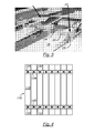
- the figure 4 is another example of facade 116 adapted to the electric heater 10.
- the facade 116 is made of modular elements 118.
- the modular elements 118 are fixed to each other by fixing bodies.
- the fixing bodies are for example in the form of two fixing bars 130, 132.
- each modular element 118 is attached to each of the two fixing bars 130, 132, for example by means of screws.
- the modular elements may comprise two centering pins 134, 136 adapted to penetrate into corresponding holes formed in the fixing bars.
- the modular elements can then be attached to the bars by means of screws. The screws can in particular be screwed into the centering pins of the modular elements.
- fastening means such as clipping or welding, as well as any removable fastening means can be implemented to fix the modular elements on the fastening bars.
- it may be provided to fix each modular element to each fixing bar by means of several screws to ensure a better rigidity of the facade and a better alignment of the modular elements forming the facade.
- the mounting bars are used to position the modular elements correctly relative to each other before attaching them to the hood. This provides a monobloc facade that can be mounted in one piece to the hood. These fixing bars can then, according to a first example, be fixed directly to the hood of the heater.
- the number of bars of the example - two - is in no way limiting.
- the same effects and benefits can be achieved with a single bar or with more than two mounting bars.
- a large number of fixing bars makes it possible to increase the rigidity of the facade formed by the fixing of the modular elements on the bars.
- the larger the facade to achieve is - that is to say the more the number of modular elements to fix is large - the more the number of fixing bars will be large.
- the modular elements can be fixed on the fixing bar or bars by clipping.
- the fixing bodies are the plate described above preventing access to the interior of the heater.
- the figure 5 schematically represents a variant of the facade 116 of the figure 4 .
- the facade 116 comprises, besides the modular elements 118 fixed together by means of at least one fastening body such as a fixing bar 130, 132, cheeks 140, 142.
- These cheeks 140, 142 complete therefore the facade 116.
- the cheeks have an aesthetic surface on the side, in a direction substantially perpendicular to the facade. The cheeks thus prevent access to the interior of the electric heater.
- the cheeks may also present, as shown on the figure 5 , a surface aesthetic forming a portion of the facade.
- the cheeks 140, 142 have a square section. In other words, these cheeks extend on the one hand in the plane of the figure 5 - that is to say the plane of the facade 116 - and, secondly, perpendicular to the plane of the figure 5 .
- the cheeks 140, 142 can be fixed to the fixing bars 130, 132, by means of fasteners identical to those used for fixing the modular elements together.
- these cheeks may be fixed to the fixing bars by any fixing means compatible with the fixing of the modular elements together.
- the cheeks 140, 142 may also be attached to the hood 14 of the electric heater.
- the cheeks 140, 142 thus allow the fixing of the facade 116 on the cover 14 of the electric heater 10.
- the fixing of the cheeks 140, 142 on the cover 14 is advantageously carried out on one or more of the folded edges 14a-14d of the cover.
- the fastening means of the cheeks on the hood are not visible on the facade 116 and therefore do not affect the aesthetics of the electric heater.
- the cheeks 140, 142 also adapt to the apparatus of the figure 2 .
- the cheeks have the same shapes and benefits as those described in connection with the figure 5 .
- the cheeks may have the same fixation bodies as those shown on the figure 3 , a fixing lug 21, 23 being provided at each end of the cheeks.
- the cheeks may have any fasteners compatible with the fixing of the modular elements to the bar.
- the fixing of the cheeks on the cover can also be performed on one or more edges of the folded edges.
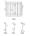
- the Figures 6-9 are examples of modular elements that can be implemented to achieve the front of the electric heater 10.
- the modular element 118 of the figure 6 has two appendages 134, 136 to allow the attachment of the modular element 118 on the fastening bars 130, 132.
- the appendices may in particular form centering pins to facilitate the relative establishment of the modular element and the bars of fixation.
- the appendices 134, 136 may comprise a tapped hole to allow the screw fixing of the modular element on the fastening bars.
- the modular element 18 of which only one side is visible on the figure 7 comprises fastening lugs 21, 23 to allow the attachment of two modular elements 18 between them, as explained above.
- the figure 8 illustrates a modular element 218 having fins 220 adapted to direct the flow of heated air by means of the convective heater 12.
- fins allow in particular to move this air flow from the wall, to prevent rapid clogging of the wall near the electrical heater.
- the fins also ensure that the interior space of the electric heater is not accessible from outside the heater.
- the fins may comprise means adapted for fixing the modular element on the hood.
- the fins can be made integrally with the modular element. However, to facilitate the manufacture of modular elements, these fins can be made separately from the modular element and be reported on the modular element posteriorly.
- these fins 222 are independent of the fixing mode of the modular elements 218 which can be between them, or on one or more fixing bars.
- the modular elements 18, 118 could also be provided with such fins 220, 222. That is to say that the various embodiments described modular elements can be combined.
- These edges extend substantially parallel to the surface forming the bottom of the hood.
- these flanges extend substantially perpendicular to the folded edge from which they are derived.
- the folded edges preferably extend towards the outside of the hood.
- each flange extends in the half-plane defined by the folded edge from which it is derived and which does not include the other folded edges of the hood.
- the edges are thus easily accessible from the side of the heater opposite the facade. Fixing the facade on these edges allows easy assembly and disassembly of the facade.
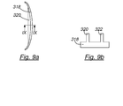
- Figures 9a, 9b illustrate an example of modular element 318 having ribs 320, 322 for reinforcing the modular element 318. These ribs prevent deformation of the modular element 318.
- the modular elements of the preceding figures may have such reinforcing ribs, combined, if necessary with the flow direction vanes of the modular element 218 of the figure 8 .
- the front of one or the other of the figures is a facade having the appearance of a heater in which a heated liquid circulates.
- This type of heater is usually referred to as an electric fluid heater.
- the slots or interstices that remain between the modular elements in the apparatus described above reproduce the aesthetic appearance of the liquid heaters.
- the modular elements described above can be planar or curved.
Landscapes
- Engineering & Computer Science (AREA)
- Physics & Mathematics (AREA)
- Thermal Sciences (AREA)
- Chemical & Material Sciences (AREA)
- Combustion & Propulsion (AREA)
- Mechanical Engineering (AREA)
- General Engineering & Computer Science (AREA)
- Central Heating Systems (AREA)
Applications Claiming Priority (1)
| Application Number | Priority Date | Filing Date | Title |
|---|---|---|---|
| FR0903841A FR2948989B1 (fr) | 2009-08-04 | 2009-08-04 | Appareil de chauffage electrique |
Publications (1)
| Publication Number | Publication Date |
|---|---|
| EP2295875A1 true EP2295875A1 (de) | 2011-03-16 |
Family
ID=42194763
Family Applications (1)
| Application Number | Title | Priority Date | Filing Date |
|---|---|---|---|
| EP10168017A Withdrawn EP2295875A1 (de) | 2009-08-04 | 2010-06-30 | Elektrisches Heizgerät |
Country Status (2)
| Country | Link |
|---|---|
| EP (1) | EP2295875A1 (de) |
| FR (1) | FR2948989B1 (de) |
Families Citing this family (1)
| Publication number | Priority date | Publication date | Assignee | Title |
|---|---|---|---|---|
| FR3082291B1 (fr) * | 2018-06-06 | 2020-07-10 | Texas De France (Sas) | Radiateur electrique comportant une facade avant composee d'elements de facade modulaires. |
Citations (9)
| Publication number | Priority date | Publication date | Assignee | Title |
|---|---|---|---|---|
| DE1928686U (de) * | 1965-08-31 | 1965-12-09 | Becker Mueller & Ulbricht O H | Kachelmantel fuer elektrisch beheizte oefen. |
| DE2062442A1 (de) * | 1970-12-18 | 1972-06-29 | Turk & Hillinger KG, 7200 Tuttlingen | Elektrisch beheizte Verkleidung für Heizgeräte od.dergl |
| AT305444B (de) * | 1970-12-07 | 1973-02-26 | Bauknecht Gmbh G | Electrisches Speicher-Heizgerät |
| FR2154009A5 (fr) * | 1971-09-16 | 1973-05-04 | Acec | Appareil de chauffage mural. |
| GB2284661A (en) * | 1993-11-04 | 1995-06-14 | Keymer Michael D | Heat emitter safety cover. |
| FR2716255A1 (fr) | 1994-02-11 | 1995-08-18 | Peyronny Bernard | Radiateur électrique à accumulation constitué d'éléments modulaires et comportant un corps de chauffe unique. |
| GB2307544A (en) * | 1995-11-24 | 1997-05-28 | Cachet Limited | Radiator cover |
| FR2885677A1 (fr) * | 2005-05-10 | 2006-11-17 | Jean Regola | Appareil de chauffage comportant une plaque de facade en matiere minerale |
| DE202009003048U1 (de) * | 2009-03-06 | 2009-06-18 | Ulamo Holding B.V. | Heizkörperblende |
-
2009
- 2009-08-04 FR FR0903841A patent/FR2948989B1/fr not_active Expired - Fee Related
-
2010
- 2010-06-30 EP EP10168017A patent/EP2295875A1/de not_active Withdrawn
Patent Citations (10)
| Publication number | Priority date | Publication date | Assignee | Title |
|---|---|---|---|---|
| DE1928686U (de) * | 1965-08-31 | 1965-12-09 | Becker Mueller & Ulbricht O H | Kachelmantel fuer elektrisch beheizte oefen. |
| AT305444B (de) * | 1970-12-07 | 1973-02-26 | Bauknecht Gmbh G | Electrisches Speicher-Heizgerät |
| DE2062442A1 (de) * | 1970-12-18 | 1972-06-29 | Turk & Hillinger KG, 7200 Tuttlingen | Elektrisch beheizte Verkleidung für Heizgeräte od.dergl |
| FR2154009A5 (fr) * | 1971-09-16 | 1973-05-04 | Acec | Appareil de chauffage mural. |
| GB2284661A (en) * | 1993-11-04 | 1995-06-14 | Keymer Michael D | Heat emitter safety cover. |
| FR2716255A1 (fr) | 1994-02-11 | 1995-08-18 | Peyronny Bernard | Radiateur électrique à accumulation constitué d'éléments modulaires et comportant un corps de chauffe unique. |
| GB2307544A (en) * | 1995-11-24 | 1997-05-28 | Cachet Limited | Radiator cover |
| FR2885677A1 (fr) * | 2005-05-10 | 2006-11-17 | Jean Regola | Appareil de chauffage comportant une plaque de facade en matiere minerale |
| DE202009003048U1 (de) * | 2009-03-06 | 2009-06-18 | Ulamo Holding B.V. | Heizkörperblende |
| EP2226573A2 (de) | 2009-03-06 | 2010-09-08 | Ulamo Holding BV | Heizkörperblende |
Also Published As
| Publication number | Publication date |
|---|---|
| FR2948989A1 (fr) | 2011-02-11 |
| FR2948989B1 (fr) | 2012-03-09 |
Similar Documents
| Publication | Publication Date | Title |
|---|---|---|
| EP2185046B1 (de) | Heisswasserbereiter für eine getränkezubereitungsmaschine | |
| EP2210049B1 (de) | Handtuchtrocknungsheizung mit einer eine zusätzliche erwärmungsvorrichtung enthaltenden wärmeträgerflüssigkeit | |
| CA3006169C (fr) | Appareil de chauffage incluant des batteries de stockage de l'energie electrique | |
| WO2009156190A1 (fr) | Chaudiere pour machine de preparation de boissons chaudes | |
| EP2295875A1 (de) | Elektrisches Heizgerät | |
| EP1030114A1 (de) | Herausnehmbare Heizbaugruppe für Elektroherd | |
| EP3125732A1 (de) | Haushaltsgerät mit einem innenraum zur aufbewahrung des stromkabels | |
| FR2800179A1 (fr) | Dispositif et procede de commande de temperature d'un recipient | |
| EP1266592B1 (de) | Fertigmontagesatz für Einbaubareelemente eines Haushaltgeräts in einer Nische | |
| WO2016128397A1 (fr) | Dispositif de chauffage electrique et conduit de circulation d'air dans une installation de ventilation, chauffage et/ou climatisation | |
| EP1266593B1 (de) | Kippsichere Vorrichtung für ein einbaubares Haushaltsgerät in eine Nische | |
| FR2526932A1 (fr) | Echangeur de chaleur tel que radiateur de vehicule automobile | |
| EP3299733A1 (de) | Thermischer körper für sockelvorichtung oder thermische schwelle, und sockelvorrichtung oder thermische schwelle, die mit mindestens einem solchen thermischen körper ausgerüstet ist | |
| EP1967797A1 (de) | Heizgerät mit verbundenem Luftauslass | |
| FR3100602A1 (fr) | Ensemble de décoration pour radiateur et procédé d’installation associé | |
| FR3082291A1 (fr) | Radiateur electrique comportant une facade avant composee d'elements de facade modulaires. | |
| EP4050271B1 (de) | Heizgerät mit mindestens einer vertikalen heizsäule, an der trockenstäbe angebracht sind | |
| FR3062895A1 (fr) | Dispositif de chauffage electrique domestique, en particulier du type seche-serviettes. | |
| FR2864845A1 (fr) | Radiateur electrique et plaque reflecteur associee, ainsi que procede de transformation d'un radiateur a convection en un radiateur a accumulation | |
| FR2850737A1 (fr) | Appareil de chauffage electrique mobile, a effet de rayonnement et de convection | |
| FR2851405A1 (fr) | Element chauffant et grille-pain electrique a isolation thermique | |
| FR2980099A1 (fr) | Cartouche de lampe a decharge pour une poignee d'un appareil de phototraitement | |
| FR2978503A1 (fr) | Appareil transformant l'energie eolienne en energie electrique | |
| WO2015144876A1 (fr) | Boitier d'ordinateur et ordinateur comportant un tel boitier | |
| FR3145797A1 (fr) | Corps de chauffe à inertie pour radiateur électrique |
Legal Events
| Date | Code | Title | Description |
|---|---|---|---|
| PUAI | Public reference made under article 153(3) epc to a published international application that has entered the european phase |
Free format text: ORIGINAL CODE: 0009012 |
|
| AK | Designated contracting states |
Kind code of ref document: A1 Designated state(s): AL AT BE BG CH CY CZ DE DK EE ES FI FR GB GR HR HU IE IS IT LI LT LU LV MC MK MT NL NO PL PT RO SE SI SK SM TR |
|
| AX | Request for extension of the european patent |
Extension state: BA ME RS |
|
| 17P | Request for examination filed |
Effective date: 20110916 |
|
| TPAC | Observations filed by third parties |
Free format text: ORIGINAL CODE: EPIDOSNTIPA |
|
| 17Q | First examination report despatched |
Effective date: 20140206 |
|
| TPAC | Observations filed by third parties |
Free format text: ORIGINAL CODE: EPIDOSNTIPA |
|
| STAA | Information on the status of an ep patent application or granted ep patent |
Free format text: STATUS: THE APPLICATION IS DEEMED TO BE WITHDRAWN |
|
| 18D | Application deemed to be withdrawn |
Effective date: 20161124 |