EP2295864B1 - Dispositif de combustion de turbine à gaz - Google Patents
Dispositif de combustion de turbine à gaz Download PDFInfo
- Publication number
- EP2295864B1 EP2295864B1 EP09169091A EP09169091A EP2295864B1 EP 2295864 B1 EP2295864 B1 EP 2295864B1 EP 09169091 A EP09169091 A EP 09169091A EP 09169091 A EP09169091 A EP 09169091A EP 2295864 B1 EP2295864 B1 EP 2295864B1
- Authority
- EP
- European Patent Office
- Prior art keywords
- combustion device
- plate
- chambers
- passages
- wall
- Prior art date
- Legal status (The legal status is an assumption and is not a legal conclusion. Google has not performed a legal analysis and makes no representation as to the accuracy of the status listed.)
- Active
Links
- 238000002485 combustion reaction Methods 0.000 title claims description 88
- 239000007789 gas Substances 0.000 description 16
- 230000010349 pulsation Effects 0.000 description 13
- 238000013016 damping Methods 0.000 description 8
- 230000037406 food intake Effects 0.000 description 7
- 238000001816 cooling Methods 0.000 description 4
- 125000006850 spacer group Chemical group 0.000 description 4
- 239000000567 combustion gas Substances 0.000 description 3
- 230000000694 effects Effects 0.000 description 3
- 239000000446 fuel Substances 0.000 description 3
- 238000005553 drilling Methods 0.000 description 2
- 239000000203 mixture Substances 0.000 description 2
- XLYOFNOQVPJJNP-UHFFFAOYSA-N water Substances O XLYOFNOQVPJJNP-UHFFFAOYSA-N 0.000 description 2
- 238000005219 brazing Methods 0.000 description 1
- 238000004519 manufacturing process Methods 0.000 description 1
- 239000000463 material Substances 0.000 description 1
- 238000003801 milling Methods 0.000 description 1
- 230000004048 modification Effects 0.000 description 1
- 238000012986 modification Methods 0.000 description 1
- 238000011144 upstream manufacturing Methods 0.000 description 1
Images
Classifications
-
- F—MECHANICAL ENGINEERING; LIGHTING; HEATING; WEAPONS; BLASTING
- F23—COMBUSTION APPARATUS; COMBUSTION PROCESSES
- F23R—GENERATING COMBUSTION PRODUCTS OF HIGH PRESSURE OR HIGH VELOCITY, e.g. GAS-TURBINE COMBUSTION CHAMBERS
- F23R3/00—Continuous combustion chambers using liquid or gaseous fuel
- F23R3/002—Wall structures
-
- F—MECHANICAL ENGINEERING; LIGHTING; HEATING; WEAPONS; BLASTING
- F23—COMBUSTION APPARATUS; COMBUSTION PROCESSES
- F23M—CASINGS, LININGS, WALLS OR DOORS SPECIALLY ADAPTED FOR COMBUSTION CHAMBERS, e.g. FIREBRIDGES; DEVICES FOR DEFLECTING AIR, FLAMES OR COMBUSTION PRODUCTS IN COMBUSTION CHAMBERS; SAFETY ARRANGEMENTS SPECIALLY ADAPTED FOR COMBUSTION APPARATUS; DETAILS OF COMBUSTION CHAMBERS, NOT OTHERWISE PROVIDED FOR
- F23M20/00—Details of combustion chambers, not otherwise provided for, e.g. means for storing heat from flames
- F23M20/005—Noise absorbing means
-
- F—MECHANICAL ENGINEERING; LIGHTING; HEATING; WEAPONS; BLASTING
- F23—COMBUSTION APPARATUS; COMBUSTION PROCESSES
- F23R—GENERATING COMBUSTION PRODUCTS OF HIGH PRESSURE OR HIGH VELOCITY, e.g. GAS-TURBINE COMBUSTION CHAMBERS
- F23R2900/00—Special features of, or arrangements for continuous combustion chambers; Combustion processes therefor
- F23R2900/00014—Reducing thermo-acoustic vibrations by passive means, e.g. by Helmholtz resonators
Definitions
- the present invention relates to a combustion device of a gas turbine.
- the present invention refers to a damping system of a combustion device.
- the combustion device may be the first and/or the second combustion device of a sequential combustion gas turbine or a combustion device of a traditional gas turbine (i.e. a gas turbine not being a sequential combustion gas turbine).
- reheat combustion device i.e. the second combustion device of a sequential combustion gas turbine
- thermo acoustic (i.e. pressure) pulsations can occur in the combustion chamber, because of an incorrect combustion of the fuel (such as gas or oil).
- combustion devices are usually provided with dampers, such as the Helmholtz dampers.
- Helmholtz dampers consist of a resonance chamber that is connected via a damping tube to the interior of the combustion chamber (or the medium surrounding the combustion chamber).
- Usual reheat combustion devices have one Helmholtz damper with the tube connected to the inner of the combustion chamber.
- US2005/0229581 discloses a reheat combustion device that has a mixing tube followed by a combustion chamber; the mixing tube has at its front panel an acoustic screen provided with holes and, parallel to it, an impingement plate also provided with holes.
- the acoustic screen and the impingement plate define a chamber connected to the inner of the combustion chamber (via the holes of the acoustic screen) and to the outer of the combustion chamber (via the holes of the impingement plate).
- air (from the compressor) passes through the holes of the impingement plate, impinges on the acoustic screen and then enters the combustion chamber; this lets the acoustic screen and the impingement plate be cooled.
- the chamber between the impingement plate and acoustic screen defines a plurality of Helmholtz dampers such that, since a plurality of dampers are associated to each reheat combustion device, the damping effect is improved.
- hot gases may enter from the combustion chamber into the chamber between the impingement plate and the acoustic screen and go out again, coming back into the combustion chamber.
- the hot air flow that recirculates makes the acoustic screen and impingement plate to burn in a very short time.
- a further drawback of ingestion is that of detuning of the acoustic damper.
- the cooling efficiency is not optimised; this makes different parts of the combustion chamber to be cooled in different way and to operate at different temperatures.
- EP 0 892 216 discloses a combustion device with a first and a second wall with first passages connecting the zone between the walls to the inside of the combustion device and second passages connecting the zone between the walls to the outside of the combustion device.
- EP 0 892 216 also discloses plates between the first and second walls to define chambers (honeycomb structure) that are connected to the first and second passages.
- the technical aim of the present invention is therefore to provide a combustion device by which the said problems of the known art are eliminated.
- an object of the invention is to provide a combustion device that is reliable and in particular has no ingestion problems.
- Another object of the invention is to provide a combustion device that is not subjected to detuning of the acoustic damper.
- Another object of the invention is to provide a combustion device that has a good cooling efficiency, such that the temperature of the combustion chamber is more uniform than in traditional combustion devices.
- a compressor followed by a first combustion chamber and a high pressure turbine are provided (not shown).
- the hot gases are fed into the reheat combustion device 1, wherein fuel is injected to be combusted; thus a low pressure turbine expands the combusted flow coming from the reheat combustion device 1.
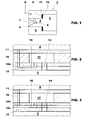
- the reheat combustion device 1 comprises a mixing tube 2 and a combustion chamber 3 inserted in a plenum 4 wherein air A from the compressor is fed.
- the mixing tube 2 is arranged to be fed with the hot gases through an inlet 6 and is provided with vortex generators 7 (usually four vortex generators extending from the four walls of the mixing tube, for sake of clarity only one of the four vortex generators is shown in figure 1 ) and a lance that has nozzles 8 for injecting fuel within the hot gases and generate the mixture.
- vortex generators 7 usually four vortex generators extending from the four walls of the mixing tube, for sake of clarity only one of the four vortex generators is shown in figure 1
- a lance that has nozzles 8 for injecting fuel within the hot gases and generate the mixture.
- the device 1 Downstream of the mixing tube 2, the device 1 has the combustion chamber 3 arranged to be fed with the mixture and burn it.
- the combustion device 1 comprises a portion 9 provided with a first and a second wall 11, 12 provided with first passages 14 connecting the zone between the first and second wall 11, 12 to the inner of the combustion device 1 and second passages 15 connecting said zone between the first and second wall 11, 12 to the outer of the combustion device 1.
- portion 9 is described as the portion at the front panel of the mixing tube, it is anyhow clear that the portion 9 can be located in any position of the mixing tube 2 and/or combustion chamber 3.
- each chamber 17 being connected with one first passage 14 and one (or also more than one) second passages 15 and defining a Helmholtz damper.
- the chambers 17 are defined by one (or in a different embodiment more than one) first plate 16 interposed between the first and second wall 11, 12.
- the chambers 17 are defined by holes indented in the first plate 16.
- the holes defining the chambers 17 can be through holes ( figures 2 and 3 ).
- the combustion device 1 may also comprise a second plate 16b laying side-by-side with the first plate 16, defining at least a side of the chamber 17 and also defining the first and/or second passages 14, 15 ( figures 2 and 3 ).
- combustion device may also comprise a third plate 16c coupled to the second plate 16b and also defining the first and/or second passages 14, 15 ( figures 3 ).
- the second plate 16b has through holes and the third plate 16c has through slots connected one another.
- the holes defining the chambers 17 are blind holes of the first plate 16 ( figure 5 ).
- the combustion device has a plurality of first plates 16 defining a spacer grid interposed between the first and second walls 14, 15 to define the chambers 17 ( figures 6 ).
- the chambers 17 are defined by blind holes indented in the first and/or second wall 11, 12 ( figure 4 ).
- a plate 16 defining a side of the chamber 17 may be provided or also no plate may be provided, such that the walls 11,12 are directly coupled one another.
- the second passages 15 open at the same side of the chambers 17 as the first passages 14 and each chamber 17 is connected to one single first passage 14 and one single second passage 15.
- each gas turbine has a plurality of combustion device placed side-by-side.
- all the chambers 17 and first passages 14 of a single combustion device 1 have the same dimensions that are different from those of the other combustion devices 1 of the same gas turbine; in different embodiments of the invention, the chambers 17 of a single combustion device 1 have different dimensions. This lets different acoustic pulsations be damped very efficiently in a very wide acoustic pulsation band.
- the first plate 16 is the front panel at the exit of the mixing tube 2 (i.e. this wall is manufactured in one piece with the mixing tube).
- passages 14, 15 and chambers 17 are indented by drilling, laser cut, water jet, milling and so on.
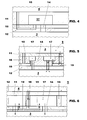
- Figure 2 shows an embodiment of the invention with first wall 11 and second wall 12 enclosing the first plate 16 and the second plate 16b connected side-by-side therewith.
- the chambers 17 are defined by through holes indented in the first plate 16; moreover the sides of the chambers 17 are defined by the first wall 11 (the side towards the plenum 4) and the second plate 16b (the side connected towards the combustion chamber 3).
- the first passage 14 connecting the inner of the chambers 17 to the combustion chamber 3 is drilled in the second wall 12 and second plate 16b.
- the second passage 15 comprises a portion drilled in the second plate 16b and opening in the chamber 17, and a further portion milled in the second wall 12, and further portions drilled in the second plate 16b, in the first plate 16 and in the first wall 11 opening in the plane 4.
- Figure 3 shows a further embodiment of the invention with the third plate 16c connected to the second plate 16b.
- the chambers 17 are defined by through holes of the first plate 16 delimited by the first wall 11 and second plate 16b.
- the first passages 14 are drilled in the second and third plates 16b, 16c and in the second wall 12.
- the second passage 15 has two spaced apart portions drilled in the second plate 16b and a portion drilled in the third plate 16c, connecting the before mentioned spaced apart portions drilled in the second plate 16b.
- the second passage 15 also has portions drilled in the first plate 16 and first wall 11.
- This embodiment is particularly advantageous, because the chambers 17, and the first and second passages 14, 15 are defined by through holes and can be manufactured in an easy and fast way for example by drilling, laser cut, water jet and so on.
- Figure 4 shows an embodiment not covered by the invention with the chamber indented in the first wall 11 and also defined by a plate 16 that delimits it.
- the first passage 14 is drilled in the plate 16 and second wall 12.
- the second passage 15 has two spaced apart portions drilled in the plate 16 and connected each other by a portion milled in the second wall; it also has a portion drilled in the first wall 11.
- Figure 5 shows an embodiment with chambers 17 defined by blind holes indented in the first plate 16; the first wall 11 defines the side towards the plenum 4 of the chambers 17.
- the first passages 14 are drilled in the first plate 16 and second wall 12 and the second passages 15 are drilled and milled in the first plate 16 and are also drilled in the first wall 11; in particular reference 19 indicates the part of the second passage 15 milled in the plate 16.
- Figure 6 shows a further embodiment not covered by the invention with the first and second walls 11, 12 enclosing a spacer grid made of plates 16 placed at square angle with each other to define a plurality of quadrangular chambers 17.
- the first passages 14 are drilled in the second wall 12 and the first passages 15 are drilled and milled in the second wall 12 and also have a portion drilled in the spacer (preferably at the intersection between the plates) and in the first wall 11; reference 19 indicates the part of the second passages 15 milled in the second wall 12 and then covered by a further outer plate.
- Air A from the compressor enters the plenum 4 and, thus, through the second passages 15 enters the chambers 17.
- Each chamber 17 with the first passages 14 constitutes a Helmholtz damper that lets the acoustic pulsations be damped.
- each chamber 17 The volume of each chamber 17, the length of each first passage 14 and the area of the cross section of each first passage 14 can be selected such that the Helmholtz damper that they define damps acoustic pulsation (i.e. pressure pulsation) in a particular band.
- the combustion device of the invention is able to damp acoustic pulsations in a very broad band, since in first embodiments each device is provided with chambers/first passages having fixed dimensions that are different from the dimension of the other devices, and in second embodiments each device has chambers/first passages of different dimensions.
- the area of the cross section of the second passages 15 can be selected such that the air passing through them lets a uniform cooling be achieved in the first wall 11, second wall 12 and plates 16, 16b, 16c.
- hot gas ingestion is not critical, because ingestion (i.e. recirculation of the hot gases from the combustion chamber 3 to the chamber 17 and back to the combustion chamber 3) cannot occur, since each chamber 17 only has one single first passage 14 connecting it to the combustion chamber 3.
Landscapes
- Engineering & Computer Science (AREA)
- Chemical & Material Sciences (AREA)
- Combustion & Propulsion (AREA)
- Mechanical Engineering (AREA)
- General Engineering & Computer Science (AREA)
- Turbine Rotor Nozzle Sealing (AREA)
Claims (11)
- Dispositif de combustion (1) pour une turbine à gaz, comprenant une partie (9) pourvue de première et deuxième parois (11, 12) pourvues de premiers passages (14) reliant la zone située entre les première et deuxième parois (11, 12) à l'intérieur du dispositif de combustion (1) et de deuxièmes passages (15) reliant ladite zone située entre les première et deuxième parois (11, 12) à l'extérieur du dispositif de combustion (1), une pluralité de chambres (17) étant définies entre les première et deuxième parois (11, 12), chacune étant reliée à un premier passage (14) et à au moins un deuxième passage (15), et définissant un absorbeur de Helmholtz,
lesquelles chambres (17) sont définies par au moins une première plaque (16) intercalée entre les première et deuxième parois (11, 12),
le dispositif de combustion (1) étant caractérisé en ce que les chambres (17) sont définies par des trous ménagés dans ladite première plaque. - Dispositif de combustion (1) selon la revendication 1, caractérisé en ce que lesdits trous définissant les chambres (17) sont des trous traversants.
- Dispositif de combustion (1) selon la revendication 2, caractérisé en ce qu'il comprend au moins une deuxième plaque (16b) définissant au moins un côté des chambres (17) et définissant également lesdits premiers et/ou deuxièmes passages (14, 15).
- Dispositif de combustion (1) selon la revendication 3, caractérisé en ce qu'il comprend en outre une troisième plaque (16c) accouplée à ladite deuxième plaque (16b) et définissant également lesdits premiers et/ou deuxièmes passages (14, 15).
- Dispositif de combustion (1) selon la revendication 4, caractérisé en ce que, de façon à définir au moins lesdits deuxièmes passages (15), la deuxième plaque (16b) comprend des trous traversants et la troisième plaque (16c) comprend des fentes traversantes.
- Dispositif de combustion (1) selon la revendication 1, caractérisé en ce que lesdits trous définissant les chambres (17) sont des trous borgnes.
- Dispositif de combustion (1) selon la revendication 1, caractérisé en ce que lesdits deuxièmes passages (15) débouchent du même côté desdites chambres (17) que les premiers passages (14).
- Dispositif de combustion (1) selon la revendication 1, caractérisé en ce que les chambres (17) d'un même dispositif de combustion (1) présentent les mêmes dimensions.
- Dispositif de combustion (1) selon la revendication 1, caractérisé en ce que les chambres (17) d'un même dispositif de combustion (1) présentent des dimensions différentes.
- Dispositif de combustion (1) selon la revendication 1, caractérisé en ce qu'il s'agit d'un dispositif de postcombustion et en ce qu'il comprend un tube mélangeur (2) pourvu de buses (8) et, en aval dudit tube mélangeur (2), une chambre de combustion (3) agencée de manière à être alimentée par le tube mélangeur, ladite partie (9) étant une partie du tube mélangeur et/ou une partie de la chambre de combustion.
- Dispositif de combustion (1) selon la revendication 1, caractérisé en ce que chaque chambre (17) est reliée à un seul deuxième passage (15).
Priority Applications (4)
| Application Number | Priority Date | Filing Date | Title |
|---|---|---|---|
| EP09169091A EP2295864B1 (fr) | 2009-08-31 | 2009-08-31 | Dispositif de combustion de turbine à gaz |
| ES09169091T ES2400267T3 (es) | 2009-08-31 | 2009-08-31 | Dispositivo de combustión de una turbina de gas |
| US12/871,310 US8839624B2 (en) | 2009-08-31 | 2010-08-30 | Combustion device of a gas turbine including a plurality of passages and chambers defining helmholtz resonators |
| JP2010191725A JP5631121B2 (ja) | 2009-08-31 | 2010-08-30 | ガスタービンの燃焼装置 |
Applications Claiming Priority (1)
| Application Number | Priority Date | Filing Date | Title |
|---|---|---|---|
| EP09169091A EP2295864B1 (fr) | 2009-08-31 | 2009-08-31 | Dispositif de combustion de turbine à gaz |
Publications (2)
| Publication Number | Publication Date |
|---|---|
| EP2295864A1 EP2295864A1 (fr) | 2011-03-16 |
| EP2295864B1 true EP2295864B1 (fr) | 2012-11-14 |
Family
ID=41506488
Family Applications (1)
| Application Number | Title | Priority Date | Filing Date |
|---|---|---|---|
| EP09169091A Active EP2295864B1 (fr) | 2009-08-31 | 2009-08-31 | Dispositif de combustion de turbine à gaz |
Country Status (4)
| Country | Link |
|---|---|
| US (1) | US8839624B2 (fr) |
| EP (1) | EP2295864B1 (fr) |
| JP (1) | JP5631121B2 (fr) |
| ES (1) | ES2400267T3 (fr) |
Cited By (1)
| Publication number | Priority date | Publication date | Assignee | Title |
|---|---|---|---|---|
| EP2837782A1 (fr) | 2013-08-14 | 2015-02-18 | Alstom Technology Ltd | Dispositif d'amortissement d'oscillation de combustion dans une turbine à gaz |
Families Citing this family (22)
| Publication number | Priority date | Publication date | Assignee | Title |
|---|---|---|---|---|
| EP2295864B1 (fr) * | 2009-08-31 | 2012-11-14 | Alstom Technology Ltd | Dispositif de combustion de turbine à gaz |
| EP2362147B1 (fr) * | 2010-02-22 | 2012-12-26 | Alstom Technology Ltd | Dispositif de combustion pour turbine à gaz |
| EP2385303A1 (fr) | 2010-05-03 | 2011-11-09 | Alstom Technology Ltd | Dispositif de combustion pour turbine à gaz |
| US9127837B2 (en) * | 2010-06-22 | 2015-09-08 | Carrier Corporation | Low pressure drop, low NOx, induced draft gas heaters |
| KR101671600B1 (ko) * | 2012-02-24 | 2016-11-16 | 미츠비시 쥬고교 가부시키가이샤 | 음향 댐퍼, 연소기 및 가스 터빈 |
| US20130255260A1 (en) * | 2012-03-29 | 2013-10-03 | Solar Turbines Inc. | Resonance damper for damping acoustic oscillations from combustor |
| US20130283799A1 (en) * | 2012-04-25 | 2013-10-31 | Solar Turbines Inc. | Resonance damper for damping acoustic oscillations from combustor |
| EP2685170A1 (fr) | 2012-07-10 | 2014-01-15 | Alstom Technology Ltd | Structure de paroi refroidie pour les parties chaudes d'une turbine à gaz et procédé de fabrication d'une telle structure |
| EP2693121B1 (fr) | 2012-07-31 | 2018-04-25 | Ansaldo Energia Switzerland AG | Rugosité proche de la paroi pour dispositifs d'amortissement réduisant les oscillations de pression dans les systèmes de combustion |
| EP2735796B1 (fr) | 2012-11-23 | 2020-01-01 | Ansaldo Energia IP UK Limited | Paroi située sur la trajectoire des gaz chauds d'une turbine à gaz et procédé pour améliorer le comportement de fonctionnment d'une turbine à gaz |
| EP2738469B1 (fr) | 2012-11-30 | 2019-04-17 | Ansaldo Energia IP UK Limited | Pièce de chambre de combustion de turbine à gaz comprenant un agencement de refroidissement de paroi |
| EP2762784B1 (fr) * | 2012-11-30 | 2016-02-03 | Alstom Technology Ltd | Dispositif d'amortissement pour chambre de combustion de turbine à gaz |
| EP3029377B1 (fr) * | 2014-12-03 | 2018-04-11 | Ansaldo Energia Switzerland AG | Amortisseur pour une turbine à gaz |
| US10094571B2 (en) | 2014-12-11 | 2018-10-09 | General Electric Company | Injector apparatus with reheat combustor and turbomachine |
| US10094569B2 (en) | 2014-12-11 | 2018-10-09 | General Electric Company | Injecting apparatus with reheat combustor and turbomachine |
| US10107498B2 (en) | 2014-12-11 | 2018-10-23 | General Electric Company | Injection systems for fuel and gas |
| US10094570B2 (en) | 2014-12-11 | 2018-10-09 | General Electric Company | Injector apparatus and reheat combustor |
| EP3048370A1 (fr) | 2015-01-23 | 2016-07-27 | Siemens Aktiengesellschaft | Chambre de combustion pour un moteur de turbine à gaz |
| US10513984B2 (en) | 2015-08-25 | 2019-12-24 | General Electric Company | System for suppressing acoustic noise within a gas turbine combustor |
| US11174792B2 (en) * | 2019-05-21 | 2021-11-16 | General Electric Company | System and method for high frequency acoustic dampers with baffles |
| US11852343B2 (en) * | 2019-12-24 | 2023-12-26 | Mitsubishi Heavy Industries, Ltd. | Combustor component, combustor including the combustor component, and gas turbine including the combustor |
| CN117109030A (zh) * | 2022-05-16 | 2023-11-24 | 通用电气公司 | 燃烧器衬里中的热声阻尼器 |
Family Cites Families (26)
| Publication number | Priority date | Publication date | Assignee | Title |
|---|---|---|---|---|
| DE59208715D1 (de) * | 1992-11-09 | 1997-08-21 | Asea Brown Boveri | Gasturbinen-Brennkammer |
| US5644918A (en) * | 1994-11-14 | 1997-07-08 | General Electric Company | Dynamics free low emissions gas turbine combustor |
| DE19640980B4 (de) * | 1996-10-04 | 2008-06-19 | Alstom | Vorrichtung zur Dämpfung von thermoakustischen Schwingungen in einer Brennkammer |
| EP0892216B1 (fr) * | 1997-07-15 | 2003-02-05 | ALSTOM (Switzerland) Ltd | Structure de paroi de chambre de combustion absorbant les vibrations |
| EP0990851B1 (fr) * | 1998-09-30 | 2003-07-23 | ALSTOM (Switzerland) Ltd | Chambre de combustion pour une turbine à gaz |
| US6351947B1 (en) * | 2000-04-04 | 2002-03-05 | Abb Alstom Power (Schweiz) | Combustion chamber for a gas turbine |
| US6530221B1 (en) * | 2000-09-21 | 2003-03-11 | Siemens Westinghouse Power Corporation | Modular resonators for suppressing combustion instabilities in gas turbine power plants |
| GB2390150A (en) | 2002-06-26 | 2003-12-31 | Alstom | Reheat combustion system for a gas turbine including an accoustic screen |
| WO2004051063A1 (fr) * | 2002-12-02 | 2004-06-17 | Mitsubishi Heavy Industries, Ltd. | Chambre de combustion de turbine a gaz et turbine a gaz equipee de cette chambre de combustion |
| GB2396687A (en) * | 2002-12-23 | 2004-06-30 | Rolls Royce Plc | Helmholtz resonator for combustion chamber use |
| US7080514B2 (en) * | 2003-08-15 | 2006-07-25 | Siemens Power Generation,Inc. | High frequency dynamics resonator assembly |
| JP2005076982A (ja) * | 2003-08-29 | 2005-03-24 | Mitsubishi Heavy Ind Ltd | ガスタービン燃焼器 |
| ITTO20031013A1 (it) * | 2003-12-16 | 2005-06-17 | Ansaldo Energia Spa | Sistema di smorzamento di instabilita' termoacustiche in un dispositivo combustore per una turbina a gas. |
| US7337875B2 (en) * | 2004-06-28 | 2008-03-04 | United Technologies Corporation | High admittance acoustic liner |
| US7334408B2 (en) * | 2004-09-21 | 2008-02-26 | Siemens Aktiengesellschaft | Combustion chamber for a gas turbine with at least two resonator devices |
| GB0425794D0 (en) * | 2004-11-24 | 2004-12-22 | Rolls Royce Plc | Acoustic damper |
| GB0427147D0 (en) * | 2004-12-11 | 2005-01-12 | Rolls Royce Plc | Combustion chamber for a gas turbine engine |
| US7461719B2 (en) * | 2005-11-10 | 2008-12-09 | Siemens Energy, Inc. | Resonator performance by local reduction of component thickness |
| GB0610800D0 (en) * | 2006-06-01 | 2006-07-12 | Rolls Royce Plc | Combustion chamber for a gas turbine engine |
| US7788926B2 (en) * | 2006-08-18 | 2010-09-07 | Siemens Energy, Inc. | Resonator device at junction of combustor and combustion chamber |
| JP2009062977A (ja) * | 2007-08-15 | 2009-03-26 | Rohr Inc | 線形音響ライナー |
| US8061141B2 (en) * | 2007-09-27 | 2011-11-22 | Siemens Energy, Inc. | Combustor assembly including one or more resonator assemblies and process for forming same |
| US20100236245A1 (en) * | 2009-03-19 | 2010-09-23 | Johnson Clifford E | Gas Turbine Combustion System |
| EP2295864B1 (fr) * | 2009-08-31 | 2012-11-14 | Alstom Technology Ltd | Dispositif de combustion de turbine à gaz |
| EP2362147B1 (fr) * | 2010-02-22 | 2012-12-26 | Alstom Technology Ltd | Dispositif de combustion pour turbine à gaz |
| EP2385303A1 (fr) * | 2010-05-03 | 2011-11-09 | Alstom Technology Ltd | Dispositif de combustion pour turbine à gaz |
-
2009
- 2009-08-31 EP EP09169091A patent/EP2295864B1/fr active Active
- 2009-08-31 ES ES09169091T patent/ES2400267T3/es active Active
-
2010
- 2010-08-30 US US12/871,310 patent/US8839624B2/en not_active Expired - Fee Related
- 2010-08-30 JP JP2010191725A patent/JP5631121B2/ja not_active Expired - Fee Related
Cited By (2)
| Publication number | Priority date | Publication date | Assignee | Title |
|---|---|---|---|---|
| EP2837782A1 (fr) | 2013-08-14 | 2015-02-18 | Alstom Technology Ltd | Dispositif d'amortissement d'oscillation de combustion dans une turbine à gaz |
| EP2837783A1 (fr) | 2013-08-14 | 2015-02-18 | Alstom Technology Ltd | Dispositif d'amortissement d'oscillation de combustion dans une turbine à gaz |
Also Published As
| Publication number | Publication date |
|---|---|
| ES2400267T3 (es) | 2013-04-08 |
| US8839624B2 (en) | 2014-09-23 |
| JP2011052955A (ja) | 2011-03-17 |
| US20110048018A1 (en) | 2011-03-03 |
| JP5631121B2 (ja) | 2014-11-26 |
| EP2295864A1 (fr) | 2011-03-16 |
Similar Documents
| Publication | Publication Date | Title |
|---|---|---|
| EP2295864B1 (fr) | Dispositif de combustion de turbine à gaz | |
| EP2385303A1 (fr) | Dispositif de combustion pour turbine à gaz | |
| EP2362147B1 (fr) | Dispositif de combustion pour turbine à gaz | |
| JP5730379B2 (ja) | ガスタービン燃焼器用の減衰装置 | |
| US7549290B2 (en) | Acoustic damper | |
| US6981358B2 (en) | Reheat combustion system for a gas turbine | |
| CA2551539C (fr) | Chambre de combustion de turbine a gaz a refroidissement ameliore | |
| EP2693121B1 (fr) | Rugosité proche de la paroi pour dispositifs d'amortissement réduisant les oscillations de pression dans les systèmes de combustion | |
| JP2008256351A (ja) | 燃焼器ダイナミクスを低減するためのシステム | |
| EP2116770B1 (fr) | Atténuation dynamique de chambre de combustion et agencement de refroidissement | |
| KR20150044820A (ko) | 연소기 냉각 구조 | |
| EP2725198B1 (fr) | Transition de chambre de combustion | |
| JP2016121689A (ja) | 希釈用空気噴射部を有する軸方向段階混合器 | |
| JP6148504B2 (ja) | マイクロミキサ内の燃焼器ダイナミックスを減衰させるためのシステムおよび方法 | |
| CN103765105A (zh) | 用于燃气轮机设备的燃烧室 | |
| US7065971B2 (en) | Device for efficient usage of cooling air for acoustic damping of combustion chamber pulsations | |
| EP2955443A1 (fr) | Agencement de paroi refroidi par impact | |
| JP5357631B2 (ja) | 燃料ノズル、これを備えた燃焼器及びガスタービン |
Legal Events
| Date | Code | Title | Description |
|---|---|---|---|
| PUAI | Public reference made under article 153(3) epc to a published international application that has entered the european phase |
Free format text: ORIGINAL CODE: 0009012 |
|
| AK | Designated contracting states |
Kind code of ref document: A1 Designated state(s): AT BE BG CH CY CZ DE DK EE ES FI FR GB GR HR HU IE IS IT LI LT LU LV MC MK MT NL NO PL PT RO SE SI SK SM TR |
|
| 17P | Request for examination filed |
Effective date: 20110829 |
|
| 17Q | First examination report despatched |
Effective date: 20111118 |
|
| GRAP | Despatch of communication of intention to grant a patent |
Free format text: ORIGINAL CODE: EPIDOSNIGR1 |
|
| GRAS | Grant fee paid |
Free format text: ORIGINAL CODE: EPIDOSNIGR3 |
|
| GRAA | (expected) grant |
Free format text: ORIGINAL CODE: 0009210 |
|
| AK | Designated contracting states |
Kind code of ref document: B1 Designated state(s): AT BE BG CH CY CZ DE DK EE ES FI FR GB GR HR HU IE IS IT LI LT LU LV MC MK MT NL NO PL PT RO SE SI SK SM TR |
|
| REG | Reference to a national code |
Ref country code: GB Ref legal event code: FG4D |
|
| REG | Reference to a national code |
Ref country code: CH Ref legal event code: EP Ref country code: AT Ref legal event code: REF Ref document number: 584210 Country of ref document: AT Kind code of ref document: T Effective date: 20121115 |
|
| REG | Reference to a national code |
Ref country code: IE Ref legal event code: FG4D |
|
| REG | Reference to a national code |
Ref country code: DE Ref legal event code: R096 Ref document number: 602009011143 Country of ref document: DE Effective date: 20130110 |
|
| REG | Reference to a national code |
Ref country code: ES Ref legal event code: FG2A Ref document number: 2400267 Country of ref document: ES Kind code of ref document: T3 Effective date: 20130408 |
|
| REG | Reference to a national code |
Ref country code: NL Ref legal event code: VDEP Effective date: 20121114 |
|
| REG | Reference to a national code |
Ref country code: AT Ref legal event code: MK05 Ref document number: 584210 Country of ref document: AT Kind code of ref document: T Effective date: 20121114 |
|
| REG | Reference to a national code |
Ref country code: LT Ref legal event code: MG4D |
|
| PG25 | Lapsed in a contracting state [announced via postgrant information from national office to epo] |
Ref country code: NO Free format text: LAPSE BECAUSE OF FAILURE TO SUBMIT A TRANSLATION OF THE DESCRIPTION OR TO PAY THE FEE WITHIN THE PRESCRIBED TIME-LIMIT Effective date: 20130214 Ref country code: LT Free format text: LAPSE BECAUSE OF FAILURE TO SUBMIT A TRANSLATION OF THE DESCRIPTION OR TO PAY THE FEE WITHIN THE PRESCRIBED TIME-LIMIT Effective date: 20121114 Ref country code: FI Free format text: LAPSE BECAUSE OF FAILURE TO SUBMIT A TRANSLATION OF THE DESCRIPTION OR TO PAY THE FEE WITHIN THE PRESCRIBED TIME-LIMIT Effective date: 20121114 Ref country code: HR Free format text: LAPSE BECAUSE OF FAILURE TO SUBMIT A TRANSLATION OF THE DESCRIPTION OR TO PAY THE FEE WITHIN THE PRESCRIBED TIME-LIMIT Effective date: 20121114 Ref country code: SE Free format text: LAPSE BECAUSE OF FAILURE TO SUBMIT A TRANSLATION OF THE DESCRIPTION OR TO PAY THE FEE WITHIN THE PRESCRIBED TIME-LIMIT Effective date: 20121114 |
|
| PG25 | Lapsed in a contracting state [announced via postgrant information from national office to epo] |
Ref country code: PT Free format text: LAPSE BECAUSE OF FAILURE TO SUBMIT A TRANSLATION OF THE DESCRIPTION OR TO PAY THE FEE WITHIN THE PRESCRIBED TIME-LIMIT Effective date: 20130314 Ref country code: PL Free format text: LAPSE BECAUSE OF FAILURE TO SUBMIT A TRANSLATION OF THE DESCRIPTION OR TO PAY THE FEE WITHIN THE PRESCRIBED TIME-LIMIT Effective date: 20121114 Ref country code: BE Free format text: LAPSE BECAUSE OF FAILURE TO SUBMIT A TRANSLATION OF THE DESCRIPTION OR TO PAY THE FEE WITHIN THE PRESCRIBED TIME-LIMIT Effective date: 20121114 Ref country code: SI Free format text: LAPSE BECAUSE OF FAILURE TO SUBMIT A TRANSLATION OF THE DESCRIPTION OR TO PAY THE FEE WITHIN THE PRESCRIBED TIME-LIMIT Effective date: 20121114 Ref country code: GR Free format text: LAPSE BECAUSE OF FAILURE TO SUBMIT A TRANSLATION OF THE DESCRIPTION OR TO PAY THE FEE WITHIN THE PRESCRIBED TIME-LIMIT Effective date: 20130215 Ref country code: LV Free format text: LAPSE BECAUSE OF FAILURE TO SUBMIT A TRANSLATION OF THE DESCRIPTION OR TO PAY THE FEE WITHIN THE PRESCRIBED TIME-LIMIT Effective date: 20121114 |
|
| PG25 | Lapsed in a contracting state [announced via postgrant information from national office to epo] |
Ref country code: AT Free format text: LAPSE BECAUSE OF FAILURE TO SUBMIT A TRANSLATION OF THE DESCRIPTION OR TO PAY THE FEE WITHIN THE PRESCRIBED TIME-LIMIT Effective date: 20121114 |
|
| PG25 | Lapsed in a contracting state [announced via postgrant information from national office to epo] |
Ref country code: CZ Free format text: LAPSE BECAUSE OF FAILURE TO SUBMIT A TRANSLATION OF THE DESCRIPTION OR TO PAY THE FEE WITHIN THE PRESCRIBED TIME-LIMIT Effective date: 20121114 Ref country code: SK Free format text: LAPSE BECAUSE OF FAILURE TO SUBMIT A TRANSLATION OF THE DESCRIPTION OR TO PAY THE FEE WITHIN THE PRESCRIBED TIME-LIMIT Effective date: 20121114 Ref country code: EE Free format text: LAPSE BECAUSE OF FAILURE TO SUBMIT A TRANSLATION OF THE DESCRIPTION OR TO PAY THE FEE WITHIN THE PRESCRIBED TIME-LIMIT Effective date: 20121114 Ref country code: DK Free format text: LAPSE BECAUSE OF FAILURE TO SUBMIT A TRANSLATION OF THE DESCRIPTION OR TO PAY THE FEE WITHIN THE PRESCRIBED TIME-LIMIT Effective date: 20121114 Ref country code: BG Free format text: LAPSE BECAUSE OF FAILURE TO SUBMIT A TRANSLATION OF THE DESCRIPTION OR TO PAY THE FEE WITHIN THE PRESCRIBED TIME-LIMIT Effective date: 20130214 |
|
| PG25 | Lapsed in a contracting state [announced via postgrant information from national office to epo] |
Ref country code: RO Free format text: LAPSE BECAUSE OF FAILURE TO SUBMIT A TRANSLATION OF THE DESCRIPTION OR TO PAY THE FEE WITHIN THE PRESCRIBED TIME-LIMIT Effective date: 20121114 Ref country code: NL Free format text: LAPSE BECAUSE OF FAILURE TO SUBMIT A TRANSLATION OF THE DESCRIPTION OR TO PAY THE FEE WITHIN THE PRESCRIBED TIME-LIMIT Effective date: 20121114 |
|
| PLBE | No opposition filed within time limit |
Free format text: ORIGINAL CODE: 0009261 |
|
| STAA | Information on the status of an ep patent application or granted ep patent |
Free format text: STATUS: NO OPPOSITION FILED WITHIN TIME LIMIT |
|
| 26N | No opposition filed |
Effective date: 20130815 |
|
| PG25 | Lapsed in a contracting state [announced via postgrant information from national office to epo] |
Ref country code: CY Free format text: LAPSE BECAUSE OF FAILURE TO SUBMIT A TRANSLATION OF THE DESCRIPTION OR TO PAY THE FEE WITHIN THE PRESCRIBED TIME-LIMIT Effective date: 20121114 |
|
| REG | Reference to a national code |
Ref country code: DE Ref legal event code: R097 Ref document number: 602009011143 Country of ref document: DE Effective date: 20130815 |
|
| REG | Reference to a national code |
Ref country code: CH Ref legal event code: PL |
|
| PG25 | Lapsed in a contracting state [announced via postgrant information from national office to epo] |
Ref country code: CH Free format text: LAPSE BECAUSE OF NON-PAYMENT OF DUE FEES Effective date: 20130831 Ref country code: MC Free format text: LAPSE BECAUSE OF FAILURE TO SUBMIT A TRANSLATION OF THE DESCRIPTION OR TO PAY THE FEE WITHIN THE PRESCRIBED TIME-LIMIT Effective date: 20121114 Ref country code: LI Free format text: LAPSE BECAUSE OF NON-PAYMENT OF DUE FEES Effective date: 20130831 |
|
| REG | Reference to a national code |
Ref country code: IE Ref legal event code: MM4A |
|
| PG25 | Lapsed in a contracting state [announced via postgrant information from national office to epo] |
Ref country code: IE Free format text: LAPSE BECAUSE OF NON-PAYMENT OF DUE FEES Effective date: 20130831 |
|
| PG25 | Lapsed in a contracting state [announced via postgrant information from national office to epo] |
Ref country code: SM Free format text: LAPSE BECAUSE OF FAILURE TO SUBMIT A TRANSLATION OF THE DESCRIPTION OR TO PAY THE FEE WITHIN THE PRESCRIBED TIME-LIMIT Effective date: 20121114 |
|
| PG25 | Lapsed in a contracting state [announced via postgrant information from national office to epo] |
Ref country code: TR Free format text: LAPSE BECAUSE OF FAILURE TO SUBMIT A TRANSLATION OF THE DESCRIPTION OR TO PAY THE FEE WITHIN THE PRESCRIBED TIME-LIMIT Effective date: 20121114 Ref country code: MT Free format text: LAPSE BECAUSE OF FAILURE TO SUBMIT A TRANSLATION OF THE DESCRIPTION OR TO PAY THE FEE WITHIN THE PRESCRIBED TIME-LIMIT Effective date: 20121114 |
|
| PG25 | Lapsed in a contracting state [announced via postgrant information from national office to epo] |
Ref country code: MK Free format text: LAPSE BECAUSE OF FAILURE TO SUBMIT A TRANSLATION OF THE DESCRIPTION OR TO PAY THE FEE WITHIN THE PRESCRIBED TIME-LIMIT Effective date: 20121114 Ref country code: HU Free format text: LAPSE BECAUSE OF FAILURE TO SUBMIT A TRANSLATION OF THE DESCRIPTION OR TO PAY THE FEE WITHIN THE PRESCRIBED TIME-LIMIT; INVALID AB INITIO Effective date: 20090831 Ref country code: LU Free format text: LAPSE BECAUSE OF NON-PAYMENT OF DUE FEES Effective date: 20130831 |
|
| PG25 | Lapsed in a contracting state [announced via postgrant information from national office to epo] |
Ref country code: IS Free format text: LAPSE BECAUSE OF FAILURE TO SUBMIT A TRANSLATION OF THE DESCRIPTION OR TO PAY THE FEE WITHIN THE PRESCRIBED TIME-LIMIT Effective date: 20121114 |
|
| REG | Reference to a national code |
Ref country code: DE Ref legal event code: R081 Ref document number: 602009011143 Country of ref document: DE Owner name: GENERAL ELECTRIC TECHNOLOGY GMBH, CH Free format text: FORMER OWNER: ALSTOM TECHNOLOGY LTD., BADEN, CH Ref country code: DE Ref legal event code: R081 Ref document number: 602009011143 Country of ref document: DE Owner name: ANSALDO ENERGIA IP UK LIMITED, GB Free format text: FORMER OWNER: ALSTOM TECHNOLOGY LTD., BADEN, CH |
|
| REG | Reference to a national code |
Ref country code: FR Ref legal event code: PLFP Year of fee payment: 8 |
|
| REG | Reference to a national code |
Ref country code: ES Ref legal event code: PC2A Owner name: GENERAL ELECTRIC TECHNOLOGY GMBH Effective date: 20161021 |
|
| REG | Reference to a national code |
Ref country code: FR Ref legal event code: CD Owner name: ALSTOM TECHNOLOGY LTD, CH Effective date: 20161110 |
|
| REG | Reference to a national code |
Ref country code: FR Ref legal event code: PLFP Year of fee payment: 9 |
|
| REG | Reference to a national code |
Ref country code: DE Ref legal event code: R081 Ref document number: 602009011143 Country of ref document: DE Owner name: ANSALDO ENERGIA IP UK LIMITED, GB Free format text: FORMER OWNER: GENERAL ELECTRIC TECHNOLOGY GMBH, BADEN, CH |
|
| REG | Reference to a national code |
Ref country code: GB Ref legal event code: 732E Free format text: REGISTERED BETWEEN 20170824 AND 20170830 |
|
| REG | Reference to a national code |
Ref country code: ES Ref legal event code: PC2A Owner name: ANSALDO ENERGIA IP UK LIMITED Effective date: 20170927 |
|
| PGFP | Annual fee paid to national office [announced via postgrant information from national office to epo] |
Ref country code: FI Payment date: 20170824 Year of fee payment: 17 Ref country code: GB Payment date: 20170822 Year of fee payment: 9 Ref country code: FR Payment date: 20170822 Year of fee payment: 9 |
|
| REG | Reference to a national code |
Ref country code: FR Ref legal event code: TP Owner name: ANSALDO ENERGIA IP UK LIMITED, GB Effective date: 20171221 |
|
| GBPC | Gb: european patent ceased through non-payment of renewal fee |
Effective date: 20180831 |
|
| PG25 | Lapsed in a contracting state [announced via postgrant information from national office to epo] |
Ref country code: FR Free format text: LAPSE BECAUSE OF NON-PAYMENT OF DUE FEES Effective date: 20180831 |
|
| REG | Reference to a national code |
Ref country code: ES Ref legal event code: FD2A Effective date: 20190918 |
|
| PG25 | Lapsed in a contracting state [announced via postgrant information from national office to epo] |
Ref country code: ES Free format text: LAPSE BECAUSE OF NON-PAYMENT OF DUE FEES Effective date: 20180901 Ref country code: GB Free format text: LAPSE BECAUSE OF NON-PAYMENT OF DUE FEES Effective date: 20180831 |
|
| PGFP | Annual fee paid to national office [announced via postgrant information from national office to epo] |
Ref country code: IT Payment date: 20231228 Year of fee payment: 15 Ref country code: DE Payment date: 20231214 Year of fee payment: 15 |
|
| P01 | Opt-out of the competence of the unified patent court (upc) registered |
Effective date: 20240430 |