EP2685170A1 - Structure de paroi refroidie pour les parties chaudes d'une turbine à gaz et procédé de fabrication d'une telle structure - Google Patents
Structure de paroi refroidie pour les parties chaudes d'une turbine à gaz et procédé de fabrication d'une telle structure Download PDFInfo
- Publication number
- EP2685170A1 EP2685170A1 EP12175713.2A EP12175713A EP2685170A1 EP 2685170 A1 EP2685170 A1 EP 2685170A1 EP 12175713 A EP12175713 A EP 12175713A EP 2685170 A1 EP2685170 A1 EP 2685170A1
- Authority
- EP
- European Patent Office
- Prior art keywords
- base plate
- channel
- covering layer
- cooling
- micro
- Prior art date
- Legal status (The legal status is an assumption and is not a legal conclusion. Google has not performed a legal analysis and makes no representation as to the accuracy of the status listed.)
- Withdrawn
Links
Images


Classifications
-
- F—MECHANICAL ENGINEERING; LIGHTING; HEATING; WEAPONS; BLASTING
- F23—COMBUSTION APPARATUS; COMBUSTION PROCESSES
- F23R—GENERATING COMBUSTION PRODUCTS OF HIGH PRESSURE OR HIGH VELOCITY, e.g. GAS-TURBINE COMBUSTION CHAMBERS
- F23R3/00—Continuous combustion chambers using liquid or gaseous fuel
- F23R3/005—Combined with pressure or heat exchangers
-
- B—PERFORMING OPERATIONS; TRANSPORTING
- B33—ADDITIVE MANUFACTURING TECHNOLOGY
- B33Y—ADDITIVE MANUFACTURING, i.e. MANUFACTURING OF THREE-DIMENSIONAL [3-D] OBJECTS BY ADDITIVE DEPOSITION, ADDITIVE AGGLOMERATION OR ADDITIVE LAYERING, e.g. BY 3-D PRINTING, STEREOLITHOGRAPHY OR SELECTIVE LASER SINTERING
- B33Y80/00—Products made by additive manufacturing
-
- F—MECHANICAL ENGINEERING; LIGHTING; HEATING; WEAPONS; BLASTING
- F23—COMBUSTION APPARATUS; COMBUSTION PROCESSES
- F23R—GENERATING COMBUSTION PRODUCTS OF HIGH PRESSURE OR HIGH VELOCITY, e.g. GAS-TURBINE COMBUSTION CHAMBERS
- F23R2900/00—Special features of, or arrangements for continuous combustion chambers; Combustion processes therefor
- F23R2900/00017—Assembling combustion chamber liners or subparts
-
- F—MECHANICAL ENGINEERING; LIGHTING; HEATING; WEAPONS; BLASTING
- F23—COMBUSTION APPARATUS; COMBUSTION PROCESSES
- F23R—GENERATING COMBUSTION PRODUCTS OF HIGH PRESSURE OR HIGH VELOCITY, e.g. GAS-TURBINE COMBUSTION CHAMBERS
- F23R2900/00—Special features of, or arrangements for continuous combustion chambers; Combustion processes therefor
- F23R2900/00018—Manufacturing combustion chamber liners or subparts
-
- F—MECHANICAL ENGINEERING; LIGHTING; HEATING; WEAPONS; BLASTING
- F23—COMBUSTION APPARATUS; COMBUSTION PROCESSES
- F23R—GENERATING COMBUSTION PRODUCTS OF HIGH PRESSURE OR HIGH VELOCITY, e.g. GAS-TURBINE COMBUSTION CHAMBERS
- F23R2900/00—Special features of, or arrangements for continuous combustion chambers; Combustion processes therefor
- F23R2900/03045—Convection cooled combustion chamber walls provided with turbolators or means for creating turbulences to increase cooling
Definitions
- the present invention relates to the technology of gas turbines. It refers to cooled wall structure for the hot gas parts of a gas turbine according to the preamble of claim 1.
- cooling air is one option for this optimization.
- Current cooling designs use effusion cooling holes, which release cooling air through the sidewalls (liners) into the combustion chamber (see for example document EP 1 983 265 A2 ).
- the effusion cooling air does not take part in the combustion process and is therefore detrimental for emissions.
- convectively cooled designs are used for example on the cold side of liners to eliminate effusion-cooling schemes and with it the undesired cooling air injection into the combustion chamber.
- These improved cooling variants include, for example, small structures for enhanced heat transfer on the cold side of the combustor liners. Small features like ribs and arrows are placed all over the surface, increasing the total surface and acting as vortex generators.
- near wall cooling systems are embodied into hot gas path component walls.
- a near wall cooling system consists of several cooling channels inside the wall, making the convective cooling more efficient by keeping the air longer in the wall to be cooled.
- Such a system is for example used for the so-called AcoustiCool combination of acoustical (Helmholtz) damping and near wall cooling in the SEV front panel (see document EP 2 295 864 A1 ).
- Helmholtz acoustical damping and near wall cooling in the SEV front panel
- several layers of sheet superalloys are joined together in a high temperature brazing process, forming the cooling channels.
- micro-structures can further improve the cooling efficiency while keeping the created pressure drop at an acceptable level. They can be applied - like their larger size counter parts - on the cold (outer) walls of combustor components.
- microstructures located on the cold side of hot gas part walls can enhance the heat transfer coefficient when combined with impingement cooling (see document US 5,353,865 A ).
- heat transfer enhancement structures and micro-structures are placed onto the (outside) cold side of hot gas components
- a better variant consists of placing micro-structures inside near wall cooling systems, for example for AcoustiCool front panels. With these features inside the cooling channels, the heat transfer coefficient can be enhanced while keeping the pressure drop increase at an acceptable level (see Meis M. et al., "Heat transfer enhancement in micro-channels caused by vortex promoters", International Journal of Heat and Mass Transfer 53, pp.29-40 (2010 )).
- the turbulence enables the transport of cold air from the centre section of the cooling channel to the hot boundary layer, enhancing the mixture.
- the cooled wall structure according to the invention comprises a sandwich panel with a base plate, which is exposed with a hot side to hot gas of the gas turbine and is covered on a side opposite to the hot side by a covering layer, whereby a cooling channel for guiding a cooling fluid, especially cooling air, extends parallel to the base plate between the base plate and the covering layer.
- micro-structures for enhancing heat transfer between a cooling fluid passing the cooling channel and the base plate are provided in the cooling channel, and that the micro-structures are made by an additive manufacturing process.
- the micro-structures are made by a Micro Laser Metal Forming ( ⁇ -LMF) process.
- ⁇ -LMF Micro Laser Metal Forming
- the cooling channel is bordered by the base plate and the covering layer, and the micro-structures are formed on the surfaces of the base plate and/or the covering layer.
- At least some of the micro-structures have a simple geometrical form.
- micro-structures have the form of a vertically standing cylindrical pin.
- At least some of the micro-structures have a vortex generating form.
- micro-structures have the form of a pyramid.
- the sandwich panel consists of the base plate and the covering layer, and the cooling channel is formed by a recess in the base plate.
- the sandwich panel consists of the base plate, the covering layer and at least one intermediate layer arranged between the base plate and the covering layer, and the cooling channel is formed by an opening in the intermediate layer.
- the base plate and the covering layer each have a channel bordering surface bordering the cooling channel, and that the micro-structures are placed on at least one of the bordering surfaces.
- a first method according to the invention comprises the steps of:
- the base plate has a recess, which forms the cooling channel, and the channel bordering surface is the bottom of the recess.
- the covering layer is directly bonded to the base plate.
- an intermediate layer is provided with an opening for forming the cooling channel, and the base plate, the intermediate layer and the covering layer are combined, especially by bonding, thereby creating a sandwich panel with an internal cooling channel, which is partially bordered by the channel bordering surface of the base plate.
- ⁇ -LMF Micro Laser Metal Forming
- a second method according to the invention comprises the steps of:
- the base plate has a recess, which forms the cooling channel, and the covering layer closes the cooling channel with its channel bordering surface.
- the covering layer is directly bonded to the base plate.
- an intermediate layer is provided with an opening for forming the cooling channel, and the base plate, the intermediate layer and the covering layer are combined, especially by bonding, thereby creating a sandwich panel with an internal cooling channel, which is partially bordered by the channel bordering surface of the covering layer.
- ⁇ -LMF Micro Laser Metal Forming
- This invention provides a concept of creating micro-structures inside cooling channels and also a solution for a manufacturing method of these micro-structures.
- the preferred manufacturing method for such small structures with dimensions in the order of millimetres is the use of an additive manufacturing process, especially ⁇ -LMF (Micro Laser Metal Forming).
- ⁇ -LMF Micro Laser Metal Forming
- near wall cooling systems can be produced by joining plates with prefabricated grooves with a high temperature brazing process (AcoustiCool front panel of a reheat or sequential combustion system).
- the ⁇ -LMF is performed prior to joining of the plates by high temperature brazing. This combination enables the manufacturing of such filigree micro-structures inside cooling channels that otherwise would be inaccessible.
- Turbulence generating features in the form of vortex generators or the like can also be formed inside combustor liner cooling channels. If previous engine experience has identified strong cooling needs at a particular location of the liner, the structures for enhanced heat transfer can be applied selectively only at that area, leading to a desirable more homogeneous temperature distribution.
- a particular advantage of the ⁇ -LMF approach of the present invention is its capability to modify existing designs. This opens possibilities for retrofit and improving the cooling air distribution of components, which have been already in service.
- a well-focused high-brilliance laser beam e.g. a high power Yb:YAG fibre laser with a wavelength of 1070-1080 nm and laser spot sizes of some 100 ⁇ m
- the heat input into the part is very small and distortion of the part during the ⁇ -LMF operation is negligible.
- the proposed ⁇ -LMF manufacturing method offers high flexibility for the choice of the turbulence generator material.
- the (powder) material of the micro-features does not need to be of the same type as the component. Instead, it can be tailored to the functional needs, e.g. good weldability and compatibility with the base material, good heat conductivity, oxidation resistance, powder price, etc.
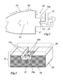
- FIG. 1 A typical combustor arrangement with a reheat combustion chamber of a gas turbine is sketched in Fig. 1 (see for example document WO 2011/061059 A2 ).
- the combustor arrangement 10 of Fig. 1 comprises a hot gas channel 12 coming from a first gas turbine stage and opening into the combustion chamber is 11, which is bordered by a wall 17.
- a fuel injection device 13 (burner) is positioned to inject a fuel 14 into a stream of hot gas flowing through the hot gas channel 12.
- the reheated hot gas 15 is used to drive the gas turbine by means of subsequent turbine stages (not shown).
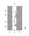
- Fig. 2 shows in a perspective view a panel 23 for such a cooled wall system with near wall cooling.
- the panel 23 comprises a sandwich of a base plate 19 with an open cooling channel 21 in form of a recess, and a covering layer 20 (dashed lines) on top of the base plate 19, which covering layer 20 closes the cooling channel 21.
- the base plate 19 and the covering layer 20 are preferably joined by a brazing process.
- a plurality of exemplary micro-structures 22a, 22b is arranged on the lower channel bordering surface 29a, which is the bottom of the cooling channel recess.
- Two types of micro-structures are shown by example, one type (22b) having a simple geometrical form of a vertically standing cylindrical pin, while the other type (22a) has the vortex generating form of an oblique pyramid.
- These micro-structures 22a,b create a turbulent flow within the cooling channel 21, thereby enhancing the heat transfer between the base plate 19, which is exposed to the hot gas of the gas turbine with its hot side 18, and the cooling fluid (air) flowing through the cooling channel 21.
- the cross section of a closed cooling channel can be seen in Fig. 3, Fig. 4 and Fig. 5 .
- the sandwich panel 23a of Fig. 3 has a near wall cooling channel 21 with simple micro-structures 22b in form of cylindrical pins.
- the micro-structures are not only placed on the channel bordering surface 29a of the base plate 19, but also on the opposite channel bordering surface 29b of the covering layer 20.
- the sandwich panel 23b of Fig. 4 is similar to the sandwich panel 23a of Fig. 3 , but its cooling channel 21 is equipped with advanced micro-structures 22a in the form of oblique pyramids for finest vortex generation.
- the sandwich panel 23c of Fig. 5 shows a different sandwich structure.
- Base plate 19 has, in this case, no recess.
- the cooling channel 21 is created by providing an intermediate layer 24 with a respective opening, which is arranged between the base plate 19 and the covering layer 20 to make up a three-layer sandwich structure.
- the micro-structures 22a again are placed on the channel bordering surfaces 29a and 29b of the base plate 19 and the covering layer 20, respectively.
- the general aim of the micro-structures 22a,b is to produce turbulences for enhanced mixing of cold air in the middle section of the cooling air with hot air on the boundary layers (see Fig. 6 showing the vortex flow structures 25a and 25b).
- turbulences 25a,b
- This is desired in order to achieve a low increase in pressure drop while increasing the heat transfer coefficient considerably.
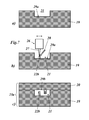
- a base plate 19 with a recess is provided, the bottom of which is the channel bordering surface 29a of the later cooling channel 21.
- the recess may have a width and a depth of some millimetres.
- micro-structures 22b are generated on the channel bordering surface 29a or bottom of the recess by means of a ⁇ -LMF process with an automatic, robot-like, computer-controlled LMF device 26, whereby a focussed laser beam 27 melts a supplied powder material in an additive manufacturing process.
- a third step ( Fig. 7c ) the cooling channel 21 is closed and the panel 23a finished by brazing a covering layer 20 onto the base plate 19.
- the covering layer 20 may have its own micro-structures on its respective channel bordering surface 29b, which may have been applied by a separate ⁇ -LMF process step before.
- the micro-structures can be provided at one or both of the channel bordering surfaces 29a,b.
- Fig. 8 shows a photograph of an exemplary base plate 19 with a plurality of parallel recesses/cooling channels 21, at least one of which is provided with a micro-structure 22c in form of an oblique rib, which has been manufactured by a ⁇ -LMF process according to an embodiment of the invention.
- this HTC enhancement inside cooling channels can be used in further improvements of AcoustiCool SEV front panels, as shown in document EP 2 295 864 A1 .
Landscapes
- Engineering & Computer Science (AREA)
- Chemical & Material Sciences (AREA)
- Combustion & Propulsion (AREA)
- Mechanical Engineering (AREA)
- General Engineering & Computer Science (AREA)
- Turbine Rotor Nozzle Sealing (AREA)
Priority Applications (1)
| Application Number | Priority Date | Filing Date | Title |
|---|---|---|---|
| EP12175713.2A EP2685170A1 (fr) | 2012-07-10 | 2012-07-10 | Structure de paroi refroidie pour les parties chaudes d'une turbine à gaz et procédé de fabrication d'une telle structure |
Applications Claiming Priority (1)
| Application Number | Priority Date | Filing Date | Title |
|---|---|---|---|
| EP12175713.2A EP2685170A1 (fr) | 2012-07-10 | 2012-07-10 | Structure de paroi refroidie pour les parties chaudes d'une turbine à gaz et procédé de fabrication d'une telle structure |
Publications (1)
| Publication Number | Publication Date |
|---|---|
| EP2685170A1 true EP2685170A1 (fr) | 2014-01-15 |
Family
ID=46466322
Family Applications (1)
| Application Number | Title | Priority Date | Filing Date |
|---|---|---|---|
| EP12175713.2A Withdrawn EP2685170A1 (fr) | 2012-07-10 | 2012-07-10 | Structure de paroi refroidie pour les parties chaudes d'une turbine à gaz et procédé de fabrication d'une telle structure |
Country Status (1)
| Country | Link |
|---|---|
| EP (1) | EP2685170A1 (fr) |
Cited By (14)
| Publication number | Priority date | Publication date | Assignee | Title |
|---|---|---|---|---|
| WO2015112384A1 (fr) * | 2014-01-22 | 2015-07-30 | United Technologies Corporation | Procédé de fabrication additive de canaux internes |
| WO2017029090A1 (fr) * | 2015-08-20 | 2017-02-23 | Siemens Aktiengesellschaft | Turbine à gaz comprenant au moins une chambre de combustion tubulaire, et procédé servant à fabriquer une paroi de chambre de combustion |
| US10010937B2 (en) | 2015-11-09 | 2018-07-03 | General Electric Company | Additive manufacturing method for making overhanging tabs in cooling holes |
| US10260354B2 (en) | 2016-02-12 | 2019-04-16 | General Electric Company | Airfoil trailing edge cooling |
| US10350684B2 (en) | 2015-11-10 | 2019-07-16 | General Electric Company | Additive manufacturing method for making complex film holes |
| US10487677B2 (en) | 2015-11-10 | 2019-11-26 | General Electric Company | Turbine component having a seal slot and additive manufacturing process for making same |
| US10487664B2 (en) | 2015-11-09 | 2019-11-26 | General Electric Company | Additive manufacturing method for making holes bounded by thin walls in turbine components |
| US10495309B2 (en) | 2016-02-12 | 2019-12-03 | General Electric Company | Surface contouring of a flowpath wall of a gas turbine engine |
| EP3591295A1 (fr) * | 2018-07-06 | 2020-01-08 | Rolls-Royce North American Technologies, Inc. | Générateurs de turbulences pour refroidir un bouclier thermique de chambre de combustion |
| EP3053674B1 (fr) * | 2015-02-03 | 2020-04-01 | Ansaldo Energia IP UK Limited | Procédé de fabrication d'un panneau avant de chambre de combustion et panneau avant de chambre de combustion |
| CN111059570A (zh) * | 2019-12-31 | 2020-04-24 | 湖南云顶智能科技有限公司 | 一种条状型槽道结构的分体燃烧室 |
| US11390551B2 (en) | 2019-10-01 | 2022-07-19 | Owens-Brockway Glass Container Inc. | Cooling panel for a melter |
| US11747018B2 (en) | 2022-01-05 | 2023-09-05 | General Electric Company | Combustor with dilution openings |
| US11912608B2 (en) | 2019-10-01 | 2024-02-27 | Owens-Brockway Glass Container Inc. | Glass manufacturing |
Citations (9)
| Publication number | Priority date | Publication date | Assignee | Title |
|---|---|---|---|---|
| US4064300A (en) * | 1975-07-16 | 1977-12-20 | Rolls-Royce Limited | Laminated materials |
| US5353865A (en) | 1992-03-30 | 1994-10-11 | General Electric Company | Enhanced impingement cooled components |
| DE19944923A1 (de) * | 1999-09-20 | 2001-03-22 | Asea Brown Boveri | Turbinenschaufel für den Rotor einer Gasturbine |
| DE10248548A1 (de) * | 2002-10-18 | 2004-04-29 | Alstom (Switzerland) Ltd. | Kühlbares Bauteil |
| DE102005038395A1 (de) * | 2004-08-26 | 2006-03-02 | General Electric Co. | Brennkammerkühlung mit geneigten segmentierten Flächen |
| EP1983265A2 (fr) | 2007-04-17 | 2008-10-22 | Rolls-Royce Deutschland Ltd & Co KG | Paroi de chambre de combustion de turbine à gaz |
| EP2199674A1 (fr) | 2008-12-19 | 2010-06-23 | ALSTOM Technology Ltd | Brûleur d'une turbine à gaz |
| EP2295864A1 (fr) | 2009-08-31 | 2011-03-16 | Alstom Technology Ltd | Dispositif de combustion de turbine à gaz |
| WO2011061059A2 (fr) | 2009-11-17 | 2011-05-26 | Alstom Technology Ltd | Chambre de combustion à réchauffe pour moteur à turbine à gaz |
-
2012
- 2012-07-10 EP EP12175713.2A patent/EP2685170A1/fr not_active Withdrawn
Patent Citations (9)
| Publication number | Priority date | Publication date | Assignee | Title |
|---|---|---|---|---|
| US4064300A (en) * | 1975-07-16 | 1977-12-20 | Rolls-Royce Limited | Laminated materials |
| US5353865A (en) | 1992-03-30 | 1994-10-11 | General Electric Company | Enhanced impingement cooled components |
| DE19944923A1 (de) * | 1999-09-20 | 2001-03-22 | Asea Brown Boveri | Turbinenschaufel für den Rotor einer Gasturbine |
| DE10248548A1 (de) * | 2002-10-18 | 2004-04-29 | Alstom (Switzerland) Ltd. | Kühlbares Bauteil |
| DE102005038395A1 (de) * | 2004-08-26 | 2006-03-02 | General Electric Co. | Brennkammerkühlung mit geneigten segmentierten Flächen |
| EP1983265A2 (fr) | 2007-04-17 | 2008-10-22 | Rolls-Royce Deutschland Ltd & Co KG | Paroi de chambre de combustion de turbine à gaz |
| EP2199674A1 (fr) | 2008-12-19 | 2010-06-23 | ALSTOM Technology Ltd | Brûleur d'une turbine à gaz |
| EP2295864A1 (fr) | 2009-08-31 | 2011-03-16 | Alstom Technology Ltd | Dispositif de combustion de turbine à gaz |
| WO2011061059A2 (fr) | 2009-11-17 | 2011-05-26 | Alstom Technology Ltd | Chambre de combustion à réchauffe pour moteur à turbine à gaz |
Non-Patent Citations (1)
| Title |
|---|
| MEIS M. ET AL.: "Heat transfer enhancement in micro-channels caused by vortex promoters", INTERNATIONAL JOURNAL OF HEAT AND MASS TRANSFER, vol. 53, 2010, pages 29 - 40 |
Cited By (18)
| Publication number | Priority date | Publication date | Assignee | Title |
|---|---|---|---|---|
| WO2015112384A1 (fr) * | 2014-01-22 | 2015-07-30 | United Technologies Corporation | Procédé de fabrication additive de canaux internes |
| US9713843B2 (en) | 2014-01-22 | 2017-07-25 | United Technologies Corporation | Method for additively constructing internal channels |
| EP3053674B1 (fr) * | 2015-02-03 | 2020-04-01 | Ansaldo Energia IP UK Limited | Procédé de fabrication d'un panneau avant de chambre de combustion et panneau avant de chambre de combustion |
| WO2017029090A1 (fr) * | 2015-08-20 | 2017-02-23 | Siemens Aktiengesellschaft | Turbine à gaz comprenant au moins une chambre de combustion tubulaire, et procédé servant à fabriquer une paroi de chambre de combustion |
| DE102015215934A1 (de) * | 2015-08-20 | 2017-02-23 | Siemens Aktiengesellschaft | Gasturbine mit mindestens einer Rohrbrennkammer und Verfahren zur Herstellung einer Brennkammerwand |
| US10487664B2 (en) | 2015-11-09 | 2019-11-26 | General Electric Company | Additive manufacturing method for making holes bounded by thin walls in turbine components |
| US10010937B2 (en) | 2015-11-09 | 2018-07-03 | General Electric Company | Additive manufacturing method for making overhanging tabs in cooling holes |
| US11713682B2 (en) | 2015-11-09 | 2023-08-01 | General Electric Company | Additive manufacturing method for making holes bounded by thin walls in turbine components |
| US10350684B2 (en) | 2015-11-10 | 2019-07-16 | General Electric Company | Additive manufacturing method for making complex film holes |
| US10487677B2 (en) | 2015-11-10 | 2019-11-26 | General Electric Company | Turbine component having a seal slot and additive manufacturing process for making same |
| US10260354B2 (en) | 2016-02-12 | 2019-04-16 | General Electric Company | Airfoil trailing edge cooling |
| US10495309B2 (en) | 2016-02-12 | 2019-12-03 | General Electric Company | Surface contouring of a flowpath wall of a gas turbine engine |
| EP3591295A1 (fr) * | 2018-07-06 | 2020-01-08 | Rolls-Royce North American Technologies, Inc. | Générateurs de turbulences pour refroidir un bouclier thermique de chambre de combustion |
| US10851996B2 (en) | 2018-07-06 | 2020-12-01 | Rolls-Royce North American Technologies Inc. | Turbulators for cooling heat shield of a combustor |
| US11390551B2 (en) | 2019-10-01 | 2022-07-19 | Owens-Brockway Glass Container Inc. | Cooling panel for a melter |
| US11912608B2 (en) | 2019-10-01 | 2024-02-27 | Owens-Brockway Glass Container Inc. | Glass manufacturing |
| CN111059570A (zh) * | 2019-12-31 | 2020-04-24 | 湖南云顶智能科技有限公司 | 一种条状型槽道结构的分体燃烧室 |
| US11747018B2 (en) | 2022-01-05 | 2023-09-05 | General Electric Company | Combustor with dilution openings |
Similar Documents
| Publication | Publication Date | Title |
|---|---|---|
| EP2685170A1 (fr) | Structure de paroi refroidie pour les parties chaudes d'une turbine à gaz et procédé de fabrication d'une telle structure | |
| CN102401383B (zh) | 用于冷却燃烧器的装置和方法 | |
| KR101574980B1 (ko) | 가스 터빈 연소기를 위한 감쇠 장치 | |
| JP6283232B2 (ja) | マイクロチャンネル冷却構成要素を形成する方法 | |
| JP4689558B2 (ja) | 中空タービン翼 | |
| US20150064019A1 (en) | Gas Turbine Components with Porous Cooling Features | |
| EP2230383A1 (fr) | Aube de turbine avec refroidissement de l'extrémité | |
| KR101556532B1 (ko) | 냉각슬리브를 포함하는 라이너, 플로우슬리브 및 가스터빈연소기 | |
| JP2012077744A (ja) | タービンロータブレードのプラットフォーム領域を冷却するための装置および方法 | |
| JP6967920B2 (ja) | シムベースと、内部に形成された多数のキャビティを備えたガスタービンエンジンのシール及び、ガスタービンエンジンのシールを形成する方法 | |
| WO2019042970A1 (fr) | Paroi d'un composant implanté dans un trajet de gaz chaud et composant implanté dans un trajet de gaz chaud comprenant une paroi | |
| JP2012102726A (ja) | タービンロータブレードのプラットフォーム領域を冷却するための装置、システム、及び方法 | |
| JP2006348938A (ja) | タービンバケット先端キャップ | |
| CN108138583A (zh) | 具有冷却特征部的涡轮机部件及制造和操作这种涡轮机部件的方法 | |
| US20130195650A1 (en) | Gas Turbine Pattern Swirl Film Cooling | |
| CN109348723A (zh) | 具有由凸起肋形成的冲击冷却槽腔和扩散结合至凸起肋的覆盖板的部件 | |
| US20150337667A1 (en) | Airfoil cooling device and method of manufacture | |
| US20130230407A1 (en) | Turbine Bucket with a Core Cavity Having a Contoured Turn | |
| EP3168535A1 (fr) | Corps de forme aérodynamique et procédé de refroidissement d'un corps placé dans un écoulement de fluide chaud | |
| US20140286771A1 (en) | Cooling passages for turbine buckets of a gas turbine engine | |
| JP6647403B2 (ja) | 速度型機関用の構成要素および方法 | |
| JP2015526629A (ja) | 部品及び部品の冷却方法 | |
| US9631813B2 (en) | Insert element for closing an opening inside a wall of a hot gas path component of a gas turbine and method for enhancing operational behaviour of a gas turbine | |
| US11180998B2 (en) | Airfoil with skincore passage resupply | |
| KR102350151B1 (ko) | 터빈 블레이드 및 가스 터빈 |
Legal Events
| Date | Code | Title | Description |
|---|---|---|---|
| PUAI | Public reference made under article 153(3) epc to a published international application that has entered the european phase |
Free format text: ORIGINAL CODE: 0009012 |
|
| AK | Designated contracting states |
Kind code of ref document: A1 Designated state(s): AL AT BE BG CH CY CZ DE DK EE ES FI FR GB GR HR HU IE IS IT LI LT LU LV MC MK MT NL NO PL PT RO RS SE SI SK SM TR |
|
| AX | Request for extension of the european patent |
Extension state: BA ME |
|
| STAA | Information on the status of an ep patent application or granted ep patent |
Free format text: STATUS: THE APPLICATION IS DEEMED TO BE WITHDRAWN |
|
| 18D | Application deemed to be withdrawn |
Effective date: 20140716 |