EP2295782A1 - Schalldämpfervorrichtung für eine Ansaugleitung eines thermischen Motors und Ansaugleitung mit eingebauter Schalldämpfervorrichtung - Google Patents
Schalldämpfervorrichtung für eine Ansaugleitung eines thermischen Motors und Ansaugleitung mit eingebauter Schalldämpfervorrichtung Download PDFInfo
- Publication number
- EP2295782A1 EP2295782A1 EP10175631A EP10175631A EP2295782A1 EP 2295782 A1 EP2295782 A1 EP 2295782A1 EP 10175631 A EP10175631 A EP 10175631A EP 10175631 A EP10175631 A EP 10175631A EP 2295782 A1 EP2295782 A1 EP 2295782A1
- Authority
- EP
- European Patent Office
- Prior art keywords
- chamber
- fluid
- intake line
- housing
- partitions
- Prior art date
- Legal status (The legal status is an assumption and is not a legal conclusion. Google has not performed a legal analysis and makes no representation as to the accuracy of the status listed.)
- Granted
Links
- 230000030279 gene silencing Effects 0.000 title 2
- 239000012530 fluid Substances 0.000 claims abstract description 17
- 238000005192 partition Methods 0.000 claims abstract description 14
- 239000004033 plastic Substances 0.000 claims abstract description 9
- 229920003023 plastic Polymers 0.000 claims abstract description 9
- 239000000463 material Substances 0.000 claims abstract description 6
- 239000002184 metal Substances 0.000 claims abstract description 4
- 238000002485 combustion reaction Methods 0.000 claims description 7
- 230000005484 gravity Effects 0.000 claims description 6
- 230000004323 axial length Effects 0.000 claims description 3
- 238000007599 discharging Methods 0.000 abstract description 2
- 238000003466 welding Methods 0.000 description 4
- 235000008612 Gnetum gnemon Nutrition 0.000 description 2
- 240000000018 Gnetum gnemon Species 0.000 description 2
- 238000009825 accumulation Methods 0.000 description 2
- 230000015572 biosynthetic process Effects 0.000 description 2
- 239000000428 dust Substances 0.000 description 2
- 238000004519 manufacturing process Methods 0.000 description 2
- 239000007787 solid Substances 0.000 description 2
- 230000002238 attenuated effect Effects 0.000 description 1
- 238000007664 blowing Methods 0.000 description 1
- 230000003749 cleanliness Effects 0.000 description 1
- 230000000694 effects Effects 0.000 description 1
- 235000021183 entrée Nutrition 0.000 description 1
- 238000002347 injection Methods 0.000 description 1
- 239000007924 injection Substances 0.000 description 1
- 230000007774 longterm Effects 0.000 description 1
- 235000011837 pasties Nutrition 0.000 description 1
- 230000010349 pulsation Effects 0.000 description 1
- 238000011144 upstream manufacturing Methods 0.000 description 1
Images
Classifications
-
- F—MECHANICAL ENGINEERING; LIGHTING; HEATING; WEAPONS; BLASTING
- F02—COMBUSTION ENGINES; HOT-GAS OR COMBUSTION-PRODUCT ENGINE PLANTS
- F02M—SUPPLYING COMBUSTION ENGINES IN GENERAL WITH COMBUSTIBLE MIXTURES OR CONSTITUENTS THEREOF
- F02M35/00—Combustion-air cleaners, air intakes, intake silencers, or induction systems specially adapted for, or arranged on, internal-combustion engines
- F02M35/10—Air intakes; Induction systems
- F02M35/10314—Materials for intake systems
- F02M35/10321—Plastics; Composites; Rubbers
-
- F—MECHANICAL ENGINEERING; LIGHTING; HEATING; WEAPONS; BLASTING
- F02—COMBUSTION ENGINES; HOT-GAS OR COMBUSTION-PRODUCT ENGINE PLANTS
- F02M—SUPPLYING COMBUSTION ENGINES IN GENERAL WITH COMBUSTIBLE MIXTURES OR CONSTITUENTS THEREOF
- F02M35/00—Combustion-air cleaners, air intakes, intake silencers, or induction systems specially adapted for, or arranged on, internal-combustion engines
- F02M35/12—Intake silencers ; Sound modulation, transmission or amplification
- F02M35/1205—Flow throttling or guiding
- F02M35/1216—Flow throttling or guiding by using a plurality of holes, slits, protrusions, perforations, ribs or the like; Surface structures; Turbulence generators
-
- F—MECHANICAL ENGINEERING; LIGHTING; HEATING; WEAPONS; BLASTING
- F02—COMBUSTION ENGINES; HOT-GAS OR COMBUSTION-PRODUCT ENGINE PLANTS
- F02M—SUPPLYING COMBUSTION ENGINES IN GENERAL WITH COMBUSTIBLE MIXTURES OR CONSTITUENTS THEREOF
- F02M35/00—Combustion-air cleaners, air intakes, intake silencers, or induction systems specially adapted for, or arranged on, internal-combustion engines
- F02M35/12—Intake silencers ; Sound modulation, transmission or amplification
- F02M35/1255—Intake silencers ; Sound modulation, transmission or amplification using resonance
- F02M35/1261—Helmholtz resonators
-
- F—MECHANICAL ENGINEERING; LIGHTING; HEATING; WEAPONS; BLASTING
- F02—COMBUSTION ENGINES; HOT-GAS OR COMBUSTION-PRODUCT ENGINE PLANTS
- F02M—SUPPLYING COMBUSTION ENGINES IN GENERAL WITH COMBUSTIBLE MIXTURES OR CONSTITUENTS THEREOF
- F02M35/00—Combustion-air cleaners, air intakes, intake silencers, or induction systems specially adapted for, or arranged on, internal-combustion engines
- F02M35/12—Intake silencers ; Sound modulation, transmission or amplification
- F02M35/1255—Intake silencers ; Sound modulation, transmission or amplification using resonance
- F02M35/1266—Intake silencers ; Sound modulation, transmission or amplification using resonance comprising multiple chambers or compartments
-
- F—MECHANICAL ENGINEERING; LIGHTING; HEATING; WEAPONS; BLASTING
- F02—COMBUSTION ENGINES; HOT-GAS OR COMBUSTION-PRODUCT ENGINE PLANTS
- F02M—SUPPLYING COMBUSTION ENGINES IN GENERAL WITH COMBUSTIBLE MIXTURES OR CONSTITUENTS THEREOF
- F02M35/00—Combustion-air cleaners, air intakes, intake silencers, or induction systems specially adapted for, or arranged on, internal-combustion engines
- F02M35/12—Intake silencers ; Sound modulation, transmission or amplification
- F02M35/1283—Manufacturing or assembly; Connectors; Fixations
-
- F—MECHANICAL ENGINEERING; LIGHTING; HEATING; WEAPONS; BLASTING
- F16—ENGINEERING ELEMENTS AND UNITS; GENERAL MEASURES FOR PRODUCING AND MAINTAINING EFFECTIVE FUNCTIONING OF MACHINES OR INSTALLATIONS; THERMAL INSULATION IN GENERAL
- F16L—PIPES; JOINTS OR FITTINGS FOR PIPES; SUPPORTS FOR PIPES, CABLES OR PROTECTIVE TUBING; MEANS FOR THERMAL INSULATION IN GENERAL
- F16L55/00—Devices or appurtenances for use in, or in connection with, pipes or pipe systems
- F16L55/02—Energy absorbers; Noise absorbers
- F16L55/027—Throttle passages
- F16L55/02781—The regulating element being provided with radial outputs
-
- F—MECHANICAL ENGINEERING; LIGHTING; HEATING; WEAPONS; BLASTING
- F16—ENGINEERING ELEMENTS AND UNITS; GENERAL MEASURES FOR PRODUCING AND MAINTAINING EFFECTIVE FUNCTIONING OF MACHINES OR INSTALLATIONS; THERMAL INSULATION IN GENERAL
- F16L—PIPES; JOINTS OR FITTINGS FOR PIPES; SUPPORTS FOR PIPES, CABLES OR PROTECTIVE TUBING; MEANS FOR THERMAL INSULATION IN GENERAL
- F16L55/00—Devices or appurtenances for use in, or in connection with, pipes or pipe systems
- F16L55/02—Energy absorbers; Noise absorbers
- F16L55/033—Noise absorbers
-
- F—MECHANICAL ENGINEERING; LIGHTING; HEATING; WEAPONS; BLASTING
- F02—COMBUSTION ENGINES; HOT-GAS OR COMBUSTION-PRODUCT ENGINE PLANTS
- F02B—INTERNAL-COMBUSTION PISTON ENGINES; COMBUSTION ENGINES IN GENERAL
- F02B37/00—Engines characterised by provision of pumps driven at least for part of the time by exhaust
-
- F—MECHANICAL ENGINEERING; LIGHTING; HEATING; WEAPONS; BLASTING
- F02—COMBUSTION ENGINES; HOT-GAS OR COMBUSTION-PRODUCT ENGINE PLANTS
- F02M—SUPPLYING COMBUSTION ENGINES IN GENERAL WITH COMBUSTIBLE MIXTURES OR CONSTITUENTS THEREOF
- F02M35/00—Combustion-air cleaners, air intakes, intake silencers, or induction systems specially adapted for, or arranged on, internal-combustion engines
- F02M35/02—Air cleaners
- F02M35/022—Air cleaners acting by gravity, by centrifugal, or by other inertial forces, e.g. with moistened walls
-
- F—MECHANICAL ENGINEERING; LIGHTING; HEATING; WEAPONS; BLASTING
- F02—COMBUSTION ENGINES; HOT-GAS OR COMBUSTION-PRODUCT ENGINE PLANTS
- F02M—SUPPLYING COMBUSTION ENGINES IN GENERAL WITH COMBUSTIBLE MIXTURES OR CONSTITUENTS THEREOF
- F02M35/00—Combustion-air cleaners, air intakes, intake silencers, or induction systems specially adapted for, or arranged on, internal-combustion engines
- F02M35/02—Air cleaners
- F02M35/08—Air cleaners with means for removing dust, particles or liquids from cleaners; with means for indicating clogging; with by-pass means; Regeneration of cleaners
Definitions
- the present invention relates to an acoustic attenuation device for an intake line of an internal combustion engine, such as a turbocharged engine for a motor vehicle, and such an intake line incorporating it.
- the invention applies to such an attenuation device resonator chamber (s) resonator (s) of Helmholtz.
- a major disadvantage of the known attenuation devices of the annular resonance chamber type lies in their relatively large size and in the reduced number of resonance chambers formed, which is generally limited to two, which penalizes the acoustic performance for a length of 30 seconds. given device.
- the known attenuation devices of Helmholtz resonator type have in particular the disadvantage of providing more or less long term acoustic attenuation. unsatisfactory, both for the blast noises generated by the turbocharged engine (resulting in pressure pulsations in the low frequencies typically ranging from 1300 to 2000 Hz approximately) that for the hissing noises also generated by this engine (high frequencies beyond about 2500 Hz).
- Helmholtz resonator devices also sometimes have the disadvantage of requiring the welding of several plastic parts together, such as for example the welding of a cover on the wall of the chamber (s) of resonance, which penalizes the manufacturing process of the device in terms of cleanliness, heaviness of implementation and cost, also potentially harming the pressure resistance and the acoustic performance of the device, in particular because of the difficulties in controlling geometric tolerances and / or deformations of the plastic material welded under the effect of the temperature can generate air leaks.
- a device is such that the or each resonance chamber further comprises at least one gravity evacuation orifice driven by the fluid, such as the oil, which orifice is formed in said wall in the immediate vicinity of one of said transverse partitions, the or each chamber being delimited transversely by two longitudinal walls which extend parallel to the axial direction of the structure and which are connected between they by these transverse partitions forming a housing which is closed fluid-tight by a lid formed integrally with this housing.
- the fluid such as the oil
- the or each condensate discharge orifice provided in a Helmholtz resonator according to the invention makes it possible in particular to prevent the accumulation, in the or each resonator, of hot oil and dust entrained by the fluid coming from of the motor and condensing in contact with the walls, accumulation which forms in the long run a solid pasty deposit reducing the useful volume of the corresponding chamber and thus penalizing the acoustic attenuation.
- this gravity evacuation of the condensates provided by the attenuation device according to the invention thus makes it possible to sustain the acoustic performances of the or each Helmholtz resonator which it comprises.
- the or each evacuation orifice arranged according to the invention also makes it possible to advantageously influence this acoustic attenuation by shifting the frequency band which corresponds, on the acoustic attenuation curve, to a high frequency.
- this one-piece formation of the cover with the transverse and longitudinal partitions of the or each resonance chamber overcomes the aforementioned drawback of the prior art relating to the welding between plastic parts, which avoids the pollution of the device during welding and makes it perfectly airtight at the lid.
- this one-piece structure simplifies the manufacturing process of the device according to the invention and therefore reduces its cost of implementation.
- the housing and the cover can be formed in one piece with a duct radially.
- at least one anti-creep metal ring which is provided with said or each opening passage and said or each orifice of evacuation can be inserted against the radially inner face of this conduit to enable it to withstand high operating temperatures, so that the fluid flowing inside the or each ring communicates directly with the or each chamber facing .
- the anti-creep ring (s) is (are) insertable (s) force against the radially inner face of the duct over substantially the entire axial length of this duct.
- this can extend almost over the entire axial length of the device while in a variant of the invention with two anti-creep rings. coaxial flows put end to end, the opposite ends of these two rings may coincide substantially with those of the device.
- said or each discharge orifice may be formed at a corner of the corresponding chamber which is intended to form the lowest point thereof in the mounted state in said line of admission (ie the lowest operating area of said wall forming the bottom of the chamber).
- each chamber could for example have not one, but two identical discharge holes that would be formed axially opposite to each other on said wall and one or the other would allow the evacuation of condensates, according to its position due to the orientation of the pipe structure once integrated into the intake line.
- the attenuation device according to the invention makes it possible in particular to generate reduced pressure losses for the fluid circulating therein, which contributes to improving the performance of the engine, in comparison with known attenuation devices with two annular chambers of resonance that generate higher pressure drops.
- said or each chamber may preferably be arranged radially outside and axially inside said pipe structure. Even more preferably, said or each resonance chamber may have substantially a rectangular parallelepiped shape truncated by said wall.
- said or each discharge orifice may have a passage section which is smaller than that of said or each passage opening for the fluid and which preferably has a substantially circular shape.
- said or each passage opening for the fluid then preferably has an oblong shape in an arc of a circle which extends transversely to this axial direction, substantially of one of these longitudinal walls. to the other.
- Said or each chamber may for example comprise two parallel passage openings which are formed in an axially central zone for this chamber, and a single discharge orifice which is preferably remote from the opening closest to an upper axial distance to that separating the two openings between them.
- this attenuation device may comprise at least one row of said resonance chambers which succeed one another in the axial direction of said pipe structure, the two end chambers of the or each row being able to be respectively defined axially by two transverse end walls which connect these two longitudinal walls together forming with them said housing which is closed by said cover.
- the attenuation device according to the invention can thus advantageously comprise a large number of Helmhotz resonators for a relatively small bulk, especially in comparison with the known attenuation devices with annular resonance chambers, while being adaptable to any environment for mounting in an intake line.
- An intake line according to the invention of an internal combustion engine such as a turbocharged engine for a motor vehicle, comprises at least one acoustic attenuation device according to the invention as defined above, in which said or each discharge orifice is formed at a lower corner of the corresponding resonance chamber to allow the gravitational evacuation of said condensates through this orifice.
- this acoustic attenuation device is to attenuate the noises of breath and / or whistling of an internal combustion engine, such as a turbocharged engine for a motor vehicle.
- breath noise attenuated by the device of the invention relate in particular to a frequency range from 1300 to 2000 Hz.
- these whistling noises they refer in particular to a range of frequencies that can vary from 2500 to 3500 Hz approximately. .
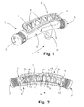
- the housing 6 is formed integrally with the pipe 4 by overcoming it radially outwardly, and the resonance chambers 8 which it delimits communicate each with the interior of the pipe 4 by slots 9 and 10 formed through the wall of each ring 4b, 4c.
- This housing 6 has a substantially rectangular section and is delimited by two longitudinal walls 11 and 12 (which extend parallel to the axial direction A of the pipe 4) interconnected by two transverse walls or end walls 13 and 14 and in this example, by several intermediate partitions 15.
- each chamber 8 has substantially a rectangular parallelepiped shape truncated by the wall of the corresponding ring 4b, 4c forming its bottom and surmounted by the cover 7, and is delimited by the two longitudinal walls 11 and 12 and two transverse partitions 13, 14, 15 (perpendicular to this axial direction A).
- Each chamber 8 has for example a pair of oblong slots 9 and 10 parallel for the passage of air which are formed transversely at its bottom by the ring 4b, 4c, in an axially central zone for this chamber 8.
- Each transverse slot 9 , 10 presents preferably an arcuate shape which extends substantially from one of the longitudinal walls 11 to the other 12.
- each chamber 8 forms not only a one-piece assembly (cover 7 included) with the duct 4, but also comprises at its bottom, in addition to the slots 9 and 10 for the circulation of the air coming from the duct 4, at least one orifice 16 capable of discharging by gravity the condensed oil and the dusts whose air is charged and which are housed in operation in each chamber 8. More precisely, this orifice 16 is formed in the ring 4b, 4c in the immediate vicinity of one end of the two transverse partitions 14, 15 delimiting the chamber 8 which is intended to form its lowest point in the mounted state in the air intake line (ie in the corner the lowest of the chamber 8 in operation).
- the discharge orifice 16 of each chamber 8 preferably has a circular shape and a passage section which is very small in comparison with that of each slot 9, 10, and this orifice 16 is advantageously distant from the slot 10a. closer to an axial distance greater than that separating the two slots 9 and 10 between them.
- these discharge orifices 16 make it possible on the one hand to avoid the formation in each resonator 8 of a solid deposit of oil and dust reducing its useful volume, thereby perpetuating the acoustic performances obtained and, on the other hand, to influence the acoustic attenuation by shifting to high frequencies the band corresponding to an acoustic attenuation range with a level equal to or greater than 20 dB, typically.
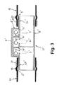
- the acoustic attenuation device 1 'of the figure 3 has two anti-creep rings 4b 'and 4c' similar to those of Figures 1 and 2 , being reminded that a device according to the invention could comprise a single anti-creep ring extending over the entire length of the pipe 4 'of plastic material.
Applications Claiming Priority (1)
| Application Number | Priority Date | Filing Date | Title |
|---|---|---|---|
| FR0904336A FR2950112B1 (fr) | 2009-09-11 | 2009-09-11 | Dispositif d'attenuation acoustique pour ligne d'admission d'un moteur thermique, et ligne d'admission l'incorporant |
Publications (2)
| Publication Number | Publication Date |
|---|---|
| EP2295782A1 true EP2295782A1 (de) | 2011-03-16 |
| EP2295782B1 EP2295782B1 (de) | 2012-07-25 |
Family
ID=41718223
Family Applications (1)
| Application Number | Title | Priority Date | Filing Date |
|---|---|---|---|
| EP10175631A Not-in-force EP2295782B1 (de) | 2009-09-11 | 2010-09-07 | Schalldämpfervorrichtung für eine Ansaugleitung eines thermischen Motors und Ansaugleitung mit eingebauter Schalldämpfervorrichtung |
Country Status (4)
| Country | Link |
|---|---|
| US (1) | US8177024B2 (de) |
| EP (1) | EP2295782B1 (de) |
| ES (1) | ES2393867T3 (de) |
| FR (1) | FR2950112B1 (de) |
Cited By (4)
| Publication number | Priority date | Publication date | Assignee | Title |
|---|---|---|---|---|
| EP2693040A1 (de) * | 2012-07-31 | 2014-02-05 | Aisin Seiki Kabushiki Kaisha | Ansaugkrümmer |
| WO2016191780A1 (de) * | 2015-05-29 | 2016-12-08 | Henn Gmbh & Co Kg. | Fahrzeugschalldämpfer |
| CN108204317A (zh) * | 2016-12-19 | 2018-06-26 | 上海欧菲滤清器有限公司 | 进气管道 |
| CN108412649A (zh) * | 2018-05-10 | 2018-08-17 | 上海亿泊材料应用技术有限公司 | 一种发动机降噪装置及发动机 |
Families Citing this family (15)
| Publication number | Priority date | Publication date | Assignee | Title |
|---|---|---|---|---|
| CN106122111A (zh) * | 2009-05-18 | 2016-11-16 | 博格华纳公司 | 排气涡轮增压器的压缩机 |
| FR2961286B1 (fr) * | 2010-06-14 | 2015-01-02 | Hutchinson | Tuyau pour circuit d'admission d'air de moteur de vehicule automobile, et ce circuit l'incorporant |
| US9121374B2 (en) * | 2010-10-22 | 2015-09-01 | Umfotec Umformtechnik Gmbh | Wide-band damper for charge air lines of an internal combustion engine with turbocharger |
| US8381871B1 (en) * | 2011-09-28 | 2013-02-26 | Visteon Global Technologies, Inc. | Compact low frequency resonator |
| GB2496368B (en) * | 2011-10-12 | 2017-05-31 | Ford Global Tech Llc | An acoustic attenuator for an engine booster |
| EP2623732A1 (de) * | 2012-02-02 | 2013-08-07 | Siemens Aktiengesellschaft | Anlage und Verfahren zur Dämpfung akustischer Schwingungen bei einer entsprechenden Anlage |
| WO2014051937A1 (en) * | 2012-09-27 | 2014-04-03 | Eaton Corporation | Integral resonators for roots-type supercharger |
| US9175648B2 (en) * | 2013-10-17 | 2015-11-03 | Ford Global Technologies, Llc | Intake system having a silencer device |
| GB2520749A (en) * | 2013-11-29 | 2015-06-03 | Ge Oil & Gas Uk Ltd | Fluid flow |
| ES2681280T3 (es) * | 2014-02-13 | 2018-09-12 | Ls Mtron Ltd. | Resonador para vehículo |
| CN106460737A (zh) | 2014-05-19 | 2017-02-22 | 伊顿公司 | 增压器出口共振器 |
| US9697817B2 (en) | 2015-05-14 | 2017-07-04 | Zin Technologies, Inc. | Tunable acoustic attenuation |
| US20180202334A1 (en) * | 2017-01-16 | 2018-07-19 | Indmar Products Company Inc. | Exhaust Muffler For Marine Engine Exhaust System |
| DE102017130661A1 (de) * | 2017-12-20 | 2019-06-27 | Montaplast Gmbh | Breitbanddämpfer für einen Kraftfahrzeug-Motor |
| DE102021205772A1 (de) | 2021-06-08 | 2022-12-08 | Mahle Anand Filter Systems Private Limited | Schalldämpfeinrichtung |
Citations (9)
| Publication number | Priority date | Publication date | Assignee | Title |
|---|---|---|---|---|
| US3323613A (en) * | 1964-10-26 | 1967-06-06 | Walker Mfg Co | Three-part muffler with side branch chambers |
| JPH0890641A (ja) * | 1994-09-21 | 1996-04-09 | Inoac Corp | レゾネータ付きエアクリーナホース |
| JP2000240520A (ja) * | 1999-02-19 | 2000-09-05 | Kojima Press Co Ltd | 消音器 |
| DE19956172A1 (de) | 1999-11-23 | 2001-05-31 | Umfotec Umformtechnik Gmbh | Doppelkammerdämpfer |
| EP1128071A2 (de) * | 2000-02-25 | 2001-08-29 | Inoac Corporation | Lüfterzarge mit integriertem Resonator |
| EP1352172B1 (de) | 2001-01-18 | 2004-12-01 | MAHLE Filtersysteme GmbH | Schalldämpfer mit einer mehrzahl an resonanzkammern |
| JP2007016652A (ja) * | 2005-07-06 | 2007-01-25 | Tigers Polymer Corp | 吸気装置 |
| EP1795733A1 (de) * | 2005-12-12 | 2007-06-13 | Trelleborg Fluid & Acoustic Solutions (TFAS) | Schalldämpfer zur Verringerung von Luftgeräuschen, insbesondre für interne Brennkraftmaschinen |
| FR2895030A1 (fr) * | 2005-12-15 | 2007-06-22 | Denso Corp | Dispositif d'admission et systeme d'admission |
Family Cites Families (11)
| Publication number | Priority date | Publication date | Assignee | Title |
|---|---|---|---|---|
| WO1989005373A1 (en) * | 1987-11-30 | 1989-06-15 | Mitsui Toatsu Chemicals, Incorporated | Resin-coated carbon fibers, heat-resistant resin composition using same, and parts for internal combustion engines |
| US4969536A (en) * | 1989-10-26 | 1990-11-13 | Allied-Signal Inc. | Turbocharger noise silencer |
| IT1278601B1 (it) * | 1994-07-05 | 1997-11-24 | Necchi Compressori | Silenziatore per motocompressore, per apparati frigoriferi |
| JP2003200936A (ja) * | 2001-12-28 | 2003-07-15 | Toyo Roki Mfg Co Ltd | 容器の水抜き穴形状 |
| DE102004028744B3 (de) * | 2004-06-14 | 2005-10-27 | Veritas Ag | Schalldämpfer |
| US20070105531A1 (en) * | 2005-11-04 | 2007-05-10 | Ascenna Mobile, Inc. | Dynamic Processing of Virtual Identities for Mobile Communications Devices |
| JP2008008253A (ja) * | 2006-06-30 | 2008-01-17 | Toyoda Gosei Co Ltd | 消音ダクト |
| US7779822B2 (en) * | 2007-01-12 | 2010-08-24 | Gm Global Technology Operations, Inc. | Intake assembly with integral resonators |
| US20100139604A1 (en) * | 2008-12-09 | 2010-06-10 | Reza Abdolhosseini | Inlet mechanism for an air induction system |
| US7934581B2 (en) * | 2009-01-30 | 2011-05-03 | Eaton Corporation | Broadband noise resonator |
| US8327975B2 (en) * | 2009-09-30 | 2012-12-11 | Ford Global Technologies, Llc | Acoustic silencer |
-
2009
- 2009-09-11 FR FR0904336A patent/FR2950112B1/fr not_active Expired - Fee Related
-
2010
- 2010-09-07 ES ES10175631T patent/ES2393867T3/es active Active
- 2010-09-07 EP EP10175631A patent/EP2295782B1/de not_active Not-in-force
- 2010-09-10 US US12/879,405 patent/US8177024B2/en active Active
Patent Citations (9)
| Publication number | Priority date | Publication date | Assignee | Title |
|---|---|---|---|---|
| US3323613A (en) * | 1964-10-26 | 1967-06-06 | Walker Mfg Co | Three-part muffler with side branch chambers |
| JPH0890641A (ja) * | 1994-09-21 | 1996-04-09 | Inoac Corp | レゾネータ付きエアクリーナホース |
| JP2000240520A (ja) * | 1999-02-19 | 2000-09-05 | Kojima Press Co Ltd | 消音器 |
| DE19956172A1 (de) | 1999-11-23 | 2001-05-31 | Umfotec Umformtechnik Gmbh | Doppelkammerdämpfer |
| EP1128071A2 (de) * | 2000-02-25 | 2001-08-29 | Inoac Corporation | Lüfterzarge mit integriertem Resonator |
| EP1352172B1 (de) | 2001-01-18 | 2004-12-01 | MAHLE Filtersysteme GmbH | Schalldämpfer mit einer mehrzahl an resonanzkammern |
| JP2007016652A (ja) * | 2005-07-06 | 2007-01-25 | Tigers Polymer Corp | 吸気装置 |
| EP1795733A1 (de) * | 2005-12-12 | 2007-06-13 | Trelleborg Fluid & Acoustic Solutions (TFAS) | Schalldämpfer zur Verringerung von Luftgeräuschen, insbesondre für interne Brennkraftmaschinen |
| FR2895030A1 (fr) * | 2005-12-15 | 2007-06-22 | Denso Corp | Dispositif d'admission et systeme d'admission |
Cited By (7)
| Publication number | Priority date | Publication date | Assignee | Title |
|---|---|---|---|---|
| EP2693040A1 (de) * | 2012-07-31 | 2014-02-05 | Aisin Seiki Kabushiki Kaisha | Ansaugkrümmer |
| US9249765B2 (en) | 2012-07-31 | 2016-02-02 | Aisin Seiki Kabushiki Kaisha | Intake manifold |
| WO2016191780A1 (de) * | 2015-05-29 | 2016-12-08 | Henn Gmbh & Co Kg. | Fahrzeugschalldämpfer |
| KR20180013995A (ko) * | 2015-05-29 | 2018-02-07 | 헨 게엠베하 운트 콤파니 카게. | 차량용 소음기 |
| US10436159B2 (en) | 2015-05-29 | 2019-10-08 | Henn Gmbh & Co Kg. | Vehicle silencer |
| CN108204317A (zh) * | 2016-12-19 | 2018-06-26 | 上海欧菲滤清器有限公司 | 进气管道 |
| CN108412649A (zh) * | 2018-05-10 | 2018-08-17 | 上海亿泊材料应用技术有限公司 | 一种发动机降噪装置及发动机 |
Also Published As
| Publication number | Publication date |
|---|---|
| ES2393867T3 (es) | 2012-12-28 |
| FR2950112B1 (fr) | 2011-10-07 |
| FR2950112A1 (fr) | 2011-03-18 |
| US8177024B2 (en) | 2012-05-15 |
| US20110061970A1 (en) | 2011-03-17 |
| EP2295782B1 (de) | 2012-07-25 |
Similar Documents
| Publication | Publication Date | Title |
|---|---|---|
| EP2295782B1 (de) | Schalldämpfervorrichtung für eine Ansaugleitung eines thermischen Motors und Ansaugleitung mit eingebauter Schalldämpfervorrichtung | |
| CA2908855C (fr) | Dispositif de degivrage d'un bec de separation de turbomachine aeronautique | |
| FR2924764A1 (fr) | Dispositif d'attenuation acoustique pour la ligne d'admission d'un moteur thermique, et ligne d'admission l'incorporant | |
| FR2953142A1 (fr) | Appareil de delivrance regulee d'un gaz,notamment appareil d'assistance respiratoire | |
| EP2647513B1 (de) | Leitung für einen Klimaanlagenkreislauf mit Lärmreduzierungsvorrichtung, und Klimaanlagenkreislauf mit einer solchen Vorrichtung | |
| WO2015079166A1 (fr) | Ensemble de combustion a accès facilite des cannes de prévaporisation | |
| EP2101057B1 (de) | Vorrichtung zur Lärmreduzierung für Einspeiseleitung einer Wärmekraftmaschine und Einspeiseleitung, die diese Vorrichtung umfasst | |
| EP2256330B1 (de) | Ansauggeräuschdämpfer einer Brennkraftmaschine, sowie diesen umfassende Ansaugleitung | |
| FR2884896A1 (fr) | Raccord d'etancheite et ensemble d'un organe de transmission, d'une cartouche de gaz et d'un adaptateur comprenant le raccord | |
| WO2016071623A1 (fr) | Conduit intégrant un dispositif d'atténuation acoustique | |
| EP3303815B1 (de) | Vorrichtung zur dämpfung von verbreiteten und abgestrahlten leitungsgeräuschen | |
| EP2106943B1 (de) | Leitung mit einer Kraftfahrzeugklimaanlagekühlkreisgeräuschdämmungsvorrichtung, und Kühlkreis umfassend einer solchen Leitung | |
| FR2901738A1 (fr) | Dispositif reducteur de bruit pour circuit de climatisation de vehicule automobile, conduite et ce circuit l'incorporant | |
| EP2435685B1 (de) | Fluggasturbine mit schalldämpfer im abgasendstück | |
| EP1553284B1 (de) | Luftansaugdämpfungsanlage, insbesondere für aufgeladene Brennkraftmaschinen oder Klimaanlage, und Ansaugkanal mit solch einer Anlage | |
| FR2624923A1 (fr) | Ventilateur axial ou centrifuge-axial pour la circulation d'un gaz | |
| EP1795733B1 (de) | Schalldämpfer zur Verringerung von Luftgeräuschen, insbesondre für interne Brennkraftmaschinen | |
| EP2128425B1 (de) | Vorrichtung zur Geräuschdämpfung für eine Ansaugleitung einer Brennkraftmaschine und Ansaugleitung, die diese Vorrichtung umfasst | |
| FR2946120A1 (fr) | Dispositif d'attenuation acoustique pour ligne d'admission d'un moteur thermique,et ligne d'admission l'incorporant. | |
| EP3693597A1 (de) | Akustischer resonator | |
| EP2354524B1 (de) | Vorrichtung zur akkustischen Dämpfung für eine Ansaugleitung eines thermischen Motors, flexibles Rohr und Ansaugleitung umfassend eine solche Vorrichtung | |
| FR2937686A1 (fr) | Moteur thermique turbocompresse comportant un circuit d'air simplifie | |
| FR3067064A1 (fr) | Conduit d’admission d’air et d’attenuation des bruits | |
| EP3039257A1 (de) | Schalldämpfer für eine abgasleitung einer wärmekraftmaschine | |
| FR2971031A1 (fr) | Ensemble comportant un conduit de mise a l'air libre d'un circuit de vide et un capuchon optimise, et circuit de vide associe |
Legal Events
| Date | Code | Title | Description |
|---|---|---|---|
| PUAI | Public reference made under article 153(3) epc to a published international application that has entered the european phase |
Free format text: ORIGINAL CODE: 0009012 |
|
| AK | Designated contracting states |
Kind code of ref document: A1 Designated state(s): AL AT BE BG CH CY CZ DE DK EE ES FI FR GB GR HR HU IE IS IT LI LT LU LV MC MK MT NL NO PL PT RO SE SI SK SM TR |
|
| AX | Request for extension of the european patent |
Extension state: BA ME RS |
|
| 17P | Request for examination filed |
Effective date: 20110606 |
|
| GRAP | Despatch of communication of intention to grant a patent |
Free format text: ORIGINAL CODE: EPIDOSNIGR1 |
|
| GRAJ | Information related to disapproval of communication of intention to grant by the applicant or resumption of examination proceedings by the epo deleted |
Free format text: ORIGINAL CODE: EPIDOSDIGR1 |
|
| GRAP | Despatch of communication of intention to grant a patent |
Free format text: ORIGINAL CODE: EPIDOSNIGR1 |
|
| RIC1 | Information provided on ipc code assigned before grant |
Ipc: F02M 35/022 20060101AFI20111202BHEP Ipc: F02M 35/14 20060101ALI20111202BHEP |
|
| GRAC | Information related to communication of intention to grant a patent modified |
Free format text: ORIGINAL CODE: EPIDOSCIGR1 |
|
| GRAS | Grant fee paid |
Free format text: ORIGINAL CODE: EPIDOSNIGR3 |
|
| GRAA | (expected) grant |
Free format text: ORIGINAL CODE: 0009210 |
|
| AK | Designated contracting states |
Kind code of ref document: B1 Designated state(s): AL AT BE BG CH CY CZ DE DK EE ES FI FR GB GR HR HU IE IS IT LI LT LU LV MC MK MT NL NO PL PT RO SE SI SK SM TR |
|
| REG | Reference to a national code |
Ref country code: GB Ref legal event code: FG4D Free format text: NOT ENGLISH |
|
| REG | Reference to a national code |
Ref country code: CH Ref legal event code: EP |
|
| REG | Reference to a national code |
Ref country code: AT Ref legal event code: REF Ref document number: 567829 Country of ref document: AT Kind code of ref document: T Effective date: 20120815 Ref country code: IE Ref legal event code: FG4D Free format text: LANGUAGE OF EP DOCUMENT: FRENCH |
|
| RIN1 | Information on inventor provided before grant (corrected) |
Inventor name: CALISKAN, ALPER |
|
| REG | Reference to a national code |
Ref country code: DE Ref legal event code: R096 Ref document number: 602010002285 Country of ref document: DE Effective date: 20120920 |
|
| REG | Reference to a national code |
Ref country code: NL Ref legal event code: VDEP Effective date: 20120725 |
|
| REG | Reference to a national code |
Ref country code: AT Ref legal event code: MK05 Ref document number: 567829 Country of ref document: AT Kind code of ref document: T Effective date: 20120725 |
|
| REG | Reference to a national code |
Ref country code: LT Ref legal event code: MG4D Effective date: 20120725 |
|
| REG | Reference to a national code |
Ref country code: ES Ref legal event code: FG2A Ref document number: 2393867 Country of ref document: ES Kind code of ref document: T3 Effective date: 20121228 |
|
| PG25 | Lapsed in a contracting state [announced via postgrant information from national office to epo] |
Ref country code: FI Free format text: LAPSE BECAUSE OF FAILURE TO SUBMIT A TRANSLATION OF THE DESCRIPTION OR TO PAY THE FEE WITHIN THE PRESCRIBED TIME-LIMIT Effective date: 20120725 Ref country code: NO Free format text: LAPSE BECAUSE OF FAILURE TO SUBMIT A TRANSLATION OF THE DESCRIPTION OR TO PAY THE FEE WITHIN THE PRESCRIBED TIME-LIMIT Effective date: 20121025 Ref country code: LT Free format text: LAPSE BECAUSE OF FAILURE TO SUBMIT A TRANSLATION OF THE DESCRIPTION OR TO PAY THE FEE WITHIN THE PRESCRIBED TIME-LIMIT Effective date: 20120725 Ref country code: AT Free format text: LAPSE BECAUSE OF FAILURE TO SUBMIT A TRANSLATION OF THE DESCRIPTION OR TO PAY THE FEE WITHIN THE PRESCRIBED TIME-LIMIT Effective date: 20120725 Ref country code: IS Free format text: LAPSE BECAUSE OF FAILURE TO SUBMIT A TRANSLATION OF THE DESCRIPTION OR TO PAY THE FEE WITHIN THE PRESCRIBED TIME-LIMIT Effective date: 20121125 Ref country code: CY Free format text: LAPSE BECAUSE OF FAILURE TO SUBMIT A TRANSLATION OF THE DESCRIPTION OR TO PAY THE FEE WITHIN THE PRESCRIBED TIME-LIMIT Effective date: 20120725 Ref country code: HR Free format text: LAPSE BECAUSE OF FAILURE TO SUBMIT A TRANSLATION OF THE DESCRIPTION OR TO PAY THE FEE WITHIN THE PRESCRIBED TIME-LIMIT Effective date: 20120725 |
|
| PG25 | Lapsed in a contracting state [announced via postgrant information from national office to epo] |
Ref country code: PL Free format text: LAPSE BECAUSE OF FAILURE TO SUBMIT A TRANSLATION OF THE DESCRIPTION OR TO PAY THE FEE WITHIN THE PRESCRIBED TIME-LIMIT Effective date: 20120725 Ref country code: PT Free format text: LAPSE BECAUSE OF FAILURE TO SUBMIT A TRANSLATION OF THE DESCRIPTION OR TO PAY THE FEE WITHIN THE PRESCRIBED TIME-LIMIT Effective date: 20121126 Ref country code: SI Free format text: LAPSE BECAUSE OF FAILURE TO SUBMIT A TRANSLATION OF THE DESCRIPTION OR TO PAY THE FEE WITHIN THE PRESCRIBED TIME-LIMIT Effective date: 20120725 Ref country code: GR Free format text: LAPSE BECAUSE OF FAILURE TO SUBMIT A TRANSLATION OF THE DESCRIPTION OR TO PAY THE FEE WITHIN THE PRESCRIBED TIME-LIMIT Effective date: 20121026 Ref country code: LV Free format text: LAPSE BECAUSE OF FAILURE TO SUBMIT A TRANSLATION OF THE DESCRIPTION OR TO PAY THE FEE WITHIN THE PRESCRIBED TIME-LIMIT Effective date: 20120725 Ref country code: SE Free format text: LAPSE BECAUSE OF FAILURE TO SUBMIT A TRANSLATION OF THE DESCRIPTION OR TO PAY THE FEE WITHIN THE PRESCRIBED TIME-LIMIT Effective date: 20120725 |
|
| PG25 | Lapsed in a contracting state [announced via postgrant information from national office to epo] |
Ref country code: NL Free format text: LAPSE BECAUSE OF FAILURE TO SUBMIT A TRANSLATION OF THE DESCRIPTION OR TO PAY THE FEE WITHIN THE PRESCRIBED TIME-LIMIT Effective date: 20120725 |
|
| BERE | Be: lapsed |
Owner name: HUTCHINSON Effective date: 20120930 |
|
| PG25 | Lapsed in a contracting state [announced via postgrant information from national office to epo] |
Ref country code: MC Free format text: LAPSE BECAUSE OF NON-PAYMENT OF DUE FEES Effective date: 20120930 Ref country code: EE Free format text: LAPSE BECAUSE OF FAILURE TO SUBMIT A TRANSLATION OF THE DESCRIPTION OR TO PAY THE FEE WITHIN THE PRESCRIBED TIME-LIMIT Effective date: 20120725 Ref country code: CZ Free format text: LAPSE BECAUSE OF FAILURE TO SUBMIT A TRANSLATION OF THE DESCRIPTION OR TO PAY THE FEE WITHIN THE PRESCRIBED TIME-LIMIT Effective date: 20120725 Ref country code: DK Free format text: LAPSE BECAUSE OF FAILURE TO SUBMIT A TRANSLATION OF THE DESCRIPTION OR TO PAY THE FEE WITHIN THE PRESCRIBED TIME-LIMIT Effective date: 20120725 Ref country code: RO Free format text: LAPSE BECAUSE OF FAILURE TO SUBMIT A TRANSLATION OF THE DESCRIPTION OR TO PAY THE FEE WITHIN THE PRESCRIBED TIME-LIMIT Effective date: 20120725 |
|
| PG25 | Lapsed in a contracting state [announced via postgrant information from national office to epo] |
Ref country code: SK Free format text: LAPSE BECAUSE OF FAILURE TO SUBMIT A TRANSLATION OF THE DESCRIPTION OR TO PAY THE FEE WITHIN THE PRESCRIBED TIME-LIMIT Effective date: 20120725 |
|
| PLBE | No opposition filed within time limit |
Free format text: ORIGINAL CODE: 0009261 |
|
| STAA | Information on the status of an ep patent application or granted ep patent |
Free format text: STATUS: NO OPPOSITION FILED WITHIN TIME LIMIT |
|
| REG | Reference to a national code |
Ref country code: IE Ref legal event code: MM4A |
|
| 26N | No opposition filed |
Effective date: 20130426 |
|
| PG25 | Lapsed in a contracting state [announced via postgrant information from national office to epo] |
Ref country code: BG Free format text: LAPSE BECAUSE OF FAILURE TO SUBMIT A TRANSLATION OF THE DESCRIPTION OR TO PAY THE FEE WITHIN THE PRESCRIBED TIME-LIMIT Effective date: 20121025 Ref country code: BE Free format text: LAPSE BECAUSE OF NON-PAYMENT OF DUE FEES Effective date: 20120930 Ref country code: IE Free format text: LAPSE BECAUSE OF NON-PAYMENT OF DUE FEES Effective date: 20120907 |
|
| REG | Reference to a national code |
Ref country code: DE Ref legal event code: R097 Ref document number: 602010002285 Country of ref document: DE Effective date: 20130426 |
|
| PG25 | Lapsed in a contracting state [announced via postgrant information from national office to epo] |
Ref country code: MT Free format text: LAPSE BECAUSE OF FAILURE TO SUBMIT A TRANSLATION OF THE DESCRIPTION OR TO PAY THE FEE WITHIN THE PRESCRIBED TIME-LIMIT Effective date: 20120725 Ref country code: AL Free format text: LAPSE BECAUSE OF FAILURE TO SUBMIT A TRANSLATION OF THE DESCRIPTION OR TO PAY THE FEE WITHIN THE PRESCRIBED TIME-LIMIT Effective date: 20120725 |
|
| PG25 | Lapsed in a contracting state [announced via postgrant information from national office to epo] |
Ref country code: TR Free format text: LAPSE BECAUSE OF FAILURE TO SUBMIT A TRANSLATION OF THE DESCRIPTION OR TO PAY THE FEE WITHIN THE PRESCRIBED TIME-LIMIT Effective date: 20120725 |
|
| PG25 | Lapsed in a contracting state [announced via postgrant information from national office to epo] |
Ref country code: SM Free format text: LAPSE BECAUSE OF FAILURE TO SUBMIT A TRANSLATION OF THE DESCRIPTION OR TO PAY THE FEE WITHIN THE PRESCRIBED TIME-LIMIT Effective date: 20120725 Ref country code: LU Free format text: LAPSE BECAUSE OF NON-PAYMENT OF DUE FEES Effective date: 20120907 |
|
| PG25 | Lapsed in a contracting state [announced via postgrant information from national office to epo] |
Ref country code: HU Free format text: LAPSE BECAUSE OF FAILURE TO SUBMIT A TRANSLATION OF THE DESCRIPTION OR TO PAY THE FEE WITHIN THE PRESCRIBED TIME-LIMIT Effective date: 20100907 |
|
| PGFP | Annual fee paid to national office [announced via postgrant information from national office to epo] |
Ref country code: DE Payment date: 20140922 Year of fee payment: 5 |
|
| PGFP | Annual fee paid to national office [announced via postgrant information from national office to epo] |
Ref country code: FR Payment date: 20140828 Year of fee payment: 5 Ref country code: ES Payment date: 20140926 Year of fee payment: 5 |
|
| PGFP | Annual fee paid to national office [announced via postgrant information from national office to epo] |
Ref country code: IT Payment date: 20140925 Year of fee payment: 5 |
|
| REG | Reference to a national code |
Ref country code: CH Ref legal event code: PL |
|
| GBPC | Gb: european patent ceased through non-payment of renewal fee |
Effective date: 20140907 |
|
| PG25 | Lapsed in a contracting state [announced via postgrant information from national office to epo] |
Ref country code: MK Free format text: LAPSE BECAUSE OF FAILURE TO SUBMIT A TRANSLATION OF THE DESCRIPTION OR TO PAY THE FEE WITHIN THE PRESCRIBED TIME-LIMIT Effective date: 20120725 Ref country code: LI Free format text: LAPSE BECAUSE OF NON-PAYMENT OF DUE FEES Effective date: 20140930 Ref country code: GB Free format text: LAPSE BECAUSE OF NON-PAYMENT OF DUE FEES Effective date: 20140907 Ref country code: CH Free format text: LAPSE BECAUSE OF NON-PAYMENT OF DUE FEES Effective date: 20140930 |
|
| REG | Reference to a national code |
Ref country code: DE Ref legal event code: R119 Ref document number: 602010002285 Country of ref document: DE |
|
| PG25 | Lapsed in a contracting state [announced via postgrant information from national office to epo] |
Ref country code: IT Free format text: LAPSE BECAUSE OF NON-PAYMENT OF DUE FEES Effective date: 20150907 |
|
| REG | Reference to a national code |
Ref country code: FR Ref legal event code: ST Effective date: 20160531 |
|
| PG25 | Lapsed in a contracting state [announced via postgrant information from national office to epo] |
Ref country code: DE Free format text: LAPSE BECAUSE OF NON-PAYMENT OF DUE FEES Effective date: 20160401 |
|
| PG25 | Lapsed in a contracting state [announced via postgrant information from national office to epo] |
Ref country code: FR Free format text: LAPSE BECAUSE OF NON-PAYMENT OF DUE FEES Effective date: 20150930 |
|
| REG | Reference to a national code |
Ref country code: ES Ref legal event code: FD2A Effective date: 20161027 |
|
| PG25 | Lapsed in a contracting state [announced via postgrant information from national office to epo] |
Ref country code: ES Free format text: LAPSE BECAUSE OF NON-PAYMENT OF DUE FEES Effective date: 20150908 |