EP2295732A1 - Axialturbine und Verfahren zur Abgabe eines Stroms aus einer Axialturbine - Google Patents
Axialturbine und Verfahren zur Abgabe eines Stroms aus einer Axialturbine Download PDFInfo
- Publication number
- EP2295732A1 EP2295732A1 EP09170201A EP09170201A EP2295732A1 EP 2295732 A1 EP2295732 A1 EP 2295732A1 EP 09170201 A EP09170201 A EP 09170201A EP 09170201 A EP09170201 A EP 09170201A EP 2295732 A1 EP2295732 A1 EP 2295732A1
- Authority
- EP
- European Patent Office
- Prior art keywords
- turbine
- stator blades
- diffuser
- axial
- flow
- Prior art date
- Legal status (The legal status is an assumption and is not a legal conclusion. Google has not performed a legal analysis and makes no representation as to the accuracy of the status listed.)
- Withdrawn
Links
Images

Classifications
-
- F—MECHANICAL ENGINEERING; LIGHTING; HEATING; WEAPONS; BLASTING
- F01—MACHINES OR ENGINES IN GENERAL; ENGINE PLANTS IN GENERAL; STEAM ENGINES
- F01D—NON-POSITIVE DISPLACEMENT MACHINES OR ENGINES, e.g. STEAM TURBINES
- F01D25/00—Component parts, details, or accessories, not provided for in, or of interest apart from, other groups
- F01D25/30—Exhaust heads, chambers, or the like
-
- F—MECHANICAL ENGINEERING; LIGHTING; HEATING; WEAPONS; BLASTING
- F01—MACHINES OR ENGINES IN GENERAL; ENGINE PLANTS IN GENERAL; STEAM ENGINES
- F01D—NON-POSITIVE DISPLACEMENT MACHINES OR ENGINES, e.g. STEAM TURBINES
- F01D9/00—Stators
- F01D9/02—Nozzles; Nozzle boxes; Stator blades; Guide conduits, e.g. individual nozzles
- F01D9/04—Nozzles; Nozzle boxes; Stator blades; Guide conduits, e.g. individual nozzles forming ring or sector
-
- F—MECHANICAL ENGINEERING; LIGHTING; HEATING; WEAPONS; BLASTING
- F05—INDEXING SCHEMES RELATING TO ENGINES OR PUMPS IN VARIOUS SUBCLASSES OF CLASSES F01-F04
- F05D—INDEXING SCHEME FOR ASPECTS RELATING TO NON-POSITIVE-DISPLACEMENT MACHINES OR ENGINES, GAS-TURBINES OR JET-PROPULSION PLANTS
- F05D2220/00—Application
- F05D2220/30—Application in turbines
- F05D2220/31—Application in turbines in steam turbines
Definitions
- the present invention relates to an axial turbine and a method for discharging a flow from an axial turbine, wherein the turbine is a steam turbine.
- the present invention refers to a design for the guide vane of the last stage and/or for the stages upstream and/or downstream of extraction slits, which favourably influences the work extraction and the flow in the exhaust diffuser.
- Steam turbines are known to comprise a cylinder including a plurality of expansion stages made of stator/rotor blades.
- stator blades of each stage are all identical, arranged with identical geometrical configuration (i.e. they have the same stagger angle, etc) and define guide vanes that are identical; in the same way, also the rotor blades of each stage are all identical, are arranged with the same geometrical configuration (i.e. they have the same stagger angle, etc) and define paths that are identical.
- steam turbines Downstream of the expansion stages, steam turbines have an exhaust diffuser that collects the steam coming from the expansion stages and typically (for power production plants) discharges it into a condenser.
- the exhaust diffuser is made of an axial-symmetric portion that gathers the steam coming from the last expansion stage and feeds it to a non axial-symmetric collector, having an upper quasi-circular casing portion and a lower discharging casing portion with a rectangular opening connected to a condenser neck.
- the steam passes through the expansion stages and delivers mechanical power to the rotor blades (and thus to a turbine shaft connected to the rotor blades).
- the technical aim of the present invention is therefore to provide an axial turbine and a method that allow counteracting the flow circumferential distortions caused by the non axial-symmetric configuration of the exhaust diffuser and/or a turbine portion provided with extraction slits.
- an object of the invention is to provide an axial turbine and a method which allow counteracting the non-uniformities of the operating conditions.
- a further object of the invention is to provide an axial turbine and a method by which the mixing losses (due to the above mentioned non-uniformities) and pressure drops of the steam flow are reduced and the overall efficiency of the steam turbine is increased.
- the turbine 1 is a steam turbine and comprises a plurality of expansion stages 2 where the high pressure and high temperature steam flow generated by a steam generator 3 is expanded to extract mechanical power.
- the steam turbine 1 Downstream of the expansion stages 2 the steam turbine 1 comprises an exhaust diffuser 4 that collects the steam flow passing through the expansion stages 2 and discharges it to the outside (into a condenser 5) along a direction different from that of the turbine axis.
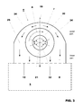
- Figure 3 shows the turbine axis 21 of the turbine along which the steam flow propagates in the expansion stages 2, and the axis 19 along which the steam flow is diverted in the exhaust diffuser 4 to be discharged into the condenser 5.
- Each expansion stage is defined by stator blades and rotor blades.
- the stator blades are fixed to a blade carrier and define a plurality of blade flow guide vanes through which the steam flow passes.
- the rotor blades are assembled to a rotor core and define a plurality of paths (each path is defined between two adjacent rotor blades).
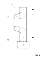
- the diffuser 4 ( figure 6 ) comprises an axial-symmetric portion 7 that gathers the steam coming from the last expansion stage 9, and a non-axial-symmetric collector 8 connected to the neck of the condenser 5.
- the non-axial-symmetric collector 8 comprises an upper part 8a that is made of a quasi-circular or curved casing, and a lower discharging part 8b that has plane walls and is provided with an aperture 10 in communication with the condenser 5.
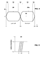
- Figure 2 shows the last expansion stage 9 (i.e. the expansion stage adjacent to the diffuser 4) that comprises the stator blades 13 (in this figure only two stator blades 13 are shown) and downstream of them the rotor blades 13a (in this figure only two rotor blades are shown); arrow F indicates the steam flow global direction.
- stator blades 13 have leading edges 14 and trailing edges 15; moreover each couple of two adjacent stator blades 13 defines the guide vanes 16 having openings 17 that define the smallest passing through cross section of the guide vane.
- stator blades 13 of one of the expansion stages define different openings 17 along the circumference of the turbine.
- stator blades 13 that define different openings 17 are those of the stage adjacent to the diffuser 4.
- the steam turbine has the stator blades 13 according to the invention; these stator blades 13 are followed by rotor blades 13a that are all identical (as in traditional turbines) and, downstream of the rotor blades 13a, the steam turbine has the diffuser 4.
- the reference number 20 indicates the circumferential direction and the reference number 21 indicates the turbine axis.
- stator blades 13 are all the same, in order to define different openings 17 the stator blades 13 have different gauge angles B defined between the turbine axis 21 and an axis 23 perpendicular to the opening 17.
- the stage adjacent to the exhaust diffuser 4 comprises a first group 30 of stator blades having a first gauge angle B1 between the turbine axis 21 and the axis 23, and a second group of stator blades 32 having a second gauge angle B2 between the turbine axis 21 and the axis 23, with the first angle B1 different from the second angle B2.
- first group 30 of stator blades 13 is at the upper zone of the exhaust diffuser 4 and the second group 32 of stator blades is at the lower zone of the exhaust diffuser 4 and the first angle B1 is smaller than the second angle B2, such that the openings 17 between the stator blades 13 of the first group 30 are greater than those between the stator blades 13 of the second group 32.
- first angle B1 may also be greater than the second angle B2, such that the openings 17 between the stator blades 13 of the first group 30 at the upper zone are smaller than those between the stator blades 13 of the second group 32 (lower zone).
- stator blades 13 of the first group 30 are symmetrically arranged about the axis 19 (that is the axis of symmetry of the exhaust diffuser 4) and the stator blades 13 of the second group 32 are also symmetrically arranged about the same axis 19.
- the turbine of the invention also comprises a third groups 34 of stator blades having angles B3, B4 ... between the turbine axis 21 and the axis 23 different from the first and second angles B1, B2 and comprised between the first and the second angles B1, B2.
- the blades of the third groups 34 are placed between the blades of the first and second groups 30, 32 and let the flow be conditioned, to avoid sharp change of conditions.
- the first group of blades 30 comprises blades all having the same angle B1
- the second group 32 of blades comprises blades having all the same angle B2
- the third group 34 of blades comprises blades having angles B3, B4, B5;
- the third group 34 of blades is arranged at both transition zones between the first and second group 30, 32 of blades.
- Figure 4 schematically shows the variation of angle B in the circumferential direction defined by angle A drawn with respect to the horizontal axis 25 (see also figure 3 ).
- the zone defined between 0-180 is the upper part of the turbine, and the zone between 180-360 is the lower part of the turbine.
- This diagram is drawn with respect to a baseline 26 that defines the optimised gauge angle B opt between the turbine axis 21 and the normal 23 to the openings 17 calculated in a traditional way (i.e. for a stator with all the openings 17 being the same); curves 28 and 28a of figure 4 describes the deviation of the angle B from this optimised angle B opt .
- Curve 28 shows the embodiment with angle B1 greater than angle B2 (thus openings 17 are smaller in the upper part than in the lower part) and curve 28a shows a preferred embodiment with angles B1 smaller than angles B2 (and thus openings 17 larger at the upper part than at the lower part).
- the deviation of angles B1 and B2 is preferably the same.
- the deviation of angles B1 and B2 is preferably comprised between 2-5°.
- the overall deviation of the angle B from the B opt is zero.
- angles B are different, the zones inbetween have angles B such that they match with each other.
- Figure 5 shows a diagram indicating the angle B for each blade; in particular figure 5 shows the baseline 26 and the two lines corresponding to angles B1 and B2. Angles B3, B4, B5 are comprised between B1 and B2.
- the steam flow generated by the steam generator 3 enters the expansion stages 2 and delivers mechanical power to the rotor.
- the steam flow is diverted such that a greater amount of flow is driven towards the upper part of the diffuser 4 (i.e. close to the aperture 10 of the diffuser 4) and a smaller amount of steam flow is driven towards the lower part of the diffuser (i.e. close to the collecting zone 7 of the diffuser 4).
- This steam flow distribution lets more uniform operating conditions be achieved and mixing losses and pressure drops at the diffuser be reduced such that an overall increase in efficiency is achieved.
- the present invention also relates to a method for discharging a flow from the axial turbine having a plurality of expansion stages followed by a diffuser for collecting and discharging the flow passing through the expansion stages, wherein the expansion stages 2 and/or the exhaust diffuser 4 have at least a non-axial symmetric portion.
- the method consists in differently driving the flow within the expansion stages according to the angular position along the circumference of the turbine.
Landscapes
- Engineering & Computer Science (AREA)
- Mechanical Engineering (AREA)
- General Engineering & Computer Science (AREA)
- Turbine Rotor Nozzle Sealing (AREA)
Priority Applications (5)
| Application Number | Priority Date | Filing Date | Title |
|---|---|---|---|
| EP09170201A EP2295732A1 (de) | 2009-09-14 | 2009-09-14 | Axialturbine und Verfahren zur Abgabe eines Stroms aus einer Axialturbine |
| DE102010044819.2A DE102010044819B4 (de) | 2009-09-14 | 2010-09-09 | Axialturbine und ein Verfahren zum Abführen eines Stroms von einer Axialturbine |
| US12/880,240 US8506233B2 (en) | 2009-09-14 | 2010-09-13 | Axial turbine and method for discharging a flow from an axial turbine |
| JP2010205726A JP5693112B2 (ja) | 2009-09-14 | 2010-09-14 | 軸流タービン及び軸流タービンから流れを排出するための方法 |
| CN201010530015.0A CN102052090B (zh) | 2009-09-14 | 2010-09-14 | 轴流式涡轮机以及用于从轴流式涡轮机中排出流的方法 |
Applications Claiming Priority (1)
| Application Number | Priority Date | Filing Date | Title |
|---|---|---|---|
| EP09170201A EP2295732A1 (de) | 2009-09-14 | 2009-09-14 | Axialturbine und Verfahren zur Abgabe eines Stroms aus einer Axialturbine |
Publications (1)
| Publication Number | Publication Date |
|---|---|
| EP2295732A1 true EP2295732A1 (de) | 2011-03-16 |
Family
ID=41795360
Family Applications (1)
| Application Number | Title | Priority Date | Filing Date |
|---|---|---|---|
| EP09170201A Withdrawn EP2295732A1 (de) | 2009-09-14 | 2009-09-14 | Axialturbine und Verfahren zur Abgabe eines Stroms aus einer Axialturbine |
Country Status (5)
| Country | Link |
|---|---|
| US (1) | US8506233B2 (de) |
| EP (1) | EP2295732A1 (de) |
| JP (1) | JP5693112B2 (de) |
| CN (1) | CN102052090B (de) |
| DE (1) | DE102010044819B4 (de) |
Families Citing this family (4)
| Publication number | Priority date | Publication date | Assignee | Title |
|---|---|---|---|---|
| FR2975451B1 (fr) * | 2011-05-16 | 2016-07-01 | Turbomeca | Procede de soufflage dans un diffuseur de turbine a gaz et diffuseur correspondant |
| US9644497B2 (en) * | 2013-11-22 | 2017-05-09 | Siemens Energy, Inc. | Industrial gas turbine exhaust system with splined profile tail cone |
| CN113757133B (zh) * | 2021-07-27 | 2024-05-14 | 无锡曲速智能科技有限公司 | 高效率内转子电机驱动的双进口多翼风机及其设计方法 |
| US11994041B2 (en) | 2021-10-04 | 2024-05-28 | General Electric Company | Advanced aero diffusers for turbine frames and outlet guide vanes |
Citations (4)
| Publication number | Priority date | Publication date | Assignee | Title |
|---|---|---|---|---|
| GB191111890A (de) * | ||||
| US1697174A (en) * | 1923-08-16 | 1929-01-01 | Bbc Brown Boveri & Cie | Steam-turbine stage |
| DE1935534U (de) * | 1963-11-29 | 1966-03-31 | Bristol Siddeley Engines Ltd | Axialturbine oder -verdichter mit einstellbaren endleitschaufeln. |
| EP0690206A2 (de) * | 1994-06-29 | 1996-01-03 | ABB Management AG | Diffusor für Turbomaschine |
Family Cites Families (21)
| Publication number | Priority date | Publication date | Assignee | Title |
|---|---|---|---|---|
| DE317364C (de) * | 1916-09-28 | |||
| US1534721A (en) * | 1924-04-28 | 1925-04-21 | Aeg | Construction of elastic-fluid turbines to prevent breakage of blades due to vibrations |
| US1679174A (en) | 1927-03-12 | 1928-07-31 | Edwin H Richards | Body-punch resistance developer |
| CH361081A (de) | 1957-04-29 | 1962-03-31 | Gen Electric | Mehrstufiger Axialkompressor |
| US3169747A (en) * | 1961-01-06 | 1965-02-16 | Bristol Siddeley Engines Ltd | Rotary bladed power conversion machines |
| US3285568A (en) * | 1965-03-17 | 1966-11-15 | Biach Ind | Tensioning apparatus |
| DE1935534A1 (de) | 1969-07-12 | 1971-02-18 | Robel & Co G | Vorrichtung fuer Gleisbaumaschinen |
| JPS5435503A (en) * | 1977-08-24 | 1979-03-15 | Toshiba Corp | Nozzle of steam turbine |
| JPH02119602A (ja) * | 1988-10-28 | 1990-05-07 | Hitachi Ltd | タービン排気室 |
| US5518366A (en) * | 1994-06-13 | 1996-05-21 | Westinghouse Electric Corporation | Exhaust system for a turbomachine |
| JPH0849501A (ja) * | 1994-08-10 | 1996-02-20 | Mitsubishi Heavy Ind Ltd | 蒸気タービン |
| FR2742799B1 (fr) | 1995-12-20 | 1998-01-16 | Snecma | Palier d'extremite interne d'aube pivotante |
| JP3772019B2 (ja) * | 1998-04-21 | 2006-05-10 | 株式会社東芝 | 蒸気タービン |
| US6439838B1 (en) | 1999-12-18 | 2002-08-27 | General Electric Company | Periodic stator airfoils |
| DE10037684A1 (de) | 2000-07-31 | 2002-02-14 | Alstom Power Nv | Niederdruckdampfturbine mit Mehrkanal-Diffusor |
| JP2004100553A (ja) * | 2002-09-09 | 2004-04-02 | Mitsubishi Heavy Ind Ltd | 回転機械の静翼構造 |
| EP1561911A1 (de) | 2004-02-06 | 2005-08-10 | Siemens Aktiengesellschaft | Dampfturbine mit Anzapfung im Profilabschnitt der Leitschaufel |
| US20070081892A1 (en) * | 2005-10-06 | 2007-04-12 | General Electric Company | Steam turbine exhaust diffuser |
| US7743497B2 (en) | 2005-10-06 | 2010-06-29 | General Electric Company | Method of providing non-uniform stator vane spacing in a compressor |
| EP1892384A1 (de) | 2006-08-25 | 2008-02-27 | Siemens Aktiengesellschaft | Diffusor für eine Dampfturbine |
| EP2080871A1 (de) | 2008-01-15 | 2009-07-22 | ABB Turbo Systems AG | Leitvorrichtung für Schaufelverstellung |
-
2009
- 2009-09-14 EP EP09170201A patent/EP2295732A1/de not_active Withdrawn
-
2010
- 2010-09-09 DE DE102010044819.2A patent/DE102010044819B4/de active Active
- 2010-09-13 US US12/880,240 patent/US8506233B2/en active Active
- 2010-09-14 CN CN201010530015.0A patent/CN102052090B/zh active Active
- 2010-09-14 JP JP2010205726A patent/JP5693112B2/ja active Active
Patent Citations (4)
| Publication number | Priority date | Publication date | Assignee | Title |
|---|---|---|---|---|
| GB191111890A (de) * | ||||
| US1697174A (en) * | 1923-08-16 | 1929-01-01 | Bbc Brown Boveri & Cie | Steam-turbine stage |
| DE1935534U (de) * | 1963-11-29 | 1966-03-31 | Bristol Siddeley Engines Ltd | Axialturbine oder -verdichter mit einstellbaren endleitschaufeln. |
| EP0690206A2 (de) * | 1994-06-29 | 1996-01-03 | ABB Management AG | Diffusor für Turbomaschine |
Also Published As
| Publication number | Publication date |
|---|---|
| US20110064560A1 (en) | 2011-03-17 |
| US8506233B2 (en) | 2013-08-13 |
| DE102010044819B4 (de) | 2022-12-15 |
| JP2011058498A (ja) | 2011-03-24 |
| DE102010044819A1 (de) | 2011-03-17 |
| CN102052090B (zh) | 2015-08-12 |
| CN102052090A (zh) | 2011-05-11 |
| JP5693112B2 (ja) | 2015-04-01 |
Similar Documents
| Publication | Publication Date | Title |
|---|---|---|
| CA2849651C (en) | Axial turbomachine stator with ailerons at the blade roots | |
| EP2256299B1 (de) | Deflektor für eine Gasturbinenstreben- und -schaufelanordnung | |
| US20110110763A1 (en) | Exhaust Ring and Method to Reduce Turbine Acoustic Signature | |
| US8100657B2 (en) | Steam turbine rotating blade for a low pressure section of a steam turbine engine | |
| CN101769174B (zh) | 用于减小喷嘴应力的方法和装置 | |
| EP2204534B1 (de) | Synchronisierung von Gasturbinenschaufeln | |
| CN101403321A (zh) | 轴流式涡轮机以及轴流式涡轮机级结构 | |
| EP2554793B1 (de) | Zwischenturbinenkanäle mit Leitschaufeln von einer Gasturbinentriebwerk | |
| KR20100080427A (ko) | 터빈 엔진용 인듀서와 관련된 방법, 시스템 및/또는 장치 | |
| US8057187B2 (en) | Steam turbine rotating blade for a low pressure section of a steam turbine engine | |
| EP2295732A1 (de) | Axialturbine und Verfahren zur Abgabe eines Stroms aus einer Axialturbine | |
| CN101672199A (zh) | 用于蒸汽轮机发动机的低压段的蒸汽轮机旋转叶片 | |
| CN110418896B (zh) | 回引级和径流式涡轮流体能量机械 | |
| JP5583493B2 (ja) | 回転機械を組み立てるための方法及び装置 | |
| EP2730752A2 (de) | System und Verfahren zur Verbesserung der Gasturbinenleistung bei Teillastbetrieb | |
| US8322972B2 (en) | Steampath flow separation reduction system | |
| CN107435656B (zh) | 安装在推进器上的涡旋扰流器 | |
| US8545170B2 (en) | Turbo machine efficiency equalizer system | |
| EP3020951B1 (de) | Gasturbinenmotorkanal mit profiliertem bereich | |
| EP2666963B1 (de) | Turbine und Verfahren zur Verminderung von Stoßverlusten in einer Turbine | |
| EP2677123B2 (de) | Diffusor für Turbomaschinen | |
| US11401835B2 (en) | Turbine center frame | |
| US20200011182A1 (en) | Method for modifying a turbine | |
| EP2299057A1 (de) | Gasturbine | |
| EP2161413A2 (de) | Dampfturbinendrehschaufel für einen Niederdruckabschnitt eines Dampfturbinenmotors |
Legal Events
| Date | Code | Title | Description |
|---|---|---|---|
| PUAI | Public reference made under article 153(3) epc to a published international application that has entered the european phase |
Free format text: ORIGINAL CODE: 0009012 |
|
| AK | Designated contracting states |
Kind code of ref document: A1 Designated state(s): AT BE BG CH CY CZ DE DK EE ES FI FR GB GR HR HU IE IS IT LI LT LU LV MC MK MT NL NO PL PT RO SE SI SK SM TR |
|
| STAA | Information on the status of an ep patent application or granted ep patent |
Free format text: STATUS: THE APPLICATION IS DEEMED TO BE WITHDRAWN |
|
| 18D | Application deemed to be withdrawn |
Effective date: 20110917 |