EP2256299B1 - Deflektor für eine Gasturbinenstreben- und -schaufelanordnung - Google Patents
Deflektor für eine Gasturbinenstreben- und -schaufelanordnung Download PDFInfo
- Publication number
- EP2256299B1 EP2256299B1 EP10250678.9A EP10250678A EP2256299B1 EP 2256299 B1 EP2256299 B1 EP 2256299B1 EP 10250678 A EP10250678 A EP 10250678A EP 2256299 B1 EP2256299 B1 EP 2256299B1
- Authority
- EP
- European Patent Office
- Prior art keywords
- strut
- vanes
- deflectors
- struts
- assembly
- Prior art date
- Legal status (The legal status is an assumption and is not a legal conclusion. Google has not performed a legal analysis and makes no representation as to the accuracy of the status listed.)
- Active
Links
Images


Classifications
-
- F—MECHANICAL ENGINEERING; LIGHTING; HEATING; WEAPONS; BLASTING
- F01—MACHINES OR ENGINES IN GENERAL; ENGINE PLANTS IN GENERAL; STEAM ENGINES
- F01D—NON-POSITIVE DISPLACEMENT MACHINES OR ENGINES, e.g. STEAM TURBINES
- F01D25/00—Component parts, details, or accessories, not provided for in, or of interest apart from, other groups
- F01D25/08—Cooling; Heating; Heat-insulation
- F01D25/14—Casings modified therefor
-
- F—MECHANICAL ENGINEERING; LIGHTING; HEATING; WEAPONS; BLASTING
- F01—MACHINES OR ENGINES IN GENERAL; ENGINE PLANTS IN GENERAL; STEAM ENGINES
- F01D—NON-POSITIVE DISPLACEMENT MACHINES OR ENGINES, e.g. STEAM TURBINES
- F01D17/00—Regulating or controlling by varying flow
- F01D17/10—Final actuators
- F01D17/12—Final actuators arranged in stator parts
- F01D17/14—Final actuators arranged in stator parts varying effective cross-sectional area of nozzles or guide conduits
- F01D17/141—Final actuators arranged in stator parts varying effective cross-sectional area of nozzles or guide conduits by means of shiftable members or valves obturating part of the flow path
- F01D17/143—Final actuators arranged in stator parts varying effective cross-sectional area of nozzles or guide conduits by means of shiftable members or valves obturating part of the flow path the shiftable member being a wall, or part thereof of a radial diffuser
-
- F—MECHANICAL ENGINEERING; LIGHTING; HEATING; WEAPONS; BLASTING
- F01—MACHINES OR ENGINES IN GENERAL; ENGINE PLANTS IN GENERAL; STEAM ENGINES
- F01D—NON-POSITIVE DISPLACEMENT MACHINES OR ENGINES, e.g. STEAM TURBINES
- F01D25/00—Component parts, details, or accessories, not provided for in, or of interest apart from, other groups
- F01D25/16—Arrangement of bearings; Supporting or mounting bearings in casings
-
- F—MECHANICAL ENGINEERING; LIGHTING; HEATING; WEAPONS; BLASTING
- F01—MACHINES OR ENGINES IN GENERAL; ENGINE PLANTS IN GENERAL; STEAM ENGINES
- F01D—NON-POSITIVE DISPLACEMENT MACHINES OR ENGINES, e.g. STEAM TURBINES
- F01D25/00—Component parts, details, or accessories, not provided for in, or of interest apart from, other groups
- F01D25/24—Casings; Casing parts, e.g. diaphragms, casing fastenings
-
- F—MECHANICAL ENGINEERING; LIGHTING; HEATING; WEAPONS; BLASTING
- F01—MACHINES OR ENGINES IN GENERAL; ENGINE PLANTS IN GENERAL; STEAM ENGINES
- F01D—NON-POSITIVE DISPLACEMENT MACHINES OR ENGINES, e.g. STEAM TURBINES
- F01D25/00—Component parts, details, or accessories, not provided for in, or of interest apart from, other groups
- F01D25/28—Supporting or mounting arrangements, e.g. for turbine casing
-
- F—MECHANICAL ENGINEERING; LIGHTING; HEATING; WEAPONS; BLASTING
- F01—MACHINES OR ENGINES IN GENERAL; ENGINE PLANTS IN GENERAL; STEAM ENGINES
- F01D—NON-POSITIVE DISPLACEMENT MACHINES OR ENGINES, e.g. STEAM TURBINES
- F01D5/00—Blades; Blade-carrying members; Heating, heat-insulating, cooling or antivibration means on the blades or the members
- F01D5/12—Blades
- F01D5/14—Form or construction
- F01D5/141—Shape, i.e. outer, aerodynamic form
- F01D5/142—Shape, i.e. outer, aerodynamic form of the blades of successive rotor or stator blade-rows
-
- F—MECHANICAL ENGINEERING; LIGHTING; HEATING; WEAPONS; BLASTING
- F01—MACHINES OR ENGINES IN GENERAL; ENGINE PLANTS IN GENERAL; STEAM ENGINES
- F01D—NON-POSITIVE DISPLACEMENT MACHINES OR ENGINES, e.g. STEAM TURBINES
- F01D5/00—Blades; Blade-carrying members; Heating, heat-insulating, cooling or antivibration means on the blades or the members
- F01D5/12—Blades
- F01D5/14—Form or construction
- F01D5/141—Shape, i.e. outer, aerodynamic form
- F01D5/142—Shape, i.e. outer, aerodynamic form of the blades of successive rotor or stator blade-rows
- F01D5/143—Contour of the outer or inner working fluid flow path wall, i.e. shroud or hub contour
-
- F—MECHANICAL ENGINEERING; LIGHTING; HEATING; WEAPONS; BLASTING
- F01—MACHINES OR ENGINES IN GENERAL; ENGINE PLANTS IN GENERAL; STEAM ENGINES
- F01D—NON-POSITIVE DISPLACEMENT MACHINES OR ENGINES, e.g. STEAM TURBINES
- F01D5/00—Blades; Blade-carrying members; Heating, heat-insulating, cooling or antivibration means on the blades or the members
- F01D5/12—Blades
- F01D5/14—Form or construction
- F01D5/141—Shape, i.e. outer, aerodynamic form
- F01D5/146—Shape, i.e. outer, aerodynamic form of blades with tandem configuration, split blades or slotted blades
-
- F—MECHANICAL ENGINEERING; LIGHTING; HEATING; WEAPONS; BLASTING
- F01—MACHINES OR ENGINES IN GENERAL; ENGINE PLANTS IN GENERAL; STEAM ENGINES
- F01D—NON-POSITIVE DISPLACEMENT MACHINES OR ENGINES, e.g. STEAM TURBINES
- F01D9/00—Stators
- F01D9/02—Nozzles; Nozzle boxes; Stator blades; Guide conduits, e.g. individual nozzles
-
- F—MECHANICAL ENGINEERING; LIGHTING; HEATING; WEAPONS; BLASTING
- F01—MACHINES OR ENGINES IN GENERAL; ENGINE PLANTS IN GENERAL; STEAM ENGINES
- F01D—NON-POSITIVE DISPLACEMENT MACHINES OR ENGINES, e.g. STEAM TURBINES
- F01D9/00—Stators
- F01D9/02—Nozzles; Nozzle boxes; Stator blades; Guide conduits, e.g. individual nozzles
- F01D9/04—Nozzles; Nozzle boxes; Stator blades; Guide conduits, e.g. individual nozzles forming ring or sector
- F01D9/041—Nozzles; Nozzle boxes; Stator blades; Guide conduits, e.g. individual nozzles forming ring or sector using blades
-
- F—MECHANICAL ENGINEERING; LIGHTING; HEATING; WEAPONS; BLASTING
- F01—MACHINES OR ENGINES IN GENERAL; ENGINE PLANTS IN GENERAL; STEAM ENGINES
- F01D—NON-POSITIVE DISPLACEMENT MACHINES OR ENGINES, e.g. STEAM TURBINES
- F01D9/00—Stators
- F01D9/06—Fluid supply conduits to nozzles or the like
-
- F—MECHANICAL ENGINEERING; LIGHTING; HEATING; WEAPONS; BLASTING
- F02—COMBUSTION ENGINES; HOT-GAS OR COMBUSTION-PRODUCT ENGINE PLANTS
- F02C—GAS-TURBINE PLANTS; AIR INTAKES FOR JET-PROPULSION PLANTS; CONTROLLING FUEL SUPPLY IN AIR-BREATHING JET-PROPULSION PLANTS
- F02C7/00—Features, components parts, details or accessories, not provided for in, or of interest apart form groups F02C1/00 - F02C6/00; Air intakes for jet-propulsion plants
- F02C7/04—Air intakes for gas-turbine plants or jet-propulsion plants
- F02C7/057—Control or regulation
-
- F—MECHANICAL ENGINEERING; LIGHTING; HEATING; WEAPONS; BLASTING
- F02—COMBUSTION ENGINES; HOT-GAS OR COMBUSTION-PRODUCT ENGINE PLANTS
- F02C—GAS-TURBINE PLANTS; AIR INTAKES FOR JET-PROPULSION PLANTS; CONTROLLING FUEL SUPPLY IN AIR-BREATHING JET-PROPULSION PLANTS
- F02C9/00—Controlling gas-turbine plants; Controlling fuel supply in air- breathing jet-propulsion plants
- F02C9/16—Control of working fluid flow
- F02C9/20—Control of working fluid flow by throttling; by adjusting vanes
- F02C9/22—Control of working fluid flow by throttling; by adjusting vanes by adjusting turbine vanes
-
- F—MECHANICAL ENGINEERING; LIGHTING; HEATING; WEAPONS; BLASTING
- F04—POSITIVE - DISPLACEMENT MACHINES FOR LIQUIDS; PUMPS FOR LIQUIDS OR ELASTIC FLUIDS
- F04D—NON-POSITIVE-DISPLACEMENT PUMPS
- F04D29/00—Details, component parts, or accessories
- F04D29/40—Casings; Connections of working fluid
- F04D29/52—Casings; Connections of working fluid for axial pumps
- F04D29/54—Fluid-guiding means, e.g. diffusers
- F04D29/541—Specially adapted for elastic fluid pumps
- F04D29/542—Bladed diffusers
- F04D29/544—Blade shapes
Definitions
- the application relates generally to gas turbine engines, and more particularly, to a deflector for a strut and vane assembly.
- Gas turbine engine ducts may have structural struts in the gas path flow, as well as stationary airfoil vanes which guide combustion gases through the duct.
- the structural struts are typically larger in cross-section than the vanes, and the struts may tend to cause flow separation, particularly when in close proximity to the vanes, which is undesirable.
- this problem is addressed by axially spacing the struts apart from the vanes to avoid flow separation, which can result in a longer engine configuration.
- GB 2226600 discloses a vane assembly and gas turbine engine having the features of the preamble of claims 1 and 8. Further vane assemblies of the prior art are disclosed in E1621733 , GB 220013 , GB 628263 and EP 0343888 .
- a vane assembly providing a section of an annular duct of a gas turbine engine for directing a fluid flow therethrough, the assembly comprising inner and outer duct walls, a plurality of strut fairings, aerodynamic vanes and aerodynamic deflectors each extending radially between the inner and outer duct walls, each of the strut fairings having a circumferential width dimension greater than a circumferential width dimension of the respective vanes, leading edges of the deflectors positioned upstream of leading edges of the vanes and downstream of leading edge of the strut fairings with respect to the fluid flow through the duct, a said deflector being positioned circumferentially between at least one said strut fairing and an adjacent vane.
- a gas turbine engine comprising an annular gas path duct having an inner duct wall and an outer duct wall, the gas path duct having: a plurality of struts extending radially between the inner duct wall and the outer duct wall, the struts having an aerodynamic shape; a plurality of airfoil vanes located circumferentially around the duct, the vanes extending radially between the inner duct wall and the outer duct wall, the vanes having leading edges disposed downstream of leading edges of the struts relative to a direction of gas flow through the engine; a plurality of aerodynamic deflectors extending radially between the inner duct wall and the outer duct wall, the deflectors located circumferentially around the duct, a said aerodynamic deflector being circumferentially located between a said strut and an adjacent said vane; and wherein the leading edges of the struts define a first radially extending plane and the leading edges of the vanes define
- a method of channelling an axial gas flow between a strut and adjacent vane of a circumferential array of vanes in a gas turbine engine, the strut having a leading edge upstream of leading edges of the vanes with respect to the axial flow comprising: (a) determining an axial location at which a flow separation substantially caused by the strut would occur; and (b) providing at least one deflector having an aerodynamic profile, positioned circumferentially between the strut and the adjacent one of the vanes, the deflector having a leading edge upstream of the axial point and a trailing edge downstream of the axial point, the deflector thereby extending axially through the axial location, such that in use the axial gas flow through the engine passing the struts will be guided by the deflectors so as to substantially impede flow separation around the strut.
- Step (a) may be conducted at both pressure and suction sides of the struts, a deflector being
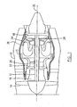
- a bypass gas turbine engine has an engine axis 32 and includes a housing or nacelle 10, a casing 13, a low pressure spool assembly which includes a fan assembly 14, a low pressure compressor assembly 16 and a low pressure turbine assembly 18 connected by a shaft 12, and a high pressure spool assembly which includes a high pressure compressor assembly 22 and a high pressure turbine assembly 24 connected by a turbine shaft 20.
- the core casing 13 surrounds the low and high pressure spool assemblies to define a main fluid path there through.
- a combustor 26 to generate combustion gases to power the high pressure turbine assembly 24 and the low pressure turbine assembly 18.
- a mid turbine frame system 28 is disposed between the high pressure turbine assembly 24 and the low pressure turbine assembly 18.
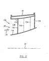
- the mid turbine frame (MTF) system 28 includes an annular outer case 30 (see FIG. 2 ) which has mounting flanges (not numbered) at both ends for connection to the core casing 13 of the engine.
- the outer case 30 may be a part of the core casing 13.
- the MTF system 28 includes a strut and vane ring assembly 110 which is supported within the annular outer case 30, for directing a gas flow 34 from the high pressure turbine assembly 24 therethrough to the low pressure turbine assembly 18.
- the strut and vane ring assembly 110 includes annular outer and inner duct walls 114 and 116 defining a gas path duct 136 for directing the gas flow 34.
- a plurality of circumferentially spaced structural struts (only one shown) 118 extend radially between the outer and inner duct walls 114, 116.
- the structural struts 118 have an aerodynamic shape in cross-section forming a fairing with leading edges 112 and trailing edges 119 relative to the gas flow 34 direction.
- a plurality of airfoil vanes 134 are located circumferentially around and axially at a rear end of the gas path duct 136 and extend radially between the outer and inner duct walls 114, 116.
- the airfoil vanes 134 have leading edges 133 and trailing edges 135 relative to the gas flow 34 direction.
- the leading edges 133 of the airfoil vanes 134 are disposed downstream of leading edges 112 of the structural struts 118 relative to a direction of the gas flow 34.
- the structural struts 118 each have a circumferential dimension much greater than the circumferential dimension of the airfoil vanes 134, for example, at least double the thickness.
- the airfoil vanes 134 generally form vane nozzles (not numbered) for directing the gas flow 34 when the gas flow 34 exits the gas path duct 136.
- the structural struts 118 substantially transfer loads and may have a hollow structure to allow support components and oil service lines to pass therethrough.
- a plurality of aerodynamic deflectors 150 extend radially between the outer and inner duct walls 114, 116 and are located around the gas path duct 136.
- deflectors 150 may include first and second groups of deflectors 150a and 150b, (only one of each group is shown in FIG. 3 ).
- Deflectors 150a and 150b have leading edges 149a and 149b respectively, and trailing edges 151a and 151b respectively, relative to the gas flow 34.
- Each deflector 150a and 150b is located circumferentially between an adjacent strut 118 and an adjacent vane 134.
- Deflector 150a is positioned at the pressure side of the strut 118 and deflector 150b is positioned at the suction side the strut 118. It should be noted that airfoil vanes 134 are used to form an array of vane nozzles (not numbered) for directing the gas flow 34 when exiting the gas path duct 136. The presence of the deflectors 150a, 150b reduces pressure variation at an exit of the annular gas path duct 136, thereby improving the dynamics of blades located downstream of the strut and vane ring assembly 110, for example, the rotor of the low pressure turbine assembly 18.
- Line 36a represents a radially extending plane defined by the leading edges 112 of the struts 118.
- Line 36b represents a radially extending plane defined by the leading edges 133 of the vanes 134.
- Line 36c represents a radially extending plane defined by the trailing edges 135, 151a and 151b of the respective vanes 134 and deflectors such as 150a, 150b.
- Each of the struts 118 is incorporated with one of the vanes 134 and thus the trailing edges 119 of the struts are also on the plane represented by line 36c.
- the leading edges 149a and 149b of the respective deflectors 150a and 150b are axially positioned between lines 36a and 36b.
- the deflectors 150a and 150b are thereby used to intercept flow separation which may be substantially caused by the strut 118.
- lines 152a and 152b represent two series of axial points along the circumferential direction at the respective pressure and suction sides of the strut 118, at which flow separation substantially caused by the strut 118, would occur if deflectors 150a and 150b were not in place.
- the deflectors 150a and 150b may extend across the respective lines 152a and 152b thereby more effectively intercepting a flow stream of the flow separation at the axial points represented by lines 152a and 152b.
- deflector 150a which is positioned at the pressure side of the strut 118, extends further upstream relative to the gas flow 34 direction, than the deflector 150b which is positioned at the suction side of the strut 118, because the flow separation substantially caused by the strut 118 at the pressure side thereof would occur in a more upstream location than the flow separation at the suction side of the strut 118, as shown by the lines 152a and 152b.
- the deflectors 150a and 150b are positioned substantially circumferentially mid way between the adjacent struts 118 and the airfoil vane 134.
- the trailing edges 119, 135 and 151a, 151b of the respective struts 118, vanes 134 and deflectors 150a and 150b have a substantially same shape, thereby defining substantially equal throat areas of the vane nozzles formed by the strut and vane ring assembly 110.
- a throat area of the vane nozzles is a smallest annulus area between two adjacent airfoils as shown in FIG. 3 and indicated by letter "T".
- the throat areas in combination form a metering exit area of the strut and vane ring assembly 110 for the gas flow 34, and control the engine rotor speed by increasing or reducing this metering exit area.
- the MTF system 28 of the gas turbine engine includes a strut and vane ring assembly 110' which is formed with a separate strut ring (not numbered) and vane ring (not numbered) according to another embodiment, in contrast to the strut and vane ring assembly 110 of FIGS. 2 and 3 in which structural struts 118 are incorporated into the vane ring.
- Components and features of the strut and vane ring assembly 110' of FIGS. 4 and 5 which are similar to those of the strut and vane ring assembly 110 of FIGS. 2 and 3 are indicated by similar numerals and will not be redundantly described herein.
- the following description of strut and vane ring assembly 110' will be focussed on the structures thereof which are different from the strut and vane ring assembly 110 of FIGS. 2 and 3 .
- the strut and vane ring assembly 110' includes outer and inner duct walls 114, 116 to define the gas path duct 136 therebetween, and may be supported within the outer casing 30 of FIG. 2 (not shown in this embodiment).
- the outer and inner duct walls 114, 116 include respective front sections 114a, 116a to form the strut ring, and rear sections 114b and 116b to form the vane ring.
- Struts 118 radially extend between the front section 114a, 116a of the respective outer and inner duct walls 114, 116 and vanes 134 radially extend between the rear sections 114b and 116b of the respective outer and inner duct walls 114, 116.
- the strut ring and the vane ring are connected together for example, by welding the front section 114a and rear section 114b of the outer duct wall 114 and by welding together front section 116a and rear section 116b of the inner duct wall 116.
- Struts 118 are not incorporated with any one of the vanes 134 and the deflectors 150 such as 150a, 150b (shown in FIG. 5 ) radially extend between the front section 114a of the outer duct wall 114 and the front section 116a of the inner duct wall 116 and do not axially extend into the vane ring defined by the rear section 114b, 116b.
- lines 36a and 36b in FIG. 5 represent radially extending planes defined by the respective leading edges 112 of the struts 118 and leading edges 133 of the vanes 134.
- line 36d of FIG. 5 represents a radially extending plane defined by the trailing edges 119 of the struts 118 and the trailing edges 151 a, 151 b of the deflectors 150a, 150b
- line 36e of FIG. 5 represents a radially extending plane defined by the trailing edges 135 of the vanes 134.
- the leading edges 149a, 149b of the deflectors 150a, 150b are axially positioned between lines 36a and 36b while line 36b is axially positioned downstream of line 36d relative to the direction of the gas flow 34.
- vanes 134 are circumferential evenly spaced one from another in order to define substantially equal throat areas T therebetween for the vane nozzles of the assembly 110'.
- deflectors 150a, 150b may be spaced apart from the respective pressure and suction sides of the strut 118 in order to define throat areas between the strut 118 and the respective deflectors 150a, 150b which are substantially equal to the throat area T of the vanes 134.
- deflectors 150a and 150b in both embodiments shown in FIGS. 3 and 5 have an aerodynamic profile in a cross-section, substantially contouring the shapes of the respective pressure and suction sides of strut 118.
Landscapes
- Engineering & Computer Science (AREA)
- Mechanical Engineering (AREA)
- General Engineering & Computer Science (AREA)
- Physics & Mathematics (AREA)
- Fluid Mechanics (AREA)
- Chemical & Material Sciences (AREA)
- Combustion & Propulsion (AREA)
- Geometry (AREA)
- Turbine Rotor Nozzle Sealing (AREA)
Claims (15)
- Schaufelbaugruppe (110; 110'), die einen Abschnitt eines ringförmigen Durchlass (136) eines Gasturbinenmotors bereitstellt, um einen Fluidstrom dadurch hindurch zu lenken, wobei die Baugruppe eine innere und eine äußere Durchlasswand (116, 114), eine Mehrzahl von Streben oder Strebenverkleidungen (118) und aerodynamische Schaufeln (134) umfasst, dadurch gekennzeichnet, dass sie ferner aerodynamische Lenkplatten (150) umfasst, die sich jeweils radial zwischen der inneren und der äußeren Durchlasswand (116, 114) erstrecken, wobei jede der Streben oder Strebenverkleidungen (118) eine Umfangsbreitenabmessung aufweist, die größer als eine Umfangsbreitenabmessung der jeweiligen Schaufeln (134) ist, wobei Vorderkanten (149) der Lenkplatten (150) in Bezug auf den Fluidstrom durch den Durchlass stromaufwärts von Vorderkanten (133) der Schaufeln (134) und stromabwärts der Vorderkante (112) der Streben oder Strebenverkleidungen (118) angeordnet sind, wobei die Lenkplatte (150) in Umfangsrichtung zwischen wenigstens einer Strebe oder Strebenverkleidung (118) und einer benachbarten Schaufel (134) angeordnet ist.
- Baugruppe nach Anspruch 1 wobei jede der Streben oder Strebenverkleidungen (118) einstückig mit einer der Schaufeln (134) gebildet ist.
- Baugruppe nach Anspruch 2, wobei die Vorderkanten (149) der Lenkplatten (150) axial an Hinterkanten (135) der Schaufeln (134) ausgerichtet sind, wodurch eine Mehrzahl von Schaufeldüsen mit im Wesentlichen gleichen Halsbereichen gebildet wird.
- Baugruppe nach einem der vorangehenden Ansprüche, wobei die Vorderkante (149) jeder Lenkplatte (150) stromaufwärts von einem axialen Punkt ist, an dem die Strömungsaufteilung, die im Wesentlichen von der benachbarten Strebe oder Strebenverkleidung (118) verursacht wird, stattfinden würde, wenn die Lenkplatte nicht vorhanden wäre.
- Baugruppe nach einem der vorangehenden Ansprüche, wobei jede der Lenkplatten (150) in Umfangsrichtung in der Mitte zwischen einer der Streben oder Strebenverkleidungen (118) und einer der Schaufeln (134) angeordnet ist.
- Baugruppe nach einem der vorangehenden Ansprüche, wobei die Lenkplatten eine erste Gruppe der Lenkplatten umfassen, wobei jede Lenkplatte (150a) der ersten Gruppe von Lenkplatten auf einer Druckseite von einer der Streben oder Strebenverkleidungen (118) angeordnet ist und ein aerodynamisches Profil in einem Querschnitt aufweist, das im Wesentlichen derart konturiert ist, dass es einer Form der Druckseite der Streben oder Strebenverkleidungen (118) entspricht.
- Baugruppe nach einem der vorangehenden Ansprüche, wobei die Lenkplatten eine zweite Gruppe der Lenkplatten umfassen, wobei jede Lenkplatte (150b) der zweiten Gruppe von Lenkplatten auf einer Ansaugseite von einer der Streben oder Strebenverkleidungen (118) angeordnet ist und ein aerodynamisches Profil in einem Querschnitt aufweist, das im Wesentlichen derart konturiert ist, dass es einer der Ansaugseite der Streben oder Strebenverkleidungen (118) entspricht.
- Gasturbinenmotor, umfassend einen ringförmigen Gasdurchlass (136) mit einer inneren Durchlasswand (116) und einer äußeren Durchlasswand (114), wobei der Gasdurchlass Folgendes aufweist:eine Mehrzahl von Streben (118), die sich radial zwischen der inneren Durchlasswand (116) und der äußeren Durchlasswand (114) erstreckt, wobei die Streben (118) eine aerodynamische Form aufweisen; undeine Mehrzahl von Schaufelblättern (134), die in Umfangsrichtung um den Durchlass angeordnet ist, wobei sich die Schaufeln (134) radial zwischen der inneren Durchlasswand (116) und der äußeren Durchlasswand (114) erstrecken, wobei die Schaufeln (134) Vorderkanten (133) aufweisen, die relativ zu einer Richtung des Gasstroms durch den Motor stromabwärts von Vorderkanten (112) der Streben angeordnet sind;wobei die Vorderkanten (112) der Streben (118) eine erste sich radial erstreckenden Ebene (36a) definieren und die Vorderkanten (133) der Schaufeln (134) eine zweite sich radial erstreckenden Ebene (36b) definieren;dadurch gekennzeichnet, dass er ferner Folgendes umfasst:eine Mehrzahl von aerodynamischen Lenkplatten (150), die sich radial zwischen der inneren Durchlasswand (116) und der äußeren Durchlasswand (114) erstrecken, wobei die Lenkplatten (150) in Umfangsrichtung um den Durchlass (136) angeordnet sind, wobei eine aerodynamische Lenkplatte (150) in Umfangsrichtung zwischen einer Strebe (118) und einer benachbarten Schaufel (134) angeordnet ist; undwobei Vorderkanten (149) der aerodynamischen Lenkplatten (150) axial zwischen der ersten und zweiten Ebene (36a, 36b) angeordnet sind.
- Gasturbinenmotor oder Baugruppe nach einem der vorangehenden Ansprüche wobei Hinterkanten der jeweiligen Streben (118), Lenkplatten (150) und Schaufeln (134) eine sich radial erstreckende Ebene (36c) definieren.
- Gasturbinenmotor oder Baugruppe nach einem der Ansprüche 1 bis 8 wobei Hinterkanten (119,151) der jeweiligen Streben (118) und Lenkplatten (150) eine sich radial erstreckende Ebene (36d) definieren und wobei die Hinterkanten (135) der Schaufeln (134) eine weitere sich radial erstreckende Ebene (36e) stromabwärts der sich radial erstreckenden Ebene (36d) definieren, wobei die Vorderkanten (133) der Schaufeln (134) wahlweise stromabwärts der sich radial erstreckenden Ebene (36d) angeordnet sind.
- Gasturbinenmotor oder Baugruppe nach einem der vorangehenden Ansprüche, wobei die Hinterkanten (119) der Lenkplatten (150) die gleiche Form wie die Hinterkanten (135) der Schaufeln (134) aufweisen.
- Gasturbinenmotor oder Baugruppe nach einem der vorangehenden Ansprüche, wobei der Gasdurchlass (136) eine Mehrzahl von im Wesentlichen gleichen Halsbereichen (T) zwischen benachbarten Streben (118), Lenkplatten (150) und Schaufeln (134) definiert, einschließlich Strebe-zu-Lenkplatte-, Lenkplatte-zu-Schaufel und Schaufel-zu-Schaufel-Halsbereichen.
- Gasturbinenmotor oder Baugruppe nach einem der vorangehenden Ansprüche wobei eine Lenkplatte (150a), die auf einer Druckseite einer benachbarten Strebe (118) angeordnet ist, sich weiter stromaufwärts erstreckt als eine Lenkplatte (150b), die auf einer Ansaugseite der benachbarten Strebe (118) angeordnet ist.
- Gasturbinenmotor oder Baugruppe nach einem der vorangehenden Ansprüche, wobei jede der Streben oder Strebenverkleidungen (150) wenigstens die doppelte Umfangsabmessung von einer der jeweiligen Schaufeln aufweist.
- Verfahren zum Kanalisieren eines axialen Gasstroms zwischen einer Strebe (118) und benachbarten Schaufel (134) einer Umfangsanordnung von Schaufeln in einem Gasturbinenmotor, wobei die Strebe (118) eine Vorderkante (112) in Bezug auf den axialen Strom stromaufwärts von Vorderkanten (133) der Schaufeln (134) aufweist, wobei das Verfahren gekennzeichnet ist durch:(a) Bestimmen einer axialen Position (151), an der die Strömungsaufteilung, die im Wesentlichen von der Strebe (118) verursacht wird, auftreten würde; und(b) Bereitstellen von wenigstens einer Lenkplatte (150) mit einem aerodynamischen Profil, die in Umfangsrichtung zwischen der Strebe (118) und der benachbarten der Schaufeln (134) angeordnet ist, wobei die Lenkplatte (150) eine Vorderkante (149) stromaufwärts des axialen Punkts (151) und eine Hinterkante stromabwärts des axialen Punkts aufweist, wobei die Lenkplatte (150) sich auf diese Weise axial durch die axiale Position erstreckt, derart, dass im Gebrauch der axiale Gasstrom durch den Motor, der die Streben (118) passiert, von den Lenkplatten (150) derart gelenkt wird, dass die Strömungsaufteilung um die Strebe im Wesentlichen unterdrückt wird.
Applications Claiming Priority (1)
| Application Number | Priority Date | Filing Date | Title |
|---|---|---|---|
| US12/429,242 US8182204B2 (en) | 2009-04-24 | 2009-04-24 | Deflector for a gas turbine strut and vane assembly |
Publications (3)
| Publication Number | Publication Date |
|---|---|
| EP2256299A2 EP2256299A2 (de) | 2010-12-01 |
| EP2256299A3 EP2256299A3 (de) | 2014-04-09 |
| EP2256299B1 true EP2256299B1 (de) | 2015-11-04 |
Family
ID=42933354
Family Applications (1)
| Application Number | Title | Priority Date | Filing Date |
|---|---|---|---|
| EP10250678.9A Active EP2256299B1 (de) | 2009-04-24 | 2010-03-31 | Deflektor für eine Gasturbinenstreben- und -schaufelanordnung |
Country Status (3)
| Country | Link |
|---|---|
| US (1) | US8182204B2 (de) |
| EP (1) | EP2256299B1 (de) |
| CA (1) | CA2699938C (de) |
Families Citing this family (29)
| Publication number | Priority date | Publication date | Assignee | Title |
|---|---|---|---|---|
| US20130170969A1 (en) * | 2012-01-04 | 2013-07-04 | General Electric Company | Turbine Diffuser |
| ES2746966T3 (es) * | 2012-06-01 | 2020-03-09 | MTU Aero Engines AG | Canal de transición para una turbomáquina y turbomáquina |
| US9453417B2 (en) | 2012-10-02 | 2016-09-27 | General Electric Company | Turbine intrusion loss reduction system |
| US10221707B2 (en) * | 2013-03-07 | 2019-03-05 | Pratt & Whitney Canada Corp. | Integrated strut-vane |
| US10309236B2 (en) * | 2013-03-14 | 2019-06-04 | Rolls-Royce Corporation | Subsonic shock strut |
| WO2014189579A2 (en) | 2013-03-15 | 2014-11-27 | United Technologies Corporation | Rotatable full ring fairing for a turbine engine |
| US9835038B2 (en) | 2013-08-07 | 2017-12-05 | Pratt & Whitney Canada Corp. | Integrated strut and vane arrangements |
| US9556746B2 (en) | 2013-10-08 | 2017-01-31 | Pratt & Whitney Canada Corp. | Integrated strut and turbine vane nozzle arrangement |
| US10221720B2 (en) * | 2014-09-03 | 2019-03-05 | Honeywell International Inc. | Structural frame integrated with variable-vectoring flow control for use in turbine systems |
| US9938984B2 (en) | 2014-12-29 | 2018-04-10 | General Electric Company | Axial compressor rotor incorporating non-axisymmetric hub flowpath and splittered blades |
| US9874221B2 (en) | 2014-12-29 | 2018-01-23 | General Electric Company | Axial compressor rotor incorporating splitter blades |
| GB201512838D0 (en) * | 2015-07-21 | 2015-09-02 | Rolls Royce Plc | A turbine stator vane assembly for a turbomachine |
| US9909434B2 (en) | 2015-07-24 | 2018-03-06 | Pratt & Whitney Canada Corp. | Integrated strut-vane nozzle (ISV) with uneven vane axial chords |
| US20170211407A1 (en) * | 2016-01-21 | 2017-07-27 | General Electric Company | Flow alignment devices to improve diffuser performance |
| US10443451B2 (en) | 2016-07-18 | 2019-10-15 | Pratt & Whitney Canada Corp. | Shroud housing supported by vane segments |
| US20180156124A1 (en) * | 2016-12-01 | 2018-06-07 | General Electric Company | Turbine engine frame incorporating splitters |
| FR3059735B1 (fr) * | 2016-12-05 | 2020-09-25 | Safran Aircraft Engines | Piece de turbomachine a surface non-axisymetrique |
| GB201703422D0 (en) * | 2017-03-03 | 2017-04-19 | Rolls Royce Plc | Gas turbine engine vanes |
| US10385871B2 (en) * | 2017-05-22 | 2019-08-20 | General Electric Company | Method and system for compressor vane leading edge auxiliary vanes |
| DE102017212311A1 (de) | 2017-07-19 | 2019-01-24 | MTU Aero Engines AG | Umströmungsanordung zum Anordnen im Heißgaskanal einer Strömungsmaschine |
| DE102017222817A1 (de) | 2017-12-14 | 2019-06-19 | MTU Aero Engines AG | Turbinenmodul für eine strömungsmaschine |
| CN109989876B (zh) * | 2017-12-29 | 2020-06-19 | 江苏金风科技有限公司 | 叶片及包括其的风力发电机组 |
| US10781705B2 (en) | 2018-11-27 | 2020-09-22 | Pratt & Whitney Canada Corp. | Inter-compressor flow divider profiling |
| FR3096724B1 (fr) * | 2019-05-29 | 2022-12-23 | Safran Helicopter Engines | Module de turbine pour une turbomachine d’aeronef |
| US11230927B2 (en) * | 2019-06-03 | 2022-01-25 | Raytheon Technologies Corporation | Vane airfoil shapes for embedded members |
| BE1027876B1 (fr) * | 2019-12-18 | 2021-07-26 | Safran Aero Boosters Sa | Module pour turbomachine |
| FR3115560B1 (fr) * | 2020-10-27 | 2024-02-09 | Office National Detudes Rech Aerospatiales | Element de carenage pour entourer un obstacle dans un ecoulement de fluide |
| US12540551B1 (en) | 2025-07-01 | 2026-02-03 | General Electric Company | Gas turbine engines including splittered airfoils |
| CN120969262B (zh) * | 2025-10-22 | 2026-01-30 | 中国航发湖南动力机械研究所 | 压气机前后排混合轴向扩压器及具有其的航空发动机 |
Family Cites Families (36)
| Publication number | Priority date | Publication date | Assignee | Title |
|---|---|---|---|---|
| GB220013A (en) * | 1923-03-06 | 1924-08-06 | Lewis Ferry Moody | Vane formation for rotary elements |
| GB628263A (en) * | 1943-06-01 | 1949-08-25 | Louis Breguet | Improvements in or relating to axial flow compressors |
| US3039736A (en) * | 1954-08-30 | 1962-06-19 | Pon Lemuel | Secondary flow control in fluid deflecting passages |
| US3578264A (en) * | 1968-07-09 | 1971-05-11 | Battelle Development Corp | Boundary layer control of flow separation and heat exchange |
| US3844115A (en) * | 1973-02-14 | 1974-10-29 | Gen Electric | Load distributing thrust mount |
| DE3023466C2 (de) * | 1980-06-24 | 1982-11-25 | MTU Motoren- und Turbinen-Union München GmbH, 8000 München | Einrichtung zur Verminderung von Sekundärströmungsverlusten in einem beschaufelten Strömungskanal |
| DE3202855C1 (de) * | 1982-01-29 | 1983-03-31 | MTU Motoren- und Turbinen-Union München GmbH, 8000 München | Einrichtung zur Verminderung von Sekundaerstroemungsverlusten in einem beschaufelten Stroemungskanal |
| US4720239A (en) * | 1982-10-22 | 1988-01-19 | Owczarek Jerzy A | Stator blades of turbomachines |
| FR2535789A1 (fr) * | 1982-11-10 | 1984-05-11 | Snecma | Montage d'un palier inter-arbres de turbomachine multi-corps |
| US4981414A (en) * | 1988-05-27 | 1991-01-01 | Sheets Herman E | Method and apparatus for producing fluid pressure and controlling boundary layer |
| US4965994A (en) * | 1988-12-16 | 1990-10-30 | General Electric Company | Jet engine turbine support |
| US4989406A (en) * | 1988-12-29 | 1991-02-05 | General Electric Company | Turbine engine assembly with aft mounted outlet guide vanes |
| US5058837A (en) * | 1989-04-07 | 1991-10-22 | Wheeler Gary O | Low drag vortex generators |
| US5160251A (en) * | 1991-05-13 | 1992-11-03 | General Electric Company | Lightweight engine turbine bearing support assembly for withstanding radial and axial loads |
| US5372006A (en) * | 1993-02-08 | 1994-12-13 | Aeronautical Concept Of Exhaust, Ltd. | Turbine engine equipped with thrust reverser |
| US5361580A (en) * | 1993-06-18 | 1994-11-08 | General Electric Company | Gas turbine engine rotor support system |
| US5307622A (en) * | 1993-08-02 | 1994-05-03 | General Electric Company | Counterrotating turbine support assembly |
| US5443229A (en) * | 1993-12-13 | 1995-08-22 | General Electric Company | Aircraft gas turbine engine sideways mount |
| US5634767A (en) * | 1996-03-29 | 1997-06-03 | General Electric Company | Turbine frame having spindle mounted liner |
| US5813214A (en) * | 1997-01-03 | 1998-09-29 | General Electric Company | Bearing lubrication configuration in a turbine engine |
| KR20010005910A (ko) * | 1997-04-01 | 2001-01-15 | 칼 하인쯔 호르닝어 | 유동 채널 또는 터빈 블레이드의 벽 표면 구조 |
| US6185925B1 (en) * | 1999-02-12 | 2001-02-13 | General Electric Company | External cooling system for turbine frame |
| US6283705B1 (en) * | 1999-02-26 | 2001-09-04 | Allison Advanced Development Company | Variable vane with winglet |
| US6484971B2 (en) * | 2000-07-24 | 2002-11-26 | Thombi Layukallo | Control of flow separation and related phenomena on aerodynamic surfaces |
| US6708482B2 (en) * | 2001-11-29 | 2004-03-23 | General Electric Company | Aircraft engine with inter-turbine engine frame |
| US6851264B2 (en) * | 2002-10-24 | 2005-02-08 | General Electric Company | Self-aspirating high-area-ratio inter-turbine duct assembly for use in a gas turbine engine |
| US7137245B2 (en) * | 2004-06-18 | 2006-11-21 | General Electric Company | High area-ratio inter-turbine duct with inlet blowing |
| DE102004036594A1 (de) * | 2004-07-28 | 2006-03-23 | Mtu Aero Engines Gmbh | Strömungsstruktur für eine Gasturbine |
| SE527711C2 (sv) * | 2004-10-06 | 2006-05-16 | Volvo Aero Corp | Lagerstativstruktur och gasturbinmotor som innefattar lagerstativstrukturen |
| US7189055B2 (en) * | 2005-05-31 | 2007-03-13 | Pratt & Whitney Canada Corp. | Coverplate deflectors for redirecting a fluid flow |
| US7244104B2 (en) * | 2005-05-31 | 2007-07-17 | Pratt & Whitney Canada Corp. | Deflectors for controlling entry of fluid leakage into the working fluid flowpath of a gas turbine engine |
| US7677047B2 (en) * | 2006-03-29 | 2010-03-16 | United Technologies Corporation | Inverted stiffened shell panel torque transmission for loaded struts and mid-turbine frames |
| US7775049B2 (en) * | 2006-04-04 | 2010-08-17 | United Technologies Corporation | Integrated strut design for mid-turbine frames with U-base |
| US7610763B2 (en) * | 2006-05-09 | 2009-11-03 | United Technologies Corporation | Tailorable design configuration topologies for aircraft engine mid-turbine frames |
| US7594404B2 (en) * | 2006-07-27 | 2009-09-29 | United Technologies Corporation | Embedded mount for mid-turbine frame |
| US7762086B2 (en) * | 2008-03-12 | 2010-07-27 | United Technologies Corporation | Nozzle extension assembly for ground and flight testing |
-
2009
- 2009-04-24 US US12/429,242 patent/US8182204B2/en active Active
-
2010
- 2010-03-31 EP EP10250678.9A patent/EP2256299B1/de active Active
- 2010-04-14 CA CA2699938A patent/CA2699938C/en not_active Expired - Fee Related
Also Published As
| Publication number | Publication date |
|---|---|
| EP2256299A3 (de) | 2014-04-09 |
| US8182204B2 (en) | 2012-05-22 |
| EP2256299A2 (de) | 2010-12-01 |
| CA2699938A1 (en) | 2010-10-24 |
| CA2699938C (en) | 2017-09-19 |
| US20100272566A1 (en) | 2010-10-28 |
Similar Documents
| Publication | Publication Date | Title |
|---|---|---|
| CA2699938C (en) | Deflector for a gas turbine strut and vane assembly | |
| EP3369893B1 (de) | Gasturbinenmotorleitschaufeln | |
| EP2775098B1 (de) | Integrierte Strebe-Schaufel | |
| EP3369891B1 (de) | Gasturbinenleitschaufeln | |
| CA2935758C (en) | Integrated strut-vane nozzle (isv) with uneven vane axial chords | |
| US8221071B2 (en) | Integrated guide vane assembly | |
| EP2935789B2 (de) | Tragflächenanordnung mit gepaarter rückwandkonturierung | |
| US9587519B2 (en) | Modular industrial gas turbine exhaust system | |
| JP6625624B2 (ja) | 航空機タービンエンジンのステータ | |
| US9598981B2 (en) | Industrial gas turbine exhaust system diffuser inlet lip | |
| EP2554793B1 (de) | Zwischenturbinenkanäle mit Leitschaufeln von einer Gasturbinentriebwerk | |
| EP3604741B1 (de) | Turbomaschinenübergangskanal für breite nebenstromverhältnisbereiche | |
| US9222437B2 (en) | Transition duct for use in a turbine engine and method of assembly | |
| CA2944453C (en) | Improved crosswind performance aircraft engine spinner | |
| EP3536902B1 (de) | Gasturbinenmotorkomponente | |
| EP3354848B1 (de) | Zwischenturbinenkanäle mit mehreren zwischenschaufeln | |
| WO2010002294A1 (en) | A vane for a gas turbine component, a gas turbine component and a gas turbine engine | |
| US20250215807A1 (en) | Guide vane assembly with fixed and variable pitch inlet guide vanes | |
| JP2011099438A (ja) | 蒸気通路流れ剥離低減システム | |
| EP3660272B1 (de) | Inter-kompressor stromteilerprofil | |
| US9909433B2 (en) | Aircraft gas turbine having a booster bleed duct in a stator vane root element of a bypass duct |
Legal Events
| Date | Code | Title | Description |
|---|---|---|---|
| PUAI | Public reference made under article 153(3) epc to a published international application that has entered the european phase |
Free format text: ORIGINAL CODE: 0009012 |
|
| AK | Designated contracting states |
Kind code of ref document: A2 Designated state(s): AT BE BG CH CY CZ DE DK EE ES FI FR GB GR HR HU IE IS IT LI LT LU LV MC MK MT NL NO PL PT RO SE SI SK SM TR |
|
| AX | Request for extension of the european patent |
Extension state: AL BA ME RS |
|
| PUAL | Search report despatched |
Free format text: ORIGINAL CODE: 0009013 |
|
| AK | Designated contracting states |
Kind code of ref document: A3 Designated state(s): AT BE BG CH CY CZ DE DK EE ES FI FR GB GR HR HU IE IS IT LI LT LU LV MC MK MT NL NO PL PT RO SE SI SK SM TR |
|
| AX | Request for extension of the european patent |
Extension state: AL BA ME RS |
|
| RIC1 | Information provided on ipc code assigned before grant |
Ipc: F01D 25/28 20060101ALI20140305BHEP Ipc: F01D 5/14 20060101ALI20140305BHEP Ipc: F01D 17/14 20060101ALI20140305BHEP Ipc: F01D 25/16 20060101ALI20140305BHEP Ipc: F01D 9/04 20060101ALI20140305BHEP Ipc: F01D 9/02 20060101ALI20140305BHEP Ipc: F02C 9/22 20060101ALI20140305BHEP Ipc: F01D 25/14 20060101ALI20140305BHEP Ipc: F01D 25/24 20060101ALI20140305BHEP Ipc: F02C 7/057 20060101ALI20140305BHEP Ipc: F04D 29/54 20060101ALI20140305BHEP Ipc: F01D 9/06 20060101AFI20140305BHEP |
|
| 17P | Request for examination filed |
Effective date: 20141007 |
|
| RBV | Designated contracting states (corrected) |
Designated state(s): AT BE BG CH CY CZ DE DK EE ES FI FR GB GR HR HU IE IS IT LI LT LU LV MC MK MT NL NO PL PT RO SE SI SK SM TR |
|
| RIC1 | Information provided on ipc code assigned before grant |
Ipc: F02C 9/22 20060101ALI20150430BHEP Ipc: F01D 25/24 20060101ALI20150430BHEP Ipc: F01D 5/14 20060101ALI20150430BHEP Ipc: F01D 17/14 20060101ALI20150430BHEP Ipc: F01D 9/02 20060101ALI20150430BHEP Ipc: F01D 25/28 20060101ALI20150430BHEP Ipc: F04D 29/54 20060101ALI20150430BHEP Ipc: F01D 25/14 20060101ALI20150430BHEP Ipc: F02C 7/057 20060101ALI20150430BHEP Ipc: F01D 25/16 20060101ALI20150430BHEP Ipc: F01D 9/06 20060101AFI20150430BHEP Ipc: F01D 9/04 20060101ALI20150430BHEP |
|
| GRAP | Despatch of communication of intention to grant a patent |
Free format text: ORIGINAL CODE: EPIDOSNIGR1 |
|
| INTG | Intention to grant announced |
Effective date: 20150706 |
|
| GRAS | Grant fee paid |
Free format text: ORIGINAL CODE: EPIDOSNIGR3 |
|
| GRAA | (expected) grant |
Free format text: ORIGINAL CODE: 0009210 |
|
| AK | Designated contracting states |
Kind code of ref document: B1 Designated state(s): AT BE BG CH CY CZ DE DK EE ES FI FR GB GR HR HU IE IS IT LI LT LU LV MC MK MT NL NO PL PT RO SE SI SK SM TR |
|
| REG | Reference to a national code |
Ref country code: GB Ref legal event code: FG4D |
|
| REG | Reference to a national code |
Ref country code: CH Ref legal event code: EP |
|
| REG | Reference to a national code |
Ref country code: AT Ref legal event code: REF Ref document number: 759343 Country of ref document: AT Kind code of ref document: T Effective date: 20151115 |
|
| REG | Reference to a national code |
Ref country code: IE Ref legal event code: FG4D |
|
| REG | Reference to a national code |
Ref country code: DE Ref legal event code: R096 Ref document number: 602010028739 Country of ref document: DE |
|
| REG | Reference to a national code |
Ref country code: FR Ref legal event code: PLFP Year of fee payment: 7 |
|
| REG | Reference to a national code |
Ref country code: NL Ref legal event code: MP Effective date: 20151104 |
|
| REG | Reference to a national code |
Ref country code: LT Ref legal event code: MG4D |
|
| REG | Reference to a national code |
Ref country code: AT Ref legal event code: MK05 Ref document number: 759343 Country of ref document: AT Kind code of ref document: T Effective date: 20151104 |
|
| PG25 | Lapsed in a contracting state [announced via postgrant information from national office to epo] |
Ref country code: NL Free format text: LAPSE BECAUSE OF FAILURE TO SUBMIT A TRANSLATION OF THE DESCRIPTION OR TO PAY THE FEE WITHIN THE PRESCRIBED TIME-LIMIT Effective date: 20151104 Ref country code: ES Free format text: LAPSE BECAUSE OF FAILURE TO SUBMIT A TRANSLATION OF THE DESCRIPTION OR TO PAY THE FEE WITHIN THE PRESCRIBED TIME-LIMIT Effective date: 20151104 Ref country code: IT Free format text: LAPSE BECAUSE OF FAILURE TO SUBMIT A TRANSLATION OF THE DESCRIPTION OR TO PAY THE FEE WITHIN THE PRESCRIBED TIME-LIMIT Effective date: 20151104 Ref country code: LT Free format text: LAPSE BECAUSE OF FAILURE TO SUBMIT A TRANSLATION OF THE DESCRIPTION OR TO PAY THE FEE WITHIN THE PRESCRIBED TIME-LIMIT Effective date: 20151104 Ref country code: IS Free format text: LAPSE BECAUSE OF FAILURE TO SUBMIT A TRANSLATION OF THE DESCRIPTION OR TO PAY THE FEE WITHIN THE PRESCRIBED TIME-LIMIT Effective date: 20160304 Ref country code: NO Free format text: LAPSE BECAUSE OF FAILURE TO SUBMIT A TRANSLATION OF THE DESCRIPTION OR TO PAY THE FEE WITHIN THE PRESCRIBED TIME-LIMIT Effective date: 20160204 Ref country code: HR Free format text: LAPSE BECAUSE OF FAILURE TO SUBMIT A TRANSLATION OF THE DESCRIPTION OR TO PAY THE FEE WITHIN THE PRESCRIBED TIME-LIMIT Effective date: 20151104 |
|
| PG25 | Lapsed in a contracting state [announced via postgrant information from national office to epo] |
Ref country code: FI Free format text: LAPSE BECAUSE OF FAILURE TO SUBMIT A TRANSLATION OF THE DESCRIPTION OR TO PAY THE FEE WITHIN THE PRESCRIBED TIME-LIMIT Effective date: 20151104 Ref country code: PL Free format text: LAPSE BECAUSE OF FAILURE TO SUBMIT A TRANSLATION OF THE DESCRIPTION OR TO PAY THE FEE WITHIN THE PRESCRIBED TIME-LIMIT Effective date: 20151104 Ref country code: GR Free format text: LAPSE BECAUSE OF FAILURE TO SUBMIT A TRANSLATION OF THE DESCRIPTION OR TO PAY THE FEE WITHIN THE PRESCRIBED TIME-LIMIT Effective date: 20160205 Ref country code: AT Free format text: LAPSE BECAUSE OF FAILURE TO SUBMIT A TRANSLATION OF THE DESCRIPTION OR TO PAY THE FEE WITHIN THE PRESCRIBED TIME-LIMIT Effective date: 20151104 Ref country code: LV Free format text: LAPSE BECAUSE OF FAILURE TO SUBMIT A TRANSLATION OF THE DESCRIPTION OR TO PAY THE FEE WITHIN THE PRESCRIBED TIME-LIMIT Effective date: 20151104 Ref country code: SE Free format text: LAPSE BECAUSE OF FAILURE TO SUBMIT A TRANSLATION OF THE DESCRIPTION OR TO PAY THE FEE WITHIN THE PRESCRIBED TIME-LIMIT Effective date: 20151104 Ref country code: PT Free format text: LAPSE BECAUSE OF FAILURE TO SUBMIT A TRANSLATION OF THE DESCRIPTION OR TO PAY THE FEE WITHIN THE PRESCRIBED TIME-LIMIT Effective date: 20160304 |
|
| PG25 | Lapsed in a contracting state [announced via postgrant information from national office to epo] |
Ref country code: CZ Free format text: LAPSE BECAUSE OF FAILURE TO SUBMIT A TRANSLATION OF THE DESCRIPTION OR TO PAY THE FEE WITHIN THE PRESCRIBED TIME-LIMIT Effective date: 20151104 |
|
| REG | Reference to a national code |
Ref country code: DE Ref legal event code: R097 Ref document number: 602010028739 Country of ref document: DE |
|
| PG25 | Lapsed in a contracting state [announced via postgrant information from national office to epo] |
Ref country code: SM Free format text: LAPSE BECAUSE OF FAILURE TO SUBMIT A TRANSLATION OF THE DESCRIPTION OR TO PAY THE FEE WITHIN THE PRESCRIBED TIME-LIMIT Effective date: 20151104 Ref country code: SK Free format text: LAPSE BECAUSE OF FAILURE TO SUBMIT A TRANSLATION OF THE DESCRIPTION OR TO PAY THE FEE WITHIN THE PRESCRIBED TIME-LIMIT Effective date: 20151104 Ref country code: BE Free format text: LAPSE BECAUSE OF NON-PAYMENT OF DUE FEES Effective date: 20160331 Ref country code: EE Free format text: LAPSE BECAUSE OF FAILURE TO SUBMIT A TRANSLATION OF THE DESCRIPTION OR TO PAY THE FEE WITHIN THE PRESCRIBED TIME-LIMIT Effective date: 20151104 Ref country code: RO Free format text: LAPSE BECAUSE OF FAILURE TO SUBMIT A TRANSLATION OF THE DESCRIPTION OR TO PAY THE FEE WITHIN THE PRESCRIBED TIME-LIMIT Effective date: 20151104 Ref country code: DK Free format text: LAPSE BECAUSE OF FAILURE TO SUBMIT A TRANSLATION OF THE DESCRIPTION OR TO PAY THE FEE WITHIN THE PRESCRIBED TIME-LIMIT Effective date: 20151104 |
|
| PLBE | No opposition filed within time limit |
Free format text: ORIGINAL CODE: 0009261 |
|
| STAA | Information on the status of an ep patent application or granted ep patent |
Free format text: STATUS: NO OPPOSITION FILED WITHIN TIME LIMIT |
|
| 26N | No opposition filed |
Effective date: 20160805 |
|
| PG25 | Lapsed in a contracting state [announced via postgrant information from national office to epo] |
Ref country code: LU Free format text: LAPSE BECAUSE OF FAILURE TO SUBMIT A TRANSLATION OF THE DESCRIPTION OR TO PAY THE FEE WITHIN THE PRESCRIBED TIME-LIMIT Effective date: 20160331 Ref country code: MC Free format text: LAPSE BECAUSE OF FAILURE TO SUBMIT A TRANSLATION OF THE DESCRIPTION OR TO PAY THE FEE WITHIN THE PRESCRIBED TIME-LIMIT Effective date: 20151104 |
|
| REG | Reference to a national code |
Ref country code: CH Ref legal event code: PL |
|
| PG25 | Lapsed in a contracting state [announced via postgrant information from national office to epo] |
Ref country code: SI Free format text: LAPSE BECAUSE OF FAILURE TO SUBMIT A TRANSLATION OF THE DESCRIPTION OR TO PAY THE FEE WITHIN THE PRESCRIBED TIME-LIMIT Effective date: 20151104 |
|
| REG | Reference to a national code |
Ref country code: IE Ref legal event code: MM4A |
|
| PG25 | Lapsed in a contracting state [announced via postgrant information from national office to epo] |
Ref country code: BE Free format text: LAPSE BECAUSE OF FAILURE TO SUBMIT A TRANSLATION OF THE DESCRIPTION OR TO PAY THE FEE WITHIN THE PRESCRIBED TIME-LIMIT Effective date: 20151104 |
|
| PG25 | Lapsed in a contracting state [announced via postgrant information from national office to epo] |
Ref country code: IE Free format text: LAPSE BECAUSE OF NON-PAYMENT OF DUE FEES Effective date: 20160331 Ref country code: CH Free format text: LAPSE BECAUSE OF NON-PAYMENT OF DUE FEES Effective date: 20160331 Ref country code: LI Free format text: LAPSE BECAUSE OF NON-PAYMENT OF DUE FEES Effective date: 20160331 |
|
| REG | Reference to a national code |
Ref country code: FR Ref legal event code: PLFP Year of fee payment: 8 |
|
| REG | Reference to a national code |
Ref country code: DE Ref legal event code: R082 Ref document number: 602010028739 Country of ref document: DE Representative=s name: SCHMITT-NILSON SCHRAUD WAIBEL WOHLFROM PATENTA, DE |
|
| PG25 | Lapsed in a contracting state [announced via postgrant information from national office to epo] |
Ref country code: MT Free format text: LAPSE BECAUSE OF FAILURE TO SUBMIT A TRANSLATION OF THE DESCRIPTION OR TO PAY THE FEE WITHIN THE PRESCRIBED TIME-LIMIT Effective date: 20151104 |
|
| REG | Reference to a national code |
Ref country code: FR Ref legal event code: PLFP Year of fee payment: 9 |
|
| PG25 | Lapsed in a contracting state [announced via postgrant information from national office to epo] |
Ref country code: CY Free format text: LAPSE BECAUSE OF FAILURE TO SUBMIT A TRANSLATION OF THE DESCRIPTION OR TO PAY THE FEE WITHIN THE PRESCRIBED TIME-LIMIT Effective date: 20151104 Ref country code: HU Free format text: LAPSE BECAUSE OF FAILURE TO SUBMIT A TRANSLATION OF THE DESCRIPTION OR TO PAY THE FEE WITHIN THE PRESCRIBED TIME-LIMIT; INVALID AB INITIO Effective date: 20100331 |
|
| PG25 | Lapsed in a contracting state [announced via postgrant information from national office to epo] |
Ref country code: MK Free format text: LAPSE BECAUSE OF FAILURE TO SUBMIT A TRANSLATION OF THE DESCRIPTION OR TO PAY THE FEE WITHIN THE PRESCRIBED TIME-LIMIT Effective date: 20151104 Ref country code: TR Free format text: LAPSE BECAUSE OF FAILURE TO SUBMIT A TRANSLATION OF THE DESCRIPTION OR TO PAY THE FEE WITHIN THE PRESCRIBED TIME-LIMIT Effective date: 20151104 |
|
| PG25 | Lapsed in a contracting state [announced via postgrant information from national office to epo] |
Ref country code: BG Free format text: LAPSE BECAUSE OF FAILURE TO SUBMIT A TRANSLATION OF THE DESCRIPTION OR TO PAY THE FEE WITHIN THE PRESCRIBED TIME-LIMIT Effective date: 20151104 |
|
| PGFP | Annual fee paid to national office [announced via postgrant information from national office to epo] |
Ref country code: CH Payment date: 20190314 Year of fee payment: 19 |
|
| REG | Reference to a national code |
Ref country code: DE Ref legal event code: R119 Ref document number: 602010028739 Country of ref document: DE |
|
| PG25 | Lapsed in a contracting state [announced via postgrant information from national office to epo] |
Ref country code: DE Free format text: LAPSE BECAUSE OF NON-PAYMENT OF DUE FEES Effective date: 20201001 |
|
| P01 | Opt-out of the competence of the unified patent court (upc) registered |
Effective date: 20230530 |
|
| PGFP | Annual fee paid to national office [announced via postgrant information from national office to epo] |
Ref country code: GB Payment date: 20260220 Year of fee payment: 17 |
|
| PGFP | Annual fee paid to national office [announced via postgrant information from national office to epo] |
Ref country code: FR Payment date: 20260219 Year of fee payment: 17 |