EP2295724A1 - Leitschaufel für eine axial durchströmbare Turbomaschine und zugehörige Leitschaufelanordnung - Google Patents
Leitschaufel für eine axial durchströmbare Turbomaschine und zugehörige Leitschaufelanordnung Download PDFInfo
- Publication number
- EP2295724A1 EP2295724A1 EP09011070A EP09011070A EP2295724A1 EP 2295724 A1 EP2295724 A1 EP 2295724A1 EP 09011070 A EP09011070 A EP 09011070A EP 09011070 A EP09011070 A EP 09011070A EP 2295724 A1 EP2295724 A1 EP 2295724A1
- Authority
- EP
- European Patent Office
- Prior art keywords
- vane
- circumferential groove
- guide vane
- blade
- guide
- Prior art date
- Legal status (The legal status is an assumption and is not a legal conclusion. Google has not performed a legal analysis and makes no representation as to the accuracy of the status listed.)
- Granted
Links
Images
Classifications
-
- F—MECHANICAL ENGINEERING; LIGHTING; HEATING; WEAPONS; BLASTING
- F01—MACHINES OR ENGINES IN GENERAL; ENGINE PLANTS IN GENERAL; STEAM ENGINES
- F01D—NON-POSITIVE DISPLACEMENT MACHINES OR ENGINES, e.g. STEAM TURBINES
- F01D5/00—Blades; Blade-carrying members; Heating, heat-insulating, cooling or antivibration means on the blades or the members
- F01D5/30—Fixing blades to rotors; Blade roots ; Blade spacers
- F01D5/3023—Fixing blades to rotors; Blade roots ; Blade spacers of radial insertion type, e.g. in individual recesses
- F01D5/303—Fixing blades to rotors; Blade roots ; Blade spacers of radial insertion type, e.g. in individual recesses in a circumferential slot
- F01D5/3038—Fixing blades to rotors; Blade roots ; Blade spacers of radial insertion type, e.g. in individual recesses in a circumferential slot the slot having inwardly directed abutment faces on both sides
-
- F—MECHANICAL ENGINEERING; LIGHTING; HEATING; WEAPONS; BLASTING
- F01—MACHINES OR ENGINES IN GENERAL; ENGINE PLANTS IN GENERAL; STEAM ENGINES
- F01D—NON-POSITIVE DISPLACEMENT MACHINES OR ENGINES, e.g. STEAM TURBINES
- F01D5/00—Blades; Blade-carrying members; Heating, heat-insulating, cooling or antivibration means on the blades or the members
- F01D5/30—Fixing blades to rotors; Blade roots ; Blade spacers
- F01D5/32—Locking, e.g. by final locking blades or keys
-
- F—MECHANICAL ENGINEERING; LIGHTING; HEATING; WEAPONS; BLASTING
- F01—MACHINES OR ENGINES IN GENERAL; ENGINE PLANTS IN GENERAL; STEAM ENGINES
- F01D—NON-POSITIVE DISPLACEMENT MACHINES OR ENGINES, e.g. STEAM TURBINES
- F01D9/00—Stators
- F01D9/02—Nozzles; Nozzle boxes; Stator blades; Guide conduits, e.g. individual nozzles
- F01D9/04—Nozzles; Nozzle boxes; Stator blades; Guide conduits, e.g. individual nozzles forming ring or sector
- F01D9/042—Nozzles; Nozzle boxes; Stator blades; Guide conduits, e.g. individual nozzles forming ring or sector fixing blades to stators
-
- F—MECHANICAL ENGINEERING; LIGHTING; HEATING; WEAPONS; BLASTING
- F04—POSITIVE - DISPLACEMENT MACHINES FOR LIQUIDS; PUMPS FOR LIQUIDS OR ELASTIC FLUIDS
- F04D—NON-POSITIVE-DISPLACEMENT PUMPS
- F04D29/00—Details, component parts, or accessories
- F04D29/40—Casings; Connections of working fluid
- F04D29/52—Casings; Connections of working fluid for axial pumps
- F04D29/54—Fluid-guiding means, e.g. diffusers
- F04D29/541—Specially adapted for elastic fluid pumps
- F04D29/542—Bladed diffusers
-
- F—MECHANICAL ENGINEERING; LIGHTING; HEATING; WEAPONS; BLASTING
- F04—POSITIVE - DISPLACEMENT MACHINES FOR LIQUIDS; PUMPS FOR LIQUIDS OR ELASTIC FLUIDS
- F04D—NON-POSITIVE-DISPLACEMENT PUMPS
- F04D29/00—Details, component parts, or accessories
- F04D29/60—Mounting; Assembling; Disassembling
- F04D29/64—Mounting; Assembling; Disassembling of axial pumps
- F04D29/644—Mounting; Assembling; Disassembling of axial pumps especially adapted for elastic fluid pumps
Definitions
- the invention relates to a guide vane for an axially flow-through turbomachine, comprising a two opposing sides having blade root with a platform and at least one arranged thereon blade. Furthermore, the invention relates to a stator blade assembly having a support structure, on the inner circumferential surface of which a circumferential groove is provided in which guide vanes held in a form-locking manner are arranged in a row.
- Such a guide vane and guide vane assembly for a compressor are, for example, from US 2005/0191177 A1 known.
- a circumferential groove is provided for each vane ring of a compressor stage.
- the sidewalls of the circumferential groove have undercuts to hold guide vanes inserted therein with correspondingly shaped, hammer-shaped blade roots in this form-fitting manner.
- Two adjacent vanes in the circumferential groove each have a bore in their opposite side surfaces.
- a clamping sleeve for mechanical coupling of the two immediately adjacent blade feet is used.
- a strained seat of blades known in a hammer-shaped circumferential groove For applying a force acting on the blades in the radial direction clamping force a circumferential groove is formed in the groove bottom of the circumferential groove, in which a force acting on the blade spring ring is used.
- the spring ring is formed in the form of a curved clamping sleeve, which in addition to the usual longitudinal slot also has a plurality of slots extending in its circumferential direction, whereby interposed freely ending spring arms are formed, by means of which the blades inserted in the circumferential groove are fixed braced in the radial direction.
- the object of the invention is the specification of an alternative vane arrangement and the provision of a suitable vane.
- a vane for an axially flow-through turbomachine comprising a two opposing sides blade root with a platform and at least one arranged thereon blade, the blade root having on one of the two sides at least one protruding molding, in which at least one threaded hole is provided for radially clamping the guide vane in a circumferential groove of a supporting structure of a turbomachine by means of a clamping screw screwed into the threaded hole, supported on the groove base of the circumferential groove and wherein the blade root on the other of the two sides has at least one recess for receiving at least one Having molded piece of an adjacent vane including a screwed therein screw.
- the guide vane arrangement according to the invention makes it possible to achieve a radially fixed clamping of the guide vane in the support structure of an axial-flow turbomachine. Since the clamping force is generated only when screwing and tightening the clamping screw, the guide vane and in particular the blade root can be manufactured with comparatively large tolerances and with comparatively low accuracy of fit with respect to the contour of the circumferential groove. On the one hand this facilitates the positioning, i. Insertion and displacement of the vane in the circumferential groove. On the other hand, the gaps required for thermal expansion can thereby be kept at a sufficient size, which renders the vane arrangement less susceptible to thermal influences.
- the tensioning of the guide blade on the support structure blocks relative movements of the guide vanes and thereby reduces possible wear.
- the guide vanes due to their play-free attachment to a defined radial position, whereby the radial gaps between the free-standing blade tips of the vanes and the rotor opposite these blades tips can be set and manufactured closer than before. This reduces the radial gap losses occurring in the flow medium at the blade tips of freestanding vanes during operation of the turbomachine, which increases the efficiency of the turbomachine.
- the clamping screw required for clamping In order for the clamping screw required for clamping the guide vane does not protrude into the flow channel of the turbomachine is at one of the two opposite Side of the blade root arranged therefrom a shaped piece.
- the fitting is arranged substantially closer to the underside of the blade root than at the surface of the platform.
- a threaded hole is provided in which the clamping screw can be screwed. Since the fitting protrudes laterally, the threaded hole and the clamping screw for assembly work are particularly accessible.
- the platform of that guide vane which is arranged directly adjacent to a respective vane, covers the shaped piece including the clamping screw of the relevant vane.
- at least one recess in a size is provided on the other of the two opposite sides of the blade root, which corresponds at least to the installation space of the shaped piece including the clamping screw screwed therein.
- the Leitschaufelfuß is hammer-shaped.
- the guide vane on one side comprises two fittings, each with a threaded hole.
- a tension of the guide blade take place, in which the clamping force is generated in each case close to the side walls of the circumferential groove and not like a vane with only one fitting, centered in between. This increases the security of the tension.
- two threaded holes are provided with a comparable distance in a correspondingly large fitting.
- the vane may also be formed as a vane segment, which has two or more blades.
- the turbomachine is an axially flow-through compressor, so that the guide vane is formed as a compressor vane or as a compressor vane segment.
- At least one of the guide vanes has a fuse for receiving blade root reaction forces in the circumferential direction.
- each vane has been secured in this way so far. Due to the now reliable and strained with relatively large force vane, the number of previously used fuses can be reduced to accommodate blade root reaction forces, so that, for example, only every fourth or every third vane to accommodate such forces must be secured.
- the support structure is designed as a guide blade carrier or as a turbomachine housing, which is split in half along its axial extension. This facilitates the insertion of vanes in the circumferential groove. Also, the provision of a vane lock is avoided, which would otherwise be required for a one-piece support structure with a then endless circumferential groove.
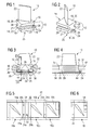
- FIG. 2 show in perspective from different directions a guide vane 10 according to the invention for a turbomachine.
- the vane 10 includes a blade root 12 having two opposite sides 14, 16. Between the two opposite sides 14, 16, a platform 18 is arranged, protruding from the surface 20 of a transversely extending aerodynamically curved blade 22 freestanding.
- a protruding molding 24 is integrally formed in the manner of a tab.
- the molding 24 is arranged centrally near a blade root bottom 25.
- a threaded hole 26 is present, whose threaded axis is oriented perpendicular to the plane of the surface 20 of the platform 18.
- a recess 29 is provided at the other (14) of the two sides 14, 16 .
- the recess 29 of the relevant vane 10 is chosen in its position and size so that when adjacent in a ring vanes 10, the or each fitting 24 - including one disposed therein, in 1 and FIG. 2 Clamping screw not shown - one to the respective vane 10 immediately adjacent vane 10 can be fully absorbed.
- the vane 10 also has two hooks 27 which protrude at a web 23 connecting the two sides 14, 16. Between hook 27 and platform 18 is thereby a respective groove 28 for receiving projections of the circumferential groove is present, in which the guide vane 10 is to be used.
- the web 23 and the hooks 27 have a hammer-like appearance, after which the blade root 12 is also referred to as hammer-shaped.
- the juxtaposed in the circumferential groove vanes 10 are always in such a way that the one side 16 of a first vane 10 of the other side 14 of a second vane 10 is as far as possible opposite each other.
- FIG. 3 shows the longitudinal section through an annular support structure 30, which is part of a stator carrier or a housing of the axially flow-through turbomachine.
- a circumferential groove 34 extending in the circumferential direction is provided.
- the circumferential groove 34 has two mutually opposite side walls 36, 38, on which projections 40, 42 are provided for the positive retention of the guide vane 10.
- guide vane 10 differs from that in the 1 and FIG.
- each have a clamping screw 44 is screwed.
- the clamping screw 44 may be formed for example as a grub screw or as an ordinary screw with a screw head.
- the screw end of the clamping screw 44 is supported on the groove base 35 of the circumferential groove 34 and presses the arranged on the blade root 12 hook 27 to the projections 40, 42 of the circumferential groove 34, whereby the guide vane 10 in the radial direction of the axial flow-through turbomachine firmly biased.
- FIG. 4 shows the cross section through FIG. 3 according to the section line IV-IV, wherein also in FIG. 4 identical features are provided with identical reference numerals.
- the fitting 24 protrudes on the side 16 and is part of the blade root bottom 25.
- recess 29 for receiving a fitting 24 of an adjacent vane 10 of a screwed therein clamping screw 44 can be seen.
- the recess 29 is arranged according to the shaped piece 24 also on the blade root lower side 25.
- FIG. 5 In the following description of the figures and in this figure, the reference numerals of the features associated with a first vane 10a are extended by the suffix a, the reference symbols of the features associated with a second vane 10b by the suffix b and the reference numerals of the features associated with a third vane 10c by the suffix c.
- the first vane 10a is already positioned at its destination and with the help of two madenartiger clamping screws 44a in the circumferential groove 34 firmly clamped.
- two second and third vanes 10b, 10c are already threaded in the circumferential groove 34.
- the second vane 10b immediately adjacent thereto is displaced in the circumferential direction, ie in the direction of the arrow 52, until its platforms 18a, 18b abut one another.
- the fitting 24a of the first vane 10a is disposed in the recess 29b of the second vane 10b, so that from the flow channel view, the platform 18b of the second vane 10b completely covers the molding 24a of the first vane 10a.
- the surface 20b of the platform 18b covers the recess 29b when projected radially.
- the second vane 10b is fastened with the aid of further clamping screws at the corresponding position.
- the third vane 10c can be slid over the molding 24b of the second vane 10b, so that their clamping screws are covered by the platform 18c of the third vane 10c.
- Continued threading and clamping of further guide vanes 10 of the vane ring makes it possible to mount a complete vane ring for an axial-flow turbomachine, in which case all guide vanes 10 are pressed against the projections 40, 42 of the holding groove 34 with a defined pretension.
- the vanes 10 are also for receiving blade root reaction forces according to FIG. 6 further secured.
- a through hole is provided, into which from the rear side of the support structure 30 of a further screw 54 can be screwed with a pin which engages in a corresponding recess on the underside of the blade root 12 of the guide vane 10.
- the invention is not limited to those in 1, 2 and 3 Of course, it is possible, on one side 16 and then two eccentric fittings 24, each with a threaded hole 26 to provide.
- the other side 14 of such a vane 10 then has one or two recesses 29 for receiving the corresponding fittings 24.
- the invention provides a guide vane 10 and a guide vane assembly 50 for an axially permeable turbomachine, in particular compressors, in which each vane 10 is held in a circumferential groove 34 via a fixed clamping.
- a protruding molding 24 is provided with a threaded hole 26 on one side 16 of the blade root 12, in which a on the groove base 35 of the circumferential groove 34 supporting clamping screw 44 can be screwed.
- a particular advantage of the invention is that in the vane ring both the fitting 24 and the clamping screw 44 screwed therein is completely covered by the platform 18 of a neighboring vane 10, so that the intermeshing thread of threaded hole 26 and clamping screw 44 in front of the flow channel the turbo-machine working medium flowing through the surface 20 of the platform 18 is shielded.
- the shield prevents corrosion and the setting of the clamping screw 44, which ensures the disassembly of the guide vanes 10 from the circumferential groove 34 even after a long period of operation safely.
Landscapes
- Engineering & Computer Science (AREA)
- Mechanical Engineering (AREA)
- General Engineering & Computer Science (AREA)
- Structures Of Non-Positive Displacement Pumps (AREA)
Abstract
Description
- Die Erfindung betrifft eine Leitschaufel für eine axial durchströmbare Turbomaschine, umfassend einen zwei einander gegenüberliegende Seiten aufweisenden Schaufelfuß mit einer Plattform und zumindest ein daran angeordnetes Schaufelblatt. Ferner betrifft die Erfindung eine Leitschaufelanordnung mit einer Tragstruktur, an dessen Innenmantelfläche eine Umfangsnut vorgesehen ist, in welcher durch Formschluss gehaltene Leitschaufeln aneinandergereiht sitzen.
- Eine derartige Leitschaufel und Leitschaufelanordnung für einen Verdichter sind beispielsweise aus der
US 2005/0191177 A1 bekannt. In dem von zwei Ringhälften gebildeten Verdichtergehäuse ist für jeden Leitschaufelkranz einer Verdichterstufe eine Umfangsnut vorgesehen. Die Seitenwände der Umfangsnut weisen Hinterscheidungen auf, um darin eingesetzte Leitschaufeln mit entsprechend geformten, hammerförmigen Schaufelfüßen in dieser formschlüssig zu halten. Zwei in der Umfangsnut aneinanderliegende Leitschaufeln weisen in ihren einander gegenüberliegenden Seitenflächen jeweils eine Bohrung auf. In die fluchtenden Bohrungen ist eine Spannhülse zur mechanischen Kopplung der beiden unmittelbar benachbarten Schaufelfüße eingesetzt. Durch die Kopplung sollen Schaufelschwingungen gedämpft und Schaufelfußbewegungen reduziert bzw. verhindert werden, was dadurch Verschleiß an den Schaufelfüßen vermeidet. - Daneben ist aus der
US 6,761,538 B2 ein verspannter Sitz von Laufschaufeln in einer hammerförmigen Umfangsnut bekannt. Zum Aufbringen einer auf die Laufschaufeln in Radialrichtung wirkenden Spannkraft ist im Nutgrund der Umfangsnut eine umlaufende Hohlkehle ausgebildet, in welcher ein auf die Laufschaufel einwirkender Federring eingesetzt ist. Der Federring ist in Form einer gekrümmten Spannhülse ausgebildet, die neben dem üblichen Längsschlitz auch eine Vielzahl von in ihrer Umfangsrichtung verlaufenden Schlitzen aufweist, wodurch dazwischen angeordnete frei endende Federarme entstehen, mittels denen die in der Umfangsnut eingesetzten Laufschaufeln in Radialrichtung verspannt befestigt sind. - Aufgabe der Erfindung ist die Angabe einer alternativen Leitschaufelanordnung und die Bereitstellung einer dafür geeigneten Leitschaufel.
- Die auf die Leitschaufel gerichtete Aufgabe wird mit einer Leitschaufel für eine axial durchströmbare Turbomaschine gelöst, welche einen zwei einander gegenüberliegende Seiten aufweisenden Schaufelfuß mit einer Plattform und zumindest ein daran angeordnetes Schaufelblatt umfasst, wobei der Schaufelfuß an einer der beiden Seiten zumindest ein hervorstehendes Formstück aufweist, in dem zumindest ein Gewindeloch zum radialen Verspannen der Leitschaufel in einer Umfangsnut einer Tragstruktur einer Turbomaschine mittels einer im Gewindeloch eingeschraubten, sich am Nutgrund der Umfangsnut abstützenden Spannschraube vorgesehen ist und bei der der Schaufelfuß an der anderen der beiden Seiten zumindest eine Ausnehmung zur Aufnahme mindestens eines Formstücks einer benachbarten Leitschaufel einschließlich einer darin eingeschraubten Spannschraube aufweist.
- Die auf die Leitschaufelanordnung gerichtete Aufgabe wird mit einer ringförmigen Tragstruktur gelöst, an dessen Innenmantelfläche eine Umfangsnut vorgesehen ist, in welcher durch Formschluss gehaltene Leitschaufeln gemäß vorgenannter Ausgestaltung aneinandergereiht sitzen, wobei jede derartige Leitschaufel mittels einer im Gewindeloch ihres Formstücks eingeschraubten, sich am Nutgrund der Umfangsnut abstützenden Spannschraube in der Umfangsnut verspannt ist und das Formstück einschließlich der Spannschraube vollständig von der Plattform derjenigen Leitschaufel überdeckt ist, welche zur betreffenden Leitschaufel unmittelbar benachbart ist.
- Durch die erfindungsgemäße Leitschaufelanordnung kann eine in Radialrichtung feste Einspannung der Leitschaufel in der Tragstruktur einer axial durchströmbaren Turbomaschine erreicht werden. Da die Spannkraft erst beim Einschrauben und Anziehen der Spannschraube erzeugt wird, kann die Leitschaufel und insbesondere deren Schaufelfuß mit vergleichsweise großen Toleranzen und mit vergleichsweise geringer Passgenauigkeit gegenüber der Kontur der Umfangsnut gefertigt werden. Dies erleichtert einerseits die Positionierung, d.h. Einsetzen und Verschieben der Leitschaufel in der Umfangsnut. Andererseits können dadurch die für eine thermische Dehnung benötigten Spalte in einer ausreichenden Größe vorgehalten werden, was die Leitschaufelanordnung unempfindlicher gegen thermische Einflüsse macht.
- Da die Montagespiele und damit die Fertigungstoleranzen aufgrund des Ausgleichs der größeren Spiele durch die Spannschraube vergrößert werden können, entsteht auch ein Kostenvorteil in der Fertigung der entsprechenden Bauteile.
- Ferner werden durch die Verspannung der Leitschaufel an der Tragstruktur Relativbewegungen der Leitschaufeln blockiert und dadurch möglicher Verschleiß reduziert.
- Zudem weisen die Leitschaufeln aufgrund ihrer spielfreien Befestigung eine definierte radiale Lage auf, wodurch die Radialspalte zwischen den freistehenden Blattspitzen der Leitschaufeln und dem diesen Blattspitzen gegenüberliegenden Rotor enger eingestellt und gefertigt werden können als bisher. Dies reduziert die im Strömungsmedium auftretenden Radialspaltverluste an den Blattspitzen von freistehenden Leitschaufeln während des Betriebs der Turbomaschine, was den Wirkungsgrad der Turbomaschine steigert.
- Damit die zur Verspannung der Leitschaufel benötigte Spannschraube nicht in den Strömungskanal der Turbomaschine hineinragt, ist an einer der beiden einander gegenüberliegenden Seiten des Schaufelfußes ein davon hervorstehendes Formstück angeordnet. Das Formstück ist dabei wesentlich näher an der Unterseite des Schaufelfußes angeordnet als an der Oberfläche der Plattform. In dem Formstück ist ein Gewindeloch vorgesehen, in dem die Spannschraube eingeschraubt werden kann. Da das Formstück seitlich hervorsteht, sind das Gewindeloch und die Spannschraube für die Montagearbeiten besonders gut zugänglich.
- Um eine Strömungskanalbegrenzung der Turbomaschine mit möglichst wenig Bauteilkanten bereitzustellen, ist vorgesehen, dass die Plattform derjenigen Leitschaufel, welche zu einer betreffenden Leitschaufel unmittelbar benachbart angeordnet ist, das Formstück einschließlich der Spannschraube der betreffenden Leitschaufel überdeckt. Hierzu ist an der anderen der zwei einander gegenüberliegenden Seiten des Schaufelfußes zumindest eine Ausnehmung in einer Größe vorgesehen, welche mindestens dem Bauraum des Formstücks einschließlich der darin eingeschraubten Spannschraube entspricht. Durch diese Maßnahme kann lokal eine Strömungskanalbegrenzung allein durch die Oberflächen der Plattformen des Schaufelfußes erreicht werden, ohne dass weitere Bauteile in der Umfangsnut zur Abdeckung des Formstücks einschließlich Spannschraube erforderlich sind. Zudem sind die Spannschrauben mittels der Plattform der benachbarten Leitschaufel vom Strömungsmedium abgeschirmt und somit vor dessen Einflüssen geschützt. Dies verhindert Korrosion und das Festsetzen der Spannschrauben im Gewinde des Lochs.
- Weitere vorteilhafte Ausgestaltungen sind in den Unteransprüchen angegeben.
- Zweckmäßiger Weise ist der Leitschaufelfuß hammerförmig ausgebildet. Gemäß einer weiteren vorteilhaften Ausgestaltung umfasst die Leitschaufel an der einen Seite zwei Formstücke mit jeweils einem Gewindeloch. Hierdurch kann eine Verspannung der Leitschaufel erfolgen, bei der die Spannkraft jeweils nahe an den Seitenwänden der Umfangsnut erzeugt wird und nicht wie bei einer Leitschaufel mit nur einem Formstück, mittig dazwischen. Dies steigert die Sicherheit der Verspannung. Selbstverständlich ist auch denkbar, dass in einem entsprechend großen Formstück zwei Gewindelöcher mit vergleichbarem Abstand vorgesehen sind.
- Selbstverständlich kann die Leitschaufel auch als Leitschaufelsegment ausgebildet sein, welche zwei oder mehr Schaufelblätter aufweist.
- Vorzugsweise handelt es sich bei der Turbomaschine um einen axial durchströmbaren Verdichter, so dass die Leitschaufel als Verdichterleitschaufel oder als Verdichterleitschaufelsegment ausgebildet ist.
- Gemäß einer vorteilhaften Ausgestaltung der Leitschaufelanordnung weist zumindest eine der Leitschaufeln eine Sicherung zur Aufnahme von Schaufelfußreaktionskräften in umlaufender Richtung auf. Üblicher Weise war bisher jede Leitschaufel derartig gesichert. Aufgrund der nunmehr zuverlässigen und mit vergleichsweise großer Kraft verspannten Leitschaufel kann die Anzahl an bisher verwendeten Sicherungen zur Aufnahme an Schaufelfußreaktionskräften reduziert werden, so dass beispielsweise nur noch jede vierte oder jede dritte Leitschaufel zur Aufnahme derartiger Kräfte gesichert werden muss.
- Gemäß einer anderen vorteilhaften Ausgestaltung ist die Tragstruktur als Leitschaufelträger oder als Turbomaschinengehäuse ausgebildet, welches entlang seiner Axialerstreckung hälftig teilbar ist. Dies erleichtert das Einsetzen von Leitschaufeln in der Umfangsnut. Auch wird das Vorsehen eines Leitschaufelschlosses vermieden, welches ansonsten bei einer einstückigen Tragstruktur mit einer dann endlosen Umfangsnut erforderlich wäre.
- Weitere Vorteile, Merkmale und Eigenschaften der Erfindung werden anhand von bevorzugten Ausführungsbeispielen und nachfolgenden Zeichnungen näher erläutert. Es zeigen:
- FIG 1, 2
- eine erfindungsgemäße Leitschaufel gemäß einer ers- ten Ausgestaltung in unterschiedlichen perspektivi- schen Ansichten,
- FIG 3
- den Längsschnitt durch eine Tragstruktur und Leit- schaufel gemäß einer zweiten Ausgestaltung,
- FIG 4
- den Querschnitt durch die Ausgestaltung gemäß
FIG 3 , - FIG 5
- die Abwicklung einer in einer Tragstruktur ange- ordneten Umfangsnut mit darin angeordneten Leit- schaufeln und
- FIG 6
- die Draufsicht auf eine in einer Umfangsnut ange- ordneten Leitschaufel einschließlich einer Siche- rung zur Aufnahme von Schaufelfußreaktionskräften.
-
FIG 1 und FIG 2 zeigen in perspektivischer Darstellung aus unterschiedlichen Blickrichtungen eine erfindungsgemäße Leitschaufel 10 für eine Turbomaschine. Die Leitschaufel 10 umfasst einen Schaufelfuß 12, welcher zwei einander gegenüberliegende Seiten 14, 16 aufweist. Zwischen den beiden gegenüberliegenden Seiten 14, 16 ist eine Plattform 18 angeordnet, von dessen Oberfläche 20 ein sich dazu quer erstreckendes aerodynamisch gekrümmtes Schaufelblatt 22 freistehend hervorragt. - An einer (16) der beiden Seiten 14, 16 ist ein hervorstehendes Formstück 24 nach Art einer Lasche angeformt. Das Formstück 24 ist dabei nahe einer Schaufelfußunterseite 25 mittig angeordnet. Im Formstück 24 ist ein Gewindeloch 26 vorhanden, dessen Gewindeachse senkrecht zur Ebene der Oberfläche 20 der Plattform 18 ausgerichtet ist.
- An der anderen (14) der beiden Seiten 14, 16 ist eine Ausnehmung 29 vorgesehen. Die Ausnehmung 29 der betreffenden Leitschaufel 10 ist dabei in ihrer Lage und ihrer Größe so gewählt, dass bei in einem Kranz aneinanderliegenden Leitschaufeln 10 das oder jedes Formstück 24 - einschließlich einer darin angeordneten, in
FIG 1 und FIG 2 nicht dargestellten Spannschraube - einer zur betreffenden Leitschaufel 10 unmittelbar benachbarten Leitschaufel 10 vollständig aufgenommen werden kann. - Die Leitschaufel 10 weist zudem zwei Haken 27 auf, die an einem die beiden Seiten 14, 16 verbindenden Steg 23 hervorstehen. Zwischen Haken 27 und Plattform 18 ist dadurch jeweils eine Nut 28 zur Aufnahme von Vorsprüngen der Umfangsnut vorhanden, in welche die Leitschaufel 10 eingesetzt werden soll. Der Steg 23 und die Haken 27 haben eine hammerförmige Anmutung, wonach der Schaufelfuß 12 auch als hammerförmig bezeichnet wird.
- Die in der Umfangsnut aneinandergereihten Leitschaufeln 10 liegen stets derartig aneinander, dass die eine Seite 16 einer ersten Leitschaufel 10 der anderen Seite 14 einer zweiten Leitschaufel 10 möglichst spaltlos einander gegenüber steht.
-
FIG 3 zeigt den Längsschnitt durch eine ringförmige Tragstruktur 30, die Teil eines Leitschaufelträgers oder eines Gehäuses der axial durchströmbaren Turbomaschine ist. An dessen innerer Mantelfläche 32 ist eine in Umfangsrichtung verlaufende Umfangsnut 34 vorgesehen. Die Umfangsnut 34 weist zwei einander gegenüberliegende Seitenwände 36, 38 auf, an denen Vorsprünge 40, 42 zur formschlüssigen Halterung der Leitschaufel 10 vorgesehen sind. Die inFIG 3 dargestellte Leitschaufel 10 unterscheidet sich von der in derFIG 1 und FIG 2 dargestellten Leitschaufel 10 darin, dass das an der einen Seite 16 angeordnete Formstück 24 sich nahezu über die gesamte Breite des Schaufelfußes 12 bzw. der Umfangsnut 34 erstreckt und dass darin insgesamt zwei Gewindelöcher 26 vorgesehen sind, die nicht mittig zwischen den Seitenwänden 36, 38 der Umfangsnut 34 angeordnet sind, sondern seitenwandnah. - In den Gewindelöchern 26 ist jeweils eine Spannschraube 44 eingeschraubt. Die Spannschraube 44 kann beispielsweise als Madenschraube oder auch als gewöhnliche Schraube mit einem Schraubenkopf ausgebildet sein. Das Schraubenende der Spannschraube 44 stützt sich am Nutgrund 35 der Umfangsnut 34 ab und drückt dabei die am Schaufelfuß 12 angeordneten Haken 27 an die Vorsprünge 40, 42 der Umfangsnut 34, wodurch die Leitschaufel 10 in Radialrichtung der axial durchströmbaren Turbomaschine fest vorgespannt anliegt.
-
FIG 4 zeigt den Querschnitt durchFIG 3 gemäß der Schnittlinie IV-IV, wobei auch inFIG 4 identische Merkmale mit identischen Bezugszeichen versehen sind. AusFIG 4 geht klar hervor, dass das Formstück 24 an der Seite 16 hervorsteht und dabei ein Teil der Schaufelfußunterseite 25 ist. Gleichfalls ist inFIG 4 die an der gegenüberliegenden Seite 14 vorhandene Ausnehmung 29 zur Aufnahme eines Formstücks 24 einer benachbarten Leitschaufel 10 einer einschließlich darin eingeschraubten Spannschraube 44 zu erkennen. Die Ausnehmung 29 ist entsprechend dem Formstück 24 auch an der Schaufelfußunterseite 25 angeordnet. -
FIG 5 zeigt einen Teil der Abwicklung einer Leitschaufelanordnung 50 mit Tragstruktur 30 und Umfangsnut 34. In der nachfolgenden Figurenbeschreibung und in dieser Figur sind die Bezugszeichen der zu einer ersten Leitschaufel 10a zugehörigen Merkmale um den Suffix a erweitert, die Bezugszeichen der zu einer zweiten Leitschaufel 10b zugehörigen Merkmale um den Suffix b und die Bezugszeichen der zu einer dritten Leitschaufel 10c zugehörigen Merkmale um den Suffix c. Die erste Leitschaufel 10a ist bereits an ihrem Bestimmungsort positioniert und mit Hilfe zweier madenartiger Spannschrauben 44a in der Umfangsnut 34 fest verspannt. Zur weiteren Bestückung der Leitschaufelanordnung 50 mit Leitschaufeln sind bereits zwei zweite und dritte Leitschaufeln 10b, 10c in der Umfangsnut 34 eingefädelt. Nach dem Verspannen der ersten Leitschaufel 10a wird die dazu unmittelbar benachbarte, zweite Leitschaufel 10b in Umfangsrichtung, d. h. in Richtung des Pfeils 52 verschoben, bis deren Plattformen 18a, 18b aneinander anliegen. Dabei ist dann das Formstück 24a der ersten Leitschaufel 10a in der Ausnehmung 29b der zweiten Leitschaufel 10b angeordnet, so dass aus Strömungskanalansicht die Plattform 18b der zweiten Leitschaufel 10b das Formstück 24a der ersten Leitschaufel 10a vollständig überdeckt. Genau gesagt überdeckt die Oberfläche 20b der Plattform 18b bei radialer Projektion die Ausnehmung 29b. Anschließend wird die zweite Leitschaufel 10b mit Hilfe weiterer Spannschrauben an der entsprechenden Position befestigt. Sonach kann die dritte Leitschaufel 10c über das Formstück 24b der zweiten Leitschaufel 10b geschoben werden, so dass auch deren Spannschrauben von der Plattform 18c der dritten Leitschaufel 10c verdeckt sind. Durch fortgeführtes Einfädeln und Verspannen von weiteren Leitschaufeln 10 des Leitschaufelkranzes kann ein vollständiger Leitschaufelkranz für eine axial durchströmte Turbomaschine montiert werden, wobei dann alle Leitschaufeln 10 mit einer definierten Vorspannung an den Vorsprüngen 40, 42 der Haltenut 34 angepresst werden. - Die Leitschaufeln 10 sind zudem zur Aufnahme von Schaufelfußreaktionskräften gemäß
FIG 6 weiter gesichert. Im Nutgrund 35 der Haltenut 34 ist hierzu ein Durchgangsloch vorhanden, in das von rückwärtiger Seite der Tragstruktur 30 aus eine weitere Schraube 54 mit einem Zapfen einschraubbar ist, der in eine dazu korrespondierende Ausnehmung an der Unterseite des Schaufelfußes 12 der Leitschaufel 10 eingreift. - Die Erfindung beschränkt sich nicht auf die in
FIG 1, 2 und 3 gezeigten Ausgestaltungen von Leitschaufeln 10. Selbstverständlich ist es möglich, an der einen Seite 16 auch zwei dann außermittige Formstücke 24 mit jeweils einem Gewindeloch 26 vorzusehen. Die andere Seite 14 einer derartigen Leitschaufel 10 weist dann eine oder zwei Ausnehmungen 29 zur Aufnahme der entsprechenden Formstücke 24 auf. - Insgesamt wird mit der Erfindung eine Leitschaufel 10 und eine Leitschaufelanordnung 50 für eine axial durchströmbare Turbomaschine, insbesondere Verdichter angegeben, bei der jede Leitschaufel 10 über eine feste Einspannung in einer Umfangsnut 34 gehaltert ist. Zur festen Einspannung ist an einer Seite 16 des Schaufelfußes 12 ein hervorstehendes Formstück 24 mit einem Gewindeloch 26 vorgesehen, in welches eine sich am Nutgrund 35 der Umfangsnut 34 abstützende Spannschraube 44 einschraubbar ist. Ein besonderer Vorteil der Erfindung liegt darin, dass im Leitschaufelkranz sowohl das Formstück 24 als auch die darin eingeschraubte Spannschraube 44 von der Plattform 18 einer dazu benachbarten Leitschaufel 10 vollständig überdeckt ist, so dass die ineinandergreifenden Gewinde von Gewindeloch 26 und Spannschraube 44 vor dem im Strömungskanal der Turbomaschine strömenden Arbeitsmedium durch die Oberfläche 20 der Plattform 18 abgeschirmt ist. Die Abschirmung verhindert Korrosion und das Festsetzen der Spannschraube 44, was die Demontage der Leitschaufeln 10 aus der Umfangsnut 34 selbst nach längerer Betriebsdauer sicher gewährleistet.
Claims (9)
- Leitschaufel (10) für eine axial durchströmbare Turbomaschine,
umfassend einen zwei einander gegenüberliegende Seiten (14, 16) aufweisenden Schaufelfuß (12) mit einer Plattform (18) und zumindest ein daran angeordnetes Schaufelblatt (22), dadurch gekennzeichnet, dass
der Schaufelfuß (12) an einer der beiden Seiten (16) zumindest ein hervorstehendes Formstück (24) aufweist, in dem zumindest ein Gewindeloch (26) zum radialen Verspannen der Leitschaufel (10) in einer Umfangsnut (34) einer Tragstruktur (30) einer Turbomaschine mittels einer darin eingeschraubten, sich am Nutgrund (35) der Umfangsnut (34) abstützenden Spannschraube (44) vorgesehen ist und bei der der Schaufelfuß (12) an der anderen der beiden Seiten (14) zumindest eine Ausnehmung (29) zur Aufnahme mindestens eines Formstücks (24) einer benachbarten Leitschaufel (10) einschließlich einer darin eingeschraubten Spannschraube (44) aufweist. - Leitschaufel (10) nach Anspruch 1,
dessen Schaufelfuß (12) hammerförmig ausgebildet ist. - Leitschaufel (10) nach Anspruch 1 oder 2,
mit zwei jeweils ein Gewindeloch (26) aufweisenden Formstücken (24) oder mit zwei Gewindelöchern (26) in dem einen Formstück (24). - Leitschaufel (10) nach einem der Ansprüche 1 bis 3,
bei der das Formstück (24) zumindest vergleichsweise nah an der Schaufelfußunterseite (25) angeformt ist. - Leitschaufel (10) nach einem der Ansprüche 1 bis 4,
welche als Leitschaufelsegment zwei oder mehr Schaufelblätter (22) aufweist. - Leitschaufel (10) nach einem der Ansprüche 1 bis 5,
ausgebildet als Verdichterleitschaufel eines axial durchströmbaren Verdichters. - Leitschaufelanordnung (50) für eine Turbomaschine, vorzugsweise Verdichter,
mit einer ringförmigen Tragstruktur (30), an dessen Innenmantelfläche (32) eine Umfangsnut (34) vorgesehen ist, in welcher durch Formschluss gehaltene Leitschaufeln (10) nach einem der Ansprüche 1 bis 5 aneinandergereiht sitzen, wobei jede derartige Leitschaufel (10) mittels einer im Gewindeloch (26) ihres Formstücks (24) eingeschraubten, sich am Nutgrund (35) der Umfangsnut (34) abstützenden Spannschraube (44) in der Umfangsnut (34) verspannt ist und das Formstück (24) einschließlich der Spannschraube (44) vollständig von der Plattform (18) derjenigen Leitschaufel (10) überdeckt ist, welche zur betreffenden Leitschaufel (10) unmittelbar benachbart ist. - Leitschaufelanordnung (50) nach Anspruch 7,
bei der zumindest eine der Leitschaufeln (10) eine Sicherung zur Aufnahme von Schaufelfußreaktionskräften in umlaufender Richtung aufweist. - Leitschaufelanordnung (50) nach einem der Ansprüche 7 oder 8,
bei der die Tragstruktur (30) hälftig teilbar ist.
Priority Applications (5)
| Application Number | Priority Date | Filing Date | Title |
|---|---|---|---|
| EP09011070A EP2295724B1 (de) | 2009-08-28 | 2009-08-28 | Leitschaufel für eine axial durchströmbare Turbomaschine und zugehörige Leitschaufelanordnung |
| AT09011070T ATE547591T1 (de) | 2009-08-28 | 2009-08-28 | Leitschaufel für eine axial durchströmbare turbomaschine und zugehörige leitschaufelanordnung |
| US12/868,946 US8622708B2 (en) | 2009-08-28 | 2010-08-26 | Stator blade for a turbomachine which is exposable to axial throughflow, and also stator blade arrangement for it |
| JP2010190834A JP5073027B2 (ja) | 2009-08-28 | 2010-08-27 | 軸方向に貫流可能なターボマシンのための静翼及び静翼構造 |
| CN201010268815XA CN102003219B (zh) | 2009-08-28 | 2010-08-27 | 可轴向通流的涡轮机的导向叶片及其导向叶片装置 |
Applications Claiming Priority (1)
| Application Number | Priority Date | Filing Date | Title |
|---|---|---|---|
| EP09011070A EP2295724B1 (de) | 2009-08-28 | 2009-08-28 | Leitschaufel für eine axial durchströmbare Turbomaschine und zugehörige Leitschaufelanordnung |
Publications (2)
| Publication Number | Publication Date |
|---|---|
| EP2295724A1 true EP2295724A1 (de) | 2011-03-16 |
| EP2295724B1 EP2295724B1 (de) | 2012-02-29 |
Family
ID=41395104
Family Applications (1)
| Application Number | Title | Priority Date | Filing Date |
|---|---|---|---|
| EP09011070A Not-in-force EP2295724B1 (de) | 2009-08-28 | 2009-08-28 | Leitschaufel für eine axial durchströmbare Turbomaschine und zugehörige Leitschaufelanordnung |
Country Status (5)
| Country | Link |
|---|---|
| US (1) | US8622708B2 (de) |
| EP (1) | EP2295724B1 (de) |
| JP (1) | JP5073027B2 (de) |
| CN (1) | CN102003219B (de) |
| AT (1) | ATE547591T1 (de) |
Cited By (2)
| Publication number | Priority date | Publication date | Assignee | Title |
|---|---|---|---|---|
| WO2013102591A1 (de) * | 2012-01-03 | 2013-07-11 | Siemens Aktiengesellschaft | Befestigung einer schlossschaufel an einer rotoreinheit |
| WO2014062270A2 (en) | 2012-08-27 | 2014-04-24 | United Technologies Corporation | Shiplap cantilevered stator |
Families Citing this family (17)
| Publication number | Priority date | Publication date | Assignee | Title |
|---|---|---|---|---|
| CN103717909A (zh) * | 2011-08-04 | 2014-04-09 | 诺克有限公司 | 轴流式鼓风机 |
| US8888459B2 (en) * | 2011-08-23 | 2014-11-18 | General Electric Company | Coupled blade platforms and methods of sealing |
| JP5555727B2 (ja) * | 2012-01-23 | 2014-07-23 | 川崎重工業株式会社 | 軸流圧縮機翼の製造方法 |
| JP6012222B2 (ja) * | 2012-03-30 | 2016-10-25 | 三菱重工業株式会社 | 静翼セグメント、これを備える軸流流体機械及びその静翼連結方法 |
| WO2014130981A2 (en) | 2013-02-25 | 2014-08-28 | Greenheck Fan Corporation | Mixed flow fan assembly |
| US10184488B2 (en) | 2013-02-25 | 2019-01-22 | Greenheck Fan Corporation | Fan housing having flush mounted stator blades |
| US9505092B2 (en) | 2013-02-25 | 2016-11-29 | Greenheck Fan Corporation | Methods for fan assemblies and fan wheel assemblies |
| US10125783B2 (en) | 2013-02-25 | 2018-11-13 | Greenheck Fan Corporation | Fan assembly and fan wheel assemblies |
| BE1022361B1 (fr) * | 2014-11-06 | 2016-03-17 | Techspace Aero Sa | Stator mixte de compresseur de turbomachine axiale. |
| WO2017083406A1 (en) * | 2015-11-10 | 2017-05-18 | Matternet, Inc. | Methods and systems for transportation using unmanned aerial vehicles |
| JP6641654B2 (ja) * | 2016-01-08 | 2020-02-05 | 三菱日立パワーシステムズ株式会社 | 動翼の取外方法、この方法を実行するための取外装置、この取外装置を備えるロータセット |
| GB2551164B (en) * | 2016-06-08 | 2019-12-25 | Rolls Royce Plc | Metallic stator vane |
| CN106988794B (zh) * | 2017-06-02 | 2018-12-14 | 中国航发南方工业有限公司 | 静子组合件夹紧方法及静子组合件 |
| US10934863B2 (en) * | 2018-11-13 | 2021-03-02 | Rolls-Royce Corporation | Turbine wheel assembly with circumferential blade attachment |
| EP4041633A4 (de) * | 2019-10-09 | 2023-10-18 | Kitty Hawk Corporation | Hybridleistungssysteme für verschiedene flugbetriebsarten |
| DE102020200447A1 (de) * | 2020-01-15 | 2021-07-15 | Ziehl-Abegg Se | Gehäuse für einen Ventilator und Ventilator mit einem entsprechenden Gehäuse |
| CN112943685B (zh) * | 2021-03-10 | 2022-09-13 | 哈电发电设备国家工程研究中心有限公司 | 一种拉杆式叶根连接结构 |
Citations (5)
| Publication number | Priority date | Publication date | Assignee | Title |
|---|---|---|---|---|
| EP0899426A2 (de) * | 1997-08-23 | 1999-03-03 | Mtu Motoren- Und Turbinen-Union MàNchen Gmbh | Leitschaufel für eine Gasturbine |
| US20030185673A1 (en) * | 2002-01-21 | 2003-10-02 | Honda Giken Kogyo Kabushiki Kaisha | Flow-rectifying member and its unit and method for producing flow-rectifying member |
| US6761538B2 (en) | 2002-10-31 | 2004-07-13 | General Electric Company | Continual radial loading device for steam turbine reaction type buckets and related method |
| US20050191177A1 (en) | 2002-02-22 | 2005-09-01 | Anderson Rodger O. | Compressor stator vane |
| EP2093383A1 (de) * | 2008-02-19 | 2009-08-26 | United Technologies Corporation | Leitschaufel und Leitschaufelanordnung |
Family Cites Families (9)
| Publication number | Priority date | Publication date | Assignee | Title |
|---|---|---|---|---|
| US1061640A (en) * | 1910-10-10 | 1913-05-13 | Colonial Trust Co | Blading. |
| US3252687A (en) * | 1965-02-01 | 1966-05-24 | Gen Motors Corp | Rotor blade locking |
| CH581783A5 (de) * | 1975-01-30 | 1976-11-15 | Bbc Sulzer Turbomaschinen | |
| US4645425A (en) * | 1984-12-19 | 1987-02-24 | United Technologies Corporation | Turbine or compressor blade mounting |
| US5713721A (en) * | 1996-05-09 | 1998-02-03 | General Electric Co. | Retention system for the blades of a rotary machine |
| ITMI20012783A1 (it) * | 2001-12-21 | 2003-06-21 | Nuovo Pignone Spa | Sistema di connessione e bloccaggio di pale rotoriche di un compressore assiale |
| EP1619354B1 (de) * | 2004-07-22 | 2008-04-09 | Siemens Aktiengesellschaft | Sicherungsvorrichtung für eine an einer drehbaren Rotorscheibe angeordneten Laufschaufel einer Strömungsmaschine, Strömungsmaschine und Verfahren zur Montage und Demontage einer Laufschaufel an einer Rotorscheibe einer Strömungsmaschine |
| JP4760090B2 (ja) * | 2005-03-30 | 2011-08-31 | ブラザー工業株式会社 | 搬送装置及び画像形成装置 |
| EP1788198A2 (de) * | 2005-11-21 | 2007-05-23 | The General Electric Company | Befestigungssystem für Turbinenschaufeln und Verfahren |
-
2009
- 2009-08-28 AT AT09011070T patent/ATE547591T1/de active
- 2009-08-28 EP EP09011070A patent/EP2295724B1/de not_active Not-in-force
-
2010
- 2010-08-26 US US12/868,946 patent/US8622708B2/en not_active Expired - Fee Related
- 2010-08-27 CN CN201010268815XA patent/CN102003219B/zh not_active Expired - Fee Related
- 2010-08-27 JP JP2010190834A patent/JP5073027B2/ja not_active Expired - Fee Related
Patent Citations (5)
| Publication number | Priority date | Publication date | Assignee | Title |
|---|---|---|---|---|
| EP0899426A2 (de) * | 1997-08-23 | 1999-03-03 | Mtu Motoren- Und Turbinen-Union MàNchen Gmbh | Leitschaufel für eine Gasturbine |
| US20030185673A1 (en) * | 2002-01-21 | 2003-10-02 | Honda Giken Kogyo Kabushiki Kaisha | Flow-rectifying member and its unit and method for producing flow-rectifying member |
| US20050191177A1 (en) | 2002-02-22 | 2005-09-01 | Anderson Rodger O. | Compressor stator vane |
| US6761538B2 (en) | 2002-10-31 | 2004-07-13 | General Electric Company | Continual radial loading device for steam turbine reaction type buckets and related method |
| EP2093383A1 (de) * | 2008-02-19 | 2009-08-26 | United Technologies Corporation | Leitschaufel und Leitschaufelanordnung |
Cited By (4)
| Publication number | Priority date | Publication date | Assignee | Title |
|---|---|---|---|---|
| WO2013102591A1 (de) * | 2012-01-03 | 2013-07-11 | Siemens Aktiengesellschaft | Befestigung einer schlossschaufel an einer rotoreinheit |
| WO2014062270A2 (en) | 2012-08-27 | 2014-04-24 | United Technologies Corporation | Shiplap cantilevered stator |
| EP2888450A4 (de) * | 2012-08-27 | 2016-11-02 | United Technologies Corp | Freitragender stufenfalzstator |
| EP3339608A3 (de) * | 2012-08-27 | 2018-09-05 | United Technologies Corporation | Freitragender stufenfalzstator |
Also Published As
| Publication number | Publication date |
|---|---|
| JP2011047406A (ja) | 2011-03-10 |
| US8622708B2 (en) | 2014-01-07 |
| CN102003219B (zh) | 2013-12-18 |
| JP5073027B2 (ja) | 2012-11-14 |
| US20110052397A1 (en) | 2011-03-03 |
| EP2295724B1 (de) | 2012-02-29 |
| CN102003219A (zh) | 2011-04-06 |
| ATE547591T1 (de) | 2012-03-15 |
Similar Documents
| Publication | Publication Date | Title |
|---|---|---|
| EP2295724B1 (de) | Leitschaufel für eine axial durchströmbare Turbomaschine und zugehörige Leitschaufelanordnung | |
| EP1944471B1 (de) | Axialer Rotorabschnitt für einen Rotor einer Turbine | |
| EP2399004B1 (de) | Rotorabschnitt für einen rotor einer turbomaschine, laufschaufel für eine turbomaschine und blockierelement | |
| EP2569514B1 (de) | Befestigungsanordnung für schaufeln von axial durchströmten turbomaschinen sowie verfahren zum herstellen einer solchen | |
| DE102009003714B4 (de) | Turbinenstatorschaufelhaltesystem und -verfahren | |
| EP2268902B1 (de) | Strebe für ein turbinenzwischengehäuse und turbinenzwischengehäuse | |
| EP2459425B1 (de) | Baugruppe bestehend aus einem ausgleichsbehälter und einem hauptzylinder für eine hydraulische kraftfahrzeugbremsanlage | |
| EP1922471A1 (de) | Anordnung zur axialsicherung von laufschaufeln in einem rotor sowie verwendung | |
| EP1803899A1 (de) | Schlussbaugruppe für einen Schaufelkranz einer Strömungsmaschine | |
| EP1148209B1 (de) | Zwischenstufendichtungsanordnung | |
| DE19547653A1 (de) | Leitvorrichtung für eine Turbine mit einem Leitschaufelträger und Verfahren zur Herstellung dieser Leitvorrichtung | |
| EP2823152A1 (de) | Turbinenlaufschaufel und axialer rotorabschnitt für eine gasturbine | |
| DE102004057025B4 (de) | Verfahren zum Installieren von ortsfesten Schaufeln einer Turbine und Turbinenstruktur mit einem radialen Spannstift | |
| EP1840338B1 (de) | Anordnung zur Axialsicherung an Laufschaufeln in einem Rotor sowie Gasturbine mit einer solchen Anordnung | |
| DE3341871C2 (de) | ||
| EP3176386B1 (de) | Innenringsystem, zugehöriger innenring, zwichengehäuse und strömungsmaschine | |
| DE112019004011T5 (de) | Montagesystem für ein Kastenprofil | |
| EP3181918B1 (de) | Befestigungsanordnung | |
| EP0965729B1 (de) | Schloss für Laufschaufeln eines Turbinenläufers | |
| EP2149677A1 (de) | Befestigungsanordnung zur Befestigung von einer Laufschaufel an einem Rotor einer Turbomaschine | |
| DE102008013118A1 (de) | Anordnung zum Befestigen von Turbinenschaufeln | |
| EP1350924B1 (de) | Statorschaufelsegmentbefestigung für eine Gasturbine | |
| EP1860280A1 (de) | Verriegelungsvorrichtung einer Turbinenschaufel mit einem Sperrelement | |
| EP2246575A1 (de) | Laufschaufelanordnung für einen Axialverdichter | |
| DE102013212501A1 (de) | Leitschaufelsegment mit stirnseitiger Ausnehmung |
Legal Events
| Date | Code | Title | Description |
|---|---|---|---|
| PUAI | Public reference made under article 153(3) epc to a published international application that has entered the european phase |
Free format text: ORIGINAL CODE: 0009012 |
|
| AK | Designated contracting states |
Kind code of ref document: A1 Designated state(s): AT BE BG CH CY CZ DE DK EE ES FI FR GB GR HR HU IE IS IT LI LT LU LV MC MK MT NL NO PL PT RO SE SI SK SM TR |
|
| AX | Request for extension of the european patent |
Extension state: AL BA RS |
|
| GRAP | Despatch of communication of intention to grant a patent |
Free format text: ORIGINAL CODE: EPIDOSNIGR1 |
|
| 17P | Request for examination filed |
Effective date: 20110808 |
|
| RIC1 | Information provided on ipc code assigned before grant |
Ipc: F04D 29/54 20060101ALI20110822BHEP Ipc: F01D 9/04 20060101ALI20110822BHEP Ipc: F01D 5/30 20060101AFI20110822BHEP |
|
| GRAS | Grant fee paid |
Free format text: ORIGINAL CODE: EPIDOSNIGR3 |
|
| GRAA | (expected) grant |
Free format text: ORIGINAL CODE: 0009210 |
|
| AK | Designated contracting states |
Kind code of ref document: B1 Designated state(s): AT BE BG CH CY CZ DE DK EE ES FI FR GB GR HR HU IE IS IT LI LT LU LV MC MK MT NL NO PL PT RO SE SI SK SM TR |
|
| REG | Reference to a national code |
Ref country code: GB Ref legal event code: FG4D Free format text: NOT ENGLISH Ref country code: CH Ref legal event code: EP |
|
| REG | Reference to a national code |
Ref country code: AT Ref legal event code: REF Ref document number: 547591 Country of ref document: AT Kind code of ref document: T Effective date: 20120315 |
|
| REG | Reference to a national code |
Ref country code: IE Ref legal event code: FG4D Free format text: LANGUAGE OF EP DOCUMENT: GERMAN |
|
| REG | Reference to a national code |
Ref country code: CH Ref legal event code: NV Representative=s name: SIEMENS SCHWEIZ AG |
|
| REG | Reference to a national code |
Ref country code: DE Ref legal event code: R096 Ref document number: 502009002880 Country of ref document: DE Effective date: 20120426 |
|
| REG | Reference to a national code |
Ref country code: NL Ref legal event code: T3 |
|
| LTIE | Lt: invalidation of european patent or patent extension |
Effective date: 20120229 |
|
| PG25 | Lapsed in a contracting state [announced via postgrant information from national office to epo] |
Ref country code: LT Free format text: LAPSE BECAUSE OF FAILURE TO SUBMIT A TRANSLATION OF THE DESCRIPTION OR TO PAY THE FEE WITHIN THE PRESCRIBED TIME-LIMIT Effective date: 20120229 Ref country code: NO Free format text: LAPSE BECAUSE OF FAILURE TO SUBMIT A TRANSLATION OF THE DESCRIPTION OR TO PAY THE FEE WITHIN THE PRESCRIBED TIME-LIMIT Effective date: 20120529 Ref country code: HR Free format text: LAPSE BECAUSE OF FAILURE TO SUBMIT A TRANSLATION OF THE DESCRIPTION OR TO PAY THE FEE WITHIN THE PRESCRIBED TIME-LIMIT Effective date: 20120229 Ref country code: IS Free format text: LAPSE BECAUSE OF FAILURE TO SUBMIT A TRANSLATION OF THE DESCRIPTION OR TO PAY THE FEE WITHIN THE PRESCRIBED TIME-LIMIT Effective date: 20120629 |
|
| PG25 | Lapsed in a contracting state [announced via postgrant information from national office to epo] |
Ref country code: LV Free format text: LAPSE BECAUSE OF FAILURE TO SUBMIT A TRANSLATION OF THE DESCRIPTION OR TO PAY THE FEE WITHIN THE PRESCRIBED TIME-LIMIT Effective date: 20120229 Ref country code: FI Free format text: LAPSE BECAUSE OF FAILURE TO SUBMIT A TRANSLATION OF THE DESCRIPTION OR TO PAY THE FEE WITHIN THE PRESCRIBED TIME-LIMIT Effective date: 20120229 Ref country code: GR Free format text: LAPSE BECAUSE OF FAILURE TO SUBMIT A TRANSLATION OF THE DESCRIPTION OR TO PAY THE FEE WITHIN THE PRESCRIBED TIME-LIMIT Effective date: 20120530 Ref country code: PT Free format text: LAPSE BECAUSE OF FAILURE TO SUBMIT A TRANSLATION OF THE DESCRIPTION OR TO PAY THE FEE WITHIN THE PRESCRIBED TIME-LIMIT Effective date: 20120629 |
|
| REG | Reference to a national code |
Ref country code: IE Ref legal event code: FD4D |
|
| PG25 | Lapsed in a contracting state [announced via postgrant information from national office to epo] |
Ref country code: CY Free format text: LAPSE BECAUSE OF FAILURE TO SUBMIT A TRANSLATION OF THE DESCRIPTION OR TO PAY THE FEE WITHIN THE PRESCRIBED TIME-LIMIT Effective date: 20120229 |
|
| PG25 | Lapsed in a contracting state [announced via postgrant information from national office to epo] |
Ref country code: SI Free format text: LAPSE BECAUSE OF FAILURE TO SUBMIT A TRANSLATION OF THE DESCRIPTION OR TO PAY THE FEE WITHIN THE PRESCRIBED TIME-LIMIT Effective date: 20120229 Ref country code: RO Free format text: LAPSE BECAUSE OF FAILURE TO SUBMIT A TRANSLATION OF THE DESCRIPTION OR TO PAY THE FEE WITHIN THE PRESCRIBED TIME-LIMIT Effective date: 20120229 Ref country code: SE Free format text: LAPSE BECAUSE OF FAILURE TO SUBMIT A TRANSLATION OF THE DESCRIPTION OR TO PAY THE FEE WITHIN THE PRESCRIBED TIME-LIMIT Effective date: 20120229 Ref country code: EE Free format text: LAPSE BECAUSE OF FAILURE TO SUBMIT A TRANSLATION OF THE DESCRIPTION OR TO PAY THE FEE WITHIN THE PRESCRIBED TIME-LIMIT Effective date: 20120229 Ref country code: CZ Free format text: LAPSE BECAUSE OF FAILURE TO SUBMIT A TRANSLATION OF THE DESCRIPTION OR TO PAY THE FEE WITHIN THE PRESCRIBED TIME-LIMIT Effective date: 20120229 Ref country code: IE Free format text: LAPSE BECAUSE OF FAILURE TO SUBMIT A TRANSLATION OF THE DESCRIPTION OR TO PAY THE FEE WITHIN THE PRESCRIBED TIME-LIMIT Effective date: 20120229 Ref country code: DK Free format text: LAPSE BECAUSE OF FAILURE TO SUBMIT A TRANSLATION OF THE DESCRIPTION OR TO PAY THE FEE WITHIN THE PRESCRIBED TIME-LIMIT Effective date: 20120229 Ref country code: PL Free format text: LAPSE BECAUSE OF FAILURE TO SUBMIT A TRANSLATION OF THE DESCRIPTION OR TO PAY THE FEE WITHIN THE PRESCRIBED TIME-LIMIT Effective date: 20120229 |
|
| PG25 | Lapsed in a contracting state [announced via postgrant information from national office to epo] |
Ref country code: SK Free format text: LAPSE BECAUSE OF FAILURE TO SUBMIT A TRANSLATION OF THE DESCRIPTION OR TO PAY THE FEE WITHIN THE PRESCRIBED TIME-LIMIT Effective date: 20120229 |
|
| PLBE | No opposition filed within time limit |
Free format text: ORIGINAL CODE: 0009261 |
|
| STAA | Information on the status of an ep patent application or granted ep patent |
Free format text: STATUS: NO OPPOSITION FILED WITHIN TIME LIMIT |
|
| 26N | No opposition filed |
Effective date: 20121130 |
|
| BERE | Be: lapsed |
Owner name: SIEMENS A.G. Effective date: 20120831 |
|
| REG | Reference to a national code |
Ref country code: DE Ref legal event code: R097 Ref document number: 502009002880 Country of ref document: DE Effective date: 20121130 |
|
| PG25 | Lapsed in a contracting state [announced via postgrant information from national office to epo] |
Ref country code: MC Free format text: LAPSE BECAUSE OF NON-PAYMENT OF DUE FEES Effective date: 20120831 |
|
| PG25 | Lapsed in a contracting state [announced via postgrant information from national office to epo] |
Ref country code: ES Free format text: LAPSE BECAUSE OF FAILURE TO SUBMIT A TRANSLATION OF THE DESCRIPTION OR TO PAY THE FEE WITHIN THE PRESCRIBED TIME-LIMIT Effective date: 20120609 |
|
| REG | Reference to a national code |
Ref country code: FR Ref legal event code: ST Effective date: 20130430 |
|
| PG25 | Lapsed in a contracting state [announced via postgrant information from national office to epo] |
Ref country code: BE Free format text: LAPSE BECAUSE OF NON-PAYMENT OF DUE FEES Effective date: 20120831 |
|
| PG25 | Lapsed in a contracting state [announced via postgrant information from national office to epo] |
Ref country code: BG Free format text: LAPSE BECAUSE OF FAILURE TO SUBMIT A TRANSLATION OF THE DESCRIPTION OR TO PAY THE FEE WITHIN THE PRESCRIBED TIME-LIMIT Effective date: 20120529 |
|
| PG25 | Lapsed in a contracting state [announced via postgrant information from national office to epo] |
Ref country code: FR Free format text: LAPSE BECAUSE OF NON-PAYMENT OF DUE FEES Effective date: 20120831 |
|
| PG25 | Lapsed in a contracting state [announced via postgrant information from national office to epo] |
Ref country code: MT Free format text: LAPSE BECAUSE OF FAILURE TO SUBMIT A TRANSLATION OF THE DESCRIPTION OR TO PAY THE FEE WITHIN THE PRESCRIBED TIME-LIMIT Effective date: 20120229 |
|
| PG25 | Lapsed in a contracting state [announced via postgrant information from national office to epo] |
Ref country code: TR Free format text: LAPSE BECAUSE OF FAILURE TO SUBMIT A TRANSLATION OF THE DESCRIPTION OR TO PAY THE FEE WITHIN THE PRESCRIBED TIME-LIMIT Effective date: 20120229 |
|
| PG25 | Lapsed in a contracting state [announced via postgrant information from national office to epo] |
Ref country code: SM Free format text: LAPSE BECAUSE OF FAILURE TO SUBMIT A TRANSLATION OF THE DESCRIPTION OR TO PAY THE FEE WITHIN THE PRESCRIBED TIME-LIMIT Effective date: 20120229 Ref country code: LU Free format text: LAPSE BECAUSE OF NON-PAYMENT OF DUE FEES Effective date: 20120828 |
|
| PG25 | Lapsed in a contracting state [announced via postgrant information from national office to epo] |
Ref country code: HU Free format text: LAPSE BECAUSE OF FAILURE TO SUBMIT A TRANSLATION OF THE DESCRIPTION OR TO PAY THE FEE WITHIN THE PRESCRIBED TIME-LIMIT Effective date: 20090828 |
|
| PG25 | Lapsed in a contracting state [announced via postgrant information from national office to epo] |
Ref country code: MK Free format text: LAPSE BECAUSE OF FAILURE TO SUBMIT A TRANSLATION OF THE DESCRIPTION OR TO PAY THE FEE WITHIN THE PRESCRIBED TIME-LIMIT Effective date: 20120229 |
|
| PGFP | Annual fee paid to national office [announced via postgrant information from national office to epo] |
Ref country code: NL Payment date: 20150804 Year of fee payment: 7 |
|
| REG | Reference to a national code |
Ref country code: AT Ref legal event code: MM01 Ref document number: 547591 Country of ref document: AT Kind code of ref document: T Effective date: 20140828 |
|
| PGFP | Annual fee paid to national office [announced via postgrant information from national office to epo] |
Ref country code: GB Payment date: 20150812 Year of fee payment: 7 |
|
| PG25 | Lapsed in a contracting state [announced via postgrant information from national office to epo] |
Ref country code: AT Free format text: LAPSE BECAUSE OF NON-PAYMENT OF DUE FEES Effective date: 20140828 |
|
| PGFP | Annual fee paid to national office [announced via postgrant information from national office to epo] |
Ref country code: IT Payment date: 20150825 Year of fee payment: 7 |
|
| PGFP | Annual fee paid to national office [announced via postgrant information from national office to epo] |
Ref country code: DE Payment date: 20151016 Year of fee payment: 7 Ref country code: CH Payment date: 20151102 Year of fee payment: 7 |
|
| REG | Reference to a national code |
Ref country code: DE Ref legal event code: R119 Ref document number: 502009002880 Country of ref document: DE |
|
| REG | Reference to a national code |
Ref country code: CH Ref legal event code: PL |
|
| REG | Reference to a national code |
Ref country code: NL Ref legal event code: MM Effective date: 20160901 |
|
| GBPC | Gb: european patent ceased through non-payment of renewal fee |
Effective date: 20160828 |
|
| PG25 | Lapsed in a contracting state [announced via postgrant information from national office to epo] |
Ref country code: LI Free format text: LAPSE BECAUSE OF NON-PAYMENT OF DUE FEES Effective date: 20160831 Ref country code: CH Free format text: LAPSE BECAUSE OF NON-PAYMENT OF DUE FEES Effective date: 20160831 |
|
| PG25 | Lapsed in a contracting state [announced via postgrant information from national office to epo] |
Ref country code: NL Free format text: LAPSE BECAUSE OF NON-PAYMENT OF DUE FEES Effective date: 20160901 |
|
| PG25 | Lapsed in a contracting state [announced via postgrant information from national office to epo] |
Ref country code: DE Free format text: LAPSE BECAUSE OF NON-PAYMENT OF DUE FEES Effective date: 20170301 Ref country code: GB Free format text: LAPSE BECAUSE OF NON-PAYMENT OF DUE FEES Effective date: 20160828 |
|
| PG25 | Lapsed in a contracting state [announced via postgrant information from national office to epo] |
Ref country code: IT Free format text: LAPSE BECAUSE OF NON-PAYMENT OF DUE FEES Effective date: 20160828 |