EP2294429B1 - Behandlungs- und/oder analysegerät mit einer klammer zum greifen eines biologischen probenhalters - Google Patents
Behandlungs- und/oder analysegerät mit einer klammer zum greifen eines biologischen probenhalters Download PDFInfo
- Publication number
- EP2294429B1 EP2294429B1 EP09772705.1A EP09772705A EP2294429B1 EP 2294429 B1 EP2294429 B1 EP 2294429B1 EP 09772705 A EP09772705 A EP 09772705A EP 2294429 B1 EP2294429 B1 EP 2294429B1
- Authority
- EP
- European Patent Office
- Prior art keywords
- biological sample
- gripping
- sample holder
- arm
- along
- Prior art date
- Legal status (The legal status is an assumption and is not a legal conclusion. Google has not performed a legal analysis and makes no representation as to the accuracy of the status listed.)
- Active
Links
Images


Classifications
-
- B—PERFORMING OPERATIONS; TRANSPORTING
- B01—PHYSICAL OR CHEMICAL PROCESSES OR APPARATUS IN GENERAL
- B01L—CHEMICAL OR PHYSICAL LABORATORY APPARATUS FOR GENERAL USE
- B01L9/00—Supporting devices; Holding devices
- B01L9/50—Clamping means, tongs
-
- G—PHYSICS
- G01—MEASURING; TESTING
- G01N—INVESTIGATING OR ANALYSING MATERIALS BY DETERMINING THEIR CHEMICAL OR PHYSICAL PROPERTIES
- G01N35/00—Automatic analysis not limited to methods or materials provided for in any single one of groups G01N1/00 - G01N33/00; Handling materials therefor
- G01N35/02—Automatic analysis not limited to methods or materials provided for in any single one of groups G01N1/00 - G01N33/00; Handling materials therefor using a plurality of sample containers moved by a conveyor system past one or more treatment or analysis stations
- G01N35/028—Automatic analysis not limited to methods or materials provided for in any single one of groups G01N1/00 - G01N33/00; Handling materials therefor using a plurality of sample containers moved by a conveyor system past one or more treatment or analysis stations having reaction cells in the form of microtitration plates
-
- B—PERFORMING OPERATIONS; TRANSPORTING
- B01—PHYSICAL OR CHEMICAL PROCESSES OR APPARATUS IN GENERAL
- B01L—CHEMICAL OR PHYSICAL LABORATORY APPARATUS FOR GENERAL USE
- B01L9/00—Supporting devices; Holding devices
- B01L9/52—Supports specially adapted for flat sample carriers, e.g. for plates, slides, chips
- B01L9/523—Supports specially adapted for flat sample carriers, e.g. for plates, slides, chips for multisample carriers, e.g. used for microtitration plates
-
- G—PHYSICS
- G01—MEASURING; TESTING
- G01N—INVESTIGATING OR ANALYSING MATERIALS BY DETERMINING THEIR CHEMICAL OR PHYSICAL PROPERTIES
- G01N35/00—Automatic analysis not limited to methods or materials provided for in any single one of groups G01N1/00 - G01N33/00; Handling materials therefor
- G01N35/0099—Automatic analysis not limited to methods or materials provided for in any single one of groups G01N1/00 - G01N33/00; Handling materials therefor comprising robots or similar manipulators
-
- G—PHYSICS
- G01—MEASURING; TESTING
- G01N—INVESTIGATING OR ANALYSING MATERIALS BY DETERMINING THEIR CHEMICAL OR PHYSICAL PROPERTIES
- G01N35/00—Automatic analysis not limited to methods or materials provided for in any single one of groups G01N1/00 - G01N33/00; Handling materials therefor
- G01N35/02—Automatic analysis not limited to methods or materials provided for in any single one of groups G01N1/00 - G01N33/00; Handling materials therefor using a plurality of sample containers moved by a conveyor system past one or more treatment or analysis stations
- G01N35/04—Details of the conveyor system
-
- B—PERFORMING OPERATIONS; TRANSPORTING
- B01—PHYSICAL OR CHEMICAL PROCESSES OR APPARATUS IN GENERAL
- B01L—CHEMICAL OR PHYSICAL LABORATORY APPARATUS FOR GENERAL USE
- B01L2200/00—Solutions for specific problems relating to chemical or physical laboratory apparatus
- B01L2200/14—Process control and prevention of errors
- B01L2200/141—Preventing contamination, tampering
-
- B—PERFORMING OPERATIONS; TRANSPORTING
- B25—HAND TOOLS; PORTABLE POWER-DRIVEN TOOLS; MANIPULATORS
- B25J—MANIPULATORS; CHAMBERS PROVIDED WITH MANIPULATION DEVICES
- B25J15/00—Gripping heads and other end effectors
- B25J15/0033—Gripping heads and other end effectors with gripping surfaces having special shapes
- B25J15/0042—V-shaped gripping surfaces
-
- G—PHYSICS
- G01—MEASURING; TESTING
- G01N—INVESTIGATING OR ANALYSING MATERIALS BY DETERMINING THEIR CHEMICAL OR PHYSICAL PROPERTIES
- G01N35/00—Automatic analysis not limited to methods or materials provided for in any single one of groups G01N1/00 - G01N33/00; Handling materials therefor
- G01N35/02—Automatic analysis not limited to methods or materials provided for in any single one of groups G01N1/00 - G01N33/00; Handling materials therefor using a plurality of sample containers moved by a conveyor system past one or more treatment or analysis stations
- G01N35/04—Details of the conveyor system
- G01N2035/0401—Sample carriers, cuvettes or reaction vessels
- G01N2035/0418—Plate elements with several rows of samples
- G01N2035/042—Plate elements with several rows of samples moved independently, e.g. by fork manipulator
-
- G—PHYSICS
- G01—MEASURING; TESTING
- G01N—INVESTIGATING OR ANALYSING MATERIALS BY DETERMINING THEIR CHEMICAL OR PHYSICAL PROPERTIES
- G01N35/00—Automatic analysis not limited to methods or materials provided for in any single one of groups G01N1/00 - G01N33/00; Handling materials therefor
- G01N35/02—Automatic analysis not limited to methods or materials provided for in any single one of groups G01N1/00 - G01N33/00; Handling materials therefor using a plurality of sample containers moved by a conveyor system past one or more treatment or analysis stations
- G01N35/026—Automatic analysis not limited to methods or materials provided for in any single one of groups G01N1/00 - G01N33/00; Handling materials therefor using a plurality of sample containers moved by a conveyor system past one or more treatment or analysis stations having blocks or racks of reaction cells or cuvettes
-
- Y—GENERAL TAGGING OF NEW TECHNOLOGICAL DEVELOPMENTS; GENERAL TAGGING OF CROSS-SECTIONAL TECHNOLOGIES SPANNING OVER SEVERAL SECTIONS OF THE IPC; TECHNICAL SUBJECTS COVERED BY FORMER USPC CROSS-REFERENCE ART COLLECTIONS [XRACs] AND DIGESTS
- Y10—TECHNICAL SUBJECTS COVERED BY FORMER USPC
- Y10S—TECHNICAL SUBJECTS COVERED BY FORMER USPC CROSS-REFERENCE ART COLLECTIONS [XRACs] AND DIGESTS
- Y10S901/00—Robots
- Y10S901/30—End effector
- Y10S901/31—Gripping jaw
- Y10S901/36—Actuating means
Definitions
- the present invention relates to a gripper adapted to capture a biological sample support, an assembly of a biological sample support and a gripper adapted to grip it, and an automated processing and / or analysis of samples. organic.
- the GRIFOLS company markets a biological sample processing and analysis automaton, comprising a gripper of the type adapted to grip a first support of biological samples comprising a wall provided with two opposite lateral edges, and receptacles for biological samples carried. by the wall, the wall extending along a direction intended, in normal use of the first biological sample holder, to be vertical with the receptacles opening upwards, the clamp comprising first and second movable arms with respect to each other along a gripping direction between a first gripping position of the first biological sample holder, and a first releasing position of the biological sample holder.
- this known clamp has been designed to grip a "gel" type card which further comprises an upper flange, fixed to the upper edge of the main plate and perpendicular thereto.
- the upper edge extends over the entire length of the upper edge.
- the first and second arms extend downward from a base of the clip.
- the first and second arms are intended to grip the gel card in the width of the upper rim, from below the upper rim.
- the capture is made in the middle of the length of the upper edge, with the base of the clamp in front of this upper edge.
- fingers also start from the base, downwards, to surround the upper edge of the gel card.
- a disadvantage of the foregoing known clamp is that there is a significant risk of contamination of biological samples by the forceps.
- An object of the invention is to provide a clamp adapted to grip a gel card, with low risk of contamination of biological samples.
- the invention relates to a clamp of the aforementioned type, characterized in that: the first arm comprises a first groove; the second arm comprises a second groove; when the first and second arms are in the first release position, the first and second grooves are spaced from each other according to the direction of entry; and when the first and second arms are in the first gripping position, the first and second grooves are brought closer to each other along the gripping direction and extend facing each other, in order to be able to receive the lateral edges of the support of biological samples, in order to grip the support of biological samples by gripping the lateral edges in the direction of capture.
- the first groove has a first transverse profile of which at least part is “V” along a first groove direction; the second groove has a second transverse profile of which at least a portion is “V” along a second groove direction; and when the first and second arms are in the first gripping position, the "V" portion of the first transverse profile and the "V” portion of the second transverse profile are open to each other.
- the first and second groove directions are parallel to each other within 10 ° and perpendicular to the direction of capture to 10 °.
- the first arm comprises a first projecting portion
- the second arm comprises a second projecting portion
- the projecting parts allow the arms to be moved away from the gel card, which further reduces the risk of contamination by contact or proximity to the upper rim, particularly in the case where the arms are connected to a base of the clamp intended to to extend above the top edge of the gel card.
- the first groove comprises two open ends
- the second groove comprises two open ends
- the clamp is adapted to capture, in place of the first biological sample holder, a second biological sample holder comprising first and second parallel parallel side walls, a upper wall connecting the first and second side walls, and biological sample receptacles, carried by the upper wall, the first and second side walls being intended, in normal use of the second biological sample holder, to extend vertically , with the receptacles opening upwards, and, secondly: the first and second arms are movable relative to each other in the direction of capture between a second gripping position of the second support of biological samples , and a second release position of the second biological sample support, the first and second input positions being identical, and the first and second release positions may be identical; the first arm comprises a first contact face with the first side wall of the second biological sample holder; the second arm comprises a second contact face with the second side wall of the second biological sample holder; when the first and second arms are in the second releasing position, the first and second contact faces are spaced apart from
- the clip is capable of gripping sample holders having smooth sidewalls.
- the first protruding part comprises the first contact face, and the first contact face is separated in two by the first groove; and the second projecting portion comprises the second contact face, and the second contact face is separated in two by the second groove.
- the invention also relates to an assembly of a first biological sample holder and a clamp according to the invention.
- the invention also relates to an automated processing and / or analysis of biological samples, characterized in that it comprises: a clamp according to the invention; a first station for processing or analyzing biological samples received in the receptacles of a first support for biological samples; a first storage location of at least a first support of biological samples; and an articulated arm, to which the clip is attached, configured to move the clip from the first storage location to capture a first biological sample holder, to the processing or analysis station for releasing the first support therefrom. biological samples, so that the latter is treated or analyzed.
- treatment means any action on the biological samples, including pipetting into the receptacles of a biological sample holder.
- the automaton comprises: a second processing station or analysis of biological samples received in the receptacles of a second support of biological samples; and a second storage location of at least a second biological sample holder, and the articulated arm, to which the clip is attached, is configured to move the clip from the second storage location to capture a second medium biological samples, up to the treatment or analysis station to release the second support biological samples, so that it is treated or analyzed.
- the invention relates to the analysis of biological samples, whether they are transported in "gel” type cards, or in "microplates".
- biological sample support in addition to all the gel cards and all the microplates, any other form of biological sample container having the claimed structural characteristics allows it to be grasped. by the clip according to the invention.
- a gel card 10 which is marketed for example by DIAMED, Cressier, Switzerland, forms a biological sample support comprising a rectangular main wall 12, provided with two opposite lateral edges 14, 16.
- the gel card 10 comprises, in addition to an upper flange 20 attached to the main wall 12 and extending between the two side edges 14, 16, perpendicular to the main wall 12.
- the gel board 10 further comprises receptacles 18 of biological samples, tube-shaped 18, carried by the wall 12 and opening through the upper rim 20.
- a gel card generally comprises six receiving tubes 18.
- the main wall 12 and the tubes 18 extend along the vertical direction, with the upper flange 20 upwards, so that the tubes 18 open upwards, as shown. on the figure 1 .
- the gel card 10 further comprises a bar code 22 inscribed on a face 24 of the main wall 12, below the tubes 18.
- the side edges 14, 16 generally have a height of 100 mm or less, for example 52 mm, and are separated by a length d1 of 140 mm or less, for example 70 mm.
- the main wall 12 has a thickness of 2 mm or less, for example 1.2 mm, and a weight of 10 grams or less, for example 6 grams.
- the upper flange 20 has a width of 20 mm or less, for example 9 mm.
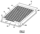
- a microplate 30 which is commercially available for example from NUNC, Denmark, forms a biological sample carrier comprising a rectangular main wall 32 comprising an upper face 34.
- the microplate 30 further comprises sidewalls 38 extending perpendicularly. to the main wall 32 from the edges of this wall 32, opposite the upper face 34.
- the side walls 38 comprise first and second large side walls 38A, 38B opposite and parallel to each other, and opposite transverse walls 38C , 38D.
- the microplate 30 further comprises receptacles 40 of biological samples, in the form of half-cups, carried by the main wall 32.
- the receptacles 40 open through the upper face 34.
- the receptacles 40 are arranged in a matrix, for example 12 by 8 containers.
- the main wall 32 is intended to be horizontal, with the upper face 34 upwards, so that the receptacles 40 open upwards.
- the microplate 30 further comprises a bar code 42 inscribed on the upper face 34 of the wall 32.
- the microplate 30 is generally made of polystyrene and weighs less than 60 grams, typically 35 grams.
- the wall 32 has dimensions less than 200 mm by 150 mm, for example 128 mm by 85 mm.
- the side walls 38 generally have a height of 30 mm or less, for example 15 mm.
- the first and second large side walls 38A, 38B are thus separated by a distance d2 of less than 150 mm, for example 85 mm.
- a controller for the processing and analysis of biological samples, whether received in gel cards or in microplates, has been designated by the general reference 50.
- the positioning and orientation of the elements of the controller 50 will be made with reference to an orthogonal reference axis X, Y, Z axes, attached to the controller 50.
- the Y axis In normal use position of the controller 50, the Y axis is intended to be vertical. The Y axis thus defines a vertical direction Y.
- the X and Z axes are intended to extend horizontally.
- the X axis defines a longitudinal direction X
- the Z axis defines a transverse direction Z.
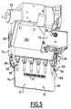
- the controller 50 comprises a chamber 52 in the form of a cabinet with a length in the longitudinal direction X and a width in the transverse direction Z.
- the enclosure 52 comprises an open longitudinal rear face 53 and a pivoting flap (not shown) for closing the open face 53.
- the controller 50 comprises, in the chamber 52, a slide 56 for storing gel cards and microplates.
- the drawer 56 is mounted in translation along the transverse axis Z so that the drawer 56 can be opened towards the front of the controller 50.
- the drawer 56 comprises a plurality of locations 57, each slot 57 being designed to receive either a microplate or a basket of gel cards, in which the gel cards are aligned, with their main walls substantially parallel to each other.
- the controller 50 comprises, in the chamber 52, transverse passages 59 for loading test tubes or bottles of biological samples, a longitudinal ramp 61 for receiving gel cards or microplates, and robots 62 for pipetting the samples. gel cards or microplates received on the ramp 61.
- the ramp 61 comprises transverse slots, each designed to receive the main wall of a gel card, or one of the transverse walls 38C, 38D of a microplate.
- the controller 50 comprises, in the enclosure 52, an incubator 62 having the same shape as the ramp 61 and further comprising a heating device (not shown).
- the automaton comprises, in the chamber 52, centrifuges 63 of gel cards and a device 64 for analyzing biological samples contained in a gel card.
- the controller 50 is further adapted to accommodate a device (not shown) for analyzing biological samples contained in a microplate.
- the automaton 50 also comprises a clamp 70 intended to capture each time one of the supports arranged in the automaton 50, whether it is a gel card or a microplate.
- the automaton 50 comprises an articulated transport arm 72 of the clamp 70.
- the transport arm 72 is hinged along the three dimensions of the space, in order to be able to move the clamp 70 between the storage drawer 56 and the treatment stations 61, 62, 63 and 64.
- the articulated arm 72 always keeps the same orientation to the clamp 70.
- the clip 70 grasping a gel card 10.
- the clamp 70 includes an upper base 74 for attachment to the articulated arm 72, and first and second arms 76, 78 extending downwardly from the base 74.
- the first arm 76 is provided with a first high end 80 connected to the base 74 by a first pivot connection 82 in the longitudinal direction X
- the second arm 78 is provided with a second high end 84 connected to the base 74 by a second pivot connection 86 in the longitudinal direction X.
- the first and second arms 76, 78 are thus configured to pivot in the longitudinal direction. X with respect to the base 74, in the vertical plane YZ.
- the first arm 76 is further provided with a first lower end 88 for gripping the gel card 10
- the second arm 78 is further provided with a second lower end 90 for gripping the gel card 10.
- the first and second lower ends 88, 90 are intended for gripping the gel card 10 by gripping the latter.
- the base 74 comprises a rotary electric motor 92 for driving, by a "small mechanical" type motion transmission device, first and second arms 76, 78 of the clamp 70, in order to pass the first and second arms 76. , 78 between a first position, represented on the figures 4 and 5 , gripping the gel card 70, and a release position of the gel card 10.
- first and second arms 76, 78 are in the release position, the first and second gripping ends 88, 90 are spaced apart. the other in the transverse direction Z.
- the first and second gripping ends 88, 90 are brought closer to each other along the transverse direction Z.
- the first gripping end 88 includes a first projecting portion 94 facing the second arm 78
- the second gripping end 90 includes a second projecting portion 96 facing the first arm 76.
- the first arm 76 comprises a first groove 98 for receiving the vertical wall 12 of the gel card 10, formed in the first projecting portion 94.
- the second arm 78 comprises a second groove 100 for receiving the vertical wall 12 of the gel card 10, formed in the second projecting portion 96.
- the first and second grooves 98, 100 extend in the vertical plane YZ, that is to say that the vertical plane YZ passes in each of the first and second grooves 98, 100.
- the first and second grooves 98, 100 each have their two ends open.
- the first groove 98 is provided with a bottom 102, an opening 104 opposite the bottom 102 and side walls 106 connecting the bottom 102 to the opening 104.
- the first groove 98 has a transverse profile, it is in the horizontal plane XZ when the arms 76, 78 are in the first gripping position, in "V" along a first groove direction, perpendicular to the plane of the figure 7 .
- the side walls 106 thus meet at the bottom 102, and move away from the other away from the bottom 102 towards the opening 104.
- the first groove direction is vertical.
- the second groove 100 is identical to the first groove 98 and thus comprises a bottom 108, an opening 110, side walls 112 and a second groove direction, all arranged in the same manner as for the first groove 98.
- the spacing along the transverse axis Z between the first and second grooves 98, 100 is greater in the release position than in the gel card gripping position. More precisely, the side walls 106 and 112 are separated in the transverse direction Z, in the release position, by a distance greater than the distance d1, and, in the first input position, by a distance equal to the distance d1 .
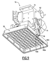
- the clip 70 is shown gripping a microplate 30.
- the first projecting portion 94 comprises a first advanced face 114 of contact with the first side wall 38A of the microplate 30, and the second projecting portion 96 comprises a second advanced face 116 of contact with the second side wall 38B of the microplate 30.
- the motor 92 is further configured to move the first and second arms 76, 78 between the releasing position and a second gripping position of the microplate 30. As the distance d2 is greater than the distance d1 , the second input position is located between the release position and the first input position.
- the first and second forward faces 114, 116 are brought closer to the releasing position of each other in the transverse direction Z and are facing each other, so as to be able to contact, respectively, the first side wall 38A and the second side wall 38B of the microplate 30, in order to grip the microplate 30 by gripping the first and second side walls 38A, 38B in the transverse direction Z.
- first and second contact surfaces 114, 116 are separated in the transverse direction Z, in release position, by a distance greater than d2, and, in the gripping position of the plate by a distance substantially equal at d2.
- first and second contact faces 114, 116 are each inclined relative to their respective arms 76, 78 so that, in the gripping position, they are substantially parallel to each other.
- the first contact face 114 is separated in two by the first groove 98, and the second contact face 116 is separated in two by the second groove 100.
- the first arm 76 further comprises a first blade 118 cantilevered with respect to the first contact face 114, the first cantilever blade 118 comprising two cantilevered ends 118A, 118B, each disposed on a respective side of the first groove 98.
- the second arm 78 further comprises a second cantilever blade 120 relative to the second contact face 116, the second blade being cantilever assembly comprising two cantilevered ends 120A, 120B, each disposed on a respective side of the second groove 100.
- the first cantilever blade 118 and in particular each end 118A, 118B, is intended to be folded in contact with the first side wall 38A, in order to reduce sliding between the first contact face 114 and the first wall lateral 38A.
- the second cantilever blade 120 and in particular each end 120A, 120B, is intended to be folded in contact with the second side wall 38B, in order to reduce sliding between the second contact face 116 and the second side wall 38B.
- each end 118A, 118B, 120A, 120B has an upward curved shape towards the base 74 of the clamp 70, so that each end 118A, 118B, 120A, 120B is folded upwardly in contact with the microplate 30.
- the weight of the microplate 30 tends to unfold the ends downwards, which pushes these ends even more against the walls 38A, 38B, and thus increases the friction with these walls, thereby reducing the risk of slipping.
- the first and second cantilever blades thus reduce the risk that the microplate 30 escapes from the clamp 70.
- the figure 10 illustrates the contact between the first arm 76 and the first lateral face 38A of the microplate 30.
- the clamp 70 further comprises a device 122 for detecting the presence of a gel card or a microplate, grasped by the clamp 70.
- a device 122 for detecting the presence of a gel card or a microplate, grasped by the clamp 70 This is for example an optical reflection sensor.
- the clamp 70 further comprises a bar code reader 124 having a reading beam 126 for enabling the reading of both the bar code of the gel card 10 and the reading of the bar code of the microplate 30.
- An operator opens the drawer 56, places in the slots 57 of the baskets containing empty gel cards, and / or empty microplates, then closes the drawer 56.
- the operator loads test tubes and / or vials containing biological samples, eg patients, into the transverse lanes 59.
- the arm 72 moves the clip 70 to read the bar codes of the stored empty gel cards.
- the gripper 70 captures an empty gel card, selected for example by its bar code. Thanks to the advantageous shape of the grooves 98, 100, the gel card is entered even if its placement in the basket is approximate.
- the arm 72 moves the clamp 70 as far as the ramp 61, where the clamp 70 releases the gel card.
- One of the robots 60 then transfers biological samples into the receptacles 18 of the gel card placed on the ramp 61.
- the gel card is moved by the clamp 70 successively into the incubator 62, then into one of the centrifuges 63, then into the analysis device 64.
- the arm 72 moves the clamp 70 to the drawer 56, where the clamp 70 grasps an empty microplate.
- the arm 72 moves the clamp 70 to the ramp 61, where the clamp 70 releases the microplate.
- One of the robots 60 then transfers biological samples into the receptacles of the microplate placed on the ramp 61.
- the arm 72 and the gripper 70 then transfer the microplate containing the biological samples either to the slide 56, where the operator can retrieve it to carry out additional treatments outside the controller 50 or at the analysis station. biological samples of microplates, when this is provided in the controller 50.
Landscapes
- Chemical & Material Sciences (AREA)
- Health & Medical Sciences (AREA)
- General Physics & Mathematics (AREA)
- Immunology (AREA)
- Life Sciences & Earth Sciences (AREA)
- Analytical Chemistry (AREA)
- Biochemistry (AREA)
- General Health & Medical Sciences (AREA)
- Pathology (AREA)
- Physics & Mathematics (AREA)
- Chemical Kinetics & Catalysis (AREA)
- Clinical Laboratory Science (AREA)
- Engineering & Computer Science (AREA)
- Robotics (AREA)
- Automatic Analysis And Handling Materials Therefor (AREA)
- Apparatus Associated With Microorganisms And Enzymes (AREA)
- Sampling And Sample Adjustment (AREA)
- Investigating Or Analysing Biological Materials (AREA)
Claims (14)
- Automat zum Bearbeiten und / oder Analysieren von biologischen Proben des Typs aufweisend:- eine erste Speicherstelle (57), die zumindest einen ersten Träger für biologische Proben (10) speichert, welcher eine Wand (12) mit zwei gegenüberliegenden Seitenrändern (14, 16) und Behälter (18) für biologische Proben aufweist, welche mittels der Wand (12) getragen sind, wobei die Wand (12) sich mit den vertikalen Seitenrändern (14, 16) vertikal erstreckt und die Behälter (18) nach oben ausmünden, wobei der erste Träger für biologische Proben (10) eine Gel-Karte ist, und- einen Gelenkarm (72), an dem eine Klemme (70) zum Greifen des ersten Trägers für biologische Proben (10) befestigt ist, wobei die Klemme (70) einen ersten Arm und einen zweiten Arm (76, 78) aufweist, welche relativ zueinander entlang einer Greifrichtung (Z) zwischen einer ersten Position zum Greifen des ersten Trägers für biologische Proben (10) und einer ersten Position zum Freilassen des Trägers für biologische Proben (10) bewegbar sind,wobei der Automat dadurch gekennzeichnet ist, dass:- der erste Arm (76) der Klemme (70) eine erste Nut (98) aufweist,- der zweite Arm (78) der Klemme (70) eine zweite Nut (100) aufweist,- wenn der erste Arm und der zweite Arm (76, 78) in erster Position zum Freilassen sind, die erste Nut und die zweite Nut (98, 100) entlang der Greifrichtung (Z) im Abstand voneinander sind, und,- wenn der erste Arm und der zweite Arm (76, 78) in erster Position zum Greifen sind, die erste Nut und die zweite Nut (98, 100) entlang der Greifrichtung (Z) einander angenähert sind und sich gegenüberliegend erstrecken, um die Seitenränder (14, 16) des ersten Trägers für biologische Proben (10) zu empfangen, um ihn mittels Einfassens der Seitenränder (14, 16) entlang der Greifrichtung (Z) zu greifen.
- Automat nach Anspruch 1, ferner dadurch gekennzeichnet, dass:- der erste Arm (76) einen ersten Vorsprungsabschnitt (94) aufweist und der zweite Arm (78) einen zweiten Vorsprungsabschnitt (96) aufweist, wobei- wenn der erste Arm und der zweite Arm (76, 78) in erster Position zum Greifen sind, der erste Vorsprungsabschnitt und der zweite Vorsprungsabschnitt (94, 96) in Bezug auf ihren jeweiligen Arm entlang der Greifrichtung (Z) vorstehen, und wobei- die erste Nut (98) in dem ersten Vorsprungsabschnitt (94) und die zweite Nut (100) in dem zweiten Vorsprungsabschnitt (96) angeordnet ist.
- Automat nach Anspruch 1 oder 2, ferner dadurch gekennzeichnet, dass er aufweist:- eine zweite Speicherstelle (57), welche einen zweiten Träger für biologische Proben (30) speichert, welcher eine erste Seitenwand und eine zweite Seitenwand (38A, 38B), welche parallel gegenüberliegend angeordnet sind, eine obere Wand (32), welche die erste Seitenwand und die zweite Seitenwand (38A 38B) verbindet, und Behälter für biologische Proben (40) aufweist, welche mittels der oberen Wand (32) getragen sind, wobei die erste Seitenwand und die zweite Seitenwand (38A, 38B) sich vertikal erstrecken, wobei die Behältern (40) nach oben hin ausmünden,und dadurch, dass:- die Klemme (70) eingerichtet ist, um anstelle des ersten Trägers für biologische Proben (10) den zweiten Träger für biologische Proben (30) zu greifen,- der erste Arm und der zweite Arm (76, 78) relativ zueinander entlang der Greifrichtung (Z) zwischen einer zweiten Position zum Greifen des zweiten Trägers für biologische Proben (30) und einer zweiten Position zum Freilassen des zweiten Trägers für biologische Proben (30) bewegbar sind, wobei die erste Position zum Greifen und die zweite Position zum Greifen identisch sein können und die erste Position zum Freilassen und die zweite Position zum Freilassen identisch sein können,- der erste Arm (76) eine erste Kontaktfläche (114) mit der ersten Seitenwand (38A) des zweiten Trägers für biologische Proben (30) aufweist,- der zweite Arm (78) eine zweite Kontaktfläche (116) mit der zweiten Seitenwand (38B) des zweiten Trägers für biologische Proben (30) aufweist,- wenn der erste Arm und der zweite Arm (76, 78) in zweiter Position zum Freilassen sind, die erste Kontaktfläche und die zweite Kontaktfläche (114, 116) entlang der Greifposition (Z) im Abstand voneinander sind, und,- wenn der erste Arm und der zweite Arm (76, 78) in zweiter Position zum Greifen sind, die erste Kontaktfläche und die zweite Kontaktfläche (114, 116) entlang der Greifrichtung (Z) einander angenähert sind und gegenüberliegend sind, um in Kontakt jeweils mit der ersten Seitenwand (38A) und der zweiten Seitenwand (38B) des zweiten Trägers für biologische Proben (30) zu treten, um den Träger für biologische Proben (30) mittels Einfassens der ersten Seitenwand und der zweiten Seitenwand (38A, 38B) entlang der Greifrichtung (Z) zu greifen.
- Automat nach Anspruch 3, dadurch gekennzeichnet, dass der zweite Träger für biologische Proben eine Mikrotiterplatte ist.
- Automat nach Anspruch 3 oder 4, ferner dadurch gekennzeichnet, dass:- der erste Arm (76) erste Mittel (118) zum Reduzieren des Schlupfs mit der ersten Seitenwand (38A) aufweist, und- der zweite Arm (78) zweite Mittel (120) zum Reduzieren des Schlupfs mit der zweiten Seitenwand (38B) aufweist.
- Automat nach Anspruch 5, ferner dadurch gekennzeichnet, dass:- die ersten Mittel zum Reduzieren des Schlupfs ein erstes Blatt (118) aufweisen, welches in Bezug auf die erste Kontaktfläche (38A) frei auskragend ist, wobei das erste frei auskragende Blatt (118) dazu bestimmt ist, in Kontakt mit der ersten Seitenwand (38A) gefaltet zu werden, und- die zweiten Mittel zum Reduzieren des Schlupfs ein zweites Blatt (120) aufweisen, welches in Bezug auf die zweite Kontaktfläche (38B) frei auskragend ist, wobei das zweite frei auskragende Blatt (120) dazu bestimmt ist, in Kontakt mit der zweiten Seitenwand (38B) gefaltet zu werden.
- Automat nach Anspruch 2 und Anspruch 5 oder 6, ferner dadurch gekennzeichnet, dass:- der erste Vorsprungsabschnitt (94) die erste Kontaktfläche (114) aufweist und die erste Kontaktfläche (114) mittels der ersten Nut (98) in zwei getrennt ist, und- der zweite Vorsprungsabschnitt (96) die zweite Kontaktfläche (116) aufweist und die zweite Kontaktfläche (116) mittels der zweiten Nut (100) in zwei getrennt ist.
- Verfahren zum Greifen eines ersten Trägers für biologische Proben (10) mittels einer Klemme (70) entlang einer Greifrichtung (Z),
wobei der erste Träger für biologische Proben (10) eine Gel-Karte ist, aufweisend eine Wand (12) mit zwei gegenüberliegenden Seitenrändern (14, 16) und Behälter (18) für biologische Proben, welche mittels der Wand (12) getragen sind und welche durch einen Sims (20) hindurch ausmünden, der die beiden Seitenränder (20) verbindet, wobei die Wand (12) sich mit dem oberen Sims (20) vertikal nach oben erstreckt,
wobei das Verfahren gekennzeichnet ist durch die Verlagerung des ersten Arms und des zweiten Arms (76, 78) der Klemme (70), die jeweilig eine erste Nut und eine zweite Nut (98, 100) aufweisen, von einer ersten Position zum Freilassen aus, in der die erste Nut und die zweite Nut (98, 100) entlang der Greifrichtung (Z) im Abstand voneinander sind, bis zu einer ersten Position zum Greifen, in der die erste Nut und die zweite Nut (98, 100) entlang der Greifrichtung (Z) einander angenähert sind, sich gegenüberliegend erstrecken und die Seitenränder (14, 16) des ersten Trägers für biologische Proben (10) empfangen, um ihn mittels Erfassens der Seitenränder (14, 16) entlang der Greifrichtung (Z) zu greifen. - Verfahren nach Anspruch 8, ferner dadurch gekennzeichnet, dass:- der erste Arm (76) einen ersten Vorsprungsabschnitt (94) aufweist und der zweite Arm (78) einen zweiten Vorsprungsabschnitt (96) aufweist,- wenn der erste Arm und der zweite Arm (76, 78) in erster Position zum Greifen sind, der erste Vorsprungsabschnitt und der zweite Vorsprungsabschnitt (94, 96) in Bezug auf ihren jeweiligen Arm entlang der Greifrichtung (Z) vorstehen, und- die erste Nut (98) in dem ersten Vorsprungsabschnitt (94) angeordnet ist und die zweite Nut (100) in dem zweiten Vorsprungsabschnitt (96) angeordnet ist.
- Verfahren zum sukzessiven Greifen eines ersten Trägers für biologische Proben (10) und eines zweiten Trägers für biologische Proben (30) mittels einer Klemme (70) entlang einer Greifrichtung (Z), dadurch gekennzeichnet, dass es aufweist:- das Greifen des ersten Trägers für biologische Proben (10) nach Anspruch 8 oder 9,- das Greifen des zweiten Trägers für biologische Proben (30), anstelle des ersten Trägers für biologische Proben (10), mittels der Verlagerung des ersten Arms und des zweiten Arm (76, 78) von einer zweiten Position zum Freilassen aus, in welcher die erste Kontaktfläche und die zweite Kontaktfläche (114, 116) entlang der Greifrichtung (Z) im Abstand voneinander sind, bis zu einer zweiten Position zum Greifen, in welcher die erste Kontaktfläche und die zweite Kontaktfläche (114, 116) entlang der Greifrichtung (Z) einander angenähert sind, einander gegenüberliegend sind und jeweils mit der ersten Seitenwand (38A) und der zweiten Seitenwand (38B) des zweiten Trägers für biologische Proben (30) in Kontakt sind, um ihn mittels Einfassens der ersten Seitenwand und der zweiten Seitenwand (38A, 38B) entlang der Greifrichtung (Z) zu greifen, wobei die erste Position zum Greifen und die zweite Position zum Greifen identisch sein können, und die erste Position zum Freilassen und die zweite Position zum Freilassen identisch sein können.
- Verfahren nach Anspruch 10, dadurch gekennzeichnet, dass der zweite Träger für biologische Proben eine Mikrotiterplatte ist.
- Verfahren nach Anspruch 10 oder 11, ferner dadurch gekennzeichnet, dass:- der erste Arm (76) erste Mittel (118) zum Reduzieren des Schlupfs mit der ersten Seitenwand (38A) aufweist, und- der zweite Arm (78) zweite Mittel (120) zum Reduzieren des Schlupfs mit der zweiten Seitenwand (38B) aufweist.
- Verfahren nach Anspruch 12, ferner dadurch gekennzeichnet, dass:- die ersten Mittel zum Reduzieren des Schlupfs ein erstes Blatt (118) aufweisen, welches in Bezug auf die erste Kontaktfläche (38A) frei auskragend ist, wobei das erste frei auskragende Blatt (118) gefaltet wird, wenn es in Kontakt mit der ersten Seitenwand (38A) gelangt, und- die zweiten Mittel zum Reduzieren des Schlupfs ein zweites Blatt (120) aufweisen, welches in Bezug auf die zweite Kontaktfläche (38B) frei auskragend ist, wobei das zweite frei auskragende Blatt (120) gefaltet wird, wenn es in Kontakt mit der zweiten Seitenwand (38B) gelangt.
- Verfahren nach Anspruch 9 und nach Anspruch 13 oder 14, ferner dadurch gekennzeichnet, dass:- der erste Vorsprungsabschnitt (94) die erste Kontaktfläche (114) aufweist und die erste Kontaktfläche (114) mittels der ersten Nut (98) in zwei getrennt ist, und- der zweite Vorsprungsabschnitt (96) die zweite Kontaktfläche (116) aufweist und die zweite Kontaktfläche (116) mittels der zweiten Nut (100) in zwei getrennt ist.
Applications Claiming Priority (2)
| Application Number | Priority Date | Filing Date | Title |
|---|---|---|---|
| FR0853786A FR2932273B1 (fr) | 2008-06-06 | 2008-06-06 | Pince adaptee pour saisir un support d'echantillons biologiques, ensemble d'un support echantillons biologiques et d'une pince adaptee pour le saisir, et automate de traitement et/ou d'analyse d'echantillons biologiques |
| PCT/FR2009/051068 WO2010001023A2 (fr) | 2008-06-06 | 2009-06-05 | Pince adaptée pour saisir un support d'échantillons biologiques, ensemble d'un support échantillons biologiques et d'une pince adaptée, et automate de traitement et/ou d'analyse |
Publications (2)
| Publication Number | Publication Date |
|---|---|
| EP2294429A2 EP2294429A2 (de) | 2011-03-16 |
| EP2294429B1 true EP2294429B1 (de) | 2016-08-10 |
Family
ID=40229079
Family Applications (1)
| Application Number | Title | Priority Date | Filing Date |
|---|---|---|---|
| EP09772705.1A Active EP2294429B1 (de) | 2008-06-06 | 2009-06-05 | Behandlungs- und/oder analysegerät mit einer klammer zum greifen eines biologischen probenhalters |
Country Status (16)
| Country | Link |
|---|---|
| US (2) | US8920721B2 (de) |
| EP (1) | EP2294429B1 (de) |
| JP (1) | JP6050585B2 (de) |
| KR (1) | KR20110019380A (de) |
| CN (1) | CN102105799B (de) |
| AU (1) | AU2009265487B2 (de) |
| BR (1) | BRPI0910027B1 (de) |
| CA (1) | CA2728587C (de) |
| EA (1) | EA023853B1 (de) |
| ES (1) | ES2602457T3 (de) |
| FR (1) | FR2932273B1 (de) |
| IL (1) | IL209782A0 (de) |
| MX (1) | MX2010013395A (de) |
| NZ (1) | NZ589757A (de) |
| WO (1) | WO2010001023A2 (de) |
| ZA (1) | ZA201009292B (de) |
Families Citing this family (19)
| Publication number | Priority date | Publication date | Assignee | Title |
|---|---|---|---|---|
| DE102011075037A1 (de) * | 2011-04-29 | 2012-10-31 | Hamilton Bonaduz Ag | Stanzvorrichtung mit Aufnahmeplatte |
| DE102011075039A1 (de) | 2011-04-29 | 2012-10-31 | Hamilton Bonaduz Ag | Stanzvorrichtung mit beleuchteter Aufnahmeplatte |
| DE102011075036A1 (de) * | 2011-04-29 | 2012-10-31 | Hamilton Bonaduz Ag | Stanzvorrichtung mit Greifeinheit |
| FR2991311B1 (fr) * | 2012-05-31 | 2014-07-04 | Noviloire | Systeme de percage d'un opercule |
| JP2014140910A (ja) * | 2013-01-22 | 2014-08-07 | Yaskawa Electric Corp | ロボットハンドおよびロボット |
| CN103149373A (zh) * | 2013-02-01 | 2013-06-12 | 深圳德夏科技发展有限公司 | 微孔板抓手机构 |
| JP6189697B2 (ja) * | 2013-09-30 | 2017-08-30 | シスメックス株式会社 | 検体移し替え装置及び検体処理システム |
| JP6592433B2 (ja) * | 2014-06-26 | 2019-10-23 | 株式会社日立ハイテクノロジーズ | 自動分析装置 |
| ES2560110B1 (es) * | 2015-06-26 | 2016-09-09 | Grifols, S.A. | Aparato para la realización automática de análisis de inmunohematología en tarjetas de gel |
| CN106596992A (zh) * | 2017-02-15 | 2017-04-26 | 山东新华医疗器械股份有限公司 | 一种多通道全自动血型分析仪 |
| CN108627664B (zh) * | 2017-03-20 | 2019-06-07 | 苏州长光华医生物医学工程有限公司 | 血型分析仪中提高微柱凝胶卡使用效率和准确性的方法 |
| CN106984371B (zh) * | 2017-06-13 | 2022-04-22 | 中国农业科学院郑州果树研究所 | 一种适合于污染区使用的pe手套支架 |
| EP3774204B1 (de) * | 2018-03-27 | 2024-05-15 | Idea Machine Development Design & Production Ltd. | Greif- und mobilisierungssystem |
| KR102042669B1 (ko) * | 2018-07-05 | 2019-11-08 | 한국기초과학지원연구원 | 전자기적 성질 검측 장비용 샘플 마운트 어셈블리 |
| FR3093020A1 (fr) * | 2019-02-25 | 2020-08-28 | Valeo Systemes Thermiques | Procédé d’assemblage d’un dispositif de chauffage, ventilation et/ou climatisation pour véhicule automobile |
| EP4008501A1 (de) | 2020-12-03 | 2022-06-08 | Tecan Trading Ag | Parallelgreifer mit adaptiven klemmoberflächen |
| KR102404424B1 (ko) * | 2020-12-10 | 2022-06-02 | 에이치비솔루션(주) | 샘플 홀더 및 원터치 트랜스퍼 장치 |
| WO2023196256A2 (en) * | 2022-04-05 | 2023-10-12 | Ventana Medical Systems, Inc. | Pathology slide automation system and method |
| CN115991347B (zh) * | 2023-02-01 | 2023-05-23 | 深圳美讯医学检验科技有限公司 | 一种样本转运机器人 |
Citations (1)
| Publication number | Priority date | Publication date | Assignee | Title |
|---|---|---|---|---|
| EP0628824A1 (de) * | 1993-06-11 | 1994-12-14 | Ortho Diagnostic Systems, Inc. | Transportsystem für ein Analysengerät für Flüssigkeiten |
Family Cites Families (7)
| Publication number | Priority date | Publication date | Assignee | Title |
|---|---|---|---|---|
| JPS594272B2 (ja) * | 1979-06-30 | 1984-01-28 | ファナック株式会社 | ワ−ク把持装置 |
| JP3603443B2 (ja) * | 1996-01-26 | 2004-12-22 | 松下電工株式会社 | ロボットハンド |
| ES2150339B1 (es) * | 1997-07-30 | 2001-06-01 | Grifols Grupo Sa | "maquina universal para analisis clinicos". |
| ES2156670B1 (es) * | 1998-05-08 | 2002-05-01 | Probitas Pharma Sa | Pinza para la recogida y liberacion de cuerpos laminares y utilizacion de la misma. |
| US6592324B2 (en) * | 2001-02-26 | 2003-07-15 | Irm, Llc | Gripper mechanism |
| DE102004020590A1 (de) * | 2004-04-27 | 2005-11-17 | Carl Zeiss Jena Gmbh | Greifvorrichtung |
| US20070258858A1 (en) * | 2006-05-03 | 2007-11-08 | Brian Rasnow | Robotic gripper for transporting multiple object types |
-
2008
- 2008-06-06 FR FR0853786A patent/FR2932273B1/fr active Active
-
2009
- 2009-06-05 JP JP2011512189A patent/JP6050585B2/ja active Active
- 2009-06-05 CA CA2728587A patent/CA2728587C/fr active Active
- 2009-06-05 US US12/996,580 patent/US8920721B2/en active Active
- 2009-06-05 ES ES09772705.1T patent/ES2602457T3/es active Active
- 2009-06-05 EP EP09772705.1A patent/EP2294429B1/de active Active
- 2009-06-05 MX MX2010013395A patent/MX2010013395A/es active IP Right Grant
- 2009-06-05 NZ NZ589757A patent/NZ589757A/en not_active IP Right Cessation
- 2009-06-05 KR KR1020107029023A patent/KR20110019380A/ko not_active Application Discontinuation
- 2009-06-05 EA EA201001867A patent/EA023853B1/ru not_active IP Right Cessation
- 2009-06-05 CN CN200980128797.0A patent/CN102105799B/zh active Active
- 2009-06-05 WO PCT/FR2009/051068 patent/WO2010001023A2/fr active Application Filing
- 2009-06-05 BR BRPI0910027-0A patent/BRPI0910027B1/pt active IP Right Grant
- 2009-06-05 AU AU2009265487A patent/AU2009265487B2/en active Active
-
2010
- 2010-12-06 IL IL209782A patent/IL209782A0/en unknown
- 2010-12-23 ZA ZA2010/09292A patent/ZA201009292B/en unknown
-
2014
- 2014-11-17 US US14/543,500 patent/US9302266B2/en active Active
Patent Citations (1)
| Publication number | Priority date | Publication date | Assignee | Title |
|---|---|---|---|---|
| EP0628824A1 (de) * | 1993-06-11 | 1994-12-14 | Ortho Diagnostic Systems, Inc. | Transportsystem für ein Analysengerät für Flüssigkeiten |
Also Published As
| Publication number | Publication date |
|---|---|
| US20110150611A1 (en) | 2011-06-23 |
| AU2009265487A1 (en) | 2010-01-07 |
| WO2010001023A3 (fr) | 2010-10-07 |
| CA2728587A1 (fr) | 2010-01-07 |
| US8920721B2 (en) | 2014-12-30 |
| KR20110019380A (ko) | 2011-02-25 |
| US9302266B2 (en) | 2016-04-05 |
| BRPI0910027B1 (pt) | 2020-10-13 |
| ES2602457T3 (es) | 2017-02-21 |
| WO2010001023A2 (fr) | 2010-01-07 |
| US20150071820A1 (en) | 2015-03-12 |
| BRPI0910027A2 (pt) | 2015-12-29 |
| MX2010013395A (es) | 2011-07-29 |
| CN102105799B (zh) | 2014-05-14 |
| EA023853B1 (ru) | 2016-07-29 |
| FR2932273A1 (fr) | 2009-12-11 |
| CA2728587C (fr) | 2016-08-16 |
| NZ589757A (en) | 2012-06-29 |
| CN102105799A (zh) | 2011-06-22 |
| IL209782A0 (en) | 2011-02-28 |
| JP2011522270A (ja) | 2011-07-28 |
| ZA201009292B (en) | 2012-06-27 |
| EA201001867A1 (ru) | 2011-06-30 |
| EP2294429A2 (de) | 2011-03-16 |
| AU2009265487B2 (en) | 2015-07-16 |
| FR2932273B1 (fr) | 2011-10-07 |
| JP6050585B2 (ja) | 2016-12-21 |
Similar Documents
| Publication | Publication Date | Title |
|---|---|---|
| EP2294429B1 (de) | Behandlungs- und/oder analysegerät mit einer klammer zum greifen eines biologischen probenhalters | |
| EP0645006B1 (de) | Vorrichtung zum transferieren, ruehren und entnehmen von blutprodukten aus proberoehrchen, die in einen gestell angeordnet sind | |
| EP0726453A1 (de) | Vorrichtung zum Rühren und Entnehmen von Blutprodukten aus Proberöhrchen die in einen Gestell angeordnet sind | |
| FR2812088A1 (fr) | Dispositif de traitement d'echantillons de produits sanguins | |
| EP2917741B1 (de) | Analysevorrichtung für in-vitro-diagnostik | |
| FR2490989A1 (fr) | Pince de prehension d'objets et tete preneuse equipee de telles pinces | |
| CA2000478A1 (fr) | Distributeur automatique de produits alimentaires du type pains ou baguettes et procede de gestion et de distribution des produits | |
| EP0991579B1 (de) | Vorrichtung zum automatischen speichern von biologischen oder chemischen proben | |
| EP3423840B1 (de) | Automatisches analysesystem für in-vitro-diagnostik | |
| WO1988005541A1 (fr) | Appareil pour la distribution de milieux dans des receptacles groupes sur des plaques | |
| EP0559553A1 (de) | System zum Handhaben von Gegenständen, insbesondere für selbsttätige Postsortiermaschine | |
| FR2730129A1 (fr) | Dispositif de retournement de fromages transportes sur des claies | |
| EP0425346A1 (de) | Vorrichtung zum Greifen von Lagerbehältern und zu deren waagerechter Bewegung entlang einer Tragplatte | |
| EP3842192A1 (de) | Greifvorrichtung | |
| FR2624407A1 (fr) | Installation de manipulation de livres ou autres objets plats disposes dans des bacs de stockage | |
| FR2726652A1 (fr) | Appareil automatique de dosage immunologique | |
| CN117191729A (zh) | 一种全麦粉中提取烷基间苯二酚的紫外分析仪 | |
| FR2599994A1 (fr) | Procede et dispositif de selection et de manipulation d'objets parmi une collection de ceux-ci | |
| WO2007110508A1 (fr) | Dispositif et procede pour alimenter automatiquement un appareil d'analyse en recipients ouverts porte echantillon |
Legal Events
| Date | Code | Title | Description |
|---|---|---|---|
| PUAI | Public reference made under article 153(3) epc to a published international application that has entered the european phase |
Free format text: ORIGINAL CODE: 0009012 |
|
| 17P | Request for examination filed |
Effective date: 20101203 |
|
| AK | Designated contracting states |
Kind code of ref document: A2 Designated state(s): AT BE BG CH CY CZ DE DK EE ES FI FR GB GR HR HU IE IS IT LI LT LU LV MC MK MT NL NO PL PT RO SE SI SK TR |
|
| AX | Request for extension of the european patent |
Extension state: AL BA RS |
|
| DAX | Request for extension of the european patent (deleted) | ||
| 17Q | First examination report despatched |
Effective date: 20150807 |
|
| GRAP | Despatch of communication of intention to grant a patent |
Free format text: ORIGINAL CODE: EPIDOSNIGR1 |
|
| RIC1 | Information provided on ipc code assigned before grant |
Ipc: G01N 35/02 20060101ALI20160202BHEP Ipc: G01N 35/04 20060101ALI20160202BHEP Ipc: B01L 9/00 20060101ALI20160202BHEP Ipc: G01N 35/00 20060101AFI20160202BHEP Ipc: B25J 15/00 20060101ALI20160202BHEP |
|
| INTG | Intention to grant announced |
Effective date: 20160219 |
|
| RAP1 | Party data changed (applicant data changed or rights of an application transferred) |
Owner name: BIO RAD LABORATOIRES SAS |
|
| RAP1 | Party data changed (applicant data changed or rights of an application transferred) |
Owner name: BIO-RAD INNOVATIONS |
|
| GRAS | Grant fee paid |
Free format text: ORIGINAL CODE: EPIDOSNIGR3 |
|
| GRAA | (expected) grant |
Free format text: ORIGINAL CODE: 0009210 |
|
| AK | Designated contracting states |
Kind code of ref document: B1 Designated state(s): AT BE BG CH CY CZ DE DK EE ES FI FR GB GR HR HU IE IS IT LI LT LU LV MC MK MT NL NO PL PT RO SE SI SK TR |
|
| REG | Reference to a national code |
Ref country code: GB Ref legal event code: FG4D Free format text: NOT ENGLISH |
|
| REG | Reference to a national code |
Ref country code: CH Ref legal event code: EP Ref country code: AT Ref legal event code: REF Ref document number: 819530 Country of ref document: AT Kind code of ref document: T Effective date: 20160815 |
|
| REG | Reference to a national code |
Ref country code: IE Ref legal event code: FG4D Free format text: LANGUAGE OF EP DOCUMENT: FRENCH |
|
| REG | Reference to a national code |
Ref country code: DE Ref legal event code: R096 Ref document number: 602009040287 Country of ref document: DE |
|
| REG | Reference to a national code |
Ref country code: CH Ref legal event code: NV Representative=s name: ARNOLD AND SIEDSMA AG, CH |
|
| REG | Reference to a national code |
Ref country code: LT Ref legal event code: MG4D |
|
| REG | Reference to a national code |
Ref country code: NL Ref legal event code: MP Effective date: 20160810 |
|
| REG | Reference to a national code |
Ref country code: AT Ref legal event code: MK05 Ref document number: 819530 Country of ref document: AT Kind code of ref document: T Effective date: 20160810 |
|
| PG25 | Lapsed in a contracting state [announced via postgrant information from national office to epo] |
Ref country code: IS Free format text: LAPSE BECAUSE OF FAILURE TO SUBMIT A TRANSLATION OF THE DESCRIPTION OR TO PAY THE FEE WITHIN THE PRESCRIBED TIME-LIMIT Effective date: 20161210 Ref country code: NO Free format text: LAPSE BECAUSE OF FAILURE TO SUBMIT A TRANSLATION OF THE DESCRIPTION OR TO PAY THE FEE WITHIN THE PRESCRIBED TIME-LIMIT Effective date: 20161110 Ref country code: IT Free format text: LAPSE BECAUSE OF FAILURE TO SUBMIT A TRANSLATION OF THE DESCRIPTION OR TO PAY THE FEE WITHIN THE PRESCRIBED TIME-LIMIT Effective date: 20160810 Ref country code: LT Free format text: LAPSE BECAUSE OF FAILURE TO SUBMIT A TRANSLATION OF THE DESCRIPTION OR TO PAY THE FEE WITHIN THE PRESCRIBED TIME-LIMIT Effective date: 20160810 Ref country code: NL Free format text: LAPSE BECAUSE OF FAILURE TO SUBMIT A TRANSLATION OF THE DESCRIPTION OR TO PAY THE FEE WITHIN THE PRESCRIBED TIME-LIMIT Effective date: 20160810 Ref country code: HR Free format text: LAPSE BECAUSE OF FAILURE TO SUBMIT A TRANSLATION OF THE DESCRIPTION OR TO PAY THE FEE WITHIN THE PRESCRIBED TIME-LIMIT Effective date: 20160810 Ref country code: FI Free format text: LAPSE BECAUSE OF FAILURE TO SUBMIT A TRANSLATION OF THE DESCRIPTION OR TO PAY THE FEE WITHIN THE PRESCRIBED TIME-LIMIT Effective date: 20160810 |
|
| REG | Reference to a national code |
Ref country code: ES Ref legal event code: FG2A Ref document number: 2602457 Country of ref document: ES Kind code of ref document: T3 Effective date: 20170221 |
|
| PG25 | Lapsed in a contracting state [announced via postgrant information from national office to epo] |
Ref country code: SE Free format text: LAPSE BECAUSE OF FAILURE TO SUBMIT A TRANSLATION OF THE DESCRIPTION OR TO PAY THE FEE WITHIN THE PRESCRIBED TIME-LIMIT Effective date: 20160810 Ref country code: PL Free format text: LAPSE BECAUSE OF FAILURE TO SUBMIT A TRANSLATION OF THE DESCRIPTION OR TO PAY THE FEE WITHIN THE PRESCRIBED TIME-LIMIT Effective date: 20160810 Ref country code: GR Free format text: LAPSE BECAUSE OF FAILURE TO SUBMIT A TRANSLATION OF THE DESCRIPTION OR TO PAY THE FEE WITHIN THE PRESCRIBED TIME-LIMIT Effective date: 20161111 Ref country code: LV Free format text: LAPSE BECAUSE OF FAILURE TO SUBMIT A TRANSLATION OF THE DESCRIPTION OR TO PAY THE FEE WITHIN THE PRESCRIBED TIME-LIMIT Effective date: 20160810 Ref country code: AT Free format text: LAPSE BECAUSE OF FAILURE TO SUBMIT A TRANSLATION OF THE DESCRIPTION OR TO PAY THE FEE WITHIN THE PRESCRIBED TIME-LIMIT Effective date: 20160810 Ref country code: PT Free format text: LAPSE BECAUSE OF FAILURE TO SUBMIT A TRANSLATION OF THE DESCRIPTION OR TO PAY THE FEE WITHIN THE PRESCRIBED TIME-LIMIT Effective date: 20161212 |
|
| PG25 | Lapsed in a contracting state [announced via postgrant information from national office to epo] |
Ref country code: EE Free format text: LAPSE BECAUSE OF FAILURE TO SUBMIT A TRANSLATION OF THE DESCRIPTION OR TO PAY THE FEE WITHIN THE PRESCRIBED TIME-LIMIT Effective date: 20160810 Ref country code: RO Free format text: LAPSE BECAUSE OF FAILURE TO SUBMIT A TRANSLATION OF THE DESCRIPTION OR TO PAY THE FEE WITHIN THE PRESCRIBED TIME-LIMIT Effective date: 20160810 |
|
| REG | Reference to a national code |
Ref country code: DE Ref legal event code: R097 Ref document number: 602009040287 Country of ref document: DE |
|
| PG25 | Lapsed in a contracting state [announced via postgrant information from national office to epo] |
Ref country code: SK Free format text: LAPSE BECAUSE OF FAILURE TO SUBMIT A TRANSLATION OF THE DESCRIPTION OR TO PAY THE FEE WITHIN THE PRESCRIBED TIME-LIMIT Effective date: 20160810 Ref country code: BG Free format text: LAPSE BECAUSE OF FAILURE TO SUBMIT A TRANSLATION OF THE DESCRIPTION OR TO PAY THE FEE WITHIN THE PRESCRIBED TIME-LIMIT Effective date: 20161110 Ref country code: CZ Free format text: LAPSE BECAUSE OF FAILURE TO SUBMIT A TRANSLATION OF THE DESCRIPTION OR TO PAY THE FEE WITHIN THE PRESCRIBED TIME-LIMIT Effective date: 20160810 Ref country code: DK Free format text: LAPSE BECAUSE OF FAILURE TO SUBMIT A TRANSLATION OF THE DESCRIPTION OR TO PAY THE FEE WITHIN THE PRESCRIBED TIME-LIMIT Effective date: 20160810 |
|
| PLBE | No opposition filed within time limit |
Free format text: ORIGINAL CODE: 0009261 |
|
| STAA | Information on the status of an ep patent application or granted ep patent |
Free format text: STATUS: NO OPPOSITION FILED WITHIN TIME LIMIT |
|
| REG | Reference to a national code |
Ref country code: FR Ref legal event code: PLFP Year of fee payment: 9 |
|
| 26N | No opposition filed |
Effective date: 20170511 |
|
| PG25 | Lapsed in a contracting state [announced via postgrant information from national office to epo] |
Ref country code: SI Free format text: LAPSE BECAUSE OF FAILURE TO SUBMIT A TRANSLATION OF THE DESCRIPTION OR TO PAY THE FEE WITHIN THE PRESCRIBED TIME-LIMIT Effective date: 20160810 |
|
| PG25 | Lapsed in a contracting state [announced via postgrant information from national office to epo] |
Ref country code: MC Free format text: LAPSE BECAUSE OF FAILURE TO SUBMIT A TRANSLATION OF THE DESCRIPTION OR TO PAY THE FEE WITHIN THE PRESCRIBED TIME-LIMIT Effective date: 20160810 |
|
| REG | Reference to a national code |
Ref country code: IE Ref legal event code: MM4A |
|
| PG25 | Lapsed in a contracting state [announced via postgrant information from national office to epo] |
Ref country code: LU Free format text: LAPSE BECAUSE OF NON-PAYMENT OF DUE FEES Effective date: 20170605 Ref country code: IE Free format text: LAPSE BECAUSE OF NON-PAYMENT OF DUE FEES Effective date: 20170605 |
|
| REG | Reference to a national code |
Ref country code: FR Ref legal event code: PLFP Year of fee payment: 10 |
|
| PG25 | Lapsed in a contracting state [announced via postgrant information from national office to epo] |
Ref country code: MT Free format text: LAPSE BECAUSE OF FAILURE TO SUBMIT A TRANSLATION OF THE DESCRIPTION OR TO PAY THE FEE WITHIN THE PRESCRIBED TIME-LIMIT Effective date: 20160810 |
|
| PG25 | Lapsed in a contracting state [announced via postgrant information from national office to epo] |
Ref country code: HU Free format text: LAPSE BECAUSE OF FAILURE TO SUBMIT A TRANSLATION OF THE DESCRIPTION OR TO PAY THE FEE WITHIN THE PRESCRIBED TIME-LIMIT; INVALID AB INITIO Effective date: 20090605 |
|
| PG25 | Lapsed in a contracting state [announced via postgrant information from national office to epo] |
Ref country code: CY Free format text: LAPSE BECAUSE OF NON-PAYMENT OF DUE FEES Effective date: 20160810 |
|
| PG25 | Lapsed in a contracting state [announced via postgrant information from national office to epo] |
Ref country code: MK Free format text: LAPSE BECAUSE OF FAILURE TO SUBMIT A TRANSLATION OF THE DESCRIPTION OR TO PAY THE FEE WITHIN THE PRESCRIBED TIME-LIMIT Effective date: 20160810 |
|
| PG25 | Lapsed in a contracting state [announced via postgrant information from national office to epo] |
Ref country code: TR Free format text: LAPSE BECAUSE OF FAILURE TO SUBMIT A TRANSLATION OF THE DESCRIPTION OR TO PAY THE FEE WITHIN THE PRESCRIBED TIME-LIMIT Effective date: 20160810 |
|
| REG | Reference to a national code |
Ref country code: CH Ref legal event code: NV Representative=s name: KELLER SCHNEIDER PATENT- UND MARKENANWAELTE AG, CH Ref country code: CH Ref legal event code: PUE Owner name: BIO-RAD EUROPE GMBH, CH Free format text: FORMER OWNER: BIO-RAD INNOVATIONS, FR |
|
| REG | Reference to a national code |
Ref country code: CH Ref legal event code: PFA Owner name: BIO-RAD EUROPE GMBH, CH Free format text: FORMER OWNER: BIO-RAD EUROPE GMBH, CH |
|
| REG | Reference to a national code |
Ref country code: BE Ref legal event code: PD Owner name: BIO-RAD EUROPE GMBH; CH Free format text: DETAILS ASSIGNMENT: CHANGE OF OWNER(S), CESSION; FORMER OWNER NAME: BIO-RAD INNOVATIONS Effective date: 20201007 |
|
| REG | Reference to a national code |
Ref country code: ES Ref legal event code: PC2A Owner name: BIO-RAD EUROPE GMBH Effective date: 20201120 |
|
| REG | Reference to a national code |
Ref country code: DE Ref legal event code: R082 Ref document number: 602009040287 Country of ref document: DE Representative=s name: LAVOIX MUNICH, DE Ref country code: DE Ref legal event code: R081 Ref document number: 602009040287 Country of ref document: DE Owner name: BIO-RAD EUROPE GMBH, CH Free format text: FORMER OWNER: BIO-RAD INNOVATIONS, MARNES LA COQUETTE, FR |
|
| REG | Reference to a national code |
Ref country code: GB Ref legal event code: 732E Free format text: REGISTERED BETWEEN 20210624 AND 20210630 |
|
| P01 | Opt-out of the competence of the unified patent court (upc) registered |
Effective date: 20230524 |
|
| PGFP | Annual fee paid to national office [announced via postgrant information from national office to epo] |
Ref country code: FR Payment date: 20230622 Year of fee payment: 15 Ref country code: DE Payment date: 20230627 Year of fee payment: 15 |
|
| PGFP | Annual fee paid to national office [announced via postgrant information from national office to epo] |
Ref country code: BE Payment date: 20230626 Year of fee payment: 15 |
|
| PGFP | Annual fee paid to national office [announced via postgrant information from national office to epo] |
Ref country code: GB Payment date: 20230620 Year of fee payment: 15 Ref country code: ES Payment date: 20230720 Year of fee payment: 15 Ref country code: CH Payment date: 20230702 Year of fee payment: 15 |